

Panasonic KX-TA1232 installation Guide
A1232
Panasonic
A1232
A
D
V
A
N
C
E
D
H
Y
B
R
I
D
S
Y
S
T
E
M
K
X
T
A
1
2
3
2
Advanced Hybrid System
Installation Manual
P
a
n
a
s
o
n
i
c
Model No.
KX-TA1232
Please read this manual before connecting the Advanced Hybrid System.

Thank you for purchasing this Panasonic Model KX-TA1232, Advanced Hybrid
System.
2 Installation Manual

System Components
System Components Table
Model Description
Service Unit KX-TA1232 Advanced Hybrid System (Main Unit)
System Components
Telephone KX-T7135
KX-T7130
KX-T7020
KX-T7030
KX-T7050
KX-T7055
Optional
Equipment
KX-T7040 DSS Console
KX-TA123260
KX-TA123270
KX-TA123280
KX-TA123291
KX-TA123293
KX-T30865 Doorphone
Proprietary telephone with backlit display
Proprietary telephone with display
Proprietary telephone
Proprietary telephone with display
Proprietary telephone
Proprietary telephone
Doorphone / Door Opener Interface Card
8 Extension Expansion Unit
4 CO Line Expansion Unit
DISA Card
Caller ID Card
Installation Manual 3

Important Safety Instructions
Important Safety Instructions
When using your telephone equipment, basic safety precautions should always be followed to
reduce the risk of fire, electric shock and injury to persons, including the following:
a) Read and understand all instructions.
b) Follow all warnings and instructions marked on the product.
c) Unplug this product from the wall outlet before cleaning. Do not use liquid cleaners or
aerosol cleaners. Use a damp cloth for cleaning.
d) Do not use this product near water, for example, near a bathtub, wash bowl, kitchen sink,
or laundry tub, in a wet basement, or near a swimming pool.
e) Do not place this product on an unstable cart, stand, or table. The product may fall,
causing serious damage to the product.
f) Slots and openings in the cabinet and the back or bottom are provided for ventilation, to
protect it from overheating, these openings must not be blocked or covered. The
openings should never be blocked by placing the product on the bed, sofa, rug, or other
similar surface. This product should never be placed near or over a radiator or heat
register. This product should not be placed in a built-in installation unless proper
ventilation is provided.
g) This product should be operated only from the type of power source indicated on the
marking label. If you are not sure of the type of power supply to your home, consult your
dealer or local power company.
h) This product is equipped with a three wire grounding type plug, a plug having a third
(grounding) pin. This plug will only fit into a grounding type power outlet. This is a
safety feature. If you are unable to insert the plug into the outlet, contact your electrician
to replace your obsolete outlet. Do not defeat the safety purpose of the grounding type
plug.
i) Do not allow anything to rest on the power cord. Do not locate this product where the
cord will be abused by people walking on it.
j) Do not overload wall outlets and extension cords as this can result in the risk of fire or
electric shock.
k) Never push objects of any kind into this product through cabinet slots as they may touch
dangerous voltage points or short out parts that could result in a risk of fire or electric
shock. Never spill liquid of any kind on the product.
l) To reduce the risk of electric shock, do not disassemble this product, but take it to a
qualified serviceman when some service or repair work is required. Opening or
removing covers may expose you to dangerous voltages or other risks. Incorrect
reassembly can cause electric shock when the appliance is subsequently used.
m)Unplug this product from the wall outlet and refer servicing to qualified service
personnel under the following conditions:
1) When the power supply cord or plug is damaged or frayed.
2) If liquid has been spilled into the product.
3) If the product has been exposed to rain or water.
4 Installation Manual

Important Safety Instructions
4) If the product does not operate normally by following the operating instructions.
Adjust only those controls, that are covered by the operating instructions because
improper adjustment of other controls may result in damage and will often require
extensive work by a qualified technician to restore the product to normal operation.
5) If the product has been dropped or the cabinet has been damaged.
6) If the product exhibits a distinct change in performance.
n) Avoid using a telephone (other than a cordless type) during an electrical storm. There
may be a remote risk of electric shock from lightning.
o) Do not use the telephone to report a gas leak in the vicinity of the leak.
SAVE THESE INSTRUCTIONS
Installation Manual 5

Attention
Attention
• Keep the unit away from heating appliances and electrical noise generating devices such as
fluorescent lamps, motors and televisions. These noise sources can interfere with the
performance of the Advanced Hybrid System.
• This unit should be kept free of dust, moisture, high temperature (more than 40 °C / 104 °F)
and vibration, and should not be exposed to direct sunlight.
• Never attempt to insert wires, pins, etc. into the vents or other holes of this unit.
• If there is any trouble, disconnect the unit from the telephone line. Plug the telephone
directly into the telephone line. If the telephone operates properly, do not reconnect the unit
to the line until the trouble has been repaired by an authorized Panasonic Factory Service
Center. If the telephone does not operate properly, chances are that the trouble is in the
telephone system, and not in the unit.
• Do not use benzine, thinner, or the like, or any abrasive powder to clean the cabinet. Wipe
it with a soft cloth.
WARNING
THIS UNIT MAY ONLY BE INSTALLED AND SERVICED BY QUALIFIED
SERVICE PERSONNEL.
WHEN A FAILURE OCCURS WHICH RESULTS IN THE INTERNAL PARTS
BECOMING ACCESSIBLE, DISCONNECT THE POWER SUPPLY CORD
IMMEDIATELY AND RETURN THIS UNIT TO YOUR DEALER.
DISCONNECT THE TELECOM CONNECTION BEFORE DISCONNECTING THE
POWER CONNECTION PRIOR TO RELOCATING THE EQUIPMENT, AND
RECONNECT THE POWER FIRST.
THIS UNIT IS EQUIPPED WITH AN EARTHING CONTACT PLUG. FOR SAFETY
REASONS THIS PLUG MUST ONLY BE CONNECTED TO AN EARTHING
CONTACT SOCKET WHICH HAS BEEN INSTALLED ACCORDING TO
REGULATIONS.
TO PREVENT FIRE OR SHOCK HAZARD, DO NOT EXPOSE THIS PRODUCT TO
RAIN OR MOISTURE.
6 Installation Manual
Accessory Order Information
• Replacement parts and accessories are available through your local authorized parts
distributor.
• For ordering accessories, call toll free: 1-800-332-5368.
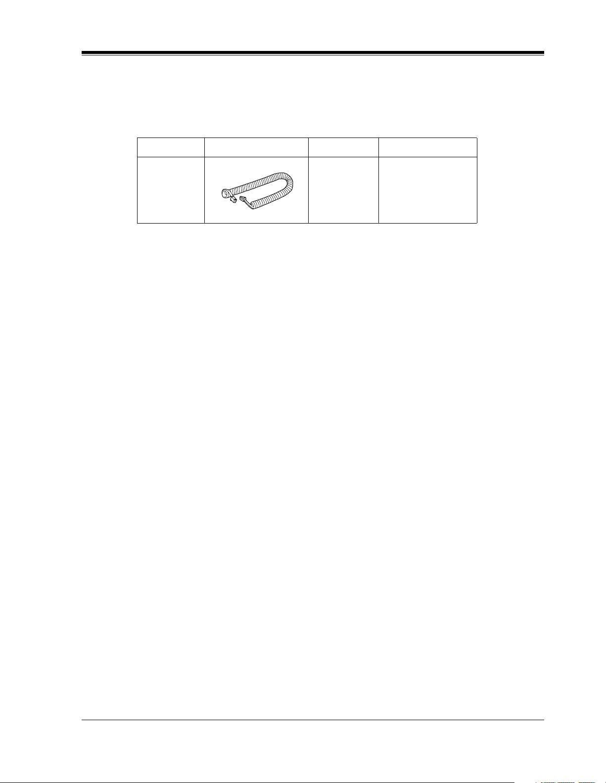
Part No. Picture Description Comment
Attention
KX-J07W/B
KX-J15W/B
KX-J25W/B
W:White B:Black
When you ship the product
Carefully pack and send it prepaid, adequately insured and preferably in the original carton.
Attach a postage-paid letter, detailing the symptom, to the outside of the carton. DO NOT send
the product to the Executive or Regional Sales offices. They are NOT equipped to make repairs.
Product service
Panasonic Factory Servicenters for this product are listed in the servicenter directory. Consult
your authorized Panasonic dealer for detailed instructions.
Handset cord
213.36 cm (7 feet)
457.2 cm (15 feet)
762 cm (25 feet)
Installation Manual 7

Attention
The serial number of this product may be found on the label affixed to the bottom
of the unit. You should note the model number and the serial number of this unit in
the space provided and retain this book as a permanent record of your purchase to aid
in identification in the event of theft.
MODEL NO.:
SERIAL NO.:
For your future reference
DATE OF PURCHASE
NAME OF DEALER
DEALER’S ADDRESS
DEALER’S TEL NO.
8 Installation Manual

Telephone Company and F.C.C. Requirements and Responsibilities
Telephone Company and F.C.C. Requirements
and Responsibilities
1.
Notification to the Telephone Company
Customers, before connecting terminal equipment to the telephone network, shall upon
request of the Telephone Company, inform the Telephone Company of the particular line(s)
to which such connection is made, the F.C.C. registration number (see the label on the
bottom of the unit) and ringer equivalence number (REN) of the registered terminal
equipment.
The REN is useful to determine the quantity of devices you may connect to your telephone
line and still have all of those devices ring when your telephone number is called. In most,
but not all areas, the sum of the REN's of all devices connected to one line should not exceed
five (5.0). To be certain of the number of devices you may connect to your line, as
determined by the REN, you should contact your local telephone company to determine the
maximum REN for your calling area.
2.
Connection to Telephone Line
This unit must not be connected to a coin operated line. If you are on a party line, check
with your local telephone company.
3.
Incidence of Harm to the Telephone Lines
Should terminal equipment cause harm to the telephone network, the telephone company
shall, where practical, notify the customer that temporary discontinuance of service may be
required.
However, where prior notice is not practical, the telephone company may temporarily
discontinue service forthwith, if such action is reasonable in the circumstances. In case of
such unnotified temporary discontinuance of service, the telephone company shall:
1) Promptly notify the customer of such temporary discontinuance of service.
2) Afford the customer the opportunity to correct the situation which gave rise to the
temporary discontinuance.
3) Inform the customer of the right to bring a complaint to the Federal Communication
Commission pursuant to the procedures set out in Subpart E of Part 68 of FCC
Telephone Equipment Rules.
4.
Compatibility of the Telephone Network and Terminal Equipment
a)
Availability of telephone interface information.
Technical information concerning interface parameters and specifications not specified
in FCC Rules, including the number of Ringers which may be connected to a particular
telephone line, which is needed to permit Terminal Equipment to operate in a manner
compatible with Telephone Company communications facilities, shall be provided by
the Telephone Company upon customer's request.
b)
Changes in Telephone Company Communications Facilities, Equipment,
Operations and Procedures.
The Telephone Company may make changes in its communications facilities,
equipment, operations or procedures, where such action is reasonably required in the
operation of its business and is not inconsistent with the rules and regulations in FCC
Part 68.
Installation Manual 9

Telephone Company and F.C.C. Requirements and Responsibilities
If such changes can be reasonably expected to render any customer Terminal Equipment
incompatible with Telephone Company Communications Facilities, or require
modification or alteration of such Terminal Equipment, or otherwise materially affect its
use or performance, the customer shall be given adequate notice in writing, to allow the
customer an opportunity to maintain uninterrupted service.
Notify the Telephone Company
Installation must be performed by a qualified professional installer. If required, provide the
telephone company with the following technical information:
• Telephone numbers to which the system will be connected
• Make: Panasonic
• Model: KX-TA1232
• FCC Registration No.: found on the bottom of the unit
• Ringer Equivalence No.: 0.4B
• Facility Interface Code: 02LS2
• Service Order Code: 9.0F, AS.2
• Required Network Interface Jack: RJ11 / 14C
Note
This equipment has been tested and found to comply with the limits for a Class A digital
device, pursuant to Part 15 of the FCC Rules. These limits are designed to provide reasonable
protection against harmful interference when the equipment is operated in a commercial
environment. This equipment generates, uses, and can radiate radio frequency energy and, if
not installed and used in accordance with the instruction manual, may cause harmful
interference to radio communications. Operation of this equipment in a residential area is likely
to cause harmful interference in which case the user will be required to correct the interference
at his own expense.
CAUTION
Any changes or modifications not expressly approved by the party responsible for compliance
could void the user's authority to operate this device.
When programming emergency numbers and / or making test calls to emergency numbers:
1. Remain on the line and briefly explain to the dispatcher the reason for the call before
hanging up.
2. Perform such activities in the off-peak hours, such as early morning hours or late evenings.
10 Installation Manual

Introduction
This Installation Manual provides technical information for the Panasonic Advanced Hybrid
System, KX-TA1232. It is designed to serve as an overall technical reference for the system
and includes a description of the system, its hardware and software, features and services and
environmental requirements.
This manual contains the following sections:
Section 1, System Outline
Provides general information on the system including system capacity and specifications.
Section 2, General Installation
Contains the basic system installation and wiring instructions, as well as how to install the
optional cards and units.
Section 3, Troubleshooting
Provides information for system and telephone troubleshooting.
Section 4, Index
Provides the important words and phrases to help you access the required information easily.
Terms used in this Installation Manual
Telephone Company and F.C.C. Requirements and Responsibilities
Programming Guide References
The related and required programming titles described in the Programming Guide
your reference.
Programming Guide reference is also shown in the sentences as follows.
Example: <SYS PRG [109]>
Explanation: Refer to system program [109] in the Programming Guide.
This helps you know the related and required programming easily for the contents of the
sentences.
Features Guide References
The related feature titles described in the Features Guide
About the other manuals
Along with this Installation Manual, the following manuals are available to help you know the
available features, program and use the KX-TA1232 system.
Features Guide
Provides information about the system features.
Programming Guide
Provides system programming instructions.
are noted for
are noted for your reference.
User Manual
Provides operating instructions for the end users using proprietary telephones, single line
telephones, consoles.
Installation Manual 11

Table of Contents
Table of Contents
1 System Outline
1.1 System Highlights ........................................................................................................ 16
1.1.1 System Highlights ...................................................................................................... 16
1.2 Basic System Construction ......................................................................................... 18
1.2.1 Basic System Construction......................................................................................... 18
1.2.2 System Connection Diagram...................................................................................... 19
1.3 Proprietary Telephones............................................................................................... 21
1.3.1 Proprietary Telephones............................................................................................... 21
1.4 Options.......................................................................................................................... 22
1.4.1 Options ....................................................................................................................... 22
1.5 Specifications................................................................................................................ 23
1.5.1 General Description.................................................................................................... 23
1.5.2 Characteristics ............................................................................................................24
1.5.3 System Capacity ......................................................................................................... 25
2 General Installation
2.1 Before Installation ....................................................................................................... 28
2.1.1 Before Installation ...................................................................................................... 28
2.2 Installation of the Main Unit ...................................................................................... 30
2.2.1 Unpacking................................................................................................................... 30
2.2.2 Location of Interfaces................................................................................................. 31
2.2.3 Wall Mounting............................................................................................................ 32
2.2.4 Opening Front Cover.................................................................................................. 34
2.2.5 Frame Ground Connection ......................................................................................... 35
2.3 Connection.................................................................................................................... 37
2.3.1 Outside Line Connection............................................................................................ 37
2.3.2 Extension Connection................................................................................................. 38
2.3.3 Telephone Connection................................................................................................ 43
2.3.4 Polarity Sensitive Telephone Connection .................................................................. 45
2.3.5 External Pager (Paging Equipment) Connection........................................................ 47
2.3.6 External Music Source Connection............................................................................ 48
2.3.7 Printer and PC Connection ......................................................................................... 50
2.3.8 Installation of Lightning Protectors............................................................................ 54
2.4 Installation of Optional Cards and Units .................................................................. 57
2.4.1 Location of Optional Cards and Units........................................................................ 57
2.4.2 4 CO Line Expansion Unit Connection...................................................................... 60
2.4.3 8 Extension Expansion Unit Connection.................................................................... 61
2.4.4 Installing Expansion Unit........................................................................................... 62
2.4.5 DISA Card Installation............................................................................................... 70
2.4.6 Caller ID Card Installation ......................................................................................... 71
2.4.7 Doorphone and Door Opener Connection .................................................................. 73
2.4.8 Doorbell/Door Chime Connection ............................................................................. 79
2.5 Auxiliary Connection for Power Failure Transfer................................................... 81
2.5.1 Auxiliary Connection for Power Failure Transfer...................................................... 81
2.6 Closing the Front Cover.............................................................................................. 82
2.6.1 Closing the Front Cover ............................................................................................. 82
12 Installation Manual

Table of Contents
2.7 Starting the System for the First Time.......................................................................84
2.7.1 Starting the System for the First Time ........................................................................84
2.8 System Restart ..............................................................................................................86
2.8.1 System Restart.............................................................................................................86
2.9 System Data Clear........................................................................................................87
2.9.1 System Data Clear .......................................................................................................87
3 Troubleshooting
3.1 Troubleshooting............................................................................................................90
3.1.1 Installation...................................................................................................................90
3.1.2 Connection ..................................................................................................................91
3.1.3 Operation.....................................................................................................................93
3.1.4 Using the Reset Button................................................................................................94
4 Index .................................................................................................97
Installation Manual 13

Table of Contents
14 Installation Manual

System Outline
Section 1
System Outline
This section provides general information on the
system, including system capacity and specifications.
Installation Manual 15

System Outline
1.1 System Highlights
1.1.1 System Highlights
System Maximum Capacity
KX-
Extension PT&SLT 32
TA1232
Outside
Line
Analog 12
Module Expansion
Expansion modules are used to increase the system capacity.
Paralleled Telephone Connection
Every jack in the system also supports the parallel connection of a proprietary telephone and a
single line device. They share the same extension number and are considered by the system to
be one extension.
Advanced Hybrid System
This system supports the connection of analog proprietary telephones, a DSS Console and
single line devices such as single line telephones, fax machines, and data terminals.
Analog Proprietary Telephones (APT)
The system supports six different models of analog proprietary telephones.
Programming System
The system can be programmed from a proprietary telephone.
Voice Mail Integration
The system supports Voice Processing Systems with in-band DTMF signaling as well as DPT
integration. The Panasonic Voice Processing System provides automated attendant, voice mail,
interview and custom services.
16 Installation Manual

Caller ID
Allows the user to see the name or telephone number of a caller on the telephone display before
answering a call.
Trunk (Outside Line) Answer From Any Station (TAFAS)
Ringing occurs over the external paging system; the call can be answered from any station.
Remote Station Lock Control
Allows an operator to lock an extension so that outgoing calls cannot be made.
System Outline
Installation Manual 17
System Outline
A1232
Panasonic
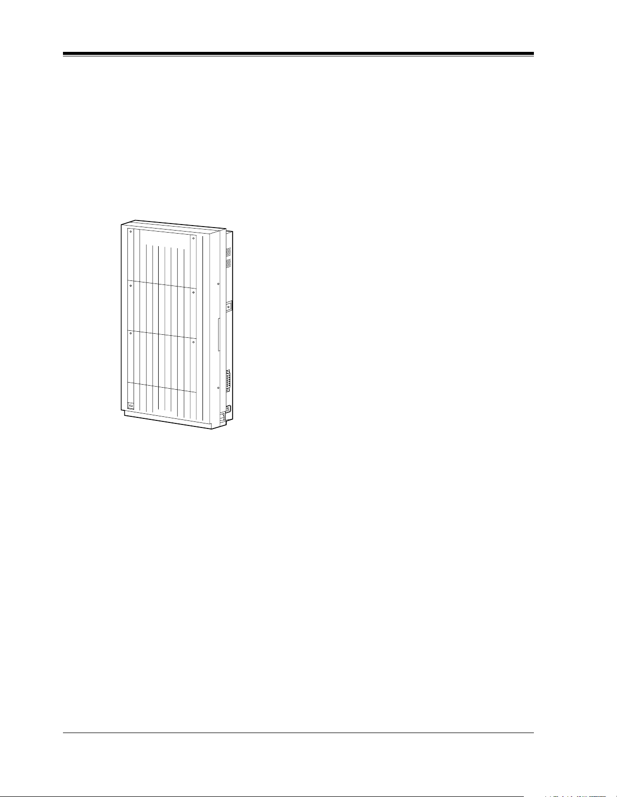
1.2 Basic System Construction
1.2.1 Basic System Construction
The KX-TA1232 Advanced Hybrid System has a basic capacity of eight outside lines and 16
extensions. It is capable of supporting Panasonic analog proprietary telephones, a DSS Console
and single line devices such as single line telephones and fax machines.
To expand its capabilities, the system can be equipped with optional components or customersupplied peripherals such as external speakers and external music sources (e.g., radios).
A1232
A
D
V
A
N
C
E
D
H
Y
B
R
ID
S
Y
S
T
E
M
K
X
-
T
A
1
2
3
2
P
a
n
a
s
o
n
ic
18 Installation Manual
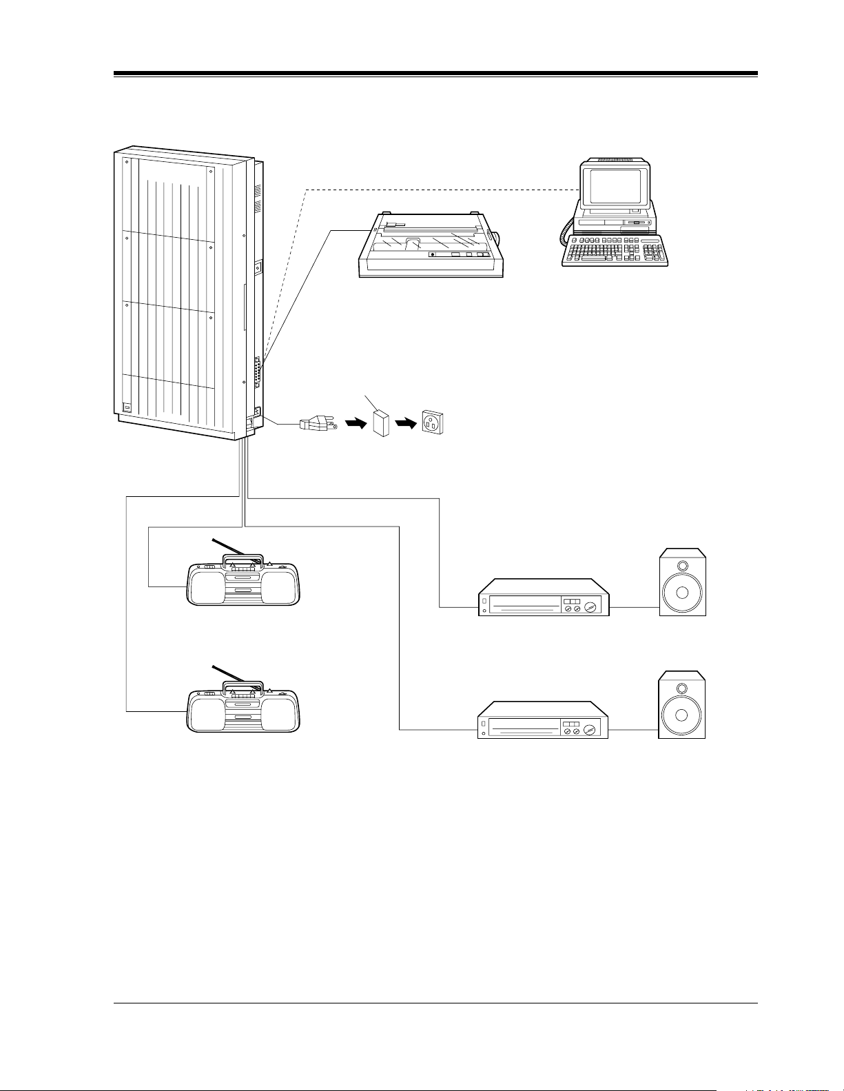
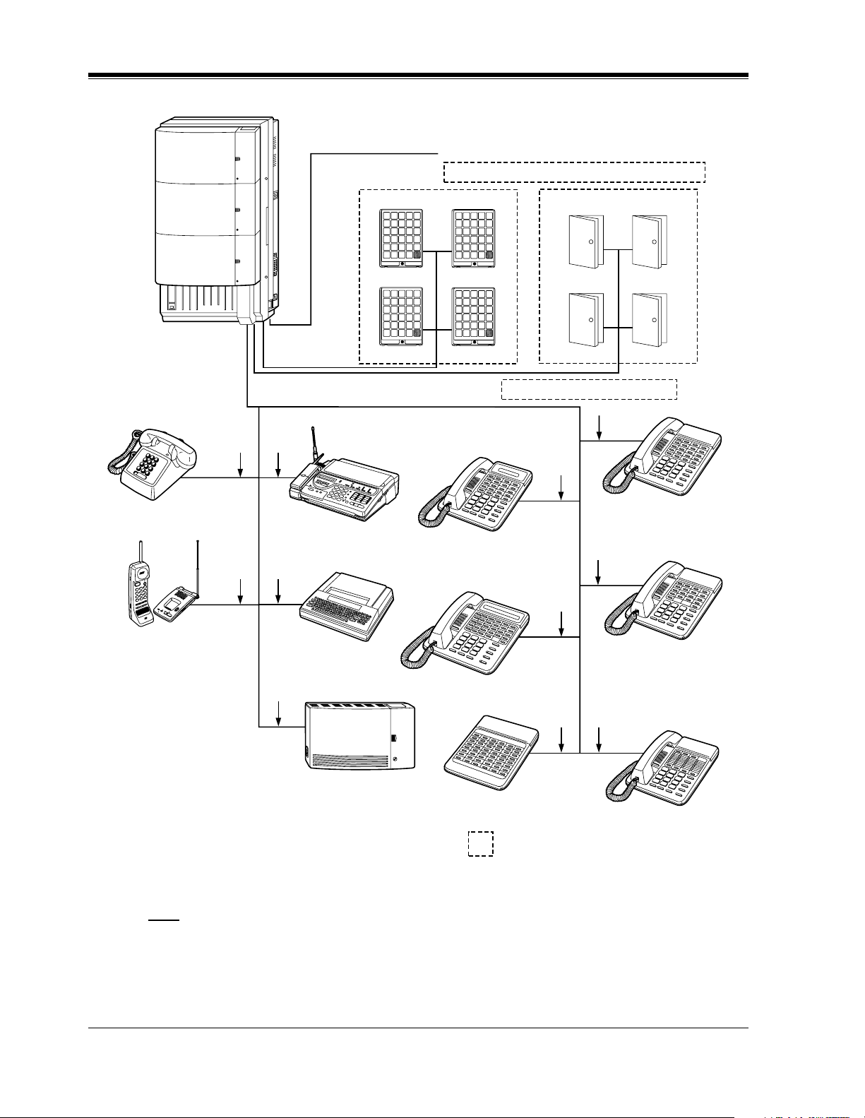
1.2.2 System Connection Diagram
Panasonic
A1232
ADVANCED HYBRID SYSTEM KX-TA1232
Printer or PC for SMDR (Station Message Detail Recording)
AC Surge Protector
System Outline
Panasonic
External Music Source 1
External Music Source 2
120 V AC, 60 Hz
Amplifier Speaker 1
Amplifier Speaker 2
Avoid using the same AC
outlet for office equipment
and the KX-TA1232. Use a
dedicated AC outlet only.
Installation Manual 19
System Outline
Panasonic
Panasonic
Panasonic
Panasonic
Panasonic
Panasonic
Panasonic
D1232
S
L
A
T
I
G
E
D
Single Line Telephone
Panasonic
ic
n
o
s
a
n
a
P
M
E
T
S
Y
S
D
I
R
B
Y
H
R
E
P
U
(Lightning Protectors)
to outside lines 1 through 8 (initial)
12 Outside Lines
Doorphone KX-T30865
P
a
na
Doorphone 1
P
a
n
a
s
o
n
ic
P
ana
Doorphone 3 Doorphone 4
to outside lines 9 through 12 (additional)
so
n
ic
so
nic
P
an
as
on
ic
Doorphone 2
P
a
nas
on
ic
Door Opener 1 Door Opener 2
Door Opener 3 Door Opener 4
32 Extensions (16 extensions – initial, 16 extensions – additional)
(two pair)
(one
(one
pair)
pair)
(one
pair)
Telephone Answering
Machine with Facsimile
(one pair)
KX-T7030
(two
pair)
KX-T7020
(two pair)
(two
pair)
Cordless Phone
(one
pair)
Data Terminal
KX-T7130 / KX-T7135
KX-T7050
(one
(two pair)
pair)
Voice Processing System
KX-T7040
KX-T7055
: needs Optional Cards or Adaptor.
Note
• It is recommended that extension of jack 1 is a display proprietary telephone.
• Parallel connection of telephones is possible. Refer to the Paralleled Telephone Connection
in 2.3.3 Telephone Connection.
20 Installation Manual

1.3 Proprietary Telephones
1.3.1 Proprietary Telephones
The following Panasonic proprietary telephones are available with this system.
System Outline
Proprietary
Telephone
KX-T7135 1-line backlit display, speakerphone, 12 Flexible
CO, 12 PF
KX-T7130 1-line display, speakerphone, 12 Flexible CO,
12 PF
KX-T7020 Speakerphone, 12 Flexible CO, 4 PF
KX-T7030 1-line display, speakerphone, 12 Flexible CO,
4 PF
KX-T7050 Monitor, 12 Flexible CO, 4 PF
KX-T7055 Monitor, 3 Flexible CO, 3 PF
Note
Flexible CO : Flexible CO button (programmable)
PF : Programmable Feature button
Description
Installation Manual 21

System Outline
1.4 Options
1.4.1 Options
Max.
Model No. Model Name Description
KX-TA123270 8 Extension Expansion Unit Adds 8 extension lines. 2
KX-TA123280 4 CO Line Expansion Unit Adds 4 outside lines. 1
Quantity on
KX-TA1232
KX-TA123291 DISA Card Supports the Direct Inward System
Access (DISA) feature and records
outgoing messages.
KX-TA123293 Caller ID Card Supports the Caller ID Service of
the central office.
KX-TA123260 Doorphone / Door Opener
Interface Card
KX-T7040 DSS Console Provides easy and quick access to
KX-T30865 Doorphone Used for a doorphone call. 4
Supports 4 doorphones and 4 door
openers.
extensions and features. This must
be used with a proprietary
telephone.
1
3
1
4
22 Installation Manual
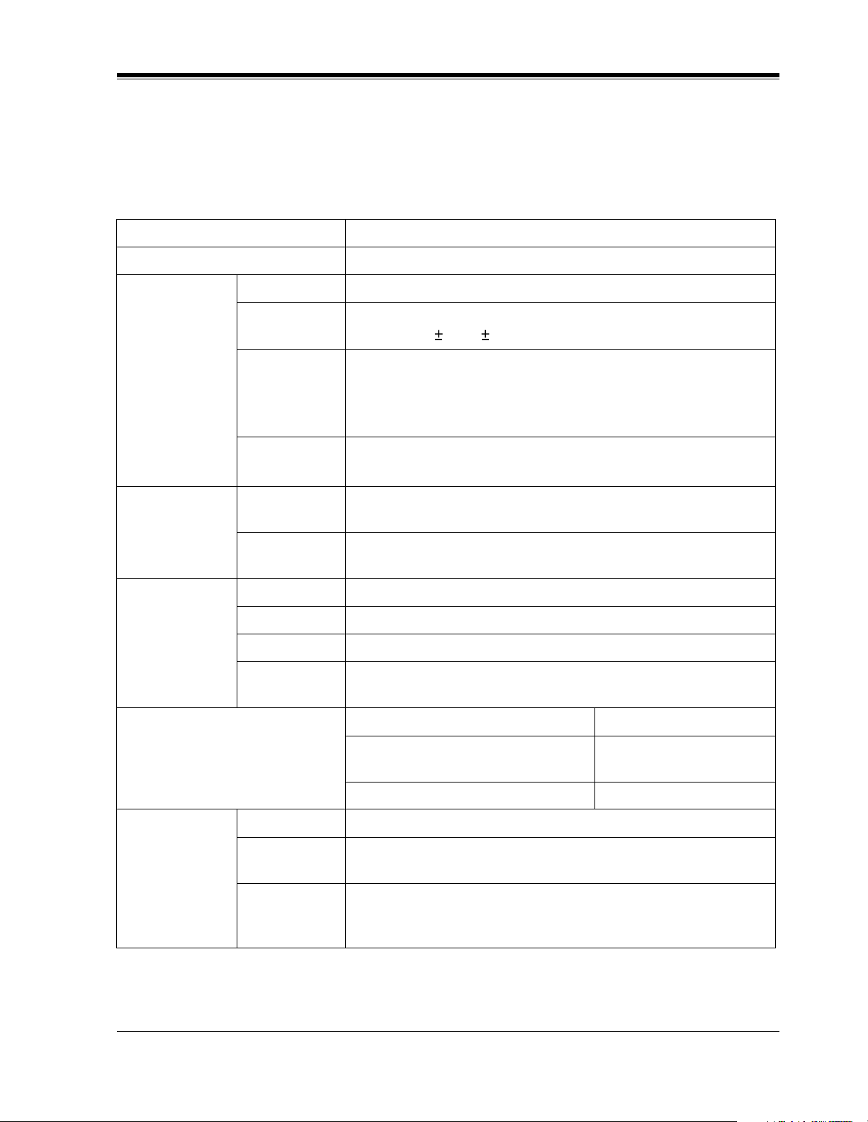
1.5 Specifications
1.5.1 General Description
Control Method CPU: 16-bit CPU
Switching Non Blocking PCM Time Switch
Power Supplies Primary 120 V AC, 60 Hz
Secondary Station Supply Volt: 30 V
Circuit Volt: 5 V, 15 V
Power Failure • Memory backup duration: seven years with the factory-provided
lithium battery
• 3 outside lines max. for KX-TA1232 automatic transfer to
extensions (Power Failure Transfer)
System Outline
Power
Consumption
Dialing Outward Dial Pulse (DP) 10 pps, 20 pps
Internal Dial Pulse (DP) 10 pps, 20 pps
Connectors Outside lines Modular Jack (RJ14C)
Extensions Amphenol Connector
Paging Output Pin Jack (RCA JACK)
External
Music Input
Extension Connection Cable Single line telephones 1 pair wire (T, R)
Station
Message Detail
Recording
(SMDR)
Interface Serial Interface (RS-232C) (D-SUB, 25-pin)
Output
Equipment
Detail
Recording
87 W (under maximum load conditions)
0 W (when power switch is off)
Tone (DTMF) Dialing
Tone (DTMF) Dialing
Two-conductor Jack (MINIJACK 3.5 mm diameter)
KX-T7135, KX-T7130, KX-T7020,
KX-T7030, KX-T7050, KX-T7055
KX-T7040 1 pair wire (L, H)
Printer
Date, Time, Extension Number, Outside Line Number, Dialed
Number, Ring Duration, Call Duration, Account Code, Caller ID,
Timed Reminder
2 pair wire (T, R, L, H)
Installation Manual 23
System Outline
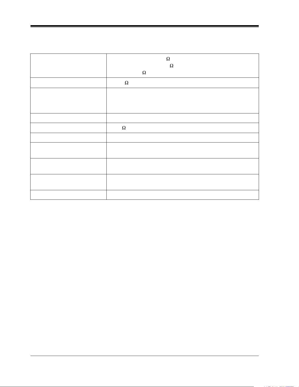
1.5.2 Characteristics
Station Loop Limit
Minimum Leakage Resistance
Maximum Number of Station
Instruments per Line
Ring Voltage 70 Vrms at 20 Hz depending on the Ringing Load
Central Office Loop Limit
Environmental Requirements 0 °C – 40 °C (32 °F – 104 °F), 10 % – 90 % relative humidity
Hookswitch Flash Timing
Range
Door Opener /
Doorbell/Door Chime
Dimensions (W x H x D) 325 mm x 640 mm x 115 mm
Mass (Weight) 7.8 kg (17.2 lb)
Proprietary Telephone: 40
Single Line Telephone: 600 including set
Doorphone: 20
15 000
1 for proprietary telephone or single line telephone
2 by Parallel Connection of a proprietary telephone and a single line
telephone
1 600 max.
200 ms – 1000 ms
30 V DC, 5 A (Max.)/250 V AC, 5 A (Max.)
(12-13/16 x 25-3/16 x 4-1/2 inches)
24 Installation Manual

1.5.3 System Capacity
Lines, Station Equipment
Actual capacity will depend on the number or / and type of units connected to the system.
Item Max.
Quantity
TA1232
Doorphones 4
Door Openers 4
Doorbell/Door Chime 4
External Pagers 2
External Music Sources 2
System Outline
on
KX-
System Data
Item Max. Quantity
Operators 2
System Speed Dialing 500
One-Touch Dialing 24 per extension
(proprietary telephone)
Personal Speed Dialing 10 per extension
Call Park areas 10
Absent Messages 9
Outside Line Groups 8
Toll Restriction Levels 8
Extension Groups 8
Class of Service levels 8
Message Waitings 128
Installation Manual 25

System Outline
26 Installation Manual

General Installation
Section 2
General Installation
Installation Manual 27

General Installation
2.1 Before Installation
2.1.1 Before Installation
Please read the following notes concerning installation and connection before installing the
system and terminal equipment.
Safety Installation Instructions
When installing telephone wiring, basic safety precautions should always be followed to
reduce the risk of fire, electric shock and injury to persons, including the following:
a) Never install telephone wiring during a lightning storm.
b) Never install telephone jacks in wet locations unless the jack is specifically designed for
wet locations.
c) Never touch uninsulated telephone wires or terminals unless the telephone line has been
disconnected at the network interface.
d) Use caution when installing or modifying telephone lines.
Installation Precautions
This system is designed for wall mounting only. Avoid installing in the following places.
(Doing so may result in malfunction, noise, or discoloration.)
a) In direct sunlight and hot, cold, or humid places. (Temperature range: 0 °C – 40 °C / 32
°F – 104 °F)
b) Sulfuric gases produced in areas where there are thermal springs, etc. may damage the
equipment or contacts.
c) Places in which shocks or vibrations are frequent or strong.
d) Dusty places, or places where water or oil may come into contact with the system.
e) Near high-frequency generating devices such as sewing machines or electric welders.
f) On or near computers, telexes, or other office equipment, as well as microwave ovens or
air conditioners. (It is preferable not to install the system in the same room with the
above equipment.)
g) Install at least 1.8 m (6 feet) away from radios and televisions. (Both the system and
Panasonic proprietary telephones)
h) Do not obstruct area around the system (for reasons of maintenance and inspection —
be especially careful to allow space for cooling above and at the sides of the system).
Wiring Precautions
Be sure to follow these instructions when wiring the unit:
a) To assure good quality telephone connection, it is recommended new and modifications
to existing installation of customer premise wiring shall use solid twisted pair copper
28 Installation Manual
General Installation
conductors with minimum 24 gauge that comply with the electrical specifications for
Category 3 wiring as detailed in ANSI/EIA/TIA-570A Building Wiring Standards.
b) Do not wire the telephone cable in parallel with an AC power source, computer, telex,
etc. If the cables are run near those wires, shield the cables with metal tubing or use
shielded cables and ground the shields.
c) If cables are run on the floor, use protectors to prevent the wires from being stepped on.
Avoid wiring under carpets.
d) Avoid using the same power supply outlet for computers, telexes, and other office
equipment. Otherwise, the system operation may be interrupted by the induction noise
from such equipment.
e) Please use one pair telephone wire for extension connection of (telephone) equipment
such as single line telephones, data terminals, answering machines, computers, voice
processing systems, etc., except Panasonic proprietary telephones (e.g., KX-T7135,
KX-T7130).
f) The Power Switch of the system must be off during wiring. After all of the wiring is
completed, turn the Power Switch on.
g) Mis-wiring may cause the system to operate improperly. Refer to 3.1.1 Installation
and 3.1.2 Connection.
h) If an extension does not operate properly, disconnect the telephone from the extension
line and then connect again, or turn off the Power Switch of the system and then on
again.
i) The system is equipped with a 3-wire grounding type plug. This is a safety feature. If
you are unable to insert the plug into the outlet, contact your electrician to replace your
obsolete outlet. Do not defeat the purpose of the grounding-type plug.
j) Use twisted pair cable for outside line connection.
k) Outside lines should be installed with lightning protectors. For details, refer to
2.3.8 Installation of Lightning Protectors.
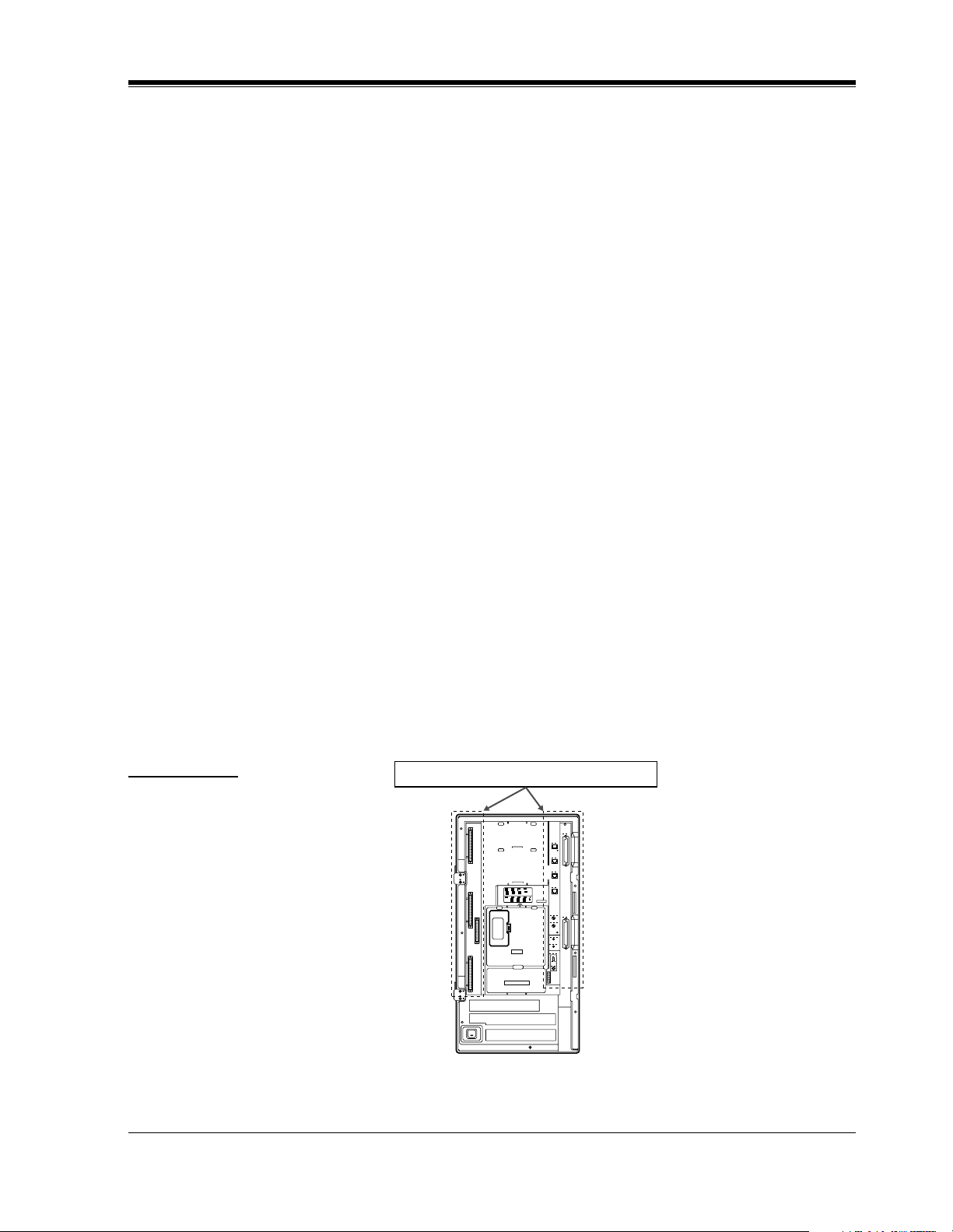
WARNING
Warning: Static sensitive connectors
Static sensitive devices are used. To
protect printed circuit boards from
static electricity, do not touch
connectors indicated to the right.
To discharge body static, touch
ground or wear a grounding strap.
DISA
DOORPHONE
Installation Manual 29

General Installation
2.2 Installation of the Main Unit
2.2.1 Unpacking
Unpack the box and check the items below:
KX-TA1232
Main Unit one
AC Cord one
Template one
Screws (Wall Mounting) four
Pager Connectors two
Music Source Connectors two
Expansion Line Cord Holder one
30 Installation Manual
 Loading...