

Page 1
Quick Installation Guide
2.4 GHz Cell Station Unit
Model No.
KX-TDA0142
KX-TDA0152
KX-T0141
KX-T0151
Thank you for purchasing a Panasonic 2.4 GHz Cell Station Unit.
Please read this manual carefully before using this product and save this manual for future use.
Document Version: 2009-12
Page 2
SAVE THESE INSTRUCTIONS
Important Information
Important Information
Safety Notices
Please observe the safety notices in this manual in order to avoid danger to users or other people, and prevent
damage to property.
The notices are classified as follows, according to the severity of injury or damage:
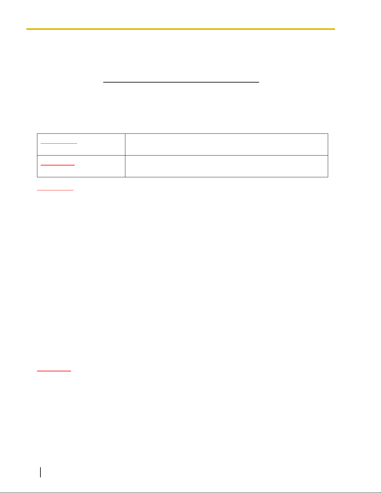
WARNING
CAUTION
This notice means that misuse could result in death or serious injury.
This notice means that misuse could result in injury or damage to
property.
WARNING
SAFETY REQUIREMENTS
• The product must only be installed and serviced by qualified service personnel. The product should be
used as-is from the time of purchase; it should not be disassembled or modified. Disassembly or
modification can cause a fire, electric shock, or damage to the product.
• Make sure that the wall that the unit will be attached to is strong enough to support the unit (approx.
310 g [11 oz]). If not, it is necessary for the wall to be reinforced.
• Only use the wall-mounting equipment (screws, washers, wall mounting plate) included with the unit.
• When this product is no longer in use, make sure to detach it from the wall.
• Do not connect or disconnect the telephone cord with wet hands.
• Disconnect the unit from the telephone cord, and contact the dealer if:
– The unit is exposed to rain, water, or any other liquid.
– The unit is dropped or damaged.
– Internal components are exposed due to damage.
– The unit does not operate properly.
– Performance deteriorates.
• Disconnect the unit from the telephone cord if the unit emits smoke, an abnormal smell, or makes
unusual noise. These conditions can cause fire or electric shock. Confirm that smoke has stopped and
contact an authorized service center.
• Do not touch the unit, or telephone cord during a lightning storm.
• Do not allow anything to rest on the telephone cord. Do not locate this unit where the telephone cord
may be stepped on or tripped on.
CAUTION
SAFETY REQUIREMENTS
• The CS should be kept free of dust, moisture, high temperature (more than 40 °C [104 °F]), low
temperature (less than 0 °C [32 °F]), and vibration, and should not be exposed to direct sunlight.
• The CS should not be placed outdoors (use indoors).
• The CS should not be placed near high-voltage equipment.
• The CS should not be placed on a metal object.
• Systems using 2.4 GHz ISM (Industrial, Scientific and Medical) band may interfere with the Panasonic
wireless system. Examples of such systems are cordless telephones, wireless LAN, Home RF,
microwave ovens and other ISM devices. These systems may cause minor noise.
2 Quick Installation Guide Document Version 2009-12
Page 3

Important Information
• When driving the screws into the wall, be careful to avoid touching any metal laths, wire laths or metal
plates in the wall.
• To prevent malfunction, deformity, overheating, rust, and discoloration, do not install or place
equipment in the following types of locations:
– Locations where air ventilation is poor.
– Locations that may be exposed to sulphurous gas, such as near hot springs.
– Near devices that emit heat, such as heaters.
– Near devices that emit electromagnetic noise, such as radios or televisions.
– Near devices that emit high-frequency noise, such as sewing machines or welders.
• Do not stretch or bend the cables. Also, do not allow anything to rest on the cables.
• Use cables that are fire-resistant or fireproof.
• The CS and the cables should never be placed near or over a radiator or other heat source.
• Do not bundle cables that are connected to the CS with the AC power cords of machines located
nearby.
• Make sure the cables are securely fastened to the wall.
• Disconnect the telephone cord from the unit before cleaning. Clean the unit with a soft, dry cloth. Do
not use liquid, aerosol cleaners, abrasive powders, or chemical agents to clean the unit.
• When left unused for a long period of time, disconnect the unit from the telephone cord.
• Medical—consult the manufacturer of any personal medical devices, such as pacemakers, to
determine if they are adequately shielded from external RF (radio frequency) energy. (The unit operates
in the frequency range of 2400 MHz to 2483 MHz, and the output peak power level is less than
0.25 W.) Do not use the unit in health care facilities if any regulations posted in the area instruct you
not to do so. Hospitals or health care facilities may be using equipment that could be sensitive to
external RF (radio frequency) energy.
Notice
SAFETY REQUIREMENTS
• Before connecting the unit, confirm that the unit supports the intended operating environment.
• If the unit does not operate properly, disconnect the telephone cord, then connect again.
• The unit may not operate in the event of a power failure.
• Do not move the unit while it is in use.
• Satisfactory operation, interoperability, and compatibility cannot be guaranteed with all equipment
connected to the unit, nor with all services provided by telecommunications providers over networks
connected to the unit.
SECURITY REQUIREMENTS
• Privacy of communications may not be ensured when using the wireless systems.
Document Version 2009-12 Quick Installation Guide 3
Page 4

Important Information
Additional Information
F.C.C. REQUIREMENTS AND RELEVANT INFORMATION
CAUTION
Any changes or modifications not expressly approved by the party responsible for compliance could void
the user's authority to operate this device.
Note
This equipment has been tested and found to comply with the limits for a Class B digital device, pursuant
to Part 15 of the FCC Rules. These limits are designed to provide reasonable protection against harmful
interference in a residential installation. This equipment generates, uses, and can radiate radio frequency
energy and, if not installed and used in accordance with the instructions, may cause harmful interference
to radio communications. However, there is no guarantee that interference will not occur in a particular
installation. If this equipment does cause harmful interference to radio or television reception, which can
be determined by turning the equipment off and on, the user is encouraged to try to correct the interference
by one or more of the following measures:
• Reorient or relocate the receiving antenna.
• Increase the distance between the equipment and receiver.
• Connect the equipment to an outlet on a circuit different from that to which the receiver is connected.
• Consult the dealer or an experienced radio/TV technician for help.
Some wireless telephones operate at frequencies that may cause interference to nearby TVs and VCRs.
To minimize or prevent such interference, the base of the wireless telephone should not be placed near
or on top of a TV or VCR. If interference is experienced, move the wireless telephone further away from
the TV or VCR. This will often reduce, or eliminate, interference.
RF Exposure Warning:
This product complies with FCC radiation exposure limits set forth for an uncontrolled environment. To comply
with FCC RF exposure requirements, this product must be installed and operated in accordance with the
provided instructions. The installed unit requires a minimum 20 cm (8 inches) of spacing between the antenna
and a person's body (excluding hands, wrists and feet) during wireless modes of operation.
This transmitter must not be co-located or operated in conjunction with any other antennas or transmitters.
4 Quick Installation Guide Document Version 2009-12
Page 5

Table of Contents
Table of Contents
1 Overview ...................................................................................................6
2 Procedure Overview ................................................................................9
3 Site Planning ..........................................................................................11
4 Before Site Survey .................................................................................15
5 Site Survey ..............................................................................................19
6 After Site Survey ....................................................................................23
7 Connecting a Cell Station to the PBX ..................................................24
8 Wall Mounting .........................................................................................34
9 Troubleshooting .....................................................................................39
Document Version 2009-12 Quick Installation Guide 5
Page 6
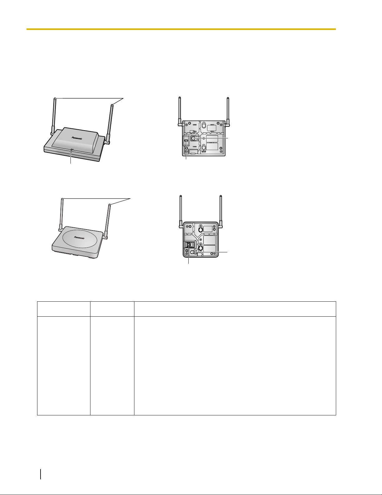
LED
Antennas
DIP Switch
RJ11 Modular
Antennas
RJ11 Modular
DIP Switch
1 Overview
1 Overview
Names and Locations
KX-T0151/KX-TDA0152
KX-T0141/KX-TDA0142
LED Indications (KX-T0151/KX-TDA0152)
Indication
STATUS Green/Red CS status indication
6 Quick Installation Guide Document Version 2009-12
Color Description
• OFF: Power Off
• Green ON: Stand-by (no active calls)
• Slow Green Flashing (60 times per minute): Talk (active calls)
• Moderate Green Flashing (120 times per minute): Busy
• Red ON: Fault (includes Initialization)
• Red Flashing (60 times per minute): Out of Service/Starting up
CS status indication during the site survey
• Red ON: The CS is connected to an AC adaptor/battery box.
• Red Flashing (60 times per minute): The CS is connected to the
PBX.
Page 7
1 Overview
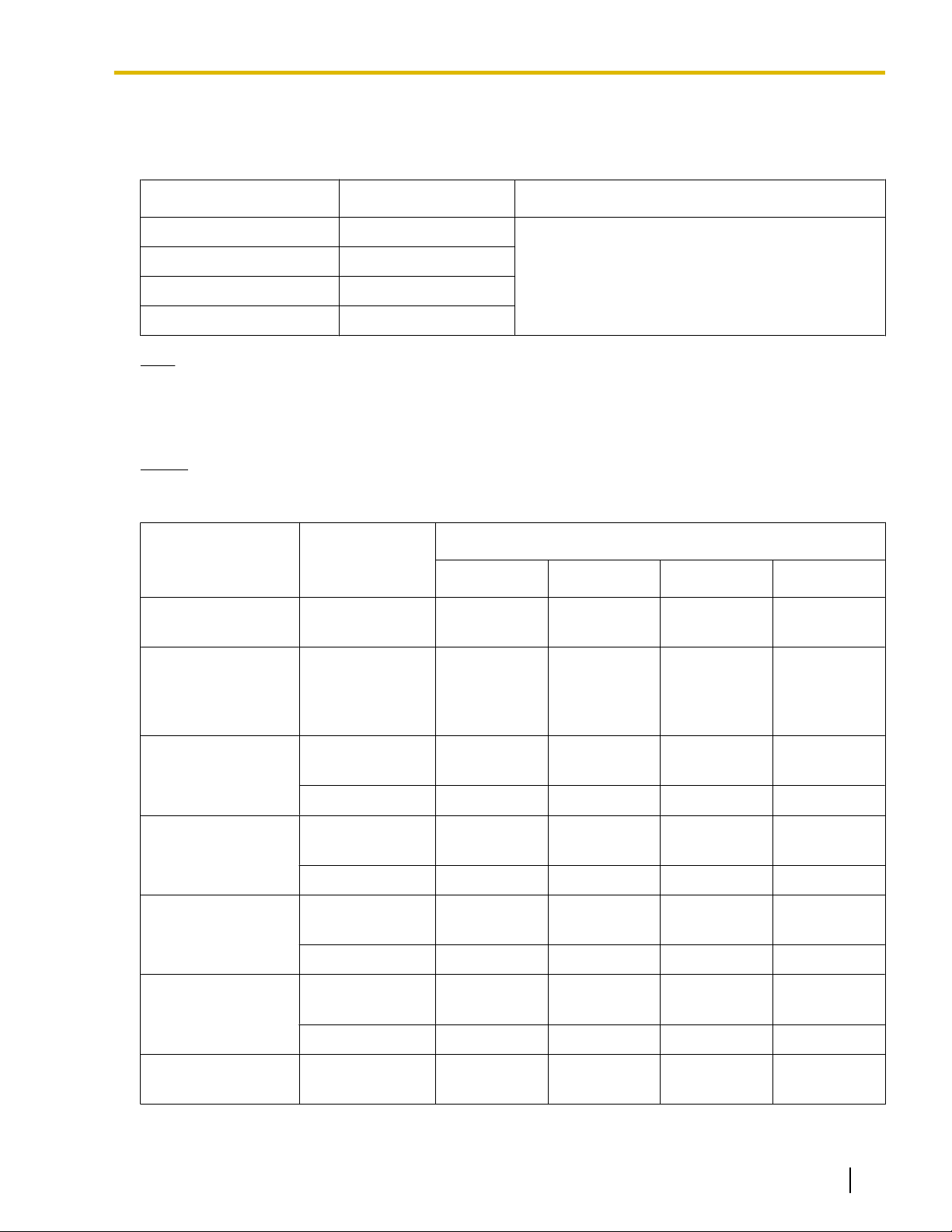
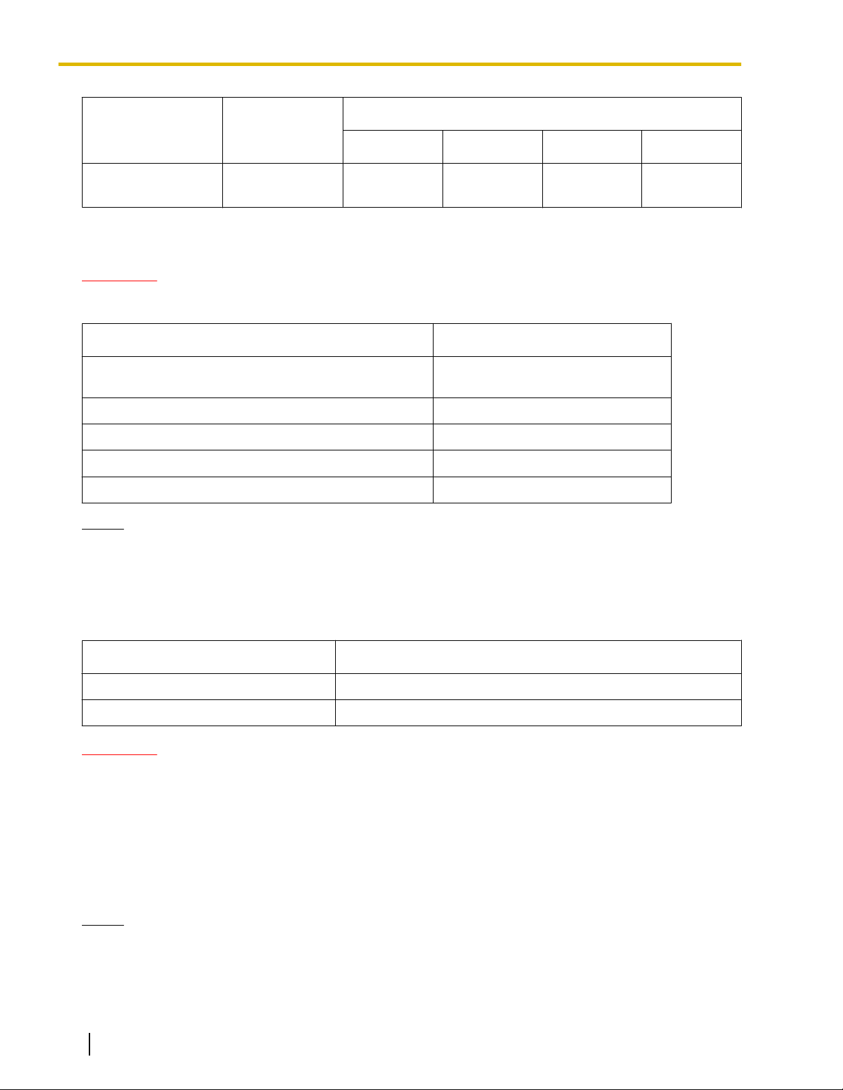
Maximum Number of Calls
Cell Stations (CSs) determine the area covered by the wireless system. The number of calls that can be made
simultaneously through each CS varies depending on the model, as follows:
Cell Station Maximum Calls Compatible Portable Station
KX-T0151 2
KX-TDA0152 3
KX-T0141 2
KX-TDA0142 3
Note
For more details about the Portable Station (PS), refer to the Operating Instructions of the PS.
• KX-TD7684
• KX-TD7694
• KX-TD7680
• KX-TD7690
Maximum Number of CSs Supported by PBX
Notice
The CSs are for connection to specified Panasonic PBXs only.
The following number of CSs can be supported by each PBX.
PBX
KX-TAW848
KX-TDA50
(with Additional AC
Adaptor)
Connected via
• Hybrid Ports
• HLC card
• Super Hybrid
Ports
• HLC card
• DLC card
KX-T0151 KX-TDA0152 KX-T0141 KX-TDA0142
4 - 4 -
8 - 8 -
Maximum Number
KX-TDA100/
KX-TDA200
• DLC card
• CSIF card
• DHLC card
• DHLC card
KX-TDA600
• DLC card
• CSIF card
• DHLC card
KX-TDE100/
KX-TDE200
• DLC card
• CSIF card
• DHLC card
KX-TDE600
• DLC card
• CSIF card
KX-NCP500
Document Version 2009-12 Quick Installation Guide 7
• DHLC card
• DLC card
32 - 32 -
- 32 - 32
128 - 128 -
- 128 - 128
32 - 32 -
- 32 - 32
128 - 128 -
- 128 - 128
4 - 4 -
Page 8
1 Overview
Maximum Number
PBX Connected via
KX-T0151 KX-TDA0152 KX-T0141 KX-TDA0142
KX-NCP1000
• DHLC card
• DLC card
8 - 8 -
Required Distances between Equipment
CAUTION
Maintain the distances listed below between equipment in order to prevent noise, interference or the
disconnection of a conversation. (The distance may vary depending on the environment.)
Equipment
CS and office equipment such as a computer, telex, fax
machine, etc., or microwaves
CS and PS More than 1 m (3 ft 3 in)
Each CS More than 15 m (49 ft)
Each PS More than 0.5 m (1 ft 8 in)
PBX and CS More than 2 m (6 ft 7 in)
Notice
The required distance between CSs may vary depending on the environment of the installation site and
conditions in which the wireless system is used. Conduct a site survey to determine the appropriate
distance.
More than 2 m (6 ft 7 in)
Distance
RF Specification
Item
Frequency Band 2400 MHz to 2483 MHz
Transmission Output Peak 0.25 W
CAUTION
• The CS should be kept free of dust, moisture, high temperature (more than 40 °C [104 °F]), low
temperature (less than 0 °C [32 °F]), and vibration, and should not be exposed to direct sunlight.
• The CS should not be placed outdoors (use indoors).
• The CS should not be placed near high-voltage equipment.
• The CS should not be placed on a metal object.
• Systems using 2.4 GHz ISM (Industrial, Scientific and Medical) band may interfere with the Panasonic
wireless system. Examples of such systems are cordless telephones, wireless LAN, Home RF,
microwave ovens and other ISM devices. These systems may cause minor noise.
Notice
Please take into consideration the distance between the CSs when site planning. Please consult a certified
dealer for details.
Description
8 Quick Installation Guide Document Version 2009-12
Page 9
0
<< SEARCHING >>
CS NO.1 LEVEL:12
SAVE:0123456789
1
9
Press 1, 9, and POWER
for more than 2 seconds.
Display example:
1 to 9
CS No.
Display example:
Press 1, 9, and POWER
for more than 2 seconds.
<< SEARCHING >>
CS NO.1 LEVEL:12
SAVE:0123456789
1 to 9
CS No.
1
9
0
2 Procedure Overview
2 Procedure Overview
When connecting the wireless system, use extreme care in conducting the site survey. An incorrectly performed
site survey can result in poor service area, frequent noise, and disconnection of calls.
1. Investigate the installation site
Refer to "3 Site Planning".
a. Obtain a map of the CS installation site.
b. Identify the service area required by the user on the map.
c. Plan the location of each CS, taking account of distance, building materials, etc.
2. Prepare for site survey
Refer to "4 Before Site Survey".
a. Assign a CS number to each CS by setting the DIP switches on the back of the CS.
b. Supply electricity to each CS using an AC adaptor/battery box or by connecting them to the PBX.
c. Install each CS temporarily as planned.
Note
• Install at least 2 m (6 ft 7 in) above the floor.
• Place the antennas so that they are pointing in directions that are 90 degrees apart (for antenna
diversity).
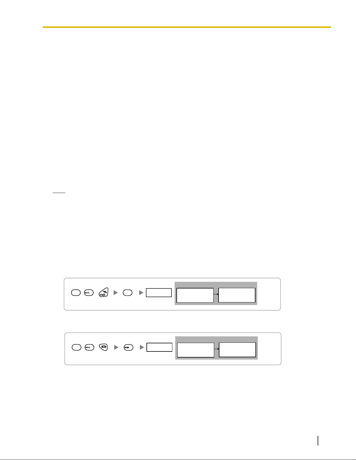
3. Conduct the site survey
Refer to "5 Site Survey".
a. Test the radio signal strength using the PS.
Confirm that the radio signal strength level is "12" near the CS.
Using the KX-TD7684/KX-TD7694
Using the KX-TD7680
Document Version 2009-12 Quick Installation Guide 9
Page 10
Display example:
Press 1, 9, and POWER
for more than 2 seconds.
<< SEARCHING >>
CS NO.1 LEVEL:12
SAVE:0123456789
1 to 9
CS No.
1
9
9
2 Procedure Overview
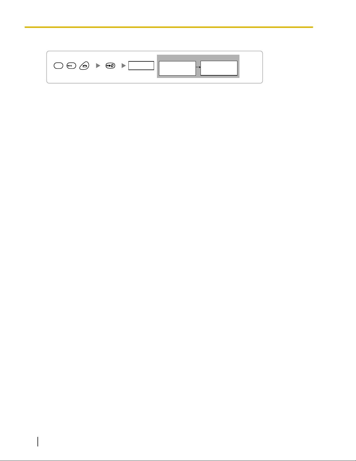
Using the KX-TD7690
b. By walking away from the CS with the PS, check the radio signal strength. The radio signal strength
weakens as you walk away from the CS.
c. Map the CS coverage area at radio signal strength levels "3" and "8".
d. Make sure that adjacent CS coverage areas overlap where the radio signal strength level is "8" by at least
5 m (16 ft).
e. Make sure that the radio signal strength level is greater than "3" at any location within the service area
required by the user.
4. Finish the site survey
Refer to "6 After Site Survey".
a. Turn off the PS.
b. Stop supplying power, and return all DIP switches of each CS to the OFF position.
5. Connect the CS and PS to the PBX and test the operation
Refer to "7 Connecting a Cell Station to the PBX".
a. Connect the CSs to the PBX.
b. Register the PSs to the PBX.
c. Walk around the service area while having a conversation using a registered PS. If noise is frequent or
conversations disconnect, relocate the CSs or install an additional CS.
6. Mount the CS on the wall
Refer to "8 Wall Mounting".
a. If there are no problems in testing, mount the CS on the wall.
10 Quick Installation Guide Document Version 2009-12
Page 11
CS
Column
3. Penetration
2. Diffraction
1. Reflection
3 Site Planning
3 Site Planning
Choosing the best site for the CS requires careful planning and testing of essential areas. The best location
may not always be convenient for installation. Read the following information before installing the unit.
Understanding Radio Waves
Characteristics of Radio Waves
The transmission of radio waves and the CS coverage area depend on the structure and materials of the
building.
Office equipment, such as computers and fax machines, can interfere with radio waves. Such equipment may
create noise or interfere with the performance of the PS.
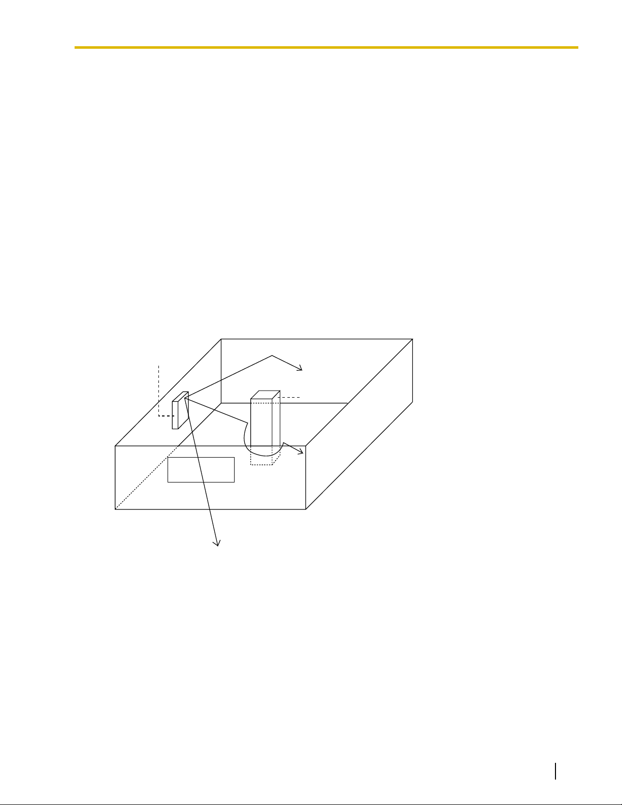
The illustration below shows the special transmitting patterns of radio waves.
1. Radio waves are reflected by objects made of materials such as metal.
2. Radio waves are diffracted by objects such as metallic columns.
3. Radio waves penetrate objects made of materials such as glass.
Relationships between Radio Waves and Building Structure and Materials
• The CS coverage area is affected more by the building materials and their thickness than the number of
obstacles.
• Radio waves tend to be reflected or diffracted by conductive objects and rarely penetrate them.
• Radio waves tend to penetrate insulated objects and are rarely reflected by them.
• Radio waves penetrate thin objects more than thick objects.
• The table below shows the transmission tendency of radio waves when they reach objects made from
various materials.
Document Version 2009-12 Quick Installation Guide 11
Page 12
3 Site Planning
Wall Concrete The thicker they are, the less radio waves penetrate
Window Glass Radio waves usually penetrate them.
Object Material Transmission Tendency
them.
Ferroconcrete Radio waves can penetrate them, but the more iron
there is, the more radio waves are reflected.
Glass with wire net Radio waves can penetrate them, but tend to be
reflected.
Glass covered with
heat-resistant film
Radio waves are weakened considerably when they
penetrate windows.
Floor Ferroconcrete Radio waves can penetrate them, but the more iron
there is, the more radio waves are reflected.
Partition Steel Radio waves are reflected and rarely penetrate them.
Plywood, Glass Radio waves usually penetrate them.
Column Ferroconcrete Radio waves can penetrate them, but the more iron
there is, the more radio waves tend to be reflected or
diffracted.
Metal Radio waves tend to be reflected or diffracted.
Cabinet Steel Radio waves are usually reflected or diffracted, and
rarely penetrate them.
Wood Radio waves can penetrate them, but they are
weakened.
12 Quick Installation Guide Document Version 2009-12
Page 13

Gray Zone:
Conversation will be
intermittent
Coverage Area
Radio signal strength level is
greater than "3".
(About 50 m to 60 m
[164 ft to 197 ft])
Good Coverage Area
Radio signal strength
level is greater than "8".
(About 30 m to 40 m
[98 ft to 131 ft])
Good sound quality
can be maintained.
Out of Service:
Cannot make/receive calls
A
B
A
B
Radio Signal Strength Levels
C
Better
Good
May receive noise
Receives noise easily or disconnects
Out of range
Level: 11 to 12
Level: 08 to 10
Level: 03 to 07
Level: 01 to 02
Level: 00
3 Site Planning
CS Coverage Area
The example below shows the size of the coverage area of 1 CS if it is installed in an area with no obstacles.
Note
Radio signal strength levels are measured during the site survey (refer to "5 Site Survey").
Site Survey Preparation
1. Obtain a map and investigate the installation site.
a. Check the obstacles (e.g., shelves, columns, and partitions).
b. Check the materials of the structures (e.g., metal, concrete, and plywood).
c. Check the layout and dimensions of the room, corridor, etc.
d. Write down the above information on the map.
2. Examine the service area required by the user on the map, referring to the following example.
a. Draw the coverage area around a CS. Extend the coverage area 30 m to 60 m (98 ft to 197 ft) in each
direction, depending on the materials of the building structures and obstacles in the installation site.
Note that a CS cannot be installed outside a building.
Document Version 2009-12 Quick Installation Guide 13
Page 14

70 m
(230 ft)
CS no. 2
CS no. 4
150 m
(492 ft)
CS no. 5
CS no. 1
CS no. 3
3 Site Planning
b. If 1 CS cannot cover the entire service area, install additional CSs as required. Overlap the coverage
areas of adjacent CSs.
Where CS coverage areas overlap, the PS will start call handover to the next CS if the signal from one
CS becomes weak. However, if a PS moves away from a CS and there are no CSs available for
handover, the PS may go out of range and the call could be lost.
If the signal from the CS fades, due to the structure of the building, there may be some handover delay.
The user will hear a range warning before handover in this case. This also applies in the case of
interference from 2.4 GHz apparatus.
Example: Installing in a Room Separated by Interior Walls
Things to take note of:
• The room is separated by interior walls.
• The room is surrounded by concrete walls.
CS installation plan:
• The coverage area of each CS will not extend as far as when there are no obstacles, because the radio
signals will be weakened by separating walls. Therefore, you will need 5 CSs to cover the entire room.
14 Quick Installation Guide Document Version 2009-12
Page 15

4 Before Site Survey
12 34 5 6
4
4
4
4
4
4
4
4
4
3
3
3
3
3
3
3
3
3
2
2
2
2
2
2
2
2
2
1
1
1
1
1
1
1
1
1
CS no. 1
CS no. 2
CS no. 3
CS no. 4
CS no. 5
CS no. 6
CS no. 7
CS no. 8
CS no. 9
DIP Switch
Radio Signal Test Switch
Power Supply Select Switch
CS Number Switch
ON: From the AC Adaptor (KX-A11/KX-TCA1)/
Battery Box (PSZZTD142CE)
OFF: From the PBX
OFF
ON
Setting and Installing the CS Temporarily for Site Survey
1. Switch the Radio Signal Test switch from OFF to ON.
2. Set the CS number switches as desired.
3. Set the Power Supply Select switch as desired (KX-T0151/KX-TDA0152 only).
KX-T0151/KX-TDA0152
4 Before Site Survey
Document Version 2009-12 Quick Installation Guide 15
Page 16

CS Number Switch
CS no. 1 CS no. 2 CS no. 3 CS no. 4 CS no. 5 CS no. 6 CS no. 7 CS no. 8 CS no. 9
1
2
3
4
1
2
3
4
1
2
3
4
1
2
3
4
1
2
3
4
1
2
3
4
1
2
3
4
1
2
3
4
1
2
3
4
DIP Switch
1
2
3
4
5
6
OFF ON
Radio Signal
Test Switch
Keep this switch at the default
"OFF" position. Otherwise, the
CS will not function.
4 Before Site Survey
KX-T0141/KX-TDA0142
Note
If more than 1 CS is in Radio Signal Test mode, each CS must have a unique CS number.
4. After setting the DIP switches, connect the CS to an AC adaptor/battery box using a power supply adaptor,
or connect it to the PBX.
WARNING
When installing or testing a product with an external AC adaptor, the AC adaptor should be
plugged into a wall outlet or floor-mounted AC outlet. Do not connect the AC adaptor to a
ceiling-mounted AC outlet, as the weight of the adaptor may cause it to become disconnected.
Notice
If the Power Supply Select switch is set to ON in step 3, connect the CS to an AC adaptor/battery box.
If it is set to OFF, connect the CS to the PBX (KX-T0151/KX-TDA0152 only).
16 Quick Installation Guide Document Version 2009-12
Page 17

To AC Adaptor (KX-A11/KX-TCA1)/
Battery Box (PSZZTD142CE)
Power Supply Adaptor
(PSZZ1TDA0142)
RJ11 Modular
Telephone Cord
To PBX
RJ11 Modular
RJ11 Modular
To AC Adaptor (KX-A11/KX-TCA1)/
Battery Box (PSZZTD142CE)
Power Supply Adaptor
(PSZZ1TDA0142)
RJ11 Modular
Telephone Cord
RJ11 Modular
4 Before Site Survey
KX-T0151/KX-TDA0152
KX-T0141/KX-TDA0142
Document Version 2009-12 Quick Installation Guide 17
Page 18

At least 2 m
(6 ft 7 in)
45º
45º
90º
4 Before Site Survey
5. Install the CS temporarily for the site survey. Install the CS at least 2 m (6 ft 7 in) above the floor, and place
the antennas so that they are pointing in directions that are 90 degrees apart (for antenna diversity), as
follows:
Note
The illustration of the CS is based on the KX-T0151/KX-TDA0152.
18 Quick Installation Guide Document Version 2009-12
Page 19

<< SEARCHING >>
CS NO.1 LEVEL:12
*1
SAVE:0123456789
*2
1
9
9
0
Press 1, 9, and POWER
for more than 2 seconds.
1 to 9
CS No.
Scan Data No.
0 to 9
Display example:
To store the scan data
Display example:
Press 1, 9, and POWER
for more than 2 seconds.
<< SEARCHING >>
CS NO.1 LEVEL:12
*1
SAVE:0123456789
*2
1 to 9
CS No.
1
9
9
0 to 9
Scan Data No.
To store the scan data
0
Display example:
Press 1, 9, and POWER
for more than 2 seconds.
<< SEARCHING >>
CS NO.1 LEVEL:12
*1
SAVE:0123456789
*2
1 to 9
CS No.
1
9
9
0 to 9
Scan Data No.
To store the scan data
0
5 Site Survey
5 Site Survey
The PS has a Radio Signal Test mode that monitors the state of the radio link to the CS. After installing the
CSs temporarily, set the PS to Radio Signal Test mode and measure each CS coverage area. Then, record
the results on the map of the installation site.
Testing the Radio Signal Strength
Note
Display prompts for the site survey are only available in English.
1. Enter Radio Signal Test mode.
Using the KX-TD7684/KX-TD7694
Using the KX-TD7680
Using the KX-TD7690
Document Version 2009-12 Quick Installation Guide 19
Note
*1: CS number and radio signal strength level.
*2: Scan data (test result) number. Empty memory space will be indicated by a number; stored memory
space will be indicated by a "-".
Page 20

CS no. 1
PS
PS
PS
CS NO.1 LEVEL:3
CS NO.1 LEVEL:12
Radio Signal Strength Levels
CS NO.1 LEVEL:8
Level: 11 to 12
Level: 08 to 10
Level: 03 to 07
Level: 01 to 02
Level: 00
Better
Good
May receive noise
Receives noise easily or disconnects
Out of range
5 m to 10 m
(16 ft to 33 ft)
CS no. 1 CS no. 2
5 Site Survey
2. Measure the radio signal strength by moving towards and away from the CS.
a. Move to the CS until the radio signal strength level becomes "12".
b. Move away from the CS and identify the CS coverage area within which the radio signal strength level
is greater than "8". Draw the area on the map.
c. Move away from the CS and identify the CS coverage area within which the radio signal strength level
is greater than "3". Draw the area on the map.
3. Repeat steps 1 and 2 for other CSs, and relocate the CSs when necessary.
a. Overlap adjacent CS coverage areas where the radio signal strength level is "8" by 5 m to 10 m (16 ft
to 33 ft).
20 Quick Installation Guide Document Version 2009-12
Page 21

b. Overlap the CS coverage areas of at least 2 CSs at any location in the installation site.
CS no. 1 CS no. 2
CS no. 3
CS no. 4
1
9
9
1
NO.1
CS No.2 LEVEL: 9
NO.0
NOT SAVED
Press 1, 9, and POWER
for more than 2 seconds.
0 to 9
To the Desired Scan Data No.
Scan Data No.
Display example:
When there is scan data
When there is no scan data
Press 1, 9, and POWER
for more than 2 seconds.
0 to 9
Scan Data No.
1
9
9
1
Display example:
When there is scan data
When there is no scan data
NO.1
CS No.2 LEVEL: 9
NO.0
NOT SAVED
To the Desired Scan Data No.
5 Site Survey
c. Make sure that the radio signal strength level is greater than "3" at any location in the service area
required by the user.
Referring to the Stored Scan Data
Using the KX-TD7684/KX-TD7694
Using the KX-TD7680
Document Version 2009-12 Quick Installation Guide 21
Page 22

Press 1, 9, and POWER
for more than 2 seconds.
0 to 9
Scan Data No.
1
9
9
1
Display example:
When there is scan data
When there is no scan data
NO.1
CS No.2 LEVEL: 9
NO.0
NOT SAVED
To the Desired Scan Data No.
1
9
9
2
2
Press 1, 9, and POWER
for more than 2 seconds.
0 to 9, or # for all data
To the Desired Scan Data No.
Scan Data No.
Press 1, 9, and POWER
for more than 2 seconds.
0 to 9, or # for all data
Scan Data No.
1
9
9
To the Desired Scan Data No.
2
Press 1, 9, and POWER
for more than 2 seconds.
0 to 9, or # for all data
Scan Data No.
1
9
9
To the Desired Scan Data No.
2
5 Site Survey
Using the KX-TD7690
Deleting the Stored Scan Data
Using the KX-TD7684/KX-TD7694
Using the KX-TD7680
Using the KX-TD7690
22 Quick Installation Guide Document Version 2009-12
Page 23

12345 6
OFF
ON
1
2
3
4
5
6
OFF ON
6 After Site Survey
6 After Site Survey
After obtaining the proper measurement results, exit Radio Signal Test mode before connecting the CS to the
PBX.
1. Hold down the POWER button on the PS until the PS is turned OFF.
2. Disconnect the CS from the AC adaptor/battery box or the PBX to stop supplying electricity.
KX-T0151/KX-TDA0152 KX-T0141/KX-TDA0142
3. Switch all DIP switches on the CS from ON to OFF.
KX-T0151/KX-TDA0152
KX-T0141/KX-TDA0142
Document Version 2009-12 Quick Installation Guide 23
Page 24

Signal Name
Signal Name
Pin No.
1
2
3
4
D1
D2
D1
D2
Pin No.
1
2
3
4
A Super Hybrid Port (Hybrid Port),
or HLC4/DLC4/DLC8 card (RJ11)
CS (RJ11)
Cable Maximum Distance
26 AWG: 222 m (728 ft)
24 AWG: 347 m (1138 ft)
22 AWG: 500 m (1640 ft)
CAT 5: 347 m (1138 ft)
7 Connecting a Cell Station to the PBX
7 Connecting a Cell Station to the PBX
Connection Example for KX-TAW848/KX-TDA50
Refer to the following example to connect a CS to the PBX.
KX-T0151/KX-T0141 connecting to KX-TAW848/KX-TDA50
Accessories and User-supplied Items for the CS
Accessories (included): Screws ´ 2, Washers ´ 2
User-supplied (not included): RJ11 connector
Note
For details about the Super Hybrid Ports (Hybrid Ports) or HLC4/DLC4/DLC8 card, refer to the
Installation Manual for your PBX.
24 Quick Installation Guide Document Version 2009-12
Page 25

CSIF8 Card
1
2
3
4
D1
POWH
POWL
D2
D1
POWH
POWL
D2
1
2
3
4
5
6
7
8
Port 1
Maximum Distance
444 m (1457 ft)
694 m (2277 ft)
1000 m (3281 ft)
694 m (2277 ft)
Cable
26 AWG:
24 AWG:
22 AWG:
CAT 5:
CS (RJ11)
Pin No.
Signal Name
CSIF card (RJ45)
Pin No.
Signal Name
7 Connecting a Cell Station to the PBX
Connection Examples for KX-TDA100/KX-TDA200/KX-TDA600/KX-TDE100/
KX-TDE200/KX-TDE600
Refer to the following examples to connect a CS to the PBX.
KX-TDA0152/KX-TDA0142 connecting to KX-TDA100/KX-TDA200/KX-TDA600/KX-TDE100/
KX-TDE200/KX-TDE600
Note
The illustration of the PBX is based on the KX-TDE200.
Accessories and User-supplied Items for the CS
Accessories (included): Screws ´ 2, Washers ´ 2
User-supplied (not included): RJ11 connector
Note
For details about the CSIF card, refer to the Installation Manual for your PBX.
Document Version 2009-12 Quick Installation Guide 25
Page 26

Cable
26 AWG:
24 AWG:
22 AWG:
CAT 5:
Maximum Distance
222 m (728 ft)
347 m (1138 ft)
500 m (1640 ft)
347 m (1138 ft)
D1
D2
Signal Name
DHLC/DLC card (Amphenol)
1
2
3
4
D1
D2
CS (RJ11)
Pin No.
Signal Name
DHLC8 Card
7 Connecting a Cell Station to the PBX
KX-T0151/KX-T0141 connecting to KX-TDA100/KX-TDA200/KX-TDA600/KX-TDE100/
KX-TDE200/KX-TDE600
Note
The illustration of the PBX is based on the KX-TDE200.
Accessories and User-supplied Items for the CS
Accessories (included): Screws ´ 2, Washers ´ 2
User-supplied (not included): RJ11 connector
Note
For details about DHLC/DLC card, refer to the Installation Manual for your PBX.
26 Quick Installation Guide Document Version 2009-12
Page 27

Connection Example for KX-NCP500/KX-NCP1000
Signal Name
DHLC/DLC card (RJ45)
Pin No.
1
2
3
4
5
6
7
8
D1
D2
1
2
3
4
D1
D2
CS (RJ11)
Pin No.
Signal Name
DHLC4 Card
Cable
26 AWG:
24 AWG:
22 AWG:
CAT 5:
Maximum Distance
222 m (728 ft)
347 m (1138 ft)
500 m (1640 ft)
347 m (1138 ft)
Refer to the following example to connect a CS to the PBX.
KX-T0151/KX-T0141 connecting to KX-NCP500/KX-NCP1000
Note
The illustration of the PBX is based on the KX-NCP500.
7 Connecting a Cell Station to the PBX
Document Version 2009-12 Quick Installation Guide 27
Accessories and User-supplied Items for the CS
Accessories (included): Screws ´ 2, Washers ´ 2
User-supplied (not included): RJ11 connector
Note
For details about the DHLC/DLC card, refer to the Installation Manual for your PBX.
Page 28

RJ11 Modular
To PBX
RJ11 Modular
To PBX
To PBX
To PBX
7 Connecting a Cell Station to the PBX
Connecting the CS
1. Connect the cable from the PBX to the CS.
KX-T0151/KX-TDA0152
KX-T0141/KX-TDA0142
2. Pass the cable through the groove of the CS (in any direction depending on your preference).
KX-T0151/KX-TDA0152
KX-T0141/KX-TDA0142
28 Quick Installation Guide Document Version 2009-12
Page 29

#
1234
System Password for Administrator—
for PT Programming
Programming No.
3 digits
PROGRAM/
PAUSE
Press POWER
for 2 seconds.
Select
"Setting Handset".
Select
"System Option".
If required
4 digits
System Lock Password
System Setting Menu
System Setting Menu
Select
"SYSTEM SET".
Press POWER
for 2 seconds.
Select
"PS PROGRAM".
4 digits
System Lock Password
If required
FUNC
FUNC
System Setting Menu
Select
"SYSTEM SETTING".
Press POWER
for 2 seconds.
S1 S1
MENU SEL
S1
SEL
Select
"PS PROGRAM".
4 digits
System Lock Password
If required
ENTR
S1
7 Connecting a Cell Station to the PBX
Registering the PS
The PS must be registered to the PBX before it can be used. Programming of both the PS and PBX is required.
A Proprietary Telephone (PT) with multiline display (e.g., KX-T7636 6-line display) is required to perform the
PBX system programming.
Note
For details about system programming using a PT, refer to "PT Programming" in the Feature Manual,
and "PT Programming" in the PT Programming Manual for your PBX.
Entering the System Programming Mode
PT (Administrator Level)
PS (Using the KX-TD7684/KX-TD7694)
PS (Using the KX-TD7680)
PS (Using the KX-TD7690)
Note
Document Version 2009-12 Quick Installation Guide 29
means default value throughout this section.
Page 30

[692]
4 digits
PIN for PS Registration
END
(HOLD)
ENTER ENTER
1234
Select
"Change PIN"
1 to 8 digits
1234
C.Tone
PIN for PS Registration
Select
"CHANGE PIN"
C.Tone
1 to 4 digits
1234
PIN for PS Registration
Select
"CHANGE PIN"
S1
ENTR
S1
SEL
C.Tone
1 to 4 digits
1234
PIN for PS Registration
[690]
001 to max. no.
of PSs (3 digits)
PS No.
1 to 5 digits
END
(HOLD)
ENTER ENTER
To the PS
operation
below
Extn. No.
7 Connecting a Cell Station to the PBX
Setting the Personal Identification Number (PIN) for PS Registration
To prevent registering the PS to a wrong PBX, a PIN for PS registration can be set to the PBX. Before
registering the PS to the PBX, enter the PIN set to the PBX into the PS. By doing so, the PS will only be
registered to the PBX with the matching PIN.
CAUTION
To avoid unauthorized access and possible abuse of the PBX, we strongly recommend:
a. Keeping the password (PIN for PS registration) secret.
b. Not using the default password and changing the password regularly.
c. Selecting a complex, random password that cannot be easily guessed.
Note
The PIN for PS registration will only be used when registering the PS to the PBX. Therefore, during
normal operation after registration, even if there is more than 1 PBX with the same PIN near the PS,
the PS will not be inadvertently linked to a different PBX.
Setting the PIN for PBX
Setting the PIN for PS
Using the KX-TD7684/KX-TD7694
Using the KX-TD7680
Using the KX-TD7690
PS Registration
30 Quick Installation Guide Document Version 2009-12
When the PS has not been registered yet
When registering the PS for the first time, it is possible to select the desired language for the display. (You
do not need to enter the PS system programming mode when registering for the first time.)
Page 31

Using the KX-TD7684/KX-TD7694
Press
POWER for
2 seconds.
Select the desired
language
.
Press "F"
for 2
seconds.
C.Tone C.Tone
Press
POWER for
2 seconds.
Press S3
for 2
seconds.
C.Tone
Press S2 repeatedly
to select the desired
language.
[ F2 ]
[ F3 ]
Press
POWER for
2 seconds.
Press S3
for 2
seconds.
C.Tone
Press S2 repeatedly
to select the desired
language.
F2
F3
Choose
"Base 1–4".
Select
"
Register H/S
".
C.Tone
Choose
"SYSTEM 1–4".
Select
"REGISTRATION".
C.Tone
Choose
"SYSTEM 1–4".
Select
"REGISTRATION".
S1S1
SEL SEL
C.Tone
Using the KX-TD7680
Using the KX-TD7690
7 Connecting a Cell Station to the PBX
When the PS has already been registered to another PBX
One PS can be registered to a maximum of 4 different PBXs.
Using the KX-TD7684/KX-TD7694
Using the KX-TD7680
Using the KX-TD7690
Setting the System Lock
Document Version 2009-12 Quick Installation Guide 31
After PS registration, it is possible to set a 4-digit system lock password to prevent unauthorized access
to PS system settings. When system lock is enabled, the system lock password will be required to access
PS system settings.
CAUTION
To avoid unauthorized access and possible abuse of the PBX, we strongly recommend:
Page 32

Select
"System Lock".
4 digits
4 digits
Choose "On/Off".
On
Off
C.Tone
System Lock Password
System Lock Password
Choose
"Enable/Disable".
Select
"SYSTEM LOCK".
C.Tone
4 digits
4 digits
ENABLE
DISABLE
System Lock Password
System Lock Password
S1
Choose
"Enable/Disable".
SEL
ENTR
S1
S1
S1
S1
CHNG
SEL
ENTR
Select
"SYSTEM LOCK".
C.Tone
System Lock Password System Lock Password
4 digits
4 digits
ENABLE
DISABLE
7 Connecting a Cell Station to the PBX
a. Keeping the password secret.
b. Changing your password regularly.
c. Selecting a complex, random password that cannot be easily guessed.
Using the KX-TD7684/KX-TD7694
Using the KX-TD7680
PS Termination
32 Quick Installation Guide Document Version 2009-12
Using the KX-TD7690
Confirm the following before canceling the PS registration:
• The PS is turned on.
Page 33

[691]
001 to max. no.
of PSs (3 digits)
PS No.
ENTER ENTER
END
(HOLD)
If "Rejected" or "Time out" is displayed
CLEAR YES
Press "YES".Press "CLEAR".
Select "Base 1-4".
Select "Yes".
C.Tone
Select "Cancel Base".
Select the
desired item.
Select "DELETE
SYSTEM".
Select "YES".
C.Tone
Select the
desired item.
Select "DELETE
SYSTEM".
S1S1
SEL SEL
Select "YES".
C.Tone
S1
SEL
7 Connecting a Cell Station to the PBX
• The PS is within range.
If "Rejected" or "Time out" is displayed
The registration information is still stored in the PS. You need to delete the registration information from
the PS.
Using the KX-TD7684/KX-TD7694
Using the KX-TD7680
Using the KX-TD7690
Testing the Operation
Walk around the service area while having a conversation using a registered PS. If noise is frequent or
conversations disconnect, relocate the CSs or install an additional CS.
Document Version 2009-12 Quick Installation Guide 33
Page 34

Ta bs
Wall Mounting Plate
(PSKL1032Y4)
8 Wall Mounting
8 Wall Mounting
Mounting the KX-T0151/KX-TDA0152
WARNING
• Make sure that the wall that the unit will be attached to is strong enough to support the unit
(approx. 310 g [11 oz]). If not, it is necessary for the wall to be reinforced.
• Only use the wall-mounting equipment (screws, washers, wall mounting plate) included with
the unit.
• When this product is no longer in use, make sure to detach it from the wall.
CAUTION
• When driving the screws into the wall, be careful to avoid touching any metal laths, wire laths or metal
plates in the wall.
• Do not stretch or bend the cables. Also, do not allow anything to rest on the cables.
• Use cables that are fire-resistant or fireproof.
• The CS and the cables should never be placed near or over a radiator or other heat source.
• Do not bundle cables that are connected to the CS with the AC power cords of machines located
nearby.
• Make sure the cables are securely fastened to the wall.
1. Place the reference for wall mounting (KX-T0151/KX-TDA0152) on the wall to mark the 2 screw positions.
2. Install the 2 screws and washers (included) into the wall.
Note
• Make sure that the screw heads are at the same distance from the wall.
• Install the screws perpendicular to the wall.
3. Insert the upper and lower tabs of the wall mounting plate into the designated openings in the base unit.
34 Quick Installation Guide Document Version 2009-12
Page 35

4. Slide the wall mounting plate in the direction of the arrow until it clicks.
Washer
Drive the screw
to this point.
45º
45º
90º
5. Hook the CS on the screw heads.
8 Wall Mounting
6. Place the antennas so that they are pointing in directions that are 90 degrees apart (for antenna diversity),
as follows:
Document Version 2009-12 Quick Installation Guide 35
Page 36

Install a screw here.
Install a screw here.
83 mm
(3-1/4 in)
100 mm
(3-15/16 in)
8 Wall Mounting
Reference for Wall Mounting (KX-T0151/KX-TDA0152)
Please copy this page and use as a reference for wall mounting.
Note
36 Quick Installation Guide Document Version 2009-12
Make sure to set the print size to correspond with the size of this page. If the dimension of the paper output
still deviates slightly from the measurement indicated here, use the measurement indicated here.
Page 37

Washer
Drive the screw
to this point.
8 Wall Mounting
Mounting the KX-T0141/KX-TDA0142
WARNING
• Make sure that the wall that the unit will be attached to is strong enough to support the unit
(approx. 310 g [11 oz]). If not, it is necessary for the wall to be reinforced.
• Only use the wall-mounting equipment (screws, washers) included with the unit.
• When this product is no longer in use, make sure to detach it from the wall.
CAUTION
• When driving the screws into the wall, be careful to avoid touching any metal laths, wire laths or metal
plates in the wall.
• Do not stretch or bend the cables. Also, do not allow anything to rest on the cables.
• Use cables that are fire-resistant or fireproof.
• The CS and the cables should never be placed near or over a radiator or other heat source.
• Do not bundle cables that are connected to the CS with the AC power cords of machines located
nearby.
• Make sure the cables are securely fastened to the wall.
1. Place the reference for wall mounting (KX-T0141/KX-TDA0142) on the wall to mark the 2 screw positions.
2. Install the 2 screws and washers (included) into the wall.
Note
• Make sure that the screw heads are at the same distance from the wall.
• Install the screws perpendicular to the wall.
3. Hook the CS on the screw heads.
Document Version 2009-12 Quick Installation Guide 37
Page 38

45º
45º
90º
Install a screw here.
Install a screw here.
71 mm
(2-13/16 in)
8 Wall Mounting
4. Place the antennas so that they are pointing in directions that are 90 degrees apart (for antenna diversity),
as follows:
Reference for Wall Mounting (KX-T0141/KX-TDA0142)
Please copy this page and use as a reference for wall mounting.
Note
Make sure to set the print size to correspond with the size of this page. If the dimension of the paper output
still deviates slightly from the measurement indicated here, use the measurement indicated here.
38 Quick Installation Guide Document Version 2009-12
Page 39

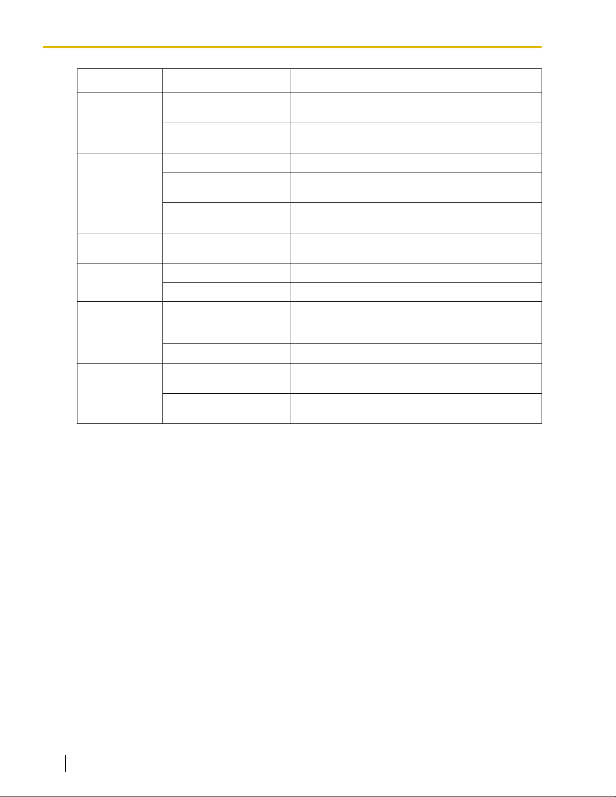
9 Troubleshooting
PROBLEM PROBABLE CAUSE SOLUTION
9 Troubleshooting
• The LED of the CS does not
change to Green ON.
• The optional service card is
not working.
• CS is not connected
properly.
• CS is not set for normal
operation.
• The status of the port that
the CS is connected to is
Out of Service.
• The LED of the CS stays
Red ON during normal
operation.
• CS malfunction • Replace the CS.
• Cannot register the PS. • Wrong Personal
Identification Number (PIN)
is registered to the PS.
• PS becomes out of range.
• Cannot make calls using
the PS.
• Location of CS is not good.
• Access system of the PS is
not properly set.
• Install the card properly.
• Make sure that the cable is connected
properly with correct pin assignments.
Also, make sure that the cable does not
make short circuits.
• Switch all DIP switches off.
• Change the port status from Out of
Service to In Service using the
Maintenance Console.
• Enter the PIN set to the PBX into the
PS.
• Locate the CS properly (refer to "5 Site
Survey").
• Change the access system setting of
the PS to the appropriate system or
automatic.
• Noise is frequent while
using the PS.
• Conversations disconnect
while using the PS.
• "NO SERVICE" is displayed
on the PS's screen.
• The CS is not busy (i.e., the
status of the LED is not
Moderate Green Flashing),
but calls cannot be made or
received.
• There is noise during a
phone call.
• PS stays out of service
when the CS status is
changed from Out of
Service to In Service.
• Call handover is not
working.
• PS is out of CS coverage
area.
• CSs are located too close
together in the same area.
• It may take about 20 s for
the CS to start up after the
status has been changed
to In Service.
• Locate the CS properly (refer to "5 Site
Survey").
• Reduce the number of CSs in the area,
or increase the distance between CSs
(refer to "5 Site Survey").
• Wait until the CS starts up.
Document Version 2009-12 Quick Installation Guide 39
Page 40

One Panasonic Way, Secaucus, New Jersey 07094
http://www.panasonic.com/csd
Copyright:
This material is copyrighted by Panasonic System Networks Co., Ltd., and may be reproduced for internal
use only. All other reproduction, in whole or in part, is prohibited without the written consent of Panasonic
System Networks Co., Ltd.
© Panasonic System Networks Co., Ltd. 2009
PSQX5041ZA KK1209NT0 (v0.004)
 Loading...