

Page 1

Operating Instructions
Model No. KX-PS8100
Please carefully read the Operating Instructions and the Utilities and Drivers Reference Guide before using
the Digital Color Imaging System. Keep this CD-ROM in the protective case. Do not expose the CD-ROM to
direct sunlight or extreme heat and do not scratch or smudge the surface of the CD-ROM.
Page 2

Thank you for purchasing the Panasonic Digital Color Imaging System (DCIS) KX-PS8100.
The Panasonic Digital Color Imaging System KX-PS8100 consists of the Color Laser Printer
KX-PS8101 and the Color Scanner KX-PS8102.
The serial numbers are located on the labels on the rear of the units. For your convenience, record these
numbers below and keep this book along with your proof of purchase, in the event of a theft or for future
reference.
MODEL NO. Printer: KX-PS8101 Scanner: KX-PS8102
SERIAL NO. Printer: Scanner:
NAME OF RESELLER
DATE OF PURCHASE
Important
•
Do not duplicate bills, coins, securities and the like (with this system).
•Do not duplicate copyrighted material or the work of others except for the purpose of private use.
•Do not duplicate any kind of certificates, licenses, passports, official or private documents, and the
like.
2
Page 3

As an E
the E
NERGY
(E
NERGY
Adobe, Acrobat, Adobe Photoshop, Adobe Illustrator, PostScript, PostScript 3,
Adobe Type Manager and the PostScript 3 logo are trademarks of Adobe Systems
Incorporated.
Fiery, Fiery Driven, the Fiery Driven, and ColorWise logo are trademarks owned by
Electronics For Imaging and registered with the U.S. Patent and Trademark Office
and in certain other foreign jurisdictions.
•
Fiery WebTools, Fiery WebSpooler, Fiery WebLink, Fiery WebStatus, and VisualCal are trademarks of
Electronics For Imaging, Inc.
•
Apple, AppleTalk, LocalTalk, ColorSync, Macintosh, and TrueType are trademarks or registered trademarks
of Apple Computer, Inc.
•
IBM is a trademark of International Business Machines Corporation.
•
SunOS, Solaris and Java are trademarks or registered trademarks of Sun Microsystems, Inc. in the United
States and other countries.
•
QuarkXpress is a trademark of Quark, Inc.
•
CorelDRAW is a trademark of Corel Corporation.
•
Netscape and Netscape Navigator are trademarks of Netscape Communications Corporation.
•
NetWare, Novell and Internetwork Packet Exchange (IPX) are trademarks or registered trademarks of
Novell, Inc.
•
Times and Helvetica are trademarks of Linotype-Hell AG and/or its subsidiaries.
•
PANTONE is a trademark of Pantone, Inc.
•
UNIX is a trademark of X/Open Company, Ltd.
•
Microsoft, MS-DOS, Windows and Windows NT are registered trademarks of Microsoft Corporation in the
United States and/or other countries.
•
Pentium is a registered trademark of Intel Corporation.
•
Centronics is a trademark of Centronics Data Computer Corporation.
•
Adaptec is a registered trademark of Adaptec, Inc.
•
Avery is a registered trademark and all Avery codes are trademarks of Avery Dennison Corporation.
•
All other acknowledgments are trademarks or registered trademarks of their respective holders.
S
NERGY
S
S
TAR
® Partner, Panasonic has determined that this product meets
TAR
® guidelines for energy efficiency.
TAR
is a U.S. registered mark.)
Screen shots reprinted with permission from Microsoft Corporation.
Acrobat® Reader copyright ©1987-1997 Adobe Systems Incorporated. All rights reserved.
The operating instructions are subject to change without notice.
© Electronics For Imaging, Inc. 1999
© Kyushu Matsushita Electric Co., Ltd. 1999
3
Page 4

EFI STANDARD SOFTWARE LICENSE AGREEMENT
Electronics For Imaging, Inc. grants to you a non-exclusive, non-transferable license to use the software and
accompanying documentation (“Software”) included with the Fiery® server you have purchased, including
without limitation the PostScript® software provided by Adobe Systems Incorporated.
You may:
a.use the Software solely for your own customary business purposes and solely with the Fiery® server;
b.use the digitally-encoded machine-readable outline and bitmap programs (“Font Programs”) provided with
the Fiery® server in a special encrypted format (“Coded Font Programs”) to reproduce and display designs,
styles, weights, and versions of letters, numerals, characters and symbols (“Typefaces”) solely for your own
customary business purposes on the screen of the Fiery® server or Macintosh monitor used with the Fiery®
server;
c.use the trademarks used by Electronics For Imaging to identify the Coded Font Programs and Typefaces
reproduced therefrom (“Trademarks”); and
d.assign your rights under this Agreement to a transferee of all of your right, title and interest in and to the
Fiery® server provided the transferee agrees to be bound by all of the terms and conditions of this
Agreement.
You may not:
a.make use of the Software, directly or indirectly, to print bitmap images with print resolutions of 600 dots per
inch or greater, or to generate fonts or typefaces for use other than with the Fiery® server;
b.make or have made, or permit to be made, any copies of the Software, Coded Font Programs,
accompanying documentation or portions thereof, except as necessary for use with the Fiery® Server
purchased by you; provided, however, that under no circumstances may you make or have made, or permit
to be made, any copies of that certain portion of the Software which has been included on the Fiery® server
hard disk drive. You may not copy the documentation;
c.attempt to alter, disassemble, decrypt or reverse engineer the Software, Coded Font Programs or
accompanying documentation.
d.rent or lease the Software.
Proprietary Rights
You acknowledge that the Software, Coded Font Programs, Typefaces, Trademarks and accompanying
documentation are proprietary to Electronics For Imaging and its suppliers and that title and other intellectual
property rights therein remain with Electronics For Imaging and its suppliers. Except as stated above, this
Agreement does not grant you any right to patents, copyrights, trade secrets, trademarks (whether registered
or unregistered), or any other rights, franchises or licenses in respect of the Software, Coded Font Programs,
Typefaces, Trademarks or accompanying documentation. You may not adapt or use any trademark or trade
name which is likely to be similar to or confusing with that of Electronics For Imaging or any of its suppliers or
take any other action which impairs or reduces the trademark rights of Electronics For Imaging or its suppliers.
The trademarks may be used only to identify printed output produced by the Coded Font Programs. At the
reasonable request of Electronics For Imaging, you must supply samples of any Typeface identified with a
trademark. The MacApp software is proprietary to Apple Computer, Inc. and is licensed to Electronics For
Imaging, Inc. for distribution only for use in combination with Fiery® server software utilities.
Confidentiality
You agree to hold the Software and Coded Font Programs in confidence, disclosing the Software and Coded
Font Programs only to authorized users having a need to use the Software and Coded Font Programs as
permitted by this Agreement and to take all reasonable precautions to prevent disclosure to other parties.
4
Page 5

Remedies
Unauthorized use, copying or disclosure of the Software, Coded Font Programs, Typefaces, Trademarks or
accompanying documentation will result in automatic termination of this license and will make available to
Electronics For Imaging other legal remedies.
Limited Warranty And Disclaimer
Electronics For Imaging warrants that, for a period of ninety (90) days from the date of delivery to you, the
Software under normal use will perform without significant errors that make it unusable. Electronics For
Imaging’s entire liability and y our exclusive remedy under this warranty (which is subject to you returning Fiery
to Electronics For Imaging or an authorized dealer) will be, at Electronics For Imaging’s option, to use
reasonable commercial efforts to attempt to correct or work around errors, to replace the Software with
functionally equivalent software, or to refund the purchase price and terminate this Agreement. Some states do
not allow limitations on duration of implied warranty, so the above limitation may not apply to you.
Except for the abov e express limited w arranty, Electronics For Imaging makes and you receiv e no warr anties or
conditions on the Product, express, implied, or statutory, and Electronics For Imaging specifically disclaims any
implied warranty or condition of merchantability or fitness for a particular purpose.
For warranty service, please contact your authorized service/support center.
EXCEPT FOR THE ABOVE EXPRESS LIMITED WARRANTY, ELECTRONICS FOR IMAGING MAKES AND
Y OU RECEIVE NO WARRANTIES OR CONDITIONS ON THE SOFTWARE OR CODED FONT PR OGRAMS ,
EXPRESS, IMPLIED, STATUTORY, OR IN ANY OTHER PROVISION OF THIS AGREEMENT OR
COMMUNICATION WITH YOU, AND ELECTRONICS FOR IMAGING SPECIFICALLY DISCLAIMS ANY
IMPLIED WARRANTY OR CONDITION OF MERCHANTABILITY OR FITNESS FOR A PARTICULAR
PURPOSE. Electronics F or Imaging does not w arrant that the operation of the softw are will be uninterrupted or
error free or that the Software will meet your specific requirements.
Limitation Of Liability
IN NO EVENT WILL ELECTRONICS FOR IMAGING OR ITS SUPPLIERS BE LIABLE FOR ANY DAMAGES,
INCLUDING LOSS OF DATA, LOST PROFITS, COST OF COVER OR OTHER SPECIAL, INCIDENTAL,
CONSEQUENTIAL OR INDIRECT DAMAGES ARISING FROM THE USE OF THE SOFTWARE, CODED
FONT PROGRAMS OR ACCOMPANYING DOCUMENTA TION, HOWEVER CAUSED AND ON ANY THEORY
OF LIABILITY. THIS LIMITATION WILL APPLY EVEN IF ELECTRONICS FOR IMAGING OR ANY
AUTHORIZED DEALER HAS BEEN ADVISED OF THE POSSIBILITY OF SUCH DAMAGE. YOU
ACKNOWLEDGE THAT THE PRICE OF FIERY REFLECTS THIS ALLOCATION OF RISK. BECAUSE SOME
STATES/JURISDICTIONS DO NOT ALLOW THE EXCLUSION OR LIMITATION OF LIABILITY FOR
CONSEQUENTIAL OR INCIDENTAL DAMAGES, THE ABOVE LIMITATION MAY NOT APPLY TO YOU.
Export Controls
You agree that you will not export or re-export the Software or Coded Font Programs in any form without the
appropriate United States and foreign government licenses. Your failure to comply with this provision is a
material breach of this Agreement.
Government Use
Use, duplication or disclosure of the Software by the United States Government is subject to restrictions as set
forth in subdivision (c) (1) (ii) of the Rights in Technical Data and Computer Software clause at DFARS
252.227-7013 or in subparagraphs (c) (1) and (2) of the Commercial Computer Software—Restricted Right
Clause at 48 CFR 52.227-19, as applicable.
5
Page 6

Third Party Beneficiary
You are hereby notified that Adobe Systems Incorporated, a California corporation located at 1585 Charleston
Road, Mountain View, California 94039-7900 (“Adobe”) is a third-party beneficiary to this Agreement to the
extent that this Agreement contains provisions which relate to y our use of the F onts, the Coded F ont Programs ,
the Typefaces and the Trademarks licensed hereby. Such provisions are made expressly for the benefit of
Adobe and are enforceable by Adobe in addition to Electronics For Imaging.
General
This Agreement will be governed by the laws of the State of California.
This Agreement is the entire agreement held between us and supersedes any other communications or
advertising with respect to the Software, Coded Font Programs and accompanying documentation.
If any provision of this Agreement is held invalid, the remainder of this Agreement shall continue in full force
and effect.
If you have any questions, please see Electronics For Imaging’s web site at www.efi.com.
These functions are used for various tasks such as Desktop Publishing, or image editing.
6
Page 7

End-User License Agreement
THIS IS A LEGAL AGREEMENT BETWEEN YOU AND PANASONIC. CAREFULLY READ ALL THE TERMS
AND CONDITIONS OF THIS AGREEMENT PRIOR TO OPENING THE PACKET OF SOFTWARE
PROGRAM. OPENING THE PACKET INDICATES YOUR ACCEPTANCE OF THESE TERMS AND
CONDITIONS. If you do not agree to these terms and conditions, return the unopened packet and the other
components of the Panasonic product to the place of purchase and your money will be refunded. No refunds
will be given for the products that have an opened packet or missing components.
1. COPYRIGHT:
Panasonic has the right to license or has been granted to license the enclosed Software Program
(“SOFTWARE”), developed and copyrighted by Kyushu Matsushita Electric Co., Ltd. or its licensor (“Licensor”).
You acknowledge that you are receiving only a LIMITED LICENSE TO USE the SOFTWARE and related
documentation, and that you shall obtain no title, ownership nor any other rights in or to the SOFTWARE and
related documentation, all of which title and rights shall remain with Licensor and Panasonic.
2. LICENSE:
(1) You have the non-exclusive rights to use the SOFTWARE on your computer. (2) If you wish to use the
SOFTWARE in your network, you may install the SOFTWARE into a network server and/or its clients and use
the copies of SOFTWARE in your network. (3) You may make reasonable quantities of copies of the
SOFTWARE solely for backup or archival purposes. (4) You may not rent or lease the SOFTWARE, but you
may transfer your right under this License Agreement on a permanent basis, provided that you transfer this
Agreement, all copies of the SOFTWARE, all related documentation and your Panasonic product, and the
recipient thereof agrees to the terms of this Agreement. (5) You may not reverse engineer, decompile or
disassemble the SOFTWARE, except that in European Union and European Free Trade Association, you may
have the limited right to reverse engineer, decompile or disassemble the SOFTWARE solely to the extent
specifically permitted by the terms and conditions of Article 6 of the European Community’s Directive for the
Legal Protection of Computer Programs, OJL 122/42 (17 May 1991). (6) You may not use, copy, modify, alter or
transfer the SOFTWARE, any copy thereof or its related documentation, in whole or in part, except as
expressly provided in this Agreement.
3. TERM:
This license is effective until terminated. You may terminate this Agreement at any time by destroying the
SOFTWARE and related documentation and all copies thereof. This license will also terminate if you fail to
comply with any term or condition of this Agreement. Upon such termination, you agree to destroy all copies of
the SOFTWARE and related documentation.
4. LIMITED WARRANTY:
Within ninety (90) days of your receipt of the SOFTWARE, Panasonic warrants that the storage media on
which the SOFTWARE are furnished is free from defect in materials and workmanship under normal use, and
that it will repair or at its option replace any defective media at no charge to you, provided that such defective
media is returned to Panasonic within such ninety (90) days period.
7
Page 8

5. LIMITATION OF LIABILITY:
EXCEPT AS STA TED ABOVE, NEITHER PANASONIC NOR PANASONIC’S SUPPLIER MAKES OR PASSES
ON TO YOU OR OTHER THIRD PARTY, ANY WARRANTY OR REPRESENTATION INCLUDING, BUT NOT
LIMITED TO, THE IMPLIED WARRANTY OF MERCHANTABILITY AND FITNESS FOR A PARTICULAR
PURPOSE. WITHOUT LIMITING THE GENERALITY OF THE FOREGOING, NEITHER PANASONIC NOR
PANASONIC’S SUPPLIER WARRANTS THAT THE SOFTWARE WILL BE ERROR-FREE OR THAT IT WILL
MEET YOUR REQUIREMENTS. NEITHER PANASONIC NOR PANASONIC’S SUPPLIER SHALL BE LIABLE
FOR ANY DAMAGE SUFFERED BY YOU INCLUDING, BUT NOT LIMITED TO, CONSEQUENTIAL,
INCIDENTAL SPECIAL OR PUNITIVE DAMAGES. THE ABOVE LIMITA TIONS SHALL APPLY REGARDLESS
OF THE FORM OF ACTION WHETHER IN CONTRACT, TORT (INCLUDING NEGLIGENCE), STRICT
PRODUCT LIABILITY OR OTHERWISE, EVEN IF SUCH PARTY HAS BEEN ADVISED OF THE
POSSIBILITY OF SUCH DAMAGES.
8
Page 9

FOR USERS IN UNITED STATES
This equipment has been tested and found to comply with the limits for a Class B digital device, pursuant
to Part 15 of the FCC Rules. These limits are designed to provide reasonable protection against harmful
interference in a residential installation.
This equipment generates, uses, and can radiate radio frequency energy and, if not installed and used in
accordance with the instructions, may cause harmful interference to radio communications.
Howev er , there is no guar antee that interf erence will not occur in a particular installation. If this equipment
does cause harmful interference to radio or television reception, which can be determined by
turning the equipment off and on, the user is encouraged to try to correct the interference by one or more
of the following measures:
•Reorient or relocate the receiving antenna.
•Increase the separation between the equipment and receiver.
•Connect the equipment into an outlet on a circuit different from that to which the receiver is connected.
•Consult the dealer or an experienced radio/TV technician for help.
The user may find the booklet “Something About Interference” available from FCC local regional offices
helpful.
FCC Warning: To assure contin ued FCC emission limit compliance, the user must use the recommended
shielded interfacing cable when connecting to a host computer. Also, any unauthorized changes or
modifications to this equipment would void the user’s authority to operate this device.
Technical Support Calls
If you have read this manual and tried the troubleshooting procedures and you are still having difficulty,
please contact the reseller from which the unit was purchased. You may also call the end user technical
support telephone number which is operational during East Coast business hours (9:00 AM to 7:00 PM).
The end user technical support number is 1-888-744-2424.
This number is available within the U.S. only.
Helpful Phone Numbers
To locate your nearest sales dealer CALL 1-800-742-8086 ask for COLOR
To order consumables CALL 1-800-222-0584
To order operating instructions/CD’s CALL 1-800-833-9626
To locate your nearest authorized service center CALL 1-888-744-2424
For technical support CALL 1-888-744-2424
Automated 24-hour support via Fax back CALL 1-800-222-0584
Electronic bulletin board CALL 1-201-863-7845
World Wide Web Technical & Driver Support http://www.panasonic.com/alive
9
Page 10

Contents
EFI STANDARD SOFTWARE LICENSE AGREEMENT . . . . . . . . . . . . . . . . . . . . . . . . . . . 4
End-User License Agreement . . . . . . . . . . . . . . . . . . . . . . . . . . . . . . . . . . . . . . . . . . . . . . 7
For Your Safety . . . . . . . . . . . . . . . . . . . . . . . . . . . . . . . . . . . . . . . . . . . . . . . . . . . . . . . . . 15
General. . . . . . . . . . . . . . . . . . . . . . . . . . . . . . . . . . . . . . . . . . . . . 15
Power source. . . . . . . . . . . . . . . . . . . . . . . . . . . . . . . . . . . . . . . . 15
Laser safety . . . . . . . . . . . . . . . . . . . . . . . . . . . . . . . . . . . . . . . . . 15
Ozone release . . . . . . . . . . . . . . . . . . . . . . . . . . . . . . . . . . . . . . . 15
Light source. . . . . . . . . . . . . . . . . . . . . . . . . . . . . . . . . . . . . . . . . 16
Moving the units . . . . . . . . . . . . . . . . . . . . . . . . . . . . . . . . . . . . . 16
Caution labels . . . . . . . . . . . . . . . . . . . . . . . . . . . . . . . . . . . . . . . 17
FOR USERS IN U.K.. . . . . . . . . . . . . . . . . . . . . . . . . . . . . . . . . . . 18
Cautions. . . . . . . . . . . . . . . . . . . . . . . . . . . . . . . . . . . . . . . . . . . . 19
Chapter 1
Before You
Start
CD-ROM . . . . . . . . . . . . . . . . . . . . . . . . . . . . . . . . . . . . . . . . . . . . . . . . . . .21
Static electricity damage . . . . . . . . . . . . . . . . . . . . . . . . . . . . . . . . . . . . . . .22
Interface cable . . . . . . . . . . . . . . . . . . . . . . . . . . . . . . . . . . . . . . . . . . . . . . .22
Waste disposal method . . . . . . . . . . . . . . . . . . . . . . . . . . . . . . . . . . . . . . . .22
Features . . . . . . . . . . . . . . . . . . . . . . . . . . . . . . . . . . . . . . . . . . . . 23
Scanner function . . . . . . . . . . . . . . . . . . . . . . . . . . . . . . . . . . . . . . . . . . . . .23
Printer function. . . . . . . . . . . . . . . . . . . . . . . . . . . . . . . . . . . . . . . . . . . . . . .24
Digital duplicator function. . . . . . . . . . . . . . . . . . . . . . . . . . . . . . . . . . . . . . .26
System requirements . . . . . . . . . . . . . . . . . . . . . . . . . . . . . . . . . 28
With a Windows computer . . . . . . . . . . . . . . . . . . . . . . . . . . . . . . . . . . . . . .28
With a Macintosh computer . . . . . . . . . . . . . . . . . . . . . . . . . . . . . . . . . . . . .29
Minimum space requirements . . . . . . . . . . . . . . . . . . . . . . . . . . 30
Power source. . . . . . . . . . . . . . . . . . . . . . . . . . . . . . . . . . . . . . . . 30
Unpacking . . . . . . . . . . . . . . . . . . . . . . . . . . . . . . . . . . . . . . . . . . 31
Scanner box. . . . . . . . . . . . . . . . . . . . . . . . . . . . . . . . . . . . . . . . . . . . . . . . .31
Printer box . . . . . . . . . . . . . . . . . . . . . . . . . . . . . . . . . . . . . . . . . . . . . . . . . .32
Part names. . . . . . . . . . . . . . . . . . . . . . . . . . . . . . . . . . . . . . . . . . 33
Scanner . . . . . . . . . . . . . . . . . . . . . . . . . . . . . . . . . . . . . . . . . . . . . . . . . . . .33
Printer. . . . . . . . . . . . . . . . . . . . . . . . . . . . . . . . . . . . . . . . . . . . . . . . . . . . . .34
Scanner panel overview . . . . . . . . . . . . . . . . . . . . . . . . . . . . . . . 35
LCD (Liquid Crystal Display) panel . . . . . . . . . . . . . . . . . . . . . . . . . . . . . . .35
Activity light . . . . . . . . . . . . . . . . . . . . . . . . . . . . . . . . . . . . . . . . . . . . . . . . .35
Buttons. . . . . . . . . . . . . . . . . . . . . . . . . . . . . . . . . . . . . . . . . . . . . . . . . . . . .36
Printer panel overview . . . . . . . . . . . . . . . . . . . . . . . . . . . . . . . . 38
LCD (Liquid Crystal Display) panel . . . . . . . . . . . . . . . . . . . . . . . . . . . . . . .38
Activity lights . . . . . . . . . . . . . . . . . . . . . . . . . . . . . . . . . . . . . . . . . . . . . . . .38
Buttons. . . . . . . . . . . . . . . . . . . . . . . . . . . . . . . . . . . . . . . . . . . . . . . . . . . . .39
10
Page 11

Chapter 2
Setup
Contents
Setting up the printer . . . . . . . . . . . . . . . . . . . . . . . . . . . . . . . . . 40
Preparing the color imaging unit . . . . . . . . . . . . . . . . . . . . . . . . . . . . . . . . .40
Setting up the output tray. . . . . . . . . . . . . . . . . . . . . . . . . . . . . . . . . . . . . . .41
Installing the toner cartridges. . . . . . . . . . . . . . . . . . . . . . . . . . . . . . . . . . . .42
Setting up the scanner . . . . . . . . . . . . . . . . . . . . . . . . . . . . . . . . 44
Unlocking the scanner . . . . . . . . . . . . . . . . . . . . . . . . . . . . . . . . . . . . . . . . .44
Installing the scanner on the printer. . . . . . . . . . . . . . . . . . . . . . . . . . . . . . .45
Installing the Automatic Document Feeder . . . . . . . . . . . . . . . . . . . . . . . . .47
Loading media. . . . . . . . . . . . . . . . . . . . . . . . . . . . . . . . . . . . . . . 48
Margins and print area. . . . . . . . . . . . . . . . . . . . . . . . . . . . . . . . . . . . . . . . .51
Loading media in the multi-purpose tray . . . . . . . . . . . . . . . . . . . . . . . . . . .52
Connecting the system. . . . . . . . . . . . . . . . . . . . . . . . . . . . . . . . 57
Digital Color Imaging System (DCIS) standard system . . . . . . . . . . . . . . . .60
Connecting the scanner to a computer . . . . . . . . . . . . . . . . . . . . . . . . . . . .62
Connecting the printer to a local port of a PC . . . . . . . . . . . . . . . . . . . . . . .64
DCIS stand alone system. . . . . . . . . . . . . . . . . . . . . . . . . . . . . . . . . . . . . . .65
Setting the SCSI ID number and terminator. . . . . . . . . . . . . . . . . . . . . . . . .66
Power on . . . . . . . . . . . . . . . . . . . . . . . . . . . . . . . . . . . . . . . . . . . 68
Printing a Test Print from the printer panel . . . . . . . . . . . . . . . . . . . . . . . . .69
Chapter 3
Connecting
the Printer
to a Network
Chapter 4
Installing
Software for
Windows
Network connections . . . . . . . . . . . . . . . . . . . . . . . . . . . . . . . . . 70
Ethernet network connections . . . . . . . . . . . . . . . . . . . . . . . . . . . . . . . . . . .70
Token Ring network connections. . . . . . . . . . . . . . . . . . . . . . . . . . . . . . . . .72
Setting up TCP/IP printing . . . . . . . . . . . . . . . . . . . . . . . . . . . . . 73
Setting up the printing environment . . . . . . . . . . . . . . . . . . . . . . . . . . . . . . .73
UNIX server print queues. . . . . . . . . . . . . . . . . . . . . . . . . . . . . . . . . . . . . . .75
Verifying the TCP/IP network connection. . . . . . . . . . . . . . . . . . . . . . . . . . .79
Setting up TCP/IP clients for printing. . . . . . . . . . . . . . . . . . . . . . . . . . . . . .80
Setting up TCP/IP clients for running Fiery WebTools. . . . . . . . . . . . . . . . .80
Printing and administering print jobs . . . . . . . . . . . . . . . . . . . . . . . . . . . . . .81
Setting up IPX (Novell) printing . . . . . . . . . . . . . . . . . . . . . . . . . 82
Overview of IPX printing to the KX-PS8100. . . . . . . . . . . . . . . . . . . . . . . . .82
Configuring the NetWare server. . . . . . . . . . . . . . . . . . . . . . . . . . . . . . . . . .83
Setting up a KX-PS8100 print queue. . . . . . . . . . . . . . . . . . . . . . . . . . . . . .87
Setting up NetWare Windows clients. . . . . . . . . . . . . . . . . . . . . . . . . . . . . .90
Using AppleTalk with Macintosh computers
on an IPX (Novell) network . . . . . . . . . . . . . . . . . . . . . . . . . . . . . . . . . . .90
Setting up Windows 95 clients for SMB printing . . . . . . . . . . . 91
Setting up Windows NT 4.0 clients for SMB printing. . . . . . . . 93
General steps. . . . . . . . . . . . . . . . . . . . . . . . . . . . . . . . . . . . . . . . 94
Installing the software for Windows 95. . . . . . . . . . . . . . . . . . . 95
Installing the PostScript printer driver for Windows 95. . . . . . . . . . . . . . . . .95
Specifying installed devices. . . . . . . . . . . . . . . . . . . . . . . . . . . . . . . . . . . . .96
Completing the connection for Windows 95. . . . . . . . . . . . . . . . . . . . . . . . .97
Installing the scanner driver and utilities for Windows 95 . . . . . . . . . . . . . .99
11
Page 12

Contents
Chapter 4
Installing
Software for
Windows
Chapter 5
Installing
Software for
Macintosh
Installing the software to Windows 98 . . . . . . . . . . . . . . . . . . 103
Installing the scanner driver, utilities and PostScript printer driver. . . . . . .103
Installing the software for Windows NT 4.0 . . . . . . . . . . . . . . 114
Setting up PostScript printing with Windows NT 4.0 . . . . . . . . . . . . . . . . .114
Installing the PostScript printer driver for Windows NT 4.0 . . . . . . . . . . . .115
Specifying installed devices. . . . . . . . . . . . . . . . . . . . . . . . . . . . . . . . . . . .116
Completing the connection for Windows NT 4.0 . . . . . . . . . . . . . . . . . . . .117
Installing the scanner driver and utilities for Windows NT 4.0 . . . . . . . . . .120
Installing the software for Windows 3.1 . . . . . . . . . . . . . . . . . 123
Installing the PostScript printer driver for Windows 3.1 . . . . . . . . . . . . . . .123
Specifying installed devices. . . . . . . . . . . . . . . . . . . . . . . . . . . . . . . . . . . .124
Completing the connection for Windows 3.1 . . . . . . . . . . . . . . . . . . . . . . .125
Installing the scanner driver and utilities for Windows 3.1 . . . . . . . . . . . . .128
Installing additional software for Windows users . . . . . . . . . 130
PostScript and TrueType fonts. . . . . . . . . . . . . . . . . . . . . . . . . . . . . . . . . .130
ATM (Windows 95 and Windows 3.1) . . . . . . . . . . . . . . . . . . . . . . . . . . . .130
Color reference pages . . . . . . . . . . . . . . . . . . . . . . . . . . . . . . . . . . . . . . . .132
Installing the bundled software . . . . . . . . . . . . . . . . . . . . . . . . 133
Removing the KX-PS8100 software. . . . . . . . . . . . . . . . . . . . . 134
General steps for installing Macintosh software . . . . . . . . . . 136
Installing Macintosh printing software . . . . . . . . . . . . . . . . . . 137
Installing the Adobe PostScript printer driver. . . . . . . . . . . . . . . . . . . . . . .137
Setting up the KX-PS8100 in the Chooser. . . . . . . . . . . . . . . . . . . . . . . . .138
Installing the KX-PS8100 ColorSync profile. . . . . . . . . . . . . . . . . . . . . . . .139
Installing the scanner driver. . . . . . . . . . . . . . . . . . . . . . . . . . . 141
Using the TWAIN scanner driver . . . . . . . . . . . . . . . . . . . . . . . . . . . . . . . .142
Using the Photoshop Plug-in scanner driver . . . . . . . . . . . . . . . . . . . . . . .143
Installing additional software for Macintosh users . . . . . . . . 144
Adobe Type Manager. . . . . . . . . . . . . . . . . . . . . . . . . . . . . . . . . . . . . . . . .144
PostScript and TrueType fonts. . . . . . . . . . . . . . . . . . . . . . . . . . . . . . . . . .144
Chapter 6
Setup from
the Printer
Panel and
WebSetup
12
Initial Setup from the printer panel . . . . . . . . . . . . . . . . . . . . . 145
Power Saver. . . . . . . . . . . . . . . . . . . . . . . . . . . . . . . . . . . . . . . . . . . . . . . .146
Parallel Port Setup. . . . . . . . . . . . . . . . . . . . . . . . . . . . . . . . . . . . . . . . . . .146
Network Port Setup . . . . . . . . . . . . . . . . . . . . . . . . . . . . . . . . . . . . . . . . . .146
Network Protocol Setup . . . . . . . . . . . . . . . . . . . . . . . . . . . . . . . . . . . . . . .148
Language Setup. . . . . . . . . . . . . . . . . . . . . . . . . . . . . . . . . . . . . . . . . . . . .150
Reset Queues . . . . . . . . . . . . . . . . . . . . . . . . . . . . . . . . . . . . . . . . . . . . . .150
Hard Disk . . . . . . . . . . . . . . . . . . . . . . . . . . . . . . . . . . . . . . . . . . . . . . . . . .150
Page 13

Contents
Chapter 6
Setup from
the Printer
Panel and
WebSetup
Chapter 7
Color
Calibration
Chapter 8
Basic
Operations
Completing setup from Fiery WebSetup. . . . . . . . . . . . . . . . . 151
Setting up Fiery WebTools. . . . . . . . . . . . . . . . . . . . . . . . . . . . . . . . . . . . .151
Accessing Fiery WebSetup . . . . . . . . . . . . . . . . . . . . . . . . . . . . . . . . . . . .154
System Setup. . . . . . . . . . . . . . . . . . . . . . . . . . . . . . . . . . . . . . . . . . . . . . .156
Network Setup . . . . . . . . . . . . . . . . . . . . . . . . . . . . . . . . . . . . . . . . . . . . . .158
Printer Setup . . . . . . . . . . . . . . . . . . . . . . . . . . . . . . . . . . . . . . . . . . . . . . .168
Saving your settings and exiting Fiery WebSetup . . . . . . . . . . . . . . . . . . .169
Bias adjustment. . . . . . . . . . . . . . . . . . . . . . . . . . . . . . . . . . . . . 171
VisualCal, 30% match calibration . . . . . . . . . . . . . . . . . . . . . . 176
Calibrating the printer using VisualCal. . . . . . . . . . . . . . . . . . . . . . . . . . . .177
Resetting the VisualCal calibration . . . . . . . . . . . . . . . . . . . . . . . . . . . . . .182
Color adjustment. . . . . . . . . . . . . . . . . . . . . . . . . . . . . . . . . . . . 183
Resetting the color adjustment. . . . . . . . . . . . . . . . . . . . . . . . . . . . . . . . . .185
Before operation . . . . . . . . . . . . . . . . . . . . . . . . . . . . . . . . . . . . 186
Acceptable documents. . . . . . . . . . . . . . . . . . . . . . . . . . . . . . . . . . . . . . . .186
Unacceptable documents. . . . . . . . . . . . . . . . . . . . . . . . . . . . . . . . . . . . . .186
Placing documents. . . . . . . . . . . . . . . . . . . . . . . . . . . . . . . . . . . . . . . . . . .187
Scanning documents . . . . . . . . . . . . . . . . . . . . . . . . . . . . . . . . 188
Printing a scanned document. . . . . . . . . . . . . . . . . . . . . . . . . . . . . . . . . . .192
Saving a scanned document . . . . . . . . . . . . . . . . . . . . . . . . . . . . . . . . . . .193
Duplicating documents. . . . . . . . . . . . . . . . . . . . . . . . . . . . . . . 194
Using the Digital Duplicator Utility . . . . . . . . . . . . . . . . . . . . . . . . . . . . . . .194
Using the scanner panel . . . . . . . . . . . . . . . . . . . . . . . . . . . . . . . . . . . . . .196
The printer panel functions and menus . . . . . . . . . . . . . . . . . 197
Printer’s status messages . . . . . . . . . . . . . . . . . . . . . . . . . . . . . . . . . . . . .197
Printer’s error messages . . . . . . . . . . . . . . . . . . . . . . . . . . . . . . . . . . . . . .198
Printer’s main menus . . . . . . . . . . . . . . . . . . . . . . . . . . . . . . . . . . . . . . . . .198
Printing pages from the printer panel. . . . . . . . . . . . . . . . . . . . . . . . . . . . .202
The scanner panel functions and menus . . . . . . . . . . . . . . . . 204
Scanner’s status messages. . . . . . . . . . . . . . . . . . . . . . . . . . . . . . . . . . . .204
Scanner’s error messages. . . . . . . . . . . . . . . . . . . . . . . . . . . . . . . . . . . . .204
Scanner’s main menus. . . . . . . . . . . . . . . . . . . . . . . . . . . . . . . . . . . . . . . .204
Chapter 9
Care and
Maintenance
Cleaning . . . . . . . . . . . . . . . . . . . . . . . . . . . . . . . . . . . . . . . . . . . 209
Scanner . . . . . . . . . . . . . . . . . . . . . . . . . . . . . . . . . . . . . . . . . . . . . . . . . . .209
Printer. . . . . . . . . . . . . . . . . . . . . . . . . . . . . . . . . . . . . . . . . . . . . . . . . . . . .210
Life of components . . . . . . . . . . . . . . . . . . . . . . . . . . . . . . . . . . 213
User replaceable components . . . . . . . . . . . . . . . . . . . . . . . . . 213
Displaying the life of supplies and coverage of toner. . . . . . 216
Maintenance. . . . . . . . . . . . . . . . . . . . . . . . . . . . . . . . . . . . . . . . . . . . . . . .216
Image area. . . . . . . . . . . . . . . . . . . . . . . . . . . . . . . . . . . . . . . . . . . . . . . . .217
13
Page 14

Contents
Clearing media jams . . . . . . . . . . . . . . . . . . . . . . . . . . . . . . . . .218
Scanner . . . . . . . . . . . . . . . . . . . . . . . . . . . . . . . . . . . . . . . . . . . . . . . . . . .218
Printer. . . . . . . . . . . . . . . . . . . . . . . . . . . . . . . . . . . . . . . . . . . . . . . . . . . . .220
Troubleshooting . . . . . . . . . . . . . . . . . . . . . . . . . . . . . . . . . . . .234
Scanner . . . . . . . . . . . . . . . . . . . . . . . . . . . . . . . . . . . . . . . . . . . . . . . . . . .234
Printer. . . . . . . . . . . . . . . . . . . . . . . . . . . . . . . . . . . . . . . . . . . . . . . . . . . . .236
LCD panel messages . . . . . . . . . . . . . . . . . . . . . . . . . . . . . . . .246
Scanner LCD panel . . . . . . . . . . . . . . . . . . . . . . . . . . . . . . . . . . . . . . . . . .246
Printer LCD panel. . . . . . . . . . . . . . . . . . . . . . . . . . . . . . . . . . . . . . . . . . . .248
LCD panel service calls . . . . . . . . . . . . . . . . . . . . . . . . . . . . . . . . . . . . . . .254
Status display program for Windows. . . . . . . . . . . . . . . . . . . .255
Scanner Status window . . . . . . . . . . . . . . . . . . . . . . . . . . . . . . . . . . . . . . .256
Printer Status window . . . . . . . . . . . . . . . . . . . . . . . . . . . . . . . . . . . . . . . .258
Repacking . . . . . . . . . . . . . . . . . . . . . . . . . . . . . . . . . . . . . . . . .260
Packing the scanner. . . . . . . . . . . . . . . . . . . . . . . . . . . . . . . . . . . . . . . . . .261
Packing the printer. . . . . . . . . . . . . . . . . . . . . . . . . . . . . . . . . . . . . . . . . . .263
Upgrade options . . . . . . . . . . . . . . . . . . . . . . . . . . . . . . . . . . . .272
Removing and replacing the printer controller board. . . . . .273
Installing a hard disk drive. . . . . . . . . . . . . . . . . . . . . . . . . . . .275
Kit contents . . . . . . . . . . . . . . . . . . . . . . . . . . . . . . . . . . . . . . . . . . . . . . . .275
Initializing the hard disk . . . . . . . . . . . . . . . . . . . . . . . . . . . . . . . . . . . . . . .278
Installing additional memory . . . . . . . . . . . . . . . . . . . . . . . . . .278
Kit contents . . . . . . . . . . . . . . . . . . . . . . . . . . . . . . . . . . . . . . . . . . . . . . . .278
Installing SDRAM DIMMs. . . . . . . . . . . . . . . . . . . . . . . . . . . . . . . . . . . . . .279
Installing network cards. . . . . . . . . . . . . . . . . . . . . . . . . . . . . .281
Kit contents . . . . . . . . . . . . . . . . . . . . . . . . . . . . . . . . . . . . . . . . . . . . . . . .281
14
Specifications . . . . . . . . . . . . . . . . . . . . . . . . . . . . . . . . . . . . . .284
Scanner . . . . . . . . . . . . . . . . . . . . . . . . . . . . . . . . . . . . . . . . . . . . . . . . . . .284
Printer. . . . . . . . . . . . . . . . . . . . . . . . . . . . . . . . . . . . . . . . . . . . . . . . . . . . .286
Duplicate . . . . . . . . . . . . . . . . . . . . . . . . . . . . . . . . . . . . . . . . . . . . . . . . . .288
Software. . . . . . . . . . . . . . . . . . . . . . . . . . . . . . . . . . . . . . . . . . . . . . . . . . .289
Media. . . . . . . . . . . . . . . . . . . . . . . . . . . . . . . . . . . . . . . . . . . . . . . . . . . . .290
Bidirectional parallel interface . . . . . . . . . . . . . . . . . . . . . . . . . . . . . . . . . .296
SCSI interface . . . . . . . . . . . . . . . . . . . . . . . . . . . . . . . . . . . . . . . . . . . . . .298
Controller . . . . . . . . . . . . . . . . . . . . . . . . . . . . . . . . . . . . . . . . . . . . . . . . . .299
Inde
Page 15

For Y our Safety
General
Power source
Warning
•
To prevent fire or shock hazard, do not expose this product to rain or any
type of moisture.
Cautions
•
Do not open covers and do not attempt to repair the unit yourself. Refer
servicing to qualified personnel.
• Avoid contact with the rotating rollers when the ADF top cover is open.
Warning
•
The power source voltage of this unit is listed on the nameplate. Only plug
the unit into an outlet with the proper voltage.
• When you operate this equipment, the outlet should be near the
equipment and accessible.
• To ensure safe operation the AC cord supplied must be inserted into
standard three-prong AC outlet which is effectively grounded (earthed)
through the normal wiring.
• The fact that the equipment operates satisfactorily does not imply that the
power point is grounded (earthed) and that the installation is completely
safe. For your safety, if in any doubt about the effective grounding
(earthing) of the power point, consult a qualified electrician.
• If the plug cannot be inserted into the AC outlet, contact a licensed
electrician to replace the outlet with a properly grounded (earthed) one.
Do not defeat the purpose of the grounding (earthing) plug (ex. do not use
a conversion plug).
Laser safety
Ozone release
Caution
•
This printer utilizes a laser. Use of controls or adjustments or
performance of procedures other than those specified herein may result
in hazardous radiation exposure.
Warning
•
Make sure that the printer is installed in a well ventilated room so as not to
increase density of ozone in the air. Since ozone is heavier than air, it is
recommended that air at floor level be ventilated.
15
Page 16
For Y our Safety
Light source
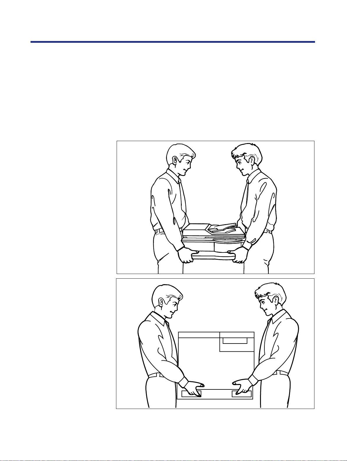
Moving the units
• Do not look directly at the light source lamps of the scanner when
scanning as this may be harmful to your eyes.
The scanner weighs approximately 22.5 kg {49.5 lbs.} and the printer
weighs approximately 49.5 kg {108.9 lbs.}. They must be handled by two
people. Turn the power off and remove the power cords when handling the
units.
16
Page 17
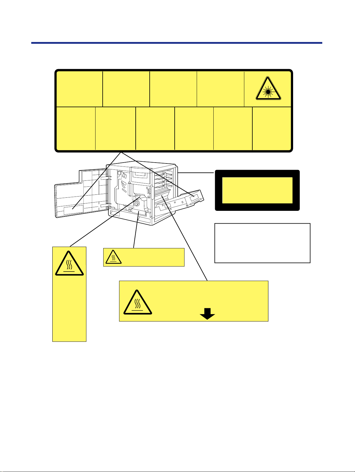
Caution labels
For Y our Safety
DANGER:
Invisible laser radiation
when open and interlock
defeated.
AVOID DIRECT
EXPOSURE TO BEAM.
PELIGRO:
Cuando se abre y se
invalida el bloqueo, se
producen radiaciones
invisibles de láser.
EVÍTESE LA
EXPOSICIÓN
A TALES RAYOS.
CAUTION:
Invisible laser radiation
when open and
interlocks defeated.
AVOID EXPOSURE
TO BEAM.
VARNING:
Osynlig laserstrålning när denna
del är öppnad och
spärrar är
urkopplade.
STRÅLEN
ÄR FARLIG.
VORSICHT:
Unsichtbare Laserstrahlung,
wenn Abdeckung geöffnet
und Sicherheitsverriegelung
überbrückt.
NICHT DEM STRAHL
AUSSETZEN.
VARO!:
Näkymätöntä
avattaessa ja
suojalukitus
ohitettaessa olet
alttiina lasersäteilylle.
ÄLÄ KATSO
SÄTEESEEN.
CAUTION:
HOT SURFACE INSIDE
ATTENTION:
Rayonnement laser invisible
dangereux en cas
d'ouverture et lorsque
la sécurité est neutralisée.
EXPOSITION DANGEREUSE
AU FAISCEAU.
VARNING:
Osynlig laserstrålning
när denna del är
öppnad och spärren är
urkopplad.
BETRAKTAEJ
STRÅLEN.
ADVARSEL:
Usynlig laserstråling
ved åbning når
sikkerhedsafbrydere
er ude af funktion.
UNDGÅ
UDSÆTTELSE FOR
STRÅLING.
ADVARSEL:
Usynlig laserstråling
når deksel åpnes og
sikkerhedslas brytes.
UNNGÅ
EKSPONERING
FOR STRÅLEN.
(220–240 VAC equipment)
CLASS
1 LASER PRODUCT
KLASSE
1 LASER PRODUKT
CLASSE
1 LASER PRODUIT
CLASE
1 LÁSER PRODUCTO
Laser diode properties
Laser output : 5 mW max
Wavelength : 780 nm
Emission duration : Continuous
CAUTION:
HOT SURFACE
INSIDE
ATTENTION:
SURFACE
CHAUDE
CI-INTERIEUR
VORSICHT:
HEISSE FLÄCHE
INTERN
ATENCION:
SUPERFICIE
CALIENTE
EN EL INTERNO
CAUTION:HOT SURFACE BELOW
ATTENTION:SURFACE CHAUDE CI-DESSOUS
VORSICHT:HEIßE OBERFLÄCHE DARUNTER
ATENCION:SUPERFICIE CALIENTE ABAJO
17
Page 18

For Y our Safety
FOR USERS IN U.K.
IMPORTANT:
FOR YOUR SAFETY PLEASE READ THE FOLLOWING TEXT CAREFULLY
Both the printer and scanner are supplied with a moulded three pin mains plug each for your safety and
convenience.
A 13 amp fuse is fitted in this plug. Should the fuse need to be replaced please ensure that the
replacement fuse has a rating of 13 amps and that it is approved by ASTA or BSI to BS 1362.
Check for the ASTA mark or the BSI mark on the body of the fuse.
If the plug contains a removable fuse cover you must ensure that it is refitted when the fuse is replaced.
If you lose the fuse cover the plug must not be used until a replacement cover is obtained. A
replacement fuse cover can be purchased from your local Panasonic Dealer.
IF THE FITTED MOULDED PLUG IS UNSUITABLE FOR THE SOCKET OUTLET IN YOUR HOME
THEN THE FUSE SHOULD BE REMOVED AND THE PLUG CUT OFF AND DISPOSED OF SAFELY.
THERE IS A DANGER OF SEVERE ELECTRICAL SHOCK IF THE CUT OFF PLUG IS INSERTED
INTO ANY 13 AMP SOCKET.
If a new plug is to be fitted please observe the wiring code as shown below.
If in any doubt please consult a qualified electrician.
WARNING: THIS APPLIANCE MUST BE EARTHED.
IMPORTANT: The wires in this mains lead are coloured in accordance with the following code.
Green-and-Yellow: Earth Blue: Neutral Brown: Live
As the colours of the wire in the mains lead of this appliance may not correspond with the coloured
markings identifying the terminals in your plug, proceed as follows.
The wire which is coloured GREEN-AND-YELLOW must be connected to the terminal in the plug which
is marked with the letter E or by the Earth symbol or coloured GREEN or GREEN-ANDYELLOW.
The wire which is coloured BLUE must be connected to the terminal in the plug which is marked with the
letter N or coloured BLACK.
The wire which is coloured BROWN must be connected to the terminal in the plug which is marked with
the letter L or coloured RED.
ASA
How to replace the fuse: Open the fuse compartment with a screwdriver and replace the fuse.
SCREWDRIVER
LN
FUSE
FUSE COVER
FOR USERS IN AUSTRALIA
This mark shows that the product complies with AS/NZS 3548.
N52
18
Page 19
Chapter 1
Cautions
Before You Start
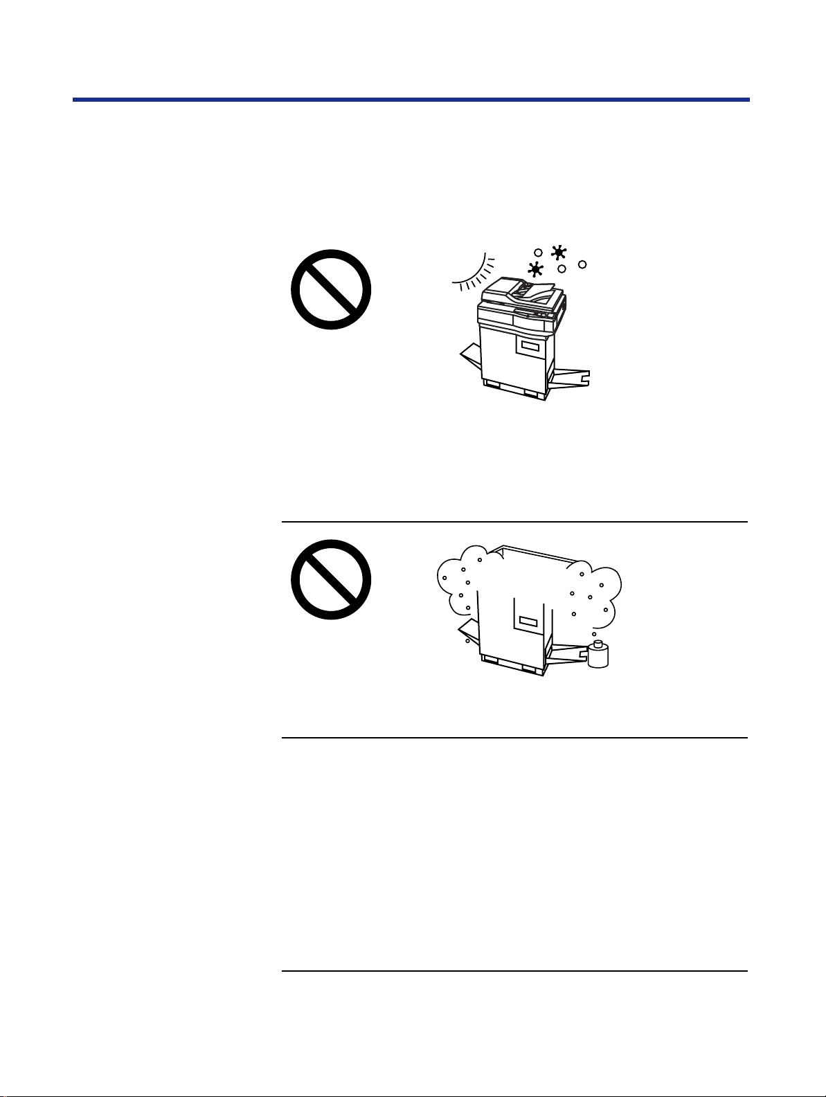
Before you set up your new system, please read the following information.
To avoid problems, do not use the equipment under the follo wing conditions:
• Direct exposure to sunlight
• Extremely high or low temperature [temperature range: 10˚C to 32.5˚C
(50˚F to 90.5˚F)]
• Extremely high or low humidity (humidity range: 20% to 80% RH)
• Condensation due to rapid change of temperature
• Areas of poor ventilation
• Areas of high dust or chemical fume concentration (solvent etc.)
• Unstable or unlevel surfaces
19
Page 20
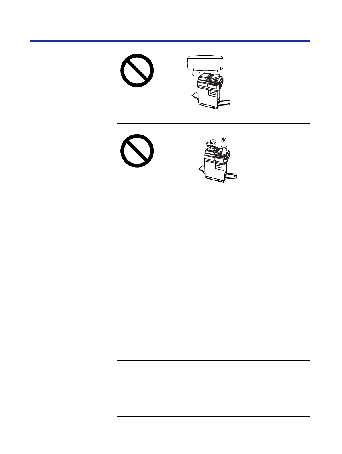
Before Y ou Start
• Directly in front of air conditioning vents
• Liquids near the equipment
• Liquid spills can cause severe damage.
20
• Too much media/document which exceeds the limit mark ( ) on the
guide of the tray.
• Front/right/left doors opened while the printer is operating; it may cause a
media jam.
• Any toner other than genuine Panasonic toner. It may damage the printer.
Page 21

Before Y ou Start
CD-ROM
To prevent accidental damage to the CD-ROMs:
• Do not touch or write on the surface of the disc.
• Do not leave the disc out of the protective case.
• Do not leave the disc in direct sunlight or near heat sources.
• Do not place heavy objects on the disc case or drop the case.
• To clean the disc, hold the disc by its edges and wipe it from the center to
the edges with a dry, soft cloth.
21
Page 22

Before Y ou Start
Static electricity damage
Interface cable
Waste disposal method
To prevent static electricity damage to any of the following components,
touch a grounded metal surface, such as the printer’ s bare metal frame prior
to touching the component.
•
The interface connectors—SCSI, parallel, and optional network
ADF interface connector
•
•
Electrical components, connectors inside the printer, any components on
the optional board (hard disk drive, SDRAM DIMMs, Ethernet network
card, or Token Ring network card)
The connector pins on the optional 2nd cassette feeder for the printer
•
Always use a shielded cable. Use of an unshielded cable can result in r adio
interference with data.
Waste material may be dumped or incinerated under conditions which meet
national and local environmental regulations.
22
Page 23

Features
Before Y ou Start
The KX-PS8100 system is a high quality system that provides fast color
image processing functions, including color scanning, color printing, and
color duplicating.
The KX-PS8100 system is comprised of two components:
• Color laser printer (KX-PS8101)
• Color scanner (KX-PS8102)
The KX-PS8100 system offers you the following functions:
• Scanning
• Printing
• Digital Duplicating (using Digital Duplicator Utility or the scanner panel)
These functions are available depending on the system.
Windows Macintosh
Scanner function
Scanning Yes Yes
Printing Yes
Digital Duplicating Yes
*1Only when using Network port.
*2
Digital duplicating using Digital Duplicator Utility is not available.
NOTES:
Yes*
Yes*
• Positioning the scanner on top of the printer will conserve space.
• Each component can be used individually.
• Additional SDRAM DIMM upgrades improve performance.
■ High quality
•
Resolution—Optical 600 dpi (dots per inch)
Flatbed: 30 to 9600 dpi is software selectable.
ADF: 60 to 2400 dpi is software selectable.
• Color
Full-color mode: Maximum 16.7 million colors
1
2
Monochrome mode: Maximum 256 grayscale levels
23
Page 24

Before Y ou Start
■ Image modification function
Image modification functions, such as density (gamma) adjustment, color
adjustment, and sharpening can be used to modify an image so that it
meets your requirements.
■ High speed
•
When scanning an A4 size document:
An A4 size document can be scanned in 7.8 seconds at 300 dpi, and 15.7
seconds at 600 dpi. (Initial time is not included. Actual time depends on
SCSI interface and host computer.)
■ Easy operation
•
Scanner driver—Easily scans full-color documents using a TWAIN
compliant application. (Windows and Macintosh)
• In addition to the TWAIN scanner driver, the Photoshop Plug-in scanner
driver is available using a Photoshop Plug-in compliant application.
(Macintosh)
Printer function
For additional information on scanner specifications, see page 284.
■ High quality
•
Resolution—Maximum 1200 dpi *
*1
A minimum of 48 MB of SDRAM DIMM is required.
1
■ High speed
•
Continuous printing on letter or A4 size paper
Full-color mode: Maximum 3.5 ppm (pages per minute) for 4 Color
(CMYK)
Maximum 4.7 ppm for 3 Color (CMY)*
Monochrome mode: Maximum 14 ppm
*2 only when using plain paper
2
■ Easy operation
•
Printer driver—Easily prints full-color documents.
24
Page 25

Before Y ou Start
■ Networking and client capabilities
•
Supports AppleTalk (EtherTalk), TCP/IP, and IPX (Novell) protocols
simultaneously by installing optional Ethernet Card
• Supports thicknet, twisted pair, and thinnet (via transceiver) cabling
• Ethernet support by installing optional Ethernet Card
• Token Ring support by installing optional Token Ring Card
• SMB (Microsoft®)
• IEEE 1284 compliant, Mini-Centronics type-C parallel connection based
on the IEEE P1284-C standard
NOTE:
• An ECP compatible parallel port is recommended for Windows® 95*
turn on the ECP mode, use the computer’s BIOS setup. Refer to the
computer’s documentation for details.
*1Microsoft® Windows® 95 operating system (hereafter Windows 95)
1
. To
■ Color capabilities
ColorWise™ CRDs (color rendering dictionaries) take full advantage of the
colors available on your printer. PostScript 3 RGB files are converted to the
printer’s CMYK color space during processing—optimizing them for
rendering and printing. CRDs available with the PostScript driver include:
• Photographic
• Presentation
• Transparency
Using the PostScript driver an image’s RGB data can be also converted to
the color space and gamut of the printer using RGB source profiles. Profiles
available include:
• EFIRGB
• sRGB (PC)
• Apple Standard
In addition, CMYK simulation settings can be used to simulate popular
offset printing press standards. Simulation settings include:
• SWOP
• Euroscale
• DIC
25
Page 26

Before Y ou Start
■ Color management
ColorWise VisualCal™ allows experienced users to calibrate the printer for
excellent color output—eliminating out-of-calibration color most printers
experience over time.
ColorWise Color Adjustment provides controls for globally modifying toner
density and brightness.
ColorWise Business Color specifies the application of toner using a
diffusion dither pattern, which is ideal for color fills and blends commonly
found in charts and graphs used in business applications.
■ Fiery WebTools
Fiery WebTools are utilities that enable users to manage the printer from the
Internet or your company’s intranet:
• Fiery WebDownloader
• Status
• Fiery WebSetup
• Fiery WebLink
• Fiery WebSpooler
Digital duplicator function
For additional information on printer specifications, see page 286.
■ High quality
•
Resolution—Resolution is set according to the selected mode.
Standard mode: 600 x 300 dpi (300 x 300 dpi for B/W Text)
Fine mode: 600 x 1200 dpi
■ Image conversion function
Adjusts individual toner densities.
Scanned colors R (red), G (green), B (blue) are converted to printed colors
C (cyan), M (magenta), Y (yellow), K (black) automatically.
26
Page 27

Before Y ou Start
■ High speed
•
Continuous full-color printing on letter size paper using ADF
(Automatic Document Feeder)
4 Color (CMYK)*
Standard mode Maximum 3.5 ppm
(pages per minute)
Fine mode Maximum 1.8 ppm Maximum 2.4 ppm
*1 “Text and Graphics” when using the scanner panel
*2 only when using plain paper
*3 “Photo” when using the scanner panel
1
3 Color (CMY)*2*
Maximum 4.7 ppm
3
■ Easy operation
•
Front Key Panel—Easily duplicate documents.
■ Digital duplicator utility
Includes various editing operations, such as color adjustment,
enlargement/reduction, drawing text strings, saving the layout image,
mirroring, and area duplicate.
For additional information on digital duplicator specifications, see page 288.
The icons in this document indicate:
:
Features and functionality which require an optional hard disk drive.
See “Installing a hard disk drive” on page 275.
: Features and functionality which require a minimum of 32 MB of SDRAM.
32
See “Installing additional memory” on page 278.
: Features and functionality available to printers operating in a networked environment.
See “Installing network cards” on page 281
27
Page 28

Before Y ou Start
System requirements
You can use the KX-PS8100 system in a networked environment and print
from a PC compatible computer running Windows or from a Macintosh
computer.
To operate the KX-PS8100 system effectively, see the following.
With a Windows computer
CPU: An IBM PC or compatible computer with P entium or
higher (133 MHz or faster CPU is recommended.)
Operating system*1: Windows® 3.1*2, Windows 95, Windows® 98*3
or Windows NT® 4.0*4 *5 (Intel only)
RAM: 16 MB or more
(More than 32 MB is recommended.)
Free disk space: 100 MB or more
Virtual memory: 16 MB or more (More than 32 MB is
recommended.) for Windows 3.1 or Windows 95
50 MB or more*
recommended.) for Windows NT 4.0
Display: Video card that can display more than 800 x 600 dpi
256 colors
(A video card that can display more than 32,000
colors is recommended.)
Drive: CD-ROM drive
Mouse: A mouse that is supported by Windows
6
(More than 100 MB is
28
*1 See page 289 to confirm which software is applied to your operating
system
*2 Microsoft® Windows® operating system Version 3.1 (hereafter Windows
3.1)
*3 Microsoft® Windows® 98 operating system (hereafter Windows 98)
*4 Microsoft® Windows NT® Workstation operating system, and Microsoft®
Windows NT® Server network operating system Version 4.0 (hereafter
Windows NT 4.0)
*5 Service Pack 3 or later version is required.
*6 In the Virtual Memory window, change this setting in the Initial Size box.
Page 29

Before Y ou Start
Interface: SCSI interface requirements
SCSI cable:
SCSI-2 (FAST SCSI) compatible (page 298)
SCSI-2 board:
ASPI Manager compatible SCSI-2 board
(Adaptec AHA-2940 is recommended.)
ASPI manager:
ASPI Manager is required.
(See the SCSI-2 board manual.)
Parallel interface requirements
ECP mode:
Based on the IEEE P1284-C standard
(An ECP compatible parallel port is
recommended for Windows 95.)
To turn on the ECP mode, use the computer’s
BIOS setup. Refer to the computer’s
documentation for details.
Cable: Appropriate interface cables for your network or
printer connection
With a Macintosh computer
To operate the KX-PS8100 system effectively, see the following.
CPU: More than PowerPC
(faster CPU is recommended.)
Operating system: Apple system software version 7.5.x, 7.6.x or 8.0
(Printer Driver)
Apple system software version 7.5.x, 7.6.x, 8.0, 8.1
or 8.5 (Scanner Driver)
Interface: Ethernet Card (Printing):
The KX-PS8100 Ethernet card does not enable
printing directly from the Macintosh computer.
Printing from a Macintosh can only be performed
if the KX-PS8100 and Macintosh are connected
to a network.
SCSI cable (Scanning):
SCSI-2 (FAST SCSI) compatible (page 298)
Cable: Appropriate interface cables for your network or
printer connection
To use ColorSync Color Matching of the scanner driver, ColorSync Manager
Version 2.0 or later is required.
Photoshop Plug-in is supported on Adobe Photoshop 3.0 or later.
29
Page 30
Before Y ou Start
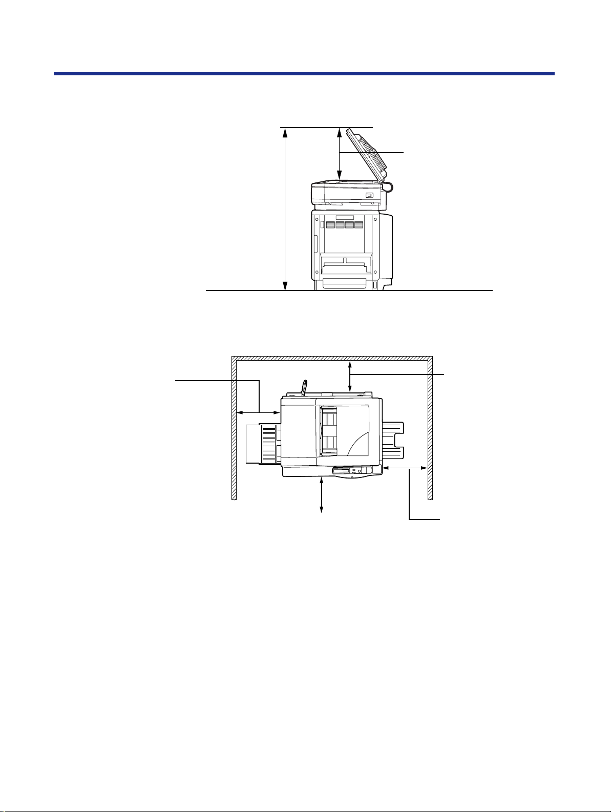
Minimum space requirements
111 cm (43.7")*
* 132.5 cm (52.2") with optional 2nd cassette feeder
50 cm (19.7")
ADF opening space
Rear
45 cm (17.7")
Multi-purpose tray
opening space
Power source
35 cm (13.8")
Controller board
opening space
Left
60 cm (23.6")
Front cover opening space
Right
50 cm (19.7")
Media tray opening
space
• The voltage lev el of the power source m ust not vary more than ±10% from
the voltage level marked on the nameplate (located on the back of the
units).
• Do not use an extension cord.
• Do not use a line conditioner, transient suppressor or surge protector as it
may cause a machine error.
30
Page 31

Unpacking
Before Y ou Start
Make sure that all of the items shown below were provided and have not
been damaged. Report damage or shortages to the reseller from which the
units were purchased. Page 2 includes an area for recording important
information such as the name of reseller, serial numbers, and date of
purchase.
NOTE:
• Save the original cartons and packing materials for future shipping and
transporting of the units. They have been specifically designed to protect
the equipment during shipment.
Scanner box
1. Scanner
2. ADF (Automatic Document Feeder)
3. Power cord
1
2
3
31
Page 32

1.
2.
3.
4.
5.
6.
7.
8.
9.
Before Y ou Start
Printer box
Printer (color imaging unit, fuser unit and media tray are included.)
Toner cartridges (black, cyan, magenta, and yellow)
Power cord
SCSI cable (for connection between the scanner and the printer)
Guide pins (2)
KX-PS8100 CD-ROM Disc1
(includes Printer driver & Utility)
KX-PS8100 CD-ROM Disc2
(includes Scanner driver & Utility, Operating Manuals and Acrobat
Reader)
CorelDRAW Select Edition (CD-ROM Disc1, 2)
Color Calibration Card
10. Setup Manual (The manuals in other languages may also be included.)
11. ID maintenance administrator password (sheet)
1
2 3
32
4
8
11
5
9
6
10
7
Page 33

Part names
Before Y ou Start
■ Front side view
■ Rear side view
33
Page 34

■
■
Before Y ou Start
Printer
Front side view
Front door (See page 40.)
Rear side view
SCSI connector
(See pages 61 and 65.)
Printer panel (See pages 38 and 197.)
Right side door
(See pages 43, 232 and
269.)
Output tray
(See page 41.)
Media tray
(See page 49.)
Fuser (See pages 215 and 226.)
Color imaging unit (See pages 40 and 214.)
Slot cover for optional network card (See page 282.)
[Network card*1 (See page 70)]
1
*
Some of the KX-PS8100 models have an
Ethernet card already installed.
SCSI ID NO. and terminator switches
(See page 66.)
34
Power switch
(See page 68.)
AC inlet
(See pages 62-64.)
Parallel interface
connector
(See page 64.)
Multi-purpose tray (MPT)
(See page 52.)
Left side door
(See page 52.)
[Media thickness switch*2
(See page 52.)]
*2Accessible by opening the
left side door
Page 35

Scanner panel overview
This section describes the functions of the scanner panel, illustrated below:
Before Y ou Start
LCD (Liquid Crystal Display) panel
Activity light
The scanner LCD has two 20-character lines to display the scanner’s or
duplicator’s status/error messages or the duplicator’s menu settings. When
the duplicator is ready, “Ready” with duplicate settings such as number of
copy, density setting is displayed.
INCREASE/NEXT
MODE
READY/ERROR
RESET
STOP
START
B/W
ENTER
START
COLOR
The activity light indicates the status of the scanner. It has the following
meanings:
This light Indicates
READY/ERROR indicator—
• The READY indicator (green)
READY/ERROR
ON: the scanner is ready for operation.
Blinking: the scanner is initializing or scanning.
• The ERROR indicator (orange)
ON: an internal error (Call for Service Error) has
occurred.
Blinking: user correctable error such as ADF jam has
occurred.
Status
Diagnosing…/Initializing…
READY Indicator
(green)
Blinking*
1
ERROR Indicator
OFF
Ready ON OFF
Scanning
Scanning (for duplicate)
Printing (for duplicate)
Blinking*
Blinking*
Blinking*
2
3
1
OFF
OFF
OFF
User Correctable Error OFF Blinking
Call for Service Error OFF ON
*1 Blinking with an interval of approximately 1.7 seconds
*2 Blinking with an interval of approximately 0.9 second
*3 Blinking with an interval of approximately 0.7 second
(orange)
35
Page 36

Before Y ou Start
Buttons
The scanner panel’s buttons have the following meanings:
This button Indicates
INCREASE/NEXT button—
•When the scanner is ready, pressing this button
increases the number of duplicates by 1. You
can set the number of duplicates from 1 to 99.
Pressing this button for more than 2 seconds
automatically increases the number of
INCREASE/NEXT
duplicates by 1.
Pressing this button for more than 8 seconds
increases the number of duplicates by 10.
•When the scanner is ready, pressing MODE +
INCREASE/NEXT decreases the number of
duplicates by 1. You can set the number of
duplicates from 1 to 99.
Pressing MODE + INCREASE/NEXT for more
than 2 seconds automatically decreases the
number of duplicates by 1.
Pressing MODE + INCREASE/NEXT for more
than 8 seconds automatically decreases the
number of duplicates by 10.
•In the Menu mode, pressing this button displays
the next selection.
MODE
MODE button—
•When the scanner is ready, pressing this button
enters the Menu mode.
•In the Menu mode, pressing this button displays
the next menu.
•Pressing MODE + START COLOR, or MODE +
START B/W allows you to select a print type
and starts the duplicating process.
•Pressing MODE + INCREASE/NEXT allows you
to decrease the number of duplicates.
(Continued)
36
Page 37

Before Y ou Start
This button Indicates
STOP/RESET button—
Pressing this button:
• Exits the Menu mode.
• Stops the duplicating process.
STOP
START
B/W
(Howev er, it does not stop immediately because
of data processing.)
• (When the number of duplicates is not 1)
Sets the number of duplicates as 1.
• (When the number of duplicates is 1)
Resets the scanner panel settings to the Menu
Default setting (when “Ready” is displayed).
• (When error messages such as “Memory
Overflow” is displayed)
Recover from an error situation.
START B/W button—
• When a document is placed in the ADF tray or
on the scanner glass, pressing this button
makes a black and white duplicate, regardless
of the color of the document.
START
COLOR
START COLOR/ENTER button—
• When the scanner is ready and a document is
placed in the ADF tray or on the scanner glass,
pressing this button makes a duplicate of the
document. If the original is a color document, a
color duplicate is created.
• In the Menu mode, after changing a selection,
pressing this button activates a selection. A “*”
appears to the left of the selection.
37
Page 38

Before Y ou Start
Printer panel overview
This section describes the functions of the printer panel, illustrated below:
LCD (Liquid Crystal Display) panel
Activity lights
The printer LCD has two 24-character lines to display the printer’s status/
error messages or menu settings.
READY
MENU
/EXIT
CANCEL
ENTER
CONTINUE
ERROR
The activity lights indicate the status of the printer. They have the following
meanings:
This light Indicates
READY indicator (green)—
•ON: the printer is ready for operation.
READY
•Blinking: the printer is warming up or in the Menu
mode.
•Blinking fast: the printer is printing.
38
ERROR
ERROR indicator (orange)—
•ON: an internal error ("Call for Service" error) has
occurred.
•Blinking: user correctable error, such as media
jam, open door, or a missing replaceable
component (e.g. Toner) has occurred.
Page 39

Before Y ou Start
Buttons
The printer panel’s buttons have the following meanings:
This button Indicates
MENU/EXIT button—
MENU
/EXIT
• When the printer is ready, pressing this
button enters the Menu mode.
• Pressing this button exits the Menu mode.
▼
/CANCEL button—
• Pressing this button cancels the data in
the printer.
• When the printer is in the Menu mode,
CANCEL
pressing this button:
—Displays the previous menu, item or
selection.
—Decreases the current numerical value of
the selection.
—Moves the cursor to left.
▲/CONTINUE button—
• When the printer is in the Menu mode,
pressing this button:
—Displays the next men u, item or selection.
CONTINUE
—Increases the current numerical value of
the selection.
• When the Semi Automatic Duple x option is
selected in the printer driver, press this
button to print on the opposite side of
page. (See the
Reference Guide
Utilities and Drivers
.)
ENTER
ENTER button—
This button is effectiv e only when the printer
is in the Menu mode. Pressing this button:
—Enters a sub - menu.
—Activates a selection.
39
Page 40

Chapter 2
Setup
This chapter describes setting up the KX-PS8100 system, connecting it to a
computer, and powering on the printer.
Setting up the printer
The general steps for setting up the printer are:
• “Preparing the color imaging unit” on page 40
• “Setting up the output tray” on page 41
• “Installing the toner cartridges” on page 42
reparing the color
imaging unit
After you have unpacked the printer and located it on a flat, stable surface,
you need to set it up.
To prepare the color imaging unit:
1
Open the printer’s front door.
40
Page 41

Setup
Setting up the output tray
2
3
Make sure that you have enough room for the output tray and that it is easy
to access.
Turn the upper green lever clockwise until it stops and
the arrows are aligned.
This tightens the internal belts to ready the unit for printing.
Close the printer’s front door.
To set up the output tray:
1
Remove the adhesive tape that holds the output tray
against the printer.
41
Page 42

Setup
Installing the toner cartridges
2
The toner cartridges that are shipped with the printer are starter cartridges.
They are installed in exactly the same manner as the optional cartridges;
the only difference is that the starter cartridges have less toner. The page
life expectancy is 3,000 pages, based on a 5% image area.
NOTE:
• Save all packing material for shipping purposes.
Lower the tray to the operating position.
To install the starter cartridges:
1
2
Remove the packaging from the each toner cartridge.
Remove the shipping cover from the each toner
cartridge.
CAUTION:
• To avoid possible toner spillage, do not tilt cartridge.
42
Page 43

Setup
3
4
Open the right side door.
CAUTION:
• Do not leave the right side door open for more than 1 minute; the
color imaging unit will be exposed to light and could be damaged.
Insert the each toner cartridge in the appropriately
labeled slot.
From top to bottom, the order of the toner cartridges is BLACK,
CYAN, MAGENTA, and YELLOW.
43
Page 44

Setup
5
Setting up the scanner
The general steps for setting up the scanner are:
• “Unlocking the scanner” on page 44
• “Installing the scanner on the printer” on page 45
• “Installing the Automatic Document Feeder” on page 47
When you have installed all the toner cartridges, close
the right side door.
Unlocking the scanner
44
The scanner must be unlocked before it can be used. The scanner lock is
located on the left of the scanner.
To unlock the scanner:
1
Turn the scanner lock counterclockwise with a flat-blade
screwdriver until the lock pops out.
......
......
......
......
Page 45

Setup
Installing the scanner on the printer
■ Before you begin
The scanner can be installed using two methods:
Method A. On top of the printer
Method B. On left or right side of the printer
AB
For Method A, see “Installing the scanner on the printer” on page 45 and
see “Installing the Automatic Document Feeder” on page 47.
For Method B, see “Installing the Automatic Document Feeder” on
page 47.
To install the scanner on the printer:
1
Remove the two top hole covers with a small flat-blade
screwdriver, then remove the two screws from the
printer.
45
Page 46

Setup
2
3
Install the guide pins and tighten them with a flat-blade
screwdriver.
Match the guide pins to the holes under the scanner,
and place the scanner gently onto the printer.
SAFETY CAUTIONS:
• The scanner without ADF weighs approximately 18.5 kg {38.1 lbs.}.
It must be handled by two people.
• When you place the scanner onto the printer, move the scanner holding
its handle to avoid injury.
46
Page 47

Setup
Installing the Automatic Document Feeder
4
To install the ADF (Automatic Document Feeder):
1
Lock the scanner by sliding it toward the right.
Hold the ADF vertically, then insert the tabs into the
holes on the rear of the scanner.
2
ADF
Close the ADF.
Tabs
47
Page 48

Setup
Loading media
3
The printer is shipped with one media tray (either Letter Paper or A4 Paper)
installed, however the printer supports five different trays as shown in the
following table.
Plug the end of the ADF cable into the ADF connector
located on the back of the scanner.
ADF cable
ADF connector
Tray Size
A4 Paper 210 mm x 297 mm (8.3" x 11.7")
A4 Transparency 210 mm x 297 mm (8.3" x 11.7")
Letter Paper 216 mm x 279 mm (8.5" x 11")
Letter Transparency 216 mm x 279 mm (8.5" x 11")
Legal Paper 216 mm x 356 mm (8.5" x 14")
NOTES:
• Make sure that you load the correct media. Each tray is designed and
labeled for only paper or transparency. If you load the incorrect media
type in a tray, it may cause a jam.
• If you have the 2nd cassette feeder (option) installed and you wish to use
the automatic cassette-switching feature (for a large print job, for
example), make sure that all trays in the printer are the same media type
and size.
• The transparency tray should only be inserted in the upper or middle tray
slots.
• Do not use a ink jet transparency that may be wrapped around the
fuser roller and cause damage.
48
Page 49

Setup
• The recommended transparency is 3M CG3710.
The transparency has a side to be printed. The other side has a leading
tape.
When loading the transparency, load it with the taped end entering the
printer first.
The transparency can be loaded in the multi-purpose tray and
transparency tray (option). To get better print result, use the transparency
tray. Note that the side to face up differs depending on each tray.
To load paper or transparencies:
1
2
3
Pull the media tray out of the printer.
To use an appropriate media tray, always check the label indication
on the tray.
Label
Remove all packaging materials from inside the media
tray; refer to the instruction sheet attached to the tray.
Push down on the metal plate until it clicks, locking it in
place.
49
Page 50

Setup
4
Fan the media (paper or tr ansparencies), and then tap it
on a level surface to avoid media jams or skewed
printing.
Do not fan the transparency to avoid fingerprints.
NOTES:
• To optimize your printer’s performance, always use clean,
unused media.
• Be careful not to leave fingerprints on the media, which can result
in a smudged print.
• Reusing media that has been fed through the printer once (for
example, after jams) can reduce the life of the consumables and
paper path components.
5
Place the media in the tray under the hooks.
The height of media should not exceed the limit mark on the tray, or
it may cause a jam.
When loading the
load it with the leading tape side facing up and the taped end
under the hooks. (See the illustration below.)
Taped side facing up
NOTES:
recommended transparency (3M CG3710)
Hook
Limit mark
• Load media with the print side down. Most media has instructions
recommending the side to be printed first.
,
50
• Do not mix different types or thicknesses of media in the media
tray at one time; this may cause a jam.
• When using transparency, be sure to use the transparency tray.
Page 51

Setup
Margins and print area
6
7
When the image is printed on the media, the image (print area) is a bit
smaller than the media size. You may need to adjust the page margins in the
application software to match the print area.
The following table and illustrations show the page sizes, the largest print
areas, and the margins for the media sizes supported on this printer.
Slide the media tray completely into the slot.
When using transparency with leading tape:
Remove the tape after printing.
Margins
Media Page Size Print area
Top Bottom Sides
Letter 216 mm x 279 mm
(8.5
"
x 11")
A4 210 mm x 297 mm
(8.3
"
x 11.7")
Legal 216 mm x 356 mm
(8.5
"
x 14")
Letter
216 mm x 279 mm
(8.5" x 11")
270 mm (10.6")
208 mm
(8.2")
289 mm (11.4")
208 mm x 270 mm
(8.2" x 10.6")
201 mm x 289 mm
(7.9" x 11.4")
208 mm x 346 mm
(8.2" x 13.6")
A4
210 mm x 297 mm
(8.3" x 11.7")
201 mm
(7.9")
4.2 mm
(0.17")
3.4 mm
(0.13")
3.2 mm
(0.13")
216 mm x 356 mm
346 mm (13.6")
4.3 mm
(0.17")
3.9 mm
(0.15")
6.0 mm
(0.24")
Legal
(8.5" x 14")
208 mm
(8.2")
3.9 mm
(0.15")
4.3 mm
(0.17")
3.9 mm
(0.15")
51
Page 52

Setup
Loading media in the multi-purpose tray
The multi-purpose tray (MPT) serves as an additional tray for loading any
type of media that ranges in size from 91 mm x 254 mm to 216 mm x 356
mm (3.6" x 10" to 8.5" x 14"). Use it to load a single sheet or a stack of
media, depending on the media’s type and thickness.
Use the multi-purpose tray to accomplish the following:
Print on standard and special media
• Standard media
—Laser paper [75 to 165 g/m2 (20 to 44 lbs.)]
• Special media
—Labels
—Envelope (#10 or larger size) [Black Text only]
—Transparency (The print quality may not be stable. Use the media tray
for best reliability.)
—Coated paper
Two-sided printing (Duplex printing) on laser paper
You should not expect the same print quality and reliability that you get with
one-sided printing. For details, see “■ Two-sided printing (Duplex printing)”
on page 292.
To set media thickness switch:
Because the printer accommodates various media weights from the multipurpose tray, media thickness can be manually selected for the most
reliable paper-picking. Follow these steps:
1
a) Open the left side door.
b) Move the switch to the desired setting.
The green media thickness switch is located on the paper f eeder
and has three settings:
b
a
Thin
Middle
Thick
52
Page 53

Switch setting Media
Setup
Thin (Default)
Middle
Thick
2
To load paper, transparency:
NOTE:
• Reusing media that has been fed through the printer (for example, after
For detailed information on media, see “Media” on page 290.
Close the left side door.
jams) can reduce the life of the consumables and paper path
components.
Laser paper 75 to 90 g/m2 (20 to 24 lbs.)
Laser paper 91 to 123 g/m2 (25 to 32 lbs.)
Transparency, Label, Coated paper
Laser paper 124 to 165 g/m2 (33 to 44 lbs.)
Envelope
1
2
Set the media thickness switch (see page 52).
a) Open the multi-purpose tray.
b) Extend the media support by sliding it outward.
a
b
53
Page 54

Setup
3
4
Separate the media guides to the approximate width of
the media.
Fan the media, and then tap it on a le v el surface to a v oid
media jams or skewed printing.
Do not fan the transparency to avoid fingerprints.
54
5
Insert the media with the printing side up into the multipurpose tray.
The height of media should not exceed the limit mark on the left
guide, or it may cause a media jam.
When loading the recommended transparency (3M CG3710) in
the multi-purpose tray, loading it with the leading tape side facing
down and the taped end entering the printer first. (See the
illustration below.)
NOTE:
• Do not use a ink jet transparency that may be wrapped around
the fuser roller and cause damage.
Taped side facing down
Page 55

Setup
6
7
8
To load an envelope in the multi-purpose tray:
Do not insert more than one envelope at a time. Only black text can be
printed on envelopes. For more detailed information, see “■ Envelopes” on
page 294.
1
2
3
Adjust the media guides to the media size.
Use the printer driver to select the multi-purpose tray.
When using transparency with leading tape:
Remove the tape after printing. (See page 51.)
Set the media thickness switch (see page 52).
Adjust the media guides to the width of the envelope.
Insert the envelope with the short end entering the
printer first and the printing side facing up.
The edge where the stamp will be located enters the printer first.
4
NOTE:NOTE:
• When wrinkle occurs, try printing with the envelope flap tucked in
as shown below.
From your computer, use the printer driver to choose
Envelope from the Paper Size menu and Paper
Source menu.
55
Page 56

Setup
To load labels in the multi-purpose tray:
For detailed information on labels, see “■ Transparencies and labels” on
page 293.
1
2
3
4
NOTE:
• Avoid printing labels if the temperature is too high; doing so may damage
Set the media thickness switch (see page 52).
Adjust the media guides to the width of the label sheets.
Insert label sheets in the multi-purpose tray with the
printing side up and insert the top of the sheets first.
The height of labels should not exceed the limit mark on the guide.
Choose MPT Label as the paper source in the Paper
tab of the printer driver.
consumables.
56
Page 57

■
■
Setup
Connecting the system
The scanner, printer, and computer can be installed in different
configurations depending on the function(s) to be used or computer system
to be connected.
Digital Color Imaging System (DCIS) standard system
(See pages 60, 64 and 70.)
The printer must be connected to computer through the Parallel port (local
port) or Network port to print documents.
You cannot print documents using the SCSI connection.
Network port or local port of a Windows PC
Functions Windows Mac
Scanning Documents Yes Yes
Printing Documents
Duplicating Documents Yes
1
*
Only when using Parallel port (local Port) or Network port.
2
*
Only when using Network port.
3
*
Duplicating Documents using Digital Duplicator Utility is not available.
Duplicating Documents using scanner panel is available.
Yes*
1
Yes*
Yes*
2
3
Connecting the scanner to a computer
(See page 62.)
Function Windows Mac
Scanning Documents Yes Yes
57
Page 58

Setup
■ Connecting the printer to a local port of a Windows PC
(See page 64.)
Function Windows Mac
Printing Documents Yes No
■ DCIS stand alone system
(See page 65.)
58
Function Availability
Scanning Documents No
Printing Documents No
Duplicating Documents Yes
Page 59

■ Connecting the printer to a network port
(See page 70.)
Function Windows Mac
Printing Documents Yes Yes
Setup
59
Page 60

Setup
Digital Color Imaging System (DCIS) standard system
If a SCSI-2 board has been installed in your computer, be sure it is
compatible (see “SCSI interface” on page 298). If it is not installed, be sure
to install only a recommended SCSI-2 board (see page 29).
If you do not have a SCSI cable, you will need to purchase one from your
local computer store or dealer (see “SCSI interface” on page 298).
Recommendation for connecting DCIS:
• We recommend you to connect your DCIS with only one SCSI device.
• For a SCSI chain with up to three SCSI-2 (FAST SCSI) devices
connected, the total length of the SCSI cables must be less than 3 m
(9.8 ft.).
• Use shielded cables for SCSI-2 (FAST SCSI).
NOTE:
• Although a SCSI chain may exceed the recommended length and still
operate we cannot guarantee this operation.
1
Make sure the computer, scanner, printer and the other
connected peripheral devices are turned off.
2
Computer’s
SCSI connector
Connect the SCSI cable (not provided) to the
computer’s SCSI connector and to the scanner’s SCSI
connector A or B.
The SCSI-2 board must be installed in the computer.
If you do not have a SCSI-2 board or a SCSI cab le , y ou will need to
purchase one from your local computer store or dealer (see “SCSI
interface” on page 298).
SCSI connector
A or B
SCSI cable
60
Page 61

Setup
3
4
Connect the SCSI cable provided to the printer’s SCSI
connector and to the scanner’s SCSI connector.
The printer must be the last device in the chain because the printer
has only one SCSI connector.
Scanner’s SCSI
connector
SCSI
cable
Printer’s SCSI
connector
Make sure the SCSI ID No. of the scanner is 2 and that
of the printer is 1. (They are the default settings.)
5
If you have other devices connected to the computer, make sure
•
that each SCSI device has a different ID No.
To change an ID No., use ID No. switches (#1, #2, #3) located on
•
the back of the scanner or ID No. switches (#2, #3, #4) located on
the back of the printer. See Table 1 on page 66.
ON
1234
1234
ON
Scanner
Printer
Make sure the terminator switch (#4) of the scanner is
set to OFF and that switch (#1) of the printer is set to
ON. (They are the default settings.)
If you have other devices connected to the computer, make sure
•
the terminator switches of all those devices are set to OFF.
OFF
•
To change the terminator setting, use the terminator switch
located on the back of the units.
61
Page 62

Setup
Connecting the scanner to a computer
6
NOTE:
• The terminator must be installed or set to ON on the last SCSI device only
1
Connect the power cords to the scanner’s AC inlet, to
the printer’s AC inlet and to AC outlets.
AC inlet
Power cord
AC outlet
AC outlet
Power cord AC inlet
(see page 66).
Make sure the computer, scanner and the other
connected peripheral devices are turned off.
62
2
Connect the SCSI cable (not
SCSI connector and to the scanner’ s SCSI connector A or B .
• The SCSI-2 board must be installed in the computer.
If you do not have a SCSI-2 board or a SCSI interface cable, you
will need to purchase one from your local computer store or
dealer (see “SCSI interface” on page 298).
• If other SCSI devices are connected to the computer , connect the
scanner anywhere in the SCSI chain.
Computer’s SCSI
connector
provided
SCSI cable
) to the computer’ s
SCSI connector
A or B
Page 63

Setup
3
4a
4b
5
Make sure the SCSI ID No. of the scanner is 2 (default
setting).
•
If other devices are connected to the computer, make sure that
each SCSI device has a different ID No.
• To change the scanner’s ID No., use the ID No. switches (#1, #2,
#3) located on the back of the scanner. See Table 1 on page 66.
1234
ON
If the scanner is the last device, set its terminator switch
(#4) to ON. Go to step 5.
If the scanner is not the last device, make sure the
terminator switch (#4) is set to OFF (default setting).
Connect the power cord to the scanner’s AC inlet and to
an AC outlet.
AC outlet
AC inlet
Power cord
63
Page 64

■
Setup
Connecting the printer to a local port of a PC
CAUTION:
Always use a shielded interface cable. Use of an unshielded cable can
•
result in radio interference with data.
NOTE:
Printing through a serial port (LocalTalk) is not supported on Macintosh
•
computers.
Using a parallel interface cable
If you do not have a parallel interface cable, you will need to purchase one
from your local computer store or dealer (see “Bidirectional parallel
interface” on page 296).
1
2
Make sure the computer, printer and the other
connected peripheral devices are turned off.
Connect the Centronics Type C parallel interface cable
to the computer’s parallel connector and the printer’s
parallel interface connector.
Computer’s parallel
connector
NOTES:
•
The actual connector on the computer may differ depending on
the manufacturer of the computer.
•
If the cable is connected to the PC via a printer buffer or switch,
the printer may not print.
3
Connect the power cord to the printer’s AC inlet and to
an AC outlet.
Parallel interface
connector
Centronics Type C parallel cable
64
Power cord
AC outlet
Page 65

Setup
DCIS stand alone system
1
2
3
Make sure the scanner and printer are turned off.
Connect the SCSI cable provided to the scanner’s SCSI
connector A or B and to the printer’s SCSI connector.
Scanner’s SCSI
connector
SCSI cable
Printer’s SCSI
connector
Make sure the terminator switches (scanner:#4/
printer:#1) are set to ON.
ON
1234
1234
ON
Scanner
Printer
•
To change a terminator setting, see page 66.
4
5
NOTE:
• The Printer function is also available if the printer is connected to the
Connect the power cord to the scanner’s AC inlet and to
an AC outlet.
Connect the other power cord to the printer’s AC inlet
and to an AC outlet.
computer with a parallel interface cable.
OFF
65
Page 66

Setup
1234
ON
OFF
SCSI ID No.
switches
Terminator switch
Setting the SCSI ID number and terminator
■ Setting the SCSI ID number
In most cases, there is no need to change the default settings (see Tables 1
and 2 below).
However, if you have other peripheral devices connected in a SCSI chain,
check if their ID numbers conflict with that of the printer or scanner. Be sure
to choose an unassigned ID number.
SCSI ID number can be changed by using the scanner SCSI ID No.
switches (#1, #2, #3) [see Table 1 below] and/or printer SCSI ID No.
switches (#2, #3, #4) [see Table 2 below]. To set them, use a pointed object
like a pen (do not use pencil).
Table 1 (scanner)
SCSI ID
No.
0 OFF OFF OFF
1 ON OFF OFF
2 OFF ON OFF
3 ON ON OFF
SCSI ID No. switches
#1 #2 #3
SCSI ID No. switches
OFF
ON
1234
ON
Terminator switch
66
4 OFF OFF ON
5 ON OFF ON
6 OFF ON ON
7ONONON
: Default setting
Table 2 (printer)
SCSI ID
No.
0 OFF OFF OFF
1 ON OFF OFF
2 OFF ON OFF
3 ON ON OFF
4 OFF OFF ON
5 ON OFF ON
6 OFF ON ON
7ONONON
: Default setting
SCSI ID No. switches
#2 #3 #4
Example:
SCSI ID No.=2
Terminator=OFF
Example:
SCSI ID No.=1
Terminator=ON
Page 67

Setup
■ Setting the terminator
The default setting of the scanner is set to OFF and that of the printer is set
to ON.
The terminator setting can be changed by using the terminator switch
(scanner:#4, printer:#1). To set it, use a pointed object like a pen (do not
use a pencil).
Terminator ON:
Terminator OFF:
67
Page 68

Setup
Power on
1
2
Turn ON the scanner, then the printer.
The scanner will be ready after approximately 20
seconds, and “Ready”, “PTR Initializing” will be
displayed on the scanner LCD panel.
3
4
NOTES:
• When you power on your system for the first time, if “New Hardware
• If you use Macintosh 7500/7600/8500/9500, follow the procedure below.
a) The READY indicator on the printer starts flashing
and “Initializing” is displayed on the printer LCD
panel.
b) After approximately 3.5 minutes, the printer’ s READY
indicator is illuminated and “Ready” is displayed on
the printer LCD panel.
The printer is ready for printing.
Turn ON the computer after “Ready” is displayed on the
scanner and printer LCD panels.
Found” is displayed on the computer screen, see page 102.
KX-PS8100 does not operate properly in the procedure above.
1. Turn on Macintosh 7500/7600/8500/9500.
2. Turn on the scanner, then the printer.
3. Check “Ready” is displayed on the scanner and printer LCD panels.
68
Page 69

Setup
Installed Memory (RAM): 32MB
Disk: Not Installed
Memory
Panasonic KX-PS8100
Configuration
Printer Name: KX-PS8100
Resolution: 600 dpi x 600 dpi
Printer Language(s): PS3
Calibration: NO
Printing a Test Print from the printer panel
There are several pages that you can print from the printer panel. This
section provides instructions for printing a Test Print.
The Test Print includes a color sample as well as the printer’s name,
enabled network protocols, memory configurations, and installed options.
You can print a Test Print before you set up the KX-PS8100 system—or at
any other time from the “Ready” or the “Ready(Sleep)” screen.
To print a Test Print:
1
2
3
4
Turn on the printer and allow it to warm up.
Messages appear on the printer panel as the KX-PS8100 printer
runs through its power-up tests.
From the Ready screen, press the MENU/EXIT button
on the printer panel.
Press the ENTER button.
Press the ▲/CONTINUE button until you see Test Print
and then press the ENTER button.
5
For more information, see page 202 .
Examine the quality of the Test Print.
Test Print
69
Page 70

Ethernet network connections
Chapter 3
Connecting the Printer to a Network
This chapter describes how to connect your printer to a network. You can
connect the printer to your network with thicknet, twisted pair, or thinnet.
This chapter provides information about:
•
“Ethernet network connections” on page 70
“Token Ring network connections” on page 72
•
“Setting up TCP/IP printing” on page 73
•
TCP/IP stands for Transmission Control Protocol/Internet Protocol.
“Setting up IPX (Novell) printing” on page 82
•
IPX stands for Internet Packet Exchange.
•
“Setting up Windows 95 clients for SMB printing” on page 91
“Setting up Windows NT 4.0 clients for SMB printing” on page 93
•
SMB stands for Server Message Block.
After you have connected the printer to the network, follow the setup
instructions in Chapter 6 “Setup from the Printer Panel and WebSetup”.
Network connections
This section describes the types of network connections supported by the
KX-PS8100 system. Optional netw ork card is availab le from your P anasonic
dealer. For more information on upgrade options, see Chapter 10 “Options”.
IMPORTANT:
•
Use a shielded cable when using a RJ45 connector port or an AUI
connector port to ensure emission compliance to avoid radio frequency
interference.
•
Thinnet (thin coaxial cable or 10Base2)
Uses an external transceiver (media access unit, or MAU) to attach to the
AUI (attachment unit interface) connector on the printer.
•
Thicknet (thick coaxial cable or 10Base5)
Cable connects directly to the AUI connector on the printer.
•
Twisted pair (Category 5 shielded twisted pair cable or 100BaseTX)
Uses 8-pin RJ-45 connector that plugs into the RJ-45 jack on the printer.
NOTE:
•
Category 3, shielded twisted pair cable is supported on 10BaseT
networks.
70
Page 71

Connecting the Printer to a Network
AUI connector
RJ-45 jack
Parallel interf ace
connector
NOTE:
• Shut off the printer before connecting it to any network device. Only one
Ethernet connection should be made to the printer at a time.
To connect a thinnet cable to the printer:
1
2
3
4
To connect a thicknet cable to the printer:
1
2
Make sure the computer, printer and the other
connected peripheral devices are turned off.
Connect the MAU transceiver to the AUI connector on
the back of the printer. Secure the connection using the
slide latch on the AUI connector.
Connect the thinnet cable to the BNC connector on the
transceiver.
Turn on the printer and then the computer.
Make sure the computer, printer and the other
connected peripheral devices are turned off.
Connect the thicknet cable connector to the AUI
connector on the back of the printer.
3
Turn on the printer and then the computer.
71
Page 72

Token Ring network connections
Connecting the Printer to a Network
To connect a twisted pair cable to the printer:
1
2
3
For Ethernet speed setting, see “Network Port Setup” on page 146.
The printer supports the shielded twisted pair cable (Category 5 shielded
twisted pair cable) that plugs into the RJ-45 jack on the back of the printer.
Make sure the computer, printer and the other
connected peripheral devices are turned off.
Connect the RJ-45 cable to the RJ-45 jack on the back
of the printer.
Turn on the printer and then the computer.
RJ-45 jack
(Use shielded cable only.)
Parallel interf ace
connector
To connect the cable to RJ-45 jack on the printer:
1
2
3
For Token Ring settings, see “Network Port Setup” on page 146.
Make sure the computer, printer and the other
connected peripheral devices are turned off.
Connect the cable from the Token Ring MAU (Media
Attachment Unit) to RJ-45 jack on the back of the
printer.
NOTE:
•
A Media Attachment Unit (MAU) is a network hub for a Token
Ring Network.
Turn on the printer and then the computer.
72
Page 73

Setting up TCP/IP printing
Setting up the printing environment
TCP/IP provides network services for high-speed local and wide area
networks and heterogeneous environments including PC compatibles,
Macintosh computers, minicomputers, and mainframes running diverse
operating systems. The printer supports the lpr protocol for printing over
TCP/IP networks. Network users submit print jobs to a named printer.
Workstations on a TCP/IP network can print directly to the printer, or can
print to a Windows NT 4.0 server or UNIX workstation acting as a print
server.
Before you install the printer on a TCP/IP network, you need to obtain a
unique IP address. Contact your network administrator for this information.
To set up printing on a TCP/IP network, the network administrator must
follow these steps:
To set up IP Address/Subnet mask on the KX-PS8100:
Connecting the Printer to a Network
1
2
3
From the Ready screen, press the MENU/EXIT button
on the printer panel to access the printer setup menus.
Press the ▲/CONTINUE button until you see Network
Protocol Setup on the printer LCD panel. Press the
ENTER button to access the TCP/IP Setup menus.
In the next step you will enable TCP/IP network communication
according to your network type.
Press ENTER button to advance to the Enable TCP/IP?
screen. Press ENTER button and press ▲/CONTINUE
button to select Yes, and then press ENTER button
again to advance to the Ethernet IP Address screen.
Press ENTER button.
73
Page 74

▲
Connecting the Printer to a Network
4
5
6
7
Use the ▲ /CONTINUE button to select a number in a
valid, unique IP Address for the KX-PS8100. Press
⁄⁄
⁄⁄
/CANCEL button to accept a number and mov e to the
left—to the next number.
NOTE:
•
On the printer, numbers are entered from right to left. Press the
/CONTINUE button to scroll through numbers from 0 to 9.
Press the
next.
When you have finished entering all numbers in the
address, press ENTER button to advance to the Subnet
Mask screen. Press ENTER .
Use the ▲ /CONTINUE button to select a number as the
Subnet Mask value for the KX-PS8100. Press
⁄⁄
⁄⁄
/CANCEL button to accept a number and mov e to the
left—to the next number.
Specify the Gateway Address in the printer’s Setup
menus, if needed.
⁄
/CANCEL button to accept a number and mov e to the
8
See “Network Protocol Setup” on page 148 for details.
When you have finished entering all numbers, press
MENU/EXIT button.
After being rebooted, the printer will return to Ready mode.
74
Page 75

Connecting the Printer to a Network
UNIX server print queues
■ Setting up NIS server
If the site is using NIS (Network Information Services), a superuser must
add the printer name and IP address to the system’s database of network
printers.
1
2
3
Add the KX-PS8100 to the network’s IP host table.
This step must be performed on the master NIS (server) machine.
After adding the printer entry, the updated database must be
released to network users.
For the printer name, specify the print server protocol,
the print connection (queue), and the spool file.
Activate the printer connection.
Depending on your system, you may restart the printer daemon or
tell the printer to accept print requests.
■ Print queues
Print spooling is the process of sending print jobs to a defined location on a
hard disk, in this case the Print or Hold queues. Printers without a hard disk
drive can only receive print jobs over the Direct connection. Jobs sent to the
Direct connection are transferred from the computer to the printer’s
SDRAM.
NOTE:
• If the printer has a hard disk drive and 32 MB of memory installed, Direct,
32
Print, and Hold print connections are automatically available. If the printer
does not have a hard disk drive, only the Direct connection is available.
The lpr protocol is a printer spooling system. It is a set of programs that
accepts printing requests from many users on a network, routes them to the
proper print server (in this case, the KX-PS8100), and accepts requests to
display a queue’s status or to remove jobs from a queue.
The lpr system is included in the standard installation of Berkeley-based
UNIX systems, SunOS 4, and Solaris.
Use the examples that follow as a guide in helping you set up your network
for printing to the printer.
NOTE:
• In these examples, KX-PS8100 is used as the printer name (the IP
hostname), and KX-PS8100q is used to indicate the KX-PS8100 Print
queue.
75
Page 76

Connecting the Printer to a Network
Since the printer supports only one TCP/IP (lpr) connection at a time, you
can use the same name for the hostname and the queue name. However,
the examples indicate where you should make a distinction if you want to
use different names.
To add the printer as a network printer to all UNIX systems:
1
2
3
4
Log in to your UNIX host as the root user.
Edit your /etc/hosts file to include the printer as a
network device.
The following is a sample entry for the printer:
192.9.228.1<TAB>KX-PS8100<TAB>#comments
where <TAB> indicates that you press the tab key.
The IP address is followed by the official hostname, and these are
followed by aliases, if any. Type the entry exactly as shown, without
a space before the IP address.
NOTE:
• For sites that use DNS (Domain Name System) or that use NIS or
NIS+, consult the documentation or the network administrator for
instructions on publishing the printer entry.
Save and exit the hosts file.
Confirm the connection using the ping command.
See “Verifying the TCP/IP network connection” on page 79.
76
5
If your UNIX system uses SunOS 4 or another BSDbased variant, go to the next section.
If your system uses Solaris 2, follow the steps on page 78.
Page 77

Connecting the Printer to a Network
To set up printing on a UNIX system running SunOS 4 or another
BSD based variant:
1
2
On each workstation that will print to the printer, log in to
your UNIX host as the root user.
Create an entry for the printer in your /etc/printcap file.
The following is a sample printcap entry for the printer. Note that the
remote hostname you enter in the rm line must exactly match the
name you entered in the /etc/hosts file.
KX-PS8100q:\
:lp=:\
:rm=KX-PS8100:\
:rp=xjdirect:\
:lf=/var/spool/lpd/KX-PS8100q/log:\
:sd=/var/spool/lpd/KX-PS8100q:\
:mx#0:sf:sb
The spool directory KX-PS8100q
directory itself is created in step 3. Similarly, the log file is specified
here and created in step 4. The spool directory is write-protected
(from everyone but a daemon user and daemon group); users
cannot modify or remove files other than their own.
It is possible to set up to two additional printer entries, one with the
rp name xjprint and one with the name xjhold. The rp name
indicates the KX-PS8100 queue to which jobs are sent when you
print to the named printer.
A printer entry with the rp name xjhold routes all jobs to the
KX-PS8100 Hold queue. Therefore, to print those jobs, they must
be moved to the Print queue or deleted using Fiery WebSpooler.
is specified here, and the
3
NOTE:
• Use the rp name xjprint if your KX-PS8100 has a hard disk, or is
configured with more than 32 MB of memory. Printers without a
hard disk drive and 32 MB of memory can not use Print or Hold
queues (rp name: xjprint and xjhold), they can only receive print
jobs over the Direct connection.
Create a spool directory for the printer in the /var/spool
directory.
For example, enter the following:
mkdir -p /var/spool/lpd/KX-PS8100q
chown daemon /var/spool/lpd/KX-PS8100q
77
Page 78

Connecting the Printer to a Network
4
5
To set up printing on a UNIX system running Solaris 2:
1
2
3
Create the log files.
For example, enter the following:
cp /dev/null /var/spool/lpd/KX-PS8100q/log
Reboot the machine.
On each workstation that will print to the printer, log into
the UNIX system as the root user.
At the UNIX prompt, type lpsystem -t bsd KX-PS8100
This tells your system that the printer is a print server of bsd
(Berkeley Software Distribution) type.
Type lpadmin -p KX-PS8100q -s KX-PS8100\!xjdirect
This command creates an internal queue on the workstation and
points it to the printer. The general format of this command is:
4
5
lpadmin -p <queue name> -s <hostname>\!xjdirect
NOTE:
• The name xjdirect after the exclamation point is for configuring
the printer; it is an internal name that the printer requests. It must
be xjdirect; it is not a user-selectab le name . This is the only place
where it is entered.
As with SunOS 4 or other BSD based systems, when printing to
printers with a hard disk and a minimum of 32 MB of memory it is
possible to configure up to two additional printer entries, one with
the rp name xjprint and one with the rp name xjhold (see page 77).
Type accept KX-PS8100q
This command tells the printer to accept print requests from your
workstation. You are now ready to print from the workstation to the
printer.
Type enable KX-PS8100q
78
Page 79

Connecting the Printer to a Network
Verifying the TCP/IP network connection
Before a device on a TCP/IP network can send print jobs to the printer, the
printer must be given a valid IP address and subnet mask, as well as a
gateway address, if applicable. The printer is given these addresses in the
printer’s Network Protocol Setup. The IP address is used on all TCP/IP
networks and must always be assigned before the printer can be verified
across the network.
Because TCP/IP networks require some UNIX setup by the network
administrator, you may not be able to send a test page from the driver
across the network to the printer immediately after installation. The f ollowing
procedure enables you to verify that there is a proper connection between
the printer and the network without using the printer driver to print a test
page. Before you begin this procedure, verify that the printer is functioning
by printing a page from the printer panel.
For step by step instructions, see “Printing a Test Print from the printer
panel” on page 69.
Once the printer’s TCP/IP setup is complete, you can verify the availability
of the printer using the ping command from the DOS prompt with Windows
95, from the Command prompt with Windows NT 4.0 or from UNIX.
To verify the TCP/IP connection:
To see if the printer responds to its address, use the ping
command.
Use the format:
ping <IP address>
Use the printer IP address assigned in Network Protocol Setup. After the
printer has been given a hostname by your network administrator, you can
also ping the name you gave it:
ping <hostname>
The server should respond with a message such as:
<IP address> is alive.
Some systems will respond with a continuous display of output from the IP
address. To stop the output, press the (Control) + (C) keys.
79
Page 80

Connecting the Printer to a Network
Setting up TCP/
IP clients for
running
Fiery WebT ools
Setting up TCP/ IP clients for printing
If the printer is being added to an existing network, each TCP/IP client is
already running TCP/IP client software.
The KX-PS8100 printer supports TCP/IP client software on UNIX
workstations, PC compatibles, and Macintosh computers. With Macintosh
computers however, it is easiest to use the built-in AppleTalk protocol to
communicate directly with the printer.
If the client workstation is a PC running Windows, set up the printer as a
Windows PostScript printer by installing the PostScript printer driver, as
described in Chapter 4. For setting up your networking software, see the
documentation for your networking environment.
Fiery WebTools software comes pre-installed on the KX-PS8100 printer .
Fiery WebTools include: WebSpooler, Status, WebDownloader , W ebSetup
and WebLink.
When TCP/IP is enabled for the printer in Network Protocol Setup,
Fiery WebTools are immediately available to clients that:
• Are connected to a TCP/IP network with a consistent set of IP addresses,
one for the printer and one for each computer connect to the printer.
• Have a Java enabled Web browser.
The recommended browsers are:
• Netscape Navigator 3.04 for Macintosh computers,
• Microsoft Internet Explorer 4.0.1 SP1 or Netscape Communicator 4.0.4
for Windows computers.
NOTES:NOTES:NOTES:
• Microsoft Internet Explorer 3.x does not support the WebDownloader.
• WebDownloader is not supported on Macintosh computers.
Netscape and Microsoft continue to release frequent updates to their
browsers. As support cannot be guaranteed for all versions, use the
versions specified above for best results.
To access Fiery WebTools, enter the IP address or DNS name of the printer
(KX-PS8101) as a URL in the Internet browser. For more information, see
page 154.
80
Page 81

Connecting the Printer to a Network
Printing and administering print jobs
Once the printer has been properly installed on the TCP/IP network, users
should be able to send print jobs to the KX-PS8100 from most applications.
UNIX clients also commonly use UNIX printing commands to print
PostScript files and text files to the printer.
For information on printing PostScript files and text files using UNIX
commands, see Part 3 of
If you have superuser privileges you can remove any lpd jobs from the
printer queue; removing your own jobs doesn’t require special privileges.
To remove jobs from the printer queue:
On a UNIX system running SunOS 4 or other BSD-based
variant, use the lprm command to remove jobs from the queue .
To remove job number 123 from the print queue of your KX-PS8100 named
printer, you would type:
lprm -P<printername> <job #…>
or, for example: lprm -PKX-PS8100 123
The lprm command reports the names of any files it removes.
To determine the job number, use the lpq command described below.
lpq -P<printername>
Utilities and Drivers Reference Guide
.
On a UNIX system running Solaris 2, use the cancel command
to remove jobs from the queue.
Type:
cancel <job ID>
For example, to remove a job whose ID is printer-123 from the print queue
of your KX-PS8100, type:
cancel printer-123
To find out a print job’s job ID, use the lpstat command described below:
On a UNIX system running Solaris 2, use the lpstat command
to see printer jobs in the queue.
lpstat -o <queue name>
For example, if your printer queue is named KX-PS8100q, type:
lpstat -o KX-PS8100q
The returned list of jobs includes each job ID.
Once lpr print jobs are spooled to the printer’s hard disk, you can use
WebSpooler to monitor print jobs.
81
Page 82

Connecting the Printer to a Network
Setting up IPX (Novell) printing
IPX, Novell’ s Internetwork P ack et Exchange protocol, runs on networks that
include a Novell NetWare server. The server, typically a dedicated PC, is
usually configured to control workstation access to shared resources. In
addition to other services, NetWare servers use IPX protocols to provide
spooling, queue management, and print services to computers (including
Macintosh, DOS, UNIX, and VAX) whose operating software is compatible
with IPX protocols.
This section describes network setup for an IPX (Novell) network.
Overview of IPX printing to the KX-PS8100
NetWare file servers support the creation of print queues, storage areas for
print jobs. When a user on a network workstation prints a job, the job is sent
to a print queue on the NetWare server. The job is spooled to the NetWare
file server disk, freeing up the workstation.
The queues on the NetWare server must be named to match the Direct
connection and Print queue on the printer. The NetWare queue names
should be given an extension corresponding to the KX-PS8100 printing
connection, as follows:
_print
_hold
_direct
NOTE:
• The NetWare queues names must be given the above all lowercase
English extension (_print, _hold or _direct), even if any language’s
NetWare server is used.
When the printer is configured to connect to a NetWare server, it polls the
NetWare server for jobs in each of its queues. If jobs are found, they are
transferred over the network to the matching connection: Print to Print,
Direct to Direct. While a job is processed and printed, a record of the job is
being created. You can access the Job Log containing these records at any
time.
82
When the printer is connected to a NetWare print queue that is defined on
the NetWare server, the printer polls the queue for jobs and receives them
over the network for immediate processing and printing. All printer jobs are
sent from the printer queue on the NetWare server to the printer.
NOTE:
• It is not recommended to connect printer directly to NetWare server via
LPT port. It may cause unexpected print result.
Page 83

Connecting the Printer to a Network
To set up network printing, enable IPX/SPX Setup from the printer panel
(see “Network Protocol Setup” on page 148), and set up the PServer using
WebSetup after configuring the NetWare server (see “■ PServer Setup tab”
on page 162).
Configuring the
NetWare server
This section explains how to set up the NetWare server so that networked
users can print to the printer from their workstations. There are two stages
to this setup:
• The network administrator must set up a print queue on the NetWare
server so users can print to it, and the printer can receive print jobs
from it.
• Optionally, the administrator can set up the server for network installation
of PostScript printer drivers on client workstations.
Before configuring a NetWare file server for printing to the KX-PS8100,
make sure that it is connected to a functioning IPX network. Then, log in as
the supervisor on a PC connected to the NetWare file server, and configure
the file server as described in the following sections.
Before you begin, you’ll need to determine the following names:
• The name of the NetWare file server on which you will define the printer
as a new print server.
• The name of the NetWare print server. This name is used for
communication between the printer and the NetWare file server.
• The name to assign to the KX-PS8100 Direct, Print or Hold queue. If you
are defining a Hold queue, the last five characters must be _hold. You
need to set up at least one print queue on the NetWare server for jobs
that will be printed by the printer. Users will see and print to the name you
assign to the Print queue.
Names should be as brief and descriptive as possible. Server names
cannot begin with a period and cannot include spaces or punctuation
characters other than periods.
• To complete network setup, you will need to log in to the NetWare file
server and the new print server from the printer. You will need a login
name and, if access to the server is restricted, a login password.
83
Page 84

Connecting the Printer to a Network
■ Setting the NetWare 4.x bindery context
Novell 4.x servers use a different environment setup than Novell 3.1x
servers. (If your server is using NetWare 3.x, proceed to “Setting up a
KX-PS8100 print queue” on page 87.) The native structure for Novell 4.x
objects is known as Novell Directory Services (NDS). To provide backward
compatibility with Novell 3.1x services, Novell 4.x servers use Bindery
Emulation to “act” like a Novell 3.1x server.
To set up the NetWare 4.x server for printing to the printer, you must do the
following:
• Determine the NDS path to the container in which the print server and the
print queue for the printer will be created.
The container defines the bindery context for your network structure.
Network devices that are not NetWare 4.x-aware need a bindery context
to work with NetWare 4.x.
• Edit the network startup file to set the bindery context.
• Activate the new bindery context.
This section describes the second and third steps. Given the variety of
possible network structures, we can’t suggest a bindery context that
applies to every network.
To set the bindery context:
1
2
3
At the NetWare drive prompt, change directories to the
System directory, and type rconsole
Establish a connection with the server that will have the
printer queue.
At the NetWare prompt type load install
The NetWare Server Installation window is displayed.
84
Page 85

Connecting the Printer to a Network
4
5
6
Use the down arrow key to select Maintenance/
Selective Install.
The Installation Options menu is displayed.
Select NCF Files Options.
In the menu of available NCF files, select Edit
AUTOEXEC.NCF file.
85
Page 86

Connecting the Printer to a Network
7
8
Type a new line anywhere in the file as follows:
set Bindery Context = (Enter your bindery context here)
NOTE:
• To the right of the equals sign, type the bindery context obtained
from the system administrator.
Press (Esc) to close the window, and save changes.
9
To activate the bindery context:
1
2
Proceed to the next section.
If you cannot reboot the NetWare server at this point,
type the set command manually at the server’s
command prompt.
Use the same command that you entered in the autoexec.ncf file
(see step 7 in the previous procedure).
If you can reboot the NetW are server, the set command
is loaded automatically.
You are ready to set up the KX-PS8100 print server and print
queue. See the next section for details.
86
Page 87

Connecting the Printer to a Network
Setting up a KX-PS8100 print queue
The NetWare print server and print queue are created and configured from
NetWare Print Console, a NetWare utility that is stored in NetWare’s
PUBLIC directory.
To set up the NetWare server for printing to the KX-PS8100:
1
2
3
4
Log in to the NetWare server as the Supervisor.
At the NetWare MS-DOS prompt, type pconsole
The Available Options menu is displayed.
Select Change Current File Server and press the
(Enter) key.
Using the arrow keys, select the file server name and
press the (Enter) key.
5
You must select this file server later as the NetWare File Server in
WebSetup>Network Setup.
Select Print Server Information from the Available
Options menu.
87
Page 88

Connecting the Printer to a Network
6
7
8
Press the (Insert) key, type a name for the new print
server, and press the (Enter) key. Then press the (Esc)
key.
You must select this print server later as the NetWare Print Server
in WebSetup>Network Setup.
Select Print Queue Information from the Available
Options menu.
Press the (Insert) key and type a name for a new print
queue. Press the (Enter) key.
88
The print queue name you entered will be highlighted in the Print
Queues list.
If the print server manages more than one print queue, you’ll have
to select this name later in WebSetup>Network Setup.
Page 89

Connecting the Printer to a Network
9
10
11
Make sure the print queue name you created is selected
in the Print Queues menu, and press the (Enter) key.
The Print Queue Information menu is displayed.
In the Print Queue Information menu, select Queue
Servers, and press the (Enter) key.
A blank Queue Servers list is displayed.
Press the (Insert) key.
The Queue Server Candidates list is displayed.
12
13
14
Queue Server Candidates
PARALLEL
Use the arrow keys to select the name of the print server
you created in step 6 and press the (Enter) key.
The server name you select will appear in the Queue Servers list.
You have associated the selected printer queue with the print server
you created in step 6.
Press the (Esc) key to exit all PCONSOLE windows.
Select Yes or press the (Enter) key to save changes to
PCONSOLE.
After finishing the above procedure, connect the specified queue
server to the printer. See “■ PServer Setup tab” on page 162.
(Print Server)Color_Printer
(Print Server)
Queue Servers
89
Page 90

Connecting the Printer to a Network
S
etting up NetWare
Windows clients
Using AppleTalk with Macintosh computers on an IPX (Novell) network
Before setting up client workstations, make sure you perform Network
Setup on the printer, and that the settings reflect the entities you created in
PCONSOLE.
Client setup has two parts:
• Install the PostScript printer driver on each Windows workstation.
• Configure the printer driver to print to a print queue on a Novell file server.
For instructions on installing the appropriate printer driver for your system
see Chapter 4 “Installing Software for Windows”.
For instructions on configuring the printer driver to print to a Novell file
server print queue, see page 98 for Windows 95, or page 126 for
Windows 3.1.
Macintosh users on an IPX network can print to the printer in two ways:
• Directly, using AppleTalk and bypassing the NetWare server
• Through a NetWare server running NetWare for Macintosh
Since the printer supports both AppleTalk and IPX protocols at the same
time, it’s not necessary to use the second option. However, a network
administrator may choose to route all print jobs through a server.
NOTES:NOTES:NOTES:
• The printer can be attached to only one NetWare server at a time.
• Printing via the AppleTalk port of Windows NT 4.0 is not recommended as
it may cause additional, unnecessary pages to be printed.
■ Printing directly to the printer
Due to the layered design of networks, data can be transmitted using more
than one network protocol. When Macintosh computers are connected to an
IPX network, they can continue to transmit data over Ethernet cable using
AppleTalk protocols. If the printer is on the same network, Macintosh
computers can see and print to the printer, provided that AppleTalk is
enabled on the Macintosh and in Network Protocol Setup.
90
Page 91

Connecting the Printer to a Network
Setting up Windows 95 clients for SMB printing
The following instructions describe printing to a network port using the
Details tab of the Printer Properties dialog. You must specify the option
settings including Server Name in the Service Setup screen, before SMB
printing is enabled. See “■ Service Setup tab” on page 166.
NOTE:
• The Details tab of the Printer Properties dialog is not available when the
dialog is accessed using File>Print from within applications. This tab
appears only when the Printer Properties dialog is accessed via the
Printers folder.
To set up SMB printing on Windows 95:
1
2
3
4
Click [Start], select Settings, and click Printers.
Click the Panasonic KX-PS8100 printer icon, and select
Properties from the File menu.
Click the Details tab in the Properties window and clic k
[Add\Port].
In the Add Port window, click “Network”, and click
[Browse...] to display your network environment.
91
Page 92

Connecting the Printer to a Network
5
32
Expand the levels to locate your printer and the queue
you want to print to.
If your printer has a hard disk drive and 32 MB of memory, three
connections will automatically be created when the KX-PS8100
printer driver is installed. These connections are represented on the
network by the Direct, Print and Hold printer icons. If your printer
does not have a hard disk drive and 32 MB of memory, only the
Direct printer icon will be available.
6
7
If the Hold queue is specified, all jobs sent to the printer will be held
on the printer’s hard disk and will be visible in the WebSpooler
window until they are printed or deleted.
The printer you are browsing for is the SMB Name Server. If y ou do
not know the name of the SMB Name Server and SMB printing has
been enabled on the printer, see the printer’ s Configuration page f or
this information.
For instructions on printing a Configuration page, see “Printing
pages from the printer panel” on page 202.
NOTE:
• If the local network does not include a WINS server, your printer
may not be visible in the Browse window. In this case, you must
type the correct path for the print connection in the “Specify the
network path to the printer” box of the Add Port window, for
example: \\KX-PS8100\direct.
Under the printer’s name, select the queue you wish to
print to and click [OK].
In the Add Port window, verify that the network path is
correct and click [OK].
92
Page 93

Connecting the Printer to a Network
8
9
To confirm the connection, click the General tab in the
Properties window.
Click [Print\Test\Page] and click [OK].
If the test page prints successfully, you are ready to print from the
computer.
Setting up Windows NT 4.0 clients for SMB printing
The following instructions describe printing to a network port using the
Details tab of the Printer Properties dialog.
The Details tab of the Printer Properties dialog is not available when the
dialog is accessed using File>Print from within applications. This tab
appears only when the Printer Properties dialog is accessed via the Printers
folder .
To set up SMB printing on Windows NT 4.0:
1
2
3
4
5
6
7
Click [Start], select Settings, and click Printers.
Select the Panasonic KX-PS8100 printer icon, and
choose Properties from the File menu.
Click the Ports tab in the Properties window and click
[Add\Port].
In the Printer Ports window, select Local Port, and
then click [New\Port].
The Port Name window appears.
Enter the name of the printer port to print to, for
example: \\KX-PS8100\direct and then click [OK].
To confirm the connection, click the General tab in the
Printer Properties window.
Click [Print\Test\Page] and click [OK].
If the test page prints successfully, you are ready to print from the
computer.
93
Page 94

Chapter 4
Installing Software for Windows
General steps
This chapter describes installing software and setting up printing from a
Windows-based computer running Windows 95, Windows 3.1, or
Windows NT 4.0.
See the Chapter 3 or instructions on how to connect the printer to a
computer or to a network.
The general steps for installing the KX-PS8100 user software from the KXPS8100 CD-ROMs are:
• Install the PostScript printer driver.
• Set up the printer driver to communicate with the printer over the network
or through the parallel port.
• Install the scanner driver and utilities.
• Install the additional software and bundled software.
Instructions for installing the PostScript printer driver for Windows 95 and
the scanner driver for Windows 95 are giv en below. Instructions for installing
the driver for Windows 3.1 and Windows NT 4.0 systems are given later in
this chapter.
If you are setting up a printer that will be shared by many users, and you
would like to make the printer drivers available to others, you can exit the
installer program and manually copy the printer drivers and files from the
KX-PS8100 CD-ROM Disc1 to the location of your choice. Use this method,
for example, to copy printer drivers to a server on your network, or to a
floppy disk.
NOTE:
• Windows 95 Plug and Play specifies the automatic detection of any new
hardware installed on your computer. If your printer is connected to the
computer via the parallel port and it is powered on when your computer is
restarted, a window indicating new hardware has been detected will
appear, prompting you to install the manufacturer’s software. Install the
printer driver for your printer by selecting Other Location, and navigating
to the PostScript printer driver directory on the KX-PS8100 CD-ROM
Disc1. When you have installed the printer driver of your choice, be sure
to specify optional devices installed on your printer to enable features
related to their use.
94
Page 95

Installing Software for Windows
Installing the software for Windows 95
Installing the PostScript printer driver for Windows 95
To set up the printer as a PostScript printer you must install the PostScript
printer driver for Windows 95. This file is included on the KX-PS8100 CDROM Disc1.
If autorun is enabled on your computer, when the KX-PS8100 CD-ROM
Disc1 is inserted in the CD-ROM drive the installer runs automatically,
allowing you to specify which files to install on your computer.
NOTE:
• If autorun is not enabled, you can run the installer by double-clicking the
CD-ROM drive icon in My Computer (Windows 95), or by double-clicking
the Setup.exe file in the installer folder on the KX-PS8100 CD-ROM
Disc1.
To install the PostScript printer driver:
1
Insert the KX-PS8100 CD-ROM Disc1 in your CD-ROM
drive.
The installer is launched automatically. Follow the instructions that
appear on the screen.
2
3
In the Setup T ype window, select the Typical,
Compact, or Custom installation option.
Choose
this
Typical The Adobe PostScript Printer Driver files and the
KX-PS8100 PPD.
Also copies the Adobe Type Manager installer
(Windows 95 only), Color Reference files and
Adobe PostScript 3 Fonts to your hard disk.
Compact The Adobe PostScript Printer Driver files and
PostScript 3 Fonts.
Custom Only the files you select—copies them to your
hard disk.
Follow the instructions that appear on the screen.
A message appears on the screen to indicate installation is
complete.
To install
95
Page 96

Installing Software for Windows
Specifying installed devices
When the printer driver is installed, specify the optional devices installed on
your printer to enable use of options relating to those devices.
To specify devices installed on the printer:
1
2
3
Click [Start], select Settings, and click Printers.
Click the Panasonic KX-PS8100 printer icon and select
Properties from the File menu.
Click the Device Options tab, click the Options tab,
and then specify the devices installed on the printer.
96
4
5
2nd Feeder—Select if an optional 500 sheet feeder is installed.
Hard Disk—Select if an optional hard disk drive is installed.
For each, select from the Available Options list and
click [Add] to move the option to the Installed Options
list.
•
To remove the option from the Installed Options list, click
[Remove].
Click [Apply] and [OK].
Page 97

Installing Software for Windows
Completing the connection for Windows 95
To print from Windows 95 you need to:
• Set up the printer to accept print jobs from your computer.
• Configure a port on each Windows 95 computer for the network or
connection type.
■ Setting up parallel printing with Windows 95
The following procedure describes how to prepare the computer f or par allel
printing.
To install the printer for parallel printing:
1
2
3
Click [Start], select Settings, and click Printers.
Click the Panasonic KX-PS8100 printer icon and select
Properties from the File menu.
Click the Details tab and make sure the bo x “Print to the
following port:” reads as f ollo ws: LPT 1 (Printer Port) or
LPT1 (ECP Printer Port).
4
5
6
Click [Apply].
You are now ready to print from your applications to the printer with
the parallel port. To confirm the connection, print a test page.
Click the General tab.
Click [Print\Test\Page] to print a test page.
NOTES:
• When problems with printing have occurred or a test page does
not print, see “Troubleshooting” on page 234.
• If “timeout error” appears often, perform the following steps:
1. Click the Details tab of the printer properties window, then click
[Spool\Settings...].
2. Click “Print directly to the printer”.
3. Click [OK] twice.
97
Page 98

Installing Software for Windows
■ Setting up IPX (Novell) printing with Windows 95
The following procedure describes how to prepare the computer f or printing
using IPX protocols.
Before you begin:
Verify the printer has been configured for Novell printing in
Network Protocol Setup.
For more information about setting up the printer for IPX (Novell) printing,
see “Setting up IPX (Novell) printing” on page 82.
To set up IPX (Novell) printing:
1
2
3
4
5
6
7
Click [Start], select Settings, and click Control Panel.
Double-click the Network icon.
Make sure that IPX/SPX-compatible Protocol is listed in the
Installed Network Components section. For instructions, see your
Windows 95 documentation.
Close the Network window and the Control Panel
window.
Click [Start], select Settings, and then click Printers.
Click the Panasonic KX-PS8100 printer icon, and select
Properties from the File menu (or right-click the printer
icon, and left-click Properties).
Click the Details tab, and click [Add\Port...].
A list of connection options is displayed.
In the Add Port window, click “Network” and specify
the network path, or click [Browse...] for a display of
your network environment.
98
8
9
If you are using a NetWare file server, double-click the
icon of the server you want to use for printing to the
printer and click [OK].
Click the printer icon labeled with the NetWare print
queue you will use and click [OK].
Page 99

Installing Software for Windows
10
11
NOTE:
• If the test page is not printed, perform the following steps:
In the Add Port window, verify that the network path is
updated, and click [OK].
To confirm the connection, you can print a Windows 95 test page.
Click the General tab in the Properties window, and
click [Print\Test\Page].
You are ready to print to the printer from Windows applications.
When you select Print, jobs are routed to the print queue on the
NetWare file server, and then sent to the printer.
1. Perform steps 1and 2 to display the Network window.
2. Double-click IPX/SPX-compatible Protocol in the Configuration tab.
3. Click Advanced tab and select Frame Type.
4. Set the Frame Type in WebSetup to the Frame Type displayed here
(see page 162).
Installing the scanner driver and utilities for Windows 95
When a Typical installation is performed using the installer, following files
are automatically installed.
• Digital Duplicator Utility
• Status Display
• Scanner Driver
You can also select following additional file to install during a Custom
installation procedure.
• Print Count Manager
NOTE:
• When reinstalling the KX-PS8100 software, do it immediately after
restarting Windows.
To install the bundled software (CorelDRAW Select Edition), see “Installing
the bundled software” on page 133.
99
Page 100

Installing Software for Windows
To install the scanner driver and utilities:
1
2
3
4
5
6
7
Start Windows and quit all applications.
Click [Start] , select Settings , and click Control Panel .
The Control Panel window is displayed.
Double-click the Add/Remove Programs icon.
The Add/Remove Program Properties window is displayed.
Click [Install...] .
The Install Program From Floppy Disk or CD-ROM window is
displayed.
Insert the KX-PS8100 CD-ROM Disc2 in your CD-ROM
drive.
Click [NextÃ] .
The Run Installation Program window is displayed.
Click [Finish] .
The Choose Setup Language window is displayed.
8
9
Select the language, and click [OK] .
Wait until the Welcome window is displayed.
Click [NextÃ] after reading the window carefully.
The Setup Type window is displayed.
100
 Loading...