

Page 1

Destornillador de impacto inalámbrico
単語途中での改行(「-」など
を使い単語途中で改行)
なども活用して下さい。
但し、他の言語との兼ね合
いもあると思いますので
余り、英語で詰めすぎると
他の言語で歪が生じます。
バランスとって下さい。
「WARNING」は、高さ2.4mm
以上の文字で記載
Cordless Impact Wrench
Operating Instructions
Manual de instrucciones
Model No : HTP-IPW
IMPORTANT
This manual contains safety information. Read manual completely before first using this product and save this
manual for future use.
IMPORTANTE
Este manual contiene información de seguridad. Lea completamente este manual antes de utilizar por primera vez
este producto, y guárdelo para poder consultarlo en el futuro.
Page 2
Index/Indice
English: Page 3
Español: Página 17
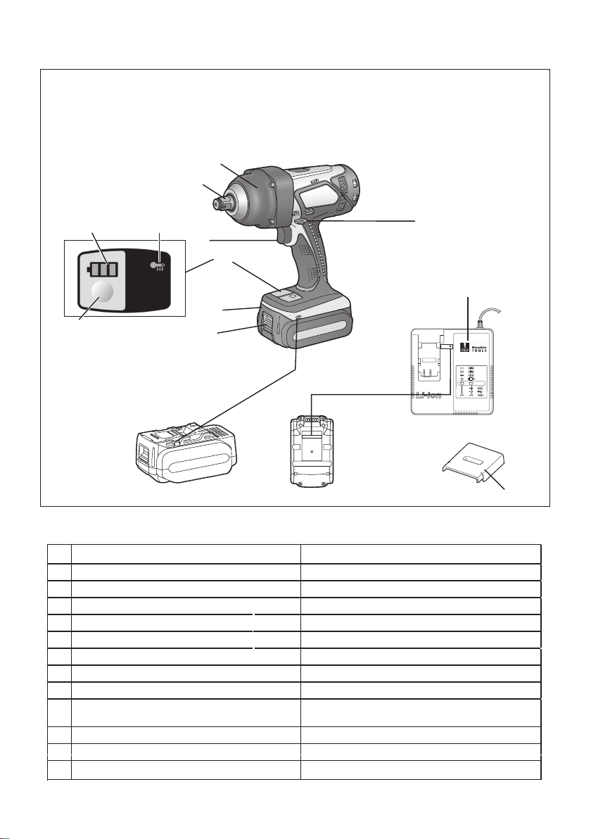
FUNCTIONAL DESCRIPTION
DESCRIPCIÓN FUNCIONAL
(B)
(A)
(I)
(J)
(K)
(G)
(F)
(H)
Square drive (retainer ring and pin)
(A)
Nose protector Protector del morro
(B)
Forward/Reverse lever Palanca de avance/marcha atrás
(C)
Alignment marks Marcas de alineación
(D)
Battery pack release button Botón de liberación de batería
(E)
Battery pack Batería
(F)
Indication panel Panel de indicación
(G)
Battery level button Botón de nivel de batería
(H)
Battery level indicator Indicador de nivel de batería
(I)
Overheat warning lamp (motor/battery)
(J)
Variable speed control trigger
(K)
Battery charger Cargador de batería
(L)
Pack cover Cubierta de batería
(M)
(E)
(D)
Adaptador para puntas (anillo de retención y pasador)
Luz de advertencia de sobrecalentamiento
(motor/batería)
Disparador del control de velocidad variable
(C)
(L)
10.8 V ─ 28.8 V
(M)
Page 3

This tool, as a complete unit with a battery
pack, satisfies appropriate I Degrees of
Protection based on the IEC regulations.
Definition of IP code
IP5X: Ingress of dust is not totally prevented, but dust shall not penetrate in a quantity to interfere with satisfactory operation
of the tool or to impair safety (In case that
the talcum powder under 75 μm intrudes
inside the tool).
IPX6: Water projected in powerful jets
against the tool from any direction shall
have no harmful effects (In case that, with
a nozzle of 12.5 mm inner diameter,
approximately 100 L/min of normal
temperature water is injected to the tool
for 3 minutes from 3 meter distance).
LIMITED WARRANTY
The rating of IP56 qualifies this tool for the
minimum impact of water or dust, but not
for the assurance of performance in such
conditions. See Safety and Operating
Instructions for further details for proper
operation.
I. General Power Tool Safety
Warnings
WARNING! Read all safety
warnings and all instructions. Failure
to follow the warnings and instructions
may result in electric shock, fire and/or
serious injury.
Save all warnings and instructions for
future reference.The term "power tool"
in the warnings refers to your mainsoperated (corded) power tool or
battery-operated (cordless) power tool.
Work Area Safety
3) Keep children and bystanders away
while operating a power tool.
Distractions can cause you to lose
control.
Electrical Safety
1) Power tool plugs must match the
outlet. Never modify the plug in any
way. Do not use any adapter plugs
with earthed (grounded) power
tools.
Unmodified plugs and matchin
outlets will reduce risk of electric
shock.
Avoid body contact with earthed or
2)
grounded surfaces such as pipes,
radiators, ranges and refrigerators.
There is an increased risk of electric
shock if your body is earthed or
grounded.
3) Do not expose power tools to rain
or wet conditions.
Water entering a power tool will
increase the risk of electric shock.
4)
Do not abuse the cord. Never use
the cord for carrying, pulling or
unplugging the power tool. Keep
cord away from heat, oil, sharp
edges or moving parts.
Damaged or entangled cords increase
the risk of electric shock.
5) When operating a power tool
outdoors, use an extension cord
suitable for outdoor use.
Use of a cord suitable for outdoor use
reduces the risk of electric shock.
6) If operating a power tool in a damp
location is unavoidable, use a
residual current device (RCD)
protected supply.
Use of RCD reduces the risk of electrical shock.
Keep work area clean and well lit.
1)
Cluttered or dark areas invite
accidents.
2)
Do not operate power tools in
explosive atmospheres, such as in
the presence of flammable liquids,
Power tools create sparks which may
ignite the dust or fumes.
Page 4

Personal Safety
Newstandardupdate
1) Stay alert, watch what you are
doing and use common sense
when operating a power tool. Do
not use a power tool while you are
tired or under the inuence of
drugs, alcohol or medication.
A moment of inattention while operating power tools may result in personal
injury.
Use personal protective equipment.
2)
Always wear eye protection.
Protective equipment such as dust
mask, non-skid safety shoes, hard hat,
or hearing protection
used for appropriate conditions will
reduce personal injuries.
3)
Prevent unintentional starting.
A moment of inattention while
operating power tools may result in
serious personal injury.
Remove any adjusting key or
4)
wrench before turning the power
tool on.
A wrench or a key left attached to a
rotating part of the power tool may
result in personal
injury.
Do not overreach. Keep proper
5)
footing and balance at all times.
This enables better control of the
power tool in unexpected situations.
6) Dress properly. Do not wear loose
clothing or jewelry. Keep your hair,
clothing and gloves away from
moving parts.
Loose clothes, jewelry or long hair can
be caught in moving parts.
7)
If devices are provided for the
connection of dust extraction and
collection facilities, ensure these
are connected and properly used.
Use of dust collection can reduce
dust-related hazards.
Power Tool Use and Care
1) Do not force the power tool. Use
the correct power tool for your
application.
The correct power tool will do the job
better and safer at the rate for which it
was designed.
2) Do not use the power tool if the
switch does not turn it on and off.
Any power tool that cannot be
controlled with the switch is dangerous and must be repaired.
3)
Disconnect the plug from the
power source and/or the battery
pack from the power tool before
making any adjustments, changing
accessories, or storing power
tools.
Such preventive safety measures
reduce the risk of starting the power
tool accidentally.
Store idle power tools out of the
4)
reach of children and do not allow
persons unfamiliar with the power
tool or these instructions to
operate the power tool.
Power tools are dangerous in the
hands of untrained users.
Maintain power tools. Check for
5)
misalignment or binding of moving
parts, breakage of parts and any
other condition that may affect the
power tools operation. If damaged,
have the power tool repaired before
use.
Many accidents are caused by poorly
maintained power tools.
6)
Keep cutting tools sharp and clean.
Properly maintained cutting tools with
sharp cutting edges are less likely to
bind and are easier to control.
7)
Use the power tool, accessories
and tool bits etc. in accordance
with these instructions, taking into
account the working conditions
and the work to be performed.
Use of the power tool for operations
different from those intended could
result in a hazardous situation.
Page 5

Battery Tool Use and Care
1) Ensure the switch is in the off
position before inserting battery
pack.
Inserting battery pack into power tools
that have the switch on invites accidents.
2) Recharge only with the charger
specied by the manufacturer.
A charger that is suitable for one type
of battery pack may create a risk of
fire when used with another battery
pack.
3) Use power tools only with speci-
cally designated battery packs.
Use of any other battery packs may
create a risk of injury and fire
4) When battery pack is not in use,
keep it away from other metal
objects like paper clips, coins,
keys, nails, screws, or other small
metal objects that can make a
connection from one terminal to
another.
Shorting the battery terminals together
may cause burns, or a fire
5) Under abusive conditions, liquid
may be ejected from battery; avoid
contact. If contact accidentally
occurs, ush with water. If liquid
contacts eyes, additionally seek
medical help.
Liquid ejected from the battery may
cause irritation or burns.
Service
Have your power tool serviced by
1)
a qualified repair person using
only identical replacement
parts.This will ensure that the safety
of the power tool is maintained.
II. SPECIFIC SAFETY
RULES
1) Wear ear protection. Exposure to
noise can cause hearing loss.
2) Be aware that this tool is always in an
operating condition, since it does not
have to be plugged into an electrical
outlet.
3) Hold power tools by insulated gripping
surfaces when performing an operation where the cutting tool may
contact hidden wiring.
Contact with a “live” wire will make
exposed metal parts of the tool “live”
and shock the operator.
4) If the bit becomes jammed, immediately turn the trigger switch off to
prevent an overload which can
damage the battery pack or motor.
Use reverse motion to loosen jammed
bits.
5) Do NOT operate the Forward/Reverse
lever when the trigger switch is on.
The battery will discharge rapidly and
damage to the unit may occur.
6) When storing or carrying the tool, set
the Forward/Reverse lever to the
center position (switch lock).
7) Do not strain the tool by holding the
speed control trigger halfway (speed
control mode) so that the motor stops.
The protection circuit will activate and
may prevent speed control operation.
If this happens, release the speed
control trigger and squeeze again for
normal operation.
8) Be careful not to get dust inside the
chuck.
9) Do not touch the rotating parts to
avoid injury.
10) Do not use the tool continuously for a
long period of time. Stop using the
tool from time to time to avoid
temperature rise and heat overload of
the motor.
11) Do not drop the tool.
Symbol Meaning
Volts
Direct current
No load speed
Revolutions or reciprocations
per minutes
Electrical capacity of battery
pack
To reduce the risk of injury
user must read and under-
stand instruction manual.
Page 6

WARNING:
Some dust created by power sanding,
sawing, grinding, drilling, and other
construction activities contains chemicals known to the State of California to
cause cancer, birth defects or other
reproductive harm. Some examples of
these chemicals are:
• Lead from lead-based paints
• Crystalline silica from bricks and
cement and other masonry products
• Arsenic and chromium from chemically-treated lumber.
To reduce your exposure to these chemicals: work in a well ventilated area, and
work with approved safety equipment,
such as dust masks that are specially
designed to filter out microscopic part cles.
III. FOR BATTERY
CHARGER &
BATTERY PACK
Important Safety Instructions
1) SAVE THESE INSTRUCTIONS—This
manual contains important safety and
operating instructions for battery
charger.
2) Before using battery charger, read all
instructions and cautionary markings
on battery charger, battery pack, and
product using battery pack.
3) CAUTION—To reduce the risk of
injury, charge only Huskie Tools
Battery Pack as shown in last page.
Other types of batteries may burst
causing personal injury and damage.
4) Do not expose charger and battery
pack to rain or snow.
5) To reduce risk of damaging the electric plug and cord, pull by plug rather
than cord when disconnecting charger.
6) Make sure cord is located so that it
will not be stepped on, tripped over, or
otherwise subjected to damage or
stress.
7) An extension cord should not be used
unless absolutely necessary.
Use of improper extension cord could
result in a risk of fire and electri
shock. If extension cord must be
used, make sure that:
a. pins on plug of extension cord are
the same number, size and shape
as those of plug on charger.
b. extension cord is properly wired
and in good electrical condition.
c. wire size is large enough for
ampere rating of charger as specified belo .
RECOMMENDED MINIMUM AWG SIZE OF
EXTENSION CORDS FOR BATTERY CHAR-
AC Input Rating. Amperes AWG Size of Cord
Equal to or
greater than
0 2 18 18 18 16
8) Do not operate charger with damaged
cord or plug—replace them immediately.
9) Do not operate charger if it has
received a sharp blow, been dropped,
or otherwise damaged in any way;
take it to a qualied service personnel.
10) Do not disassemble charger; take it to
a qualified service personnel whe
service or repair is required. Incorrect
reassembly may result in a risk of
electric shock or fire
11) To reduce the risk of electric shock,
unplug charger from outlet before
attempting any maintenance or cleaning.
12) The charger and battery pack are
specifically designed to work togethe .
Do not attempt to charge any other
cordless tool or battery pack with this
charger.
13) Do not attempt to charge the battery
pack with any other charger.
14) Do not attempt to disassemble the
battery pack housing.
GERS
But less
than
Length of Cord,
Feet
25 50 100 150
Page 7

15) Do not store the tool and battery pack
in locations where the temperature
may reach or exceed 50°C (122°F)
(such as a metal tool shed, or a car in
the summer), which can lead to
deterioration of the storage battery.
16) Do not charge battery pack when the
temperature is BELOW 0°C (32°F) or
ABOVE 40°C (104°F). This is very
important in order to maintain optimal
condition of the battery pack.
17) Do not incinerate the battery pack. It
can explode in a fire
18) Avoid dangerous environment. Do not
use charger in damp or wet locations.
19) The charger is designed to operate on
standard household electrical power
only. Do not attempt to use it on any
other voltage!
20) Do not abuse cord. Never carry
charger by cord or yank it to disconnect from outlet. Keep cord away from
heat, oil and sharp edges.
21) Charge the battery pack in a well
ventilated place, do not cover the
charger and battery pack with a cloth,
etc., while charging.
22) Use of an attachment not recommended may result in a risk of fire
electric shock, or personal injury.
23) Do not short the battery pack. A
battery short can cause a large
current flo , over heating and create
the risk of fire or personal injur .
24) NOTE: If the supply cord of this
appliance is damaged, it must only be
replaced by a repair shop authorized
by the manufacturer, because special
purpose tools are required.
25) TO REDUCE THE RISK OF ELECTRIC SHOCK, THIS APPLIANCE
HAS A POLARIZED PLUG (ONE
BLADE IS WIDER THAN THE
OTHER).
This plug will fit in a polarized outle
only one way. If the plug does not fi
fully in the outlet, reverse the plug. If it
still does not fit, contact a qualifi
electrician to install the proper outlet.
Do not change the plug in any way.
WARNING:
• Do not use other than the Huskie Tools
battery packs that are designed for use
with this rechargeable tool.
• Huskie Tools is not responsible for any
damage or accident caused by the use
of recycled or counterfeit battery pack.
• Do not dispose of the battery pack in a
fire, or expose it to excessive heat
• Do not allow metal objects to touch the
battery pack terminals.
• Do not carry or store the battery pack in
the same container as nails or similar
metal objects.
• Do not charge the battery pack in a
high-temperature location, such as next
to a fire or in direct sunlight. Otherwise
the battery may overheat, catch fire, o
explode.
• After removing the battery pack from
the tool or the charger, always reattach
the pack cover. Otherwise, the battery
contacts could be shorted, leading to a
risk of fire
• When the Battery Pack Has Deteriorated, Replace It with a New One. Continued use of a damaged battery pack
may result in heat generation, ignition
or battery rupture.
• To prevent leakage, overheating,
smoke generation, fire, and rupturin
from occurring, follow these instructions
when handling our rechargeable power
tools (tool main body/battery pack/
charger).
- Do not allow material cuttings or dust
to fall onto the battery pack.
- When storing, remove any material
cuttings and dust from the battery
pack, and place the battery pack
separately from metal objects
(screws, nails, etc.) when storing in
the tool case.
• Do not handle the rechargeable power
tools in the following way.
(There is a hazard of smoke generation, fire, and rupturing
- Use or leave in places exposed to
rain or moisture
- Use submerging in water
Page 8

ASSEMBLY
IV.
Attaching or Removing
Bat tery Pack
Attaching or Removing
Sock et
Attaching Socket
1.
1) Remove the rubber ring and pin.
groove
rubber ring
pin
2) Attach the socket putting each holes.
3) Attach the rubber ring and pin in reverse
order of 1).
NOTE:
Attach socket firmly by using pin and
rubber ring.
Retainer ring is only for temporary
fixing.
Removing Socket
2.
1) Remove the rubber ring and pin.
1. To connect the battery pack:
Align the highlighted marker points and
attach battery pack.
• Slide the battery pack until it locks into
position.
Alignment
marks
2. To remove the battery pack:
Push the button and slide the battery pack
forward.
Button
V. OPERATION
WARNING!
• Do not inhale any smoke emitted from the
tool or battery pack as it may be harmful.
[Main unit]
CAUTION
• When storing or carrying the tool, set
the Forward/Reverse lever to the
center position (switch lock).
rubber
ring
pin
NOTE:
Exercise caution to ensure no objects
come into contact with the tool’s
trigger switch.
If an object comes into contact with
the tool’s trigger switch, even while
the Forward/Reverse lever is in the
center position (locked), a small
amount of electric current may
continue flowing, which may cause an
excessive discharge from the battery
pack and subsequent battery pack
failure.
Page 9

Switch and Forward/Reverse
Lever Operation
Forward Reverse
Switch lock
CAUTION:
To prevent damage, do not
operate Forward/Reverse lever until
the socket comes to a complete stop.
Forward Rotation Switch
Operation
1.
Push the lever for forward rotation.
2. Depress the trigger switch slightly to
start the tool slowly.
3. The speed increases with the amount
of depression of the trigger for efficient
tightening of bolts. The brake operates
and the socket stops immediately when
the trigger is released.
4. After use, set the lever to its center
position (switch lock).
Reverse Rotation Switch
Operation
1. Push the lever for reverse rotation.
Check the direction of rotation before
use.
2.
Depress the trigger switch slightly to start
the tool slowly.
3. After use, set the lever to its center
position (switch lock).
CAUTION:
• To eliminate excessive temperature
increase of the tool surface, do not
operate the tool continuously using two
or more battery packs. Tool needs cool
off time before switching to another
pack.
Variable Speed Control
Trigger
To set the center of a hole, pull the
trigger slightly to start the socket
rotation slowly.
control trigger is pulled, the higher the
speed becomes.
CAUTION:
When operating the t
depressing the trigger, there may be a
momentary lag before rotation starts.
This does not signal a malfunction.
Indication pan
(1)
(1) Battery level indicator and button
•
Press the battery level button.
Battery level indicator shows battery
level for approx. 10 seconds.
NOTE:
The indicator
level even the button is pushed in the
following cases.
• The main unit is powered off.
• Just after attaching the battery pack
• The main unit or battery level button
is not operated for approx. one
minute. Push the battery level button
again after depressing the trigger
switch.
• The battery temperature is high.
Stop the operation and wait until
the battery temperature is low.
The more the speed
ool by
el
(2)
will not show the battery
Page 10

Indicator Battery status
3 lamps
illuminated
2 lamps
illuminated
One lamp
illuminated
One lamp
flashin
Charged
enough
Approx. 50%
remaining
Battery level
is low.
Need to be
charged soon
Empty
Need to be
charged
immediately
Battery level indication is just guide.
The indication may change due to
the condition of battery or ambient
temperature.
(2) Overheat warning lamp
Off
(normal
operation)
Illuminated:
Overheat
(motor)
Indicates operation has
been halted due to motor
or battery overheating.
Flashing:
Overheat
(battery)
To protect the motor or battery, be sure to
note the following when carrying out this
operation.
• If the motor or battery becomes hot, the
protection function will be activated and
the motor or battery will stop operating.
The overheat warning lamp on the
indication panel illuminates or flashes
when this feature is active.
• If the overheating protection feature
activates, allow the tool to cool
thoroughly (at least 30 minutes). The
tool is ready for use when the overheat
warning lamp goes out.
• Avoid using the tool in a way that causes
the overheating protection feature to
activate repeatedly.
• If the tool is operated continuously under
high-load conditions or if it is used in hottemperature conditions (such as during
summer), the overheating protection
feature may activate frequently.
• If the tool is used in cold-temperature
conditions (such as during winter) or if
it is frequently stopped during use, the
overheating protection feature may not
activate.
Recommended Grip
Use the grip to hold and operate the
driver with one hand. If the job requires
additional force, you can push against the
rear end of the driver with your other hand.
[Battery Pack]
For Appropriate Use of
Bat tery Pack
Li-ion Battery Pack
•
For optimum battery life, store the Li-ion
battery pack following use without charging it.
• When charging the battery pack, confirm
that the terminals on the battery charger
are free of foreign substances such as dust
and water etc. Clean the terminals before
charging the battery pack if any foreign
substances are found on the terminals.
The life of the battery pack terminals may be
affected by foreign substances such as dust
and water etc. during operation.
• When battery pack is not in use, keep it
away from other metal objects like: paper
clips, coins, keys, nails, screws, or other
small metal objects that can make a
connection from one terminal to another.
Shorting the battery terminals together
may cause sparks, burns or a fire.
• When operating the battery pack, make
sure the work place is well ventilated.
• When the battery pack is removed from the
main unit of the tool, replace the battery
pack cover immediately in order to prevent
dust or dirt from contaminating the battery
terminals and causing a short circuit.
Page 11

Battery Pack Life
The rechargeable batteries have a
limited life. If the operation time becomes
extremely short after recharging, replace
the battery pack with a new one.
Battery Recycling
ATTENTION:
FOR Li-ion Battery Pack
A Li-ion battery that is recyclable powers
the product you have purchased. Please
call 1-800-8-BATTERY for information on
how to recycle this battery.
Recommendations for use
CAUTION:
To protect the motor or battery, be sure
to note the following when carrying out
operation.
●
If the motor and battery becomes hot, the
protection function will be activated and the
motor and battery will stop operating.
For safe use
●
The battery pack is designed to be installed
by proceeding two steps for safety. Make
sure the battery pack is installed properly to
the main unit before use.
●
If the battery pack is not connected firmly
when the switch is switched on, the overheat
warning lamp and the battery low warning
lamp will flash to indicate that safe operation
is not possible, and the main unit will not
rotate normally. Connect the battery pack
into the unit of the tool until the red or yellow
label disappears.
Pack cover
Terminals
Label
Be sure to use the Pack cover
●
When the battery pack is not being used,
store the battery in a way that foreign
substances such as dust and water etc.
do not contaminate the terminals. Be sure
to attach the battery pack cover to protect
the battery terminals.
●
When charging the battery pack, confir
that the terminals on the battery
charger are free of foreign substances
such as dust and water etc. Clean
the terminals before charging the
battery pack if any foreign
substances are found on the
terminals.
The life of the battery pack terminals may
be affected by foreign substances such as
dust and water etc. during operation.
[Battery Charger]
Charging
CAUTION:
1) If the temperature of the battery pack
falls approximately below −10°C
(14°F), charging will automatically
stop to prevent degradation of the
battery.
2) The ambient temperature range is
between 0°C (32°F) and 40°C
(104°F).
If the battery pack is used when the
battery temperature is below 0°C
(32°F), the tool may fail to function
properly.
3) Use the charger at temperatures
between 0°C and 40°C, and charge
the battery at a temperature similar to
that of the battery itself. (There should
be no more than a 15°C difference
between the temperatures of the
battery and the charging location.)
4) When charging a cool battery pack
(below 0°C (32°F)) in a warm place,
leave the battery pack at the place
and wait for more than one hour to
warm up the battery to the level of the
ambient temperature.
Page 12

5) Cool down the charger when charging
more than two battery packs consecu-
tively.
6) Do not insert your fingers into contac
hole, when holding charger or any
other occasions.
7) To prevent the risk of fire or damag
to the battery charger.
• Do not cover vent holes on the charger and the battery pack.
• Unplug the charger when not in use.
NOTE:
Your battery pack is not fully charged at
the time of purchase. Be sure to charge
the battery before use.
How to charge
1. Plug the charger into the AC outlet.
NOTE:
Sparks may be produced when the plug
is inserted into the AC power supply,
but this is not a problem in terms of
safety.
2. Connect the battery pack firmly into th
charger.
1 Line up the alignment marks and
place the battery onto the dock on
the charger.
NOTE:
Not all battery packs display the
alignment mark (Q) (on page 2).
2 Slide forward in the direction of the
arrow. [Fig.6 ]
3. During charging, the charging lamp will
be lit. When charging is completed, an
internal electronic switch will automati-
cally be triggered to prevent overcharging.
• Charging will not start if the battery
pack is hot (for example, immediately
after heavy-duty operation).
The orange standby lamp will be
flashing until the battery cools down
Charging will then begin automatically.
4. The charge lamp (green) will ash
slowly once the battery is approximate-
ly 80% charged.
5. When charging is completed, the
charging lamp in green color will turn
off.
6. If the temperature of the battery pack is
0°C or less, charging takes longer to
fully charge the battery pack than the
standard charging time.
Even when the battery is fully charged,
it will have approximately 50% of the
power of a fully charged battery at
normal operating temperature.
7. Consult an authorized dealer if the
charging lamp (green) does not turn off.
8. If a fully charged battery pack is inserted into the charger again, the charging
lamp lights up. After several minutes,
the charging lamp in green color will
turn off.
9.
Remove the battery pack while the
battery pack release button is held up.
Battery pack
release button
Page 13

LAMP INDICATIONS
Charging is completed. (Full charge.)
Battery is approximately 80% charged.
Now charging.
Charger is plugged into the AC outlet. Ready to charge.
(Green) (Orange)
Turn off Illuminated
MAINTENANCE
VI.
Use only a dry, soft cloth for wiping the unit. Do not use a damp
•
volatile solvents for cleaning.
In the event that the inside of the tool or battery pack is exposed to water, drain and allow to
•
dry as soon as possible. Carefully remove any dust or iron filings that collect inside the
tool. If you experience any problems operating the tool, consult with a repair shop.
TIGHTENING TORQUE
VII.
The power required for tightening a bolt will v
the
as
material
values are provided below.
(They may vary according to tightening conditions.)
being
bolted. Choose the length of tightening time accordingly. Reference
Charging Status Lamp.
Left: green Right: orange will be displayed.
Battery pack is cool.
The battery pack is being charged slowly to reduce the load on
the battery.
Battery pack is warm.
Charging will begin when temperature of battery pack drops. If
the temperature of the battery pack is -10° or less, the charging
status lamp (orange) will also start ashing. Charging will begin
when the temperature of the battery pack goes up.
Charging is not possible. Clogged with dust or malfunction of
the battery pack.
Flashing
cloth, thinner, benzine, or other
ary, according to bolt material and size, as
well
Page 14

Factors Affecting Tightening
Torque
The tightening torque is affected by a wide
variety of factors including the followings.
After tightening, always check the torque
with a torque wrench.
1) Voltage
When the battery pack becomes nearly
discharged, the voltage decreases and the
tightening torque drops.
M16, M20, M24 x 45 mm
Standard bolt
Tightening torque
Tightening time (Sec.)
M16, M20, M24 x 45 mm
High tensile bolt
Bolt
Nut
Washer
Steel plate
hickness 10 mm (3/8”)
t
Washer
Spring washer
Tightening conditions
• The following bolts are used.
Standard bolts: Strength type 4.8
High tensile type 12.9
Explanation of the strength type
4.8
Bolt yield point
(
80% of tensile strength)
32 kgf/mm
Bolt tensile strength
40 kgf/mm
2
(45000 psi)
2
(56000 psi)
2) Tightening time
Longer tightening time results in increased
tightening torque. Excessive tightening,
how ever, adds no value and reduces the
life of the tool.
3) Different bolt diameters
The size of the bolt diameter affects the
tight ening torque.
Generally, as the bolt diameter increases,
tightening torque rises.
4) Tightening conditions
• Tightening torque will vary, even with the
same bolt, according to grade, length, and
torque coefficient (the fixed coefficient indicated by the manufacturer upon production).
Tightening torque
Tightening time (Sec.)
• Tightening torque will vary, even with
the same bolting material (e.g. steel),
accord ing to the surface finish.
• Torque is greatly reduced when the bolt
and nut start turning together.
5) Socket play
Torque is lowered as the six-sided configu-
ration of the socket of the wrong size is
used to tighten a bolt.
6) Switch (Variable speed control trigger)
Torque is lowered if the unit is used with
the switch not fully depressed.
7) Effect of Connecting Adaptor
The tightening torque will be lowered
through the use of a universal joint or a
connecting adaptor.
Page 15

VIII.
IX.
ACCESSORIES
Use only suitable size of socket.
APPENDIX
MAXIMUM RECOMMENDED CAPACITIES
Model
Bolt fastening
Standard bolt : M12 - M20
High tensile bolt : M12 - M18
HTP-IPW
WARRANTY SUPPLEMENT
The breakdown and damage caused by usage consistent for a long time (e.g.: factory work on
the assembly line, etc.) is out of warranty.
X. SPECIFICATIONS
MAIN UNIT
Model
Motor voltage 18 V DC
No load speed 0 - 1550 min
Maximum torque 470 N·m (4160 in-lbs)
Impact per minute 0 - 2400 min
Overall length 214 mm (8-7/16”)
Weight
(with battery pack: BP-185)
HTP-IPW
-1
-1
2.6 kg (5.73 lbs)
Page 16

BATTERY PACK
Model BP-185
Storage battery
Battery voltage
Li-ion Battery
18 V DC (3.6 V x 10 cells)
BATTERY CHARGER
Model
Electrical rating
Weight
Charging time
NOTE: This chart may include models that are not available in your area.
Please refer to the latest general catalogue.
NOTE: For the dealer name and address, please see the included warranty card.
See the rating plate on the bottom of the charger
CH-185
0.93 kg
BP-185
80 min
Federal Communication Commission Interference Statement
This equipment has been tested and found to comply with the limits for a Class B digital
device, pursuant to Part 15 of the FCC Rules. These limits are designed to provide reasonable
protection against harmful interference in a residential installation. This equipment generates,
uses and can radiate radio frequency energy and, if not installed and used in accordance with
the instructions, may cause harmful interference to radio communications. However, there is
no guarantee that interference will not occur in a particular installation. If this equipment does
cause harmful interference to radio or television reception, which can be determined by turning
the equipment off and on, the user is encouraged to try to correct the interference by one of
the following measures:
• Reorient or relocate the receiving antenna.
• Increase the separation between the equipment and receiver.
• Connect the equipment into an outlet on a circuit different from that to which the receiver is
connected.
• Consult the dealer or an experienced radio/TV technician for help.
FCC Caution: To assure continued compliance, install and use in accordance with provided
instructions. Use only the battery pack specified in the instructions. Any changes or
modifications not expressly approved by the party responsible for compliance could void the
user’s authority to operate this equipment.
This device complies with part 15 of the FCC Rules. Operation is subject to the following two
conditions: (1) This device may not cause harmful interference, and (2) this device must accept
any interference received, including interference that may cause undesired operation.
This Class B digital apparatus complies with Canadian ICES-003.
Page 17

X. HARMONIZED STANDARDS
MAIN UNIT
Conforms to UL Std. 60745-1 & 60745-2-2
Certified to CSA Std. C22.2 No. 60745-1 & 60745-2-2
BATTERY CHARGER
Conforms to UL Std. 1310
Certified to CSA Std. C22.2 No. 223-M91
Page 18

Page 19

195 Internationale Blvd
Glendale Heights, IL 60139
Phone 800-860-6170
Fax 800-345-3767
www.huskietools.com
 Loading...