

Page 1
ROOM AIR CONDITIONER
INSTALLATION AND
OPERATING INSTRUCTIONS
MODEL: HQ-2102UH
HQ-2122UH
ENGLISH
Please read these operating instructions thoroughly before using
your air conditioner and keep them for future reference.
For assistance, please call: 1-800-211-PANA (7262) or send e-mail to
consumerproducts@panasonic.com
© 2003 Matsushita Electrical Co., Ltd. All Right Reserved.
or refer to
www.panasonic.com
F564236
Page 2
1
Please observe these following safety precautions when using
your air conditioner.
• Failure or negligence in observing these safety precautions
could cause fire, electrical shock or personal injury.
INSTALLATION PRECAUTIONS
• Due to the weight of this product, we recommend that
you have a helper to assist in the installation. To avoid
injury, use the proper method of lifting. Avoid any sharp
SAFETY PRECAUTIONS
edges.
• Make sure the window frame to be used can
properly support this product.
• This product must be installed in accordance with all local
codes and ordinances.
• Do not install the unit in places where inflammable gas,
fumes or soot may be generated.
OPERATION PRECAUTIONS
• Operate your air conditioner from a stable 115 volt AC
supply.
• Plug into a separate 15 amp grounded outlet only.
• Use of extension cords
Avoid using extension cords. If there are no alternatives,
ensure that the cord is a UL listed 3-wire grounding type,
rated 125 volts with a minimum current-carrying rating of
15 amps, number 14 or heavier wire.
• Use a 15 amp time delay fuse or a circuit breaker.
• Do not switch off by unplugging the power plug while it is
operating. Press the OFF/ON pad to “OFF” before
unplugging.
This symbol (with a white background)
denotes an action that is PROHIBITED.
These symbols (with a blue background) denote
actions that are COMPULSORY.
OPERATION PRECAUTIONS
WARNING
• Do not modify the length of the power cord or use an extension cord.
• Do not touch or operate with wet hands. Do not modify or damage
the cord.
• Do not turn on the unit by inserting the power plug. Do not switch off
the unit by pulling out the power plug.
• Avoid an extended period of direct airflow.
• Do not insert sticks, fingers or other objects into the unit.
• Do not try to repair the unit yourself.
• Plug in properly before operating and use a specified power cord.
• If abnormal conditions (burnt smell, etc) occur, switch off and remove
the power plug.
CAUTION
• Do not use the unit for other purposes, than its intended use.
• Do not remove the power plug by pulling the cord.
• Do not block the air intake and outlet vanes.
• Do not splash or direct water at the unit
• Do not expose the unit to direct sunlight during operation.
• Do not operate the unit without the air filter installed or when the front
intake grille has been removed.
• Do not place any objects on the unit.
• Do not operate any combustion equipment near the unit’s airflow area.
• Switch off the breaker and remove the power plug from the socket if
the unit will not be operated for a long period.
• Pay attention to any damages on the unit caused by extensive usage.
• Ventilate the room occasionally where the unit is installed.
• Remove the power plug when cleaning the unit.
This sign warns of risk of death or serious injury.
This sign warns of injury or damage to property.
POWER SUPPLY
Time Delay Fuse : 15 Amps
Rated Voltage : 115V
• Socket Type
• Line Cord Plug
2
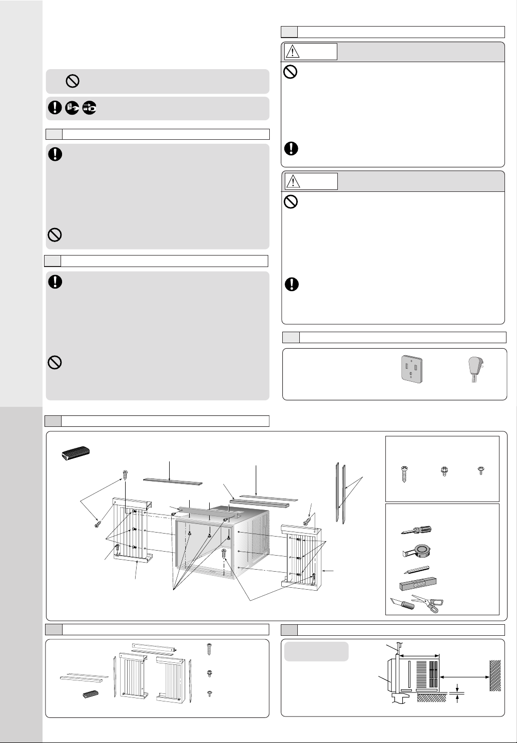
INSTALLATION BOX CONTENTS
Sealer 50 g
(1.8 oz) (Putty)
Type A
screws
Type C screws
Type A screw
Left side
expandable panel
Top sealing
ribbon
To p
angle
Type B screws
ACCESSORIES
AIR CONDITIONER INSTALLATION
NOTE
Check that none of the accessories are missing.
Window sash
foam seal
Type A screws
(6 pcs)
(XTN5D25A)
(5 pcs)
(CWH4580211)
(6 pcs)
(XTT4D8C)
Window sash
sealing ribbon
SCREW FURNISHED
Side
sealing
ribbon
Type A
screw
Type A Type B Type C
(Qty 6) (Qty 5) (Qty 6)
SUGGESTED TOOL LIST
Type C screws
Right side
expandable
panel
SELECT THE BEST LOCATION
(Single or Double
Window
hung window)
Front grille
SIDE VIEW
Wood Machine Tapping
Screw Screw Screw
Medium sized
screwdriver (#2
Phillips)
Tape Measure
Pencil
Level
Knife or
Scissor
19–3/
inches
16
12 inches
More than
4 inches
Page 3
WINDOW REQUIREMENTS
• Hot sun rays hitting the outside surface
of the cabinet will create considerable
heat load. If the outside of the cabinet is
exposed to direct sunlight, consider
building an awning to shade the cabinet
while providing ample area for the heated
air to be exhausted from the condenser
(both sides) and the top.
This unit is designed for installation in
standard double hung windows.
NOTE
The unit may also be installed “through the wall”. You should,
however, observe standard carpentry practices and frame the
opening without violating local ordinances.
INSTALLATION PROCEDURES
CHASSIS INSTALLATION INTO THE CABINET
1 Slide the chassis into the cabinet.
2 Reinstall the cabinet screws.
Secure the cabinet to chassis by using screws (from
rear cabinet).
1 Remove the rear cabinet
screws and save for later use.
2 Slide the chassis out from the
cabinet.
HOW TO ASSEMBLE THE EXPANDABLE PANELS
Top angle
Expandable panel
Type B screws
NOTE
This procedure applies to left and right
Type C screws
of assembling expandable panel.
• Attach the top angle to the cabinet using screw type B (3 pcs).
• Insert expandable panels to cabinet sides as shown.
• Secure the first fold of expansion panel to cabinet using screw
type C (3 each).
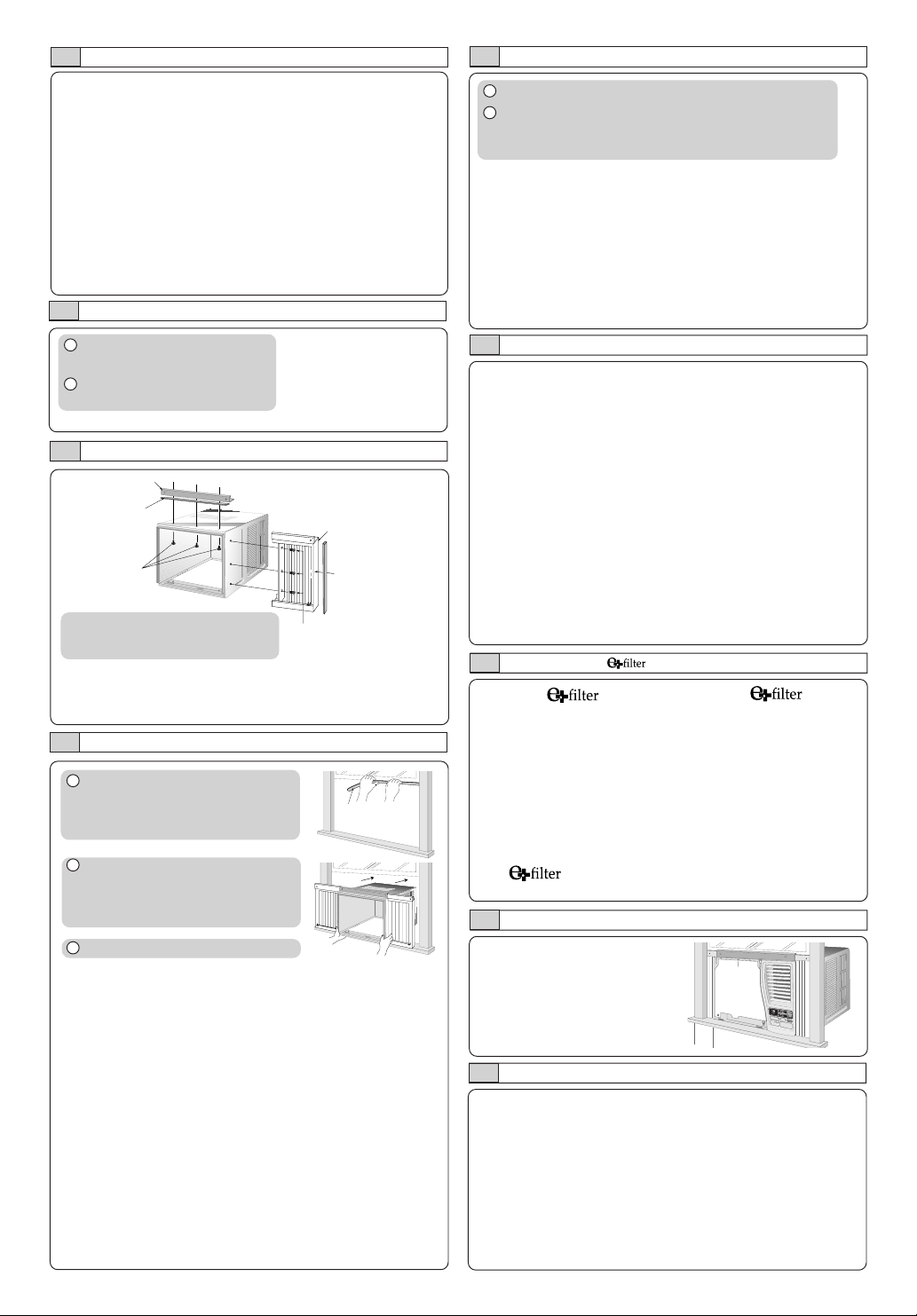
CABINET INSTALLATION
1 Cut the “Sealing Ribbon” to the
proper length, and attach it along
the bottom edge of the bottom
window sash.
Window sash
sealing ribbon
INSTALLATION OF THE FRONT GRILLE
Depending upon the location
of the AC outlet, route the AC
cord to either the left or right
side while installing the front
grille.
This figure shows the AC cord
routed to the left side.
INSERT THE (OPTIONAL)
Attach the (part no.
CZ-SF6P) to the frame.
Slot in the and the
frame (part no. CZ-SFW6P) to
the front grille.
2 To prevent condensation water
from dripping inside, the cabinet
should be installed level or very
slightly tilted to the outside.
3 Secure the cabinet using screws.
• Expand the expandable panel fully into the grooves of the
window frame, secure the expandable panel, left, right and
top mounting frames to the bottom of the window sash
using 6 screws type A and 2 screws type B.
• Secure the cabinet using wood screws type A.
• Cut the window sash foam seal to the proper size and
seal the opening between the top of the inside window
sash and the outside window sash.
Note :If a gap exists between the unit and window sash, you may
use “Sealer” supplied with the installation kit for a better seal.
The and the frame can be obtained separately
from your nearest service center.
INSERT THE AIR FILTER
Attach the air filter to the intake grille
°F
TIM
ER
O
P
E
R
ATIO
N
T
E
M
P
/
T
I
M
E
R
hr
S
E
T
O
S
E
F
T
F
/
/O
N
C
A
N
C
E
L
C
O
O
L
F
A
M
N
O
D
E
A
I
R
S
W
I
N
G
E
C
H
O
I
G
N
H
O
M
Y
M
E
D
F
A
N
S
P
E
E
D
L
O
W
W
ire
less
R
e
m
o
t
e
C
o
n
t
r
o
l
PLACE FRONT INTAKE GRILLE OVER THE FRONT GRILLE
Slide the front intake grille slightly to the right to reattach the
tabs and then push it down to close tight.
Page 4

2
REMOVAL OF FRONT GRILLE
1 Remove the front intake grille.
Pull up the front intake
grille about 90° and slide
it slightly to the left to
unhook the tabs.
3 Remove the front grille.
aa
a
At bottom right side of the front grille, press inward on cabinet near the power cord, and pull
aa
the grille outward to the right until right tab releases.
bb
b
At the bottom left side, push inward on cabinet and pull the grille outward to the left to release
bb
the left tab.
Do not pull the bottom edge toward you more than 3 inches to prevent the two top tabs from
damage.
cc
c
Slide the front grille upwards to free the two top tabs from slots at the top of the cabinet.
cc
HOW TO ATTACH THE DRAIN PAN (OPTIONAL)
AIR CONDITIONER INSTALLATION
Condensed water drainage
This air conditioner employs a “Slinger-Up System” which is designed to splash the condensed
water on the condenser coil for maximum cooling efficiency, thus producing a splashing sound.
If the splashing sound annoys you, you can provide an outside drainage by using the following
procedure which may, however, cause a small loss of performance.
Note: The cabinet should be installed tilted slightly lower to the rear for necessary condensate
drainage. (Max. 13/32”)
1 Remove the rubber plug and slide the chassis out from
the cabinet.
2 Remove the air filter.
Tilt up and pull
out the air filter
by the holder.
Maximum
13/32”
Condensed water
3
Remove the
rubber plug
1 Air inlet louver 4 Air filter (behind the
front intake grille)
2 Cabinet 5 Front intake
grille
3 Power cord 6 Front grille
7 Vertical airflow direction vane
(Airflow direction adjustment updown).
The vertical airflow direction vane
is controlled by rotating the
horizontal vane forward or backward.
PART IDENTIFICATION
Page 5

3
PART
4
ACCESSORIES
• Remote control • Two R03 dry-cell batteries
AIR SWING
IDENTIFICATION
OPERATING
Be sure to observe the following:
• Aim remote control at control
panel on air conditioner when
OPERATION
TEMP/TIMER
SET/
TIMER
CANCEL
ECONOMY
MODE
FAN SPEED
operating.
• Do not drop or throw the remote
control.
• Do not place the remote control
in a location that is exposed to
direct sunlight or next to a heating
°
C
T
I
M
E
O
R
P
E
R
A
T
T
E
IO
M
N
P
/
T
I
M
E
R
h
r
S
E
T
S
E
O
T
F
/
F
/
O
N
C
A
N
C
E
C
L
OO
L
FA
M
N
O
D
E
A
I
R
SWIN
G
HI
GH
P
O
W
E
R
FU
L
FA
N
S
P
E
E
D
L
OW
W
ir
e
l
e
s
R
s
em
o
t
e
C
o
n
t
ro
l
unit or other heat sources.
• Maximum distance : 10 m (32.8 ft.)
PREPARATION BEFORE
Page 6

5
TEMP/TIMER
OFF/ON
OPERATION
OPERATION
TEMP/TIMER
6
ECONOMY OPERATION
To reduce power consumption:
ECONOMY
ECONOMY
°F
hr
• Press ECONOMY.
• To cancel this operation, press once
more.
ECONOMY
Recommended for electricity cost saving. When economy button is
pressed, target temperature is shifted up 1°F, this will reduce operating
time of the compressor and therefore reduce power consumption. It
may, however, take a little longer for the compressor to cycle on and
thereby increase the room temperature slightly. Economy mode will
override your current set fan speed to “LOW”. However, the display will
still show the current set fan speed. Compressor stops when the room
temperature reaches the target temperature. It turns on again when
the room temperature rises. When power failure occurs, the economy
setting is canceled. Once power is resumed, reset the economy setting.
SETTING THE OFF TIMER
When the air conditioner in operation:
TIMER
°F
hr
Press the TIMER button.
The SET/CANCEL indicator light will
AIR CONDITIONER OPERATION
TEMP/TIMER
SET
SET/
CANCEL
blink awaiting for setting.
°F
hr
Press the TEMP/TIMER ▲ or ▼ button
until the preferred hour of operation is
°F
reached.
hr
Press the SET/CANCEL button to
complete the setting. At this time, the
SET/CANCEL indicator light is steady
instead of blinking.
TIMER
NOTE
The hour reading will change back to the
set temperature reading after 10
TEMP/TIMER
SET/
CANCEL
seconds. (You can also revert to
temperature setting immediately by
pressing the TEMP/TIMER ▲ or ▼
buttons again.)
CHECK TIMER SETTING DURING OFF TIMER
Press the TIMER button to check the
°F
remaining programmed timer setting.
TIMER
hr
The figure will be displayed for 10
°F
seconds then will automatically switch
hr
back to temperature setting.
NOTE
TIMER
The timer figure will change according
to the time remaining (if you set it to turn
off 3 hours from now, the timer will show
“2” at an hour later).
CANCEL TIMER SETTING DURING OFF TIMER
SET
SET/
CANCEL
SET/
CANCEL
Model HQ-2102UH HQ-2122UH
COOLING CAPACITY Btu/h 10,000 11,500
ELECTRICAL RATING Phase Single +
EER (Btu/W.h) 10.2 +
MOISTURE REMOVAL (Pints/h) 2.5 3.0
ROOM AIR CIRCULATION (Cf/min) 320 330
DIMENSIONS Height cm (inches) 37.5 (14-
NET WEIGHT kg (lb) 35 (77) +
GROSS WEIGHT kg (lb) 39 (86) +
NOISE LEVEL Indoor (Hi/Lo) dB (A) 50/46 51/47
Press the SET/CANCEL button to cancel
°F
the timer setting. The SET/CANCEL
hr
indicator light will turn off. However the
temperature remains displayed.
Frequency (Hz) 60 +
Voltage (V) 115 +
Current (Amps) 8.7 9.8
Input (W) 980 1120
Width cm (inches) 56 (22Depth cm (inches) 60.6 (23-27/32˝) +
Outdoor (Hi/Lo) dB (A) 57/54 58/55
* Specifications are subject to change without notice for further improvement.
PRODUCT SPECIFICATIONS
SETTING THE ON TIMER
When the air conditioner in operation:
TIMER
°F
hr
Press the TIMER button. The TIMER
indicator light will blink to await for setting.
°F
SET
SET/
CANCEL
Press the TEMP/TIMER
hr
until the desired hour for operation is
reached. Press the SET/CANCEL button
°F
to complete the setting. At this time, the
hr
TIMER indicator light is steady instead of
blinking.
°F
The display will show the remaining hour
hr
to the start of the operation (if you set to
▲ or ▼
turn on 3 hours from now, the timer will
show “2” at an hour later).
TIMER
When set time is reached, the air
conditioner starts the operation under the
previous setting mode and the TIMER
indicator will light off. Now, the previous
SET/
CANCEL
set mode and the fan speed will light up.
Simultaneously, the display will show the
setting temperature.
CHECK TEMPERATURE/MODE/FAN SPEED
SETTING DURING ON TIMER
Press the TIMER button. The TIMER
TIMER
°F
indicator light will blink and the previous
hr
temperature setting will be shown.
°F
Simultaneously, MODE and FAN
hr
SPEED indicator will light up. This
indication will last for 5 seconds, and
then the display will show the remaining
time. MODE and FAN SPEED indicator
TIMER
light will turn off. At this time, the TIMER
indicator light is steady instead of
blinking.
CHANGE TEMPERATURE/MODE/FAN SPEED
SETTING DURING ON TIMER
SET/
CANCEL
OPERATION
OFF/ON
TIMER
SET
SET/
CANCEL
TIMER
Press the SET/CANCEL button to
°F
hr
cancel the timer setting.
Press the OPERATION. Set the desired
°F
mode and the fan speed. Then press
hr
OPERATION button to stop operation.
Start the TIMER setting again by
°F
repeating the step from the “Setting the
hr
on timer” procedures).
CANCEL TIMER SETTING DURING ON TIMER
SET
SET/
CANCEL
SET/
CANCEL
OPERATION
Press the SET/CANCEL button to cancel the
°F
timer setting. The SET/CANCEL indicator
hr
light will turn off. To operate the air
°F
conditioner before reaching the set timer:
hr
• Press the SET/CANCEL to cancel the
timer.
• Press the OPERATION button to turn on
the unit.
25
/32˝) +
1
/16˝) +
button
Page 7

7
Random Auto Restart
• Operation will automatically
• If the unit was set to TIMER
Timer Setting
• When power failure occurs, the
ENERGY SAVING HINTS
HELPFUL INFORMATION &
HELPFUL INFORMATION
resume under the previous
operation mode.
mode, operation will not resume
automatically.
timer setting is canceled. Once
power returns, reset the timer.
ENERGY SAVING HINTS
• Setting the temperature 1°F higher save
10% electricity costs.
• Clean the air filter every 2 weeks. Regular
cleaning of the air filter preserves efficiency.
• Keeping openings closed keeps cool air in
and hot air out.
• Avoid direct sunlight and heat.
• For health reasons do not overcool your
room.
• Your air conditioner’s cooling capacity
should match your room size.
Page 8

Panasonic Consumer Electronics Company,
Division of Matsushita Electric Corporation
of America
One Panasonic Way
Secaucus, New Jersey 07094
Panasonic Sales Company,
Division of Matsushita Electric of Puerto Rico, Inc.,
Ave. 65 de Infanteria, Km. 9.5
San Gabriel Industrial Park
Carolina, Puerto Rico 00985
Quasar Room Air Conditioner
Limited Warranty
Panasonic Consumer Electronics Company or Panasonic Sales Company (collectively referred to as “the Warrantor”) will repair this
product with new or refurbished parts in case of defects in material or workmanship, free of charge, in the USA or Puerto Rico in accordance
to the following (All time periods start from the date of the original purchase).
SEALED REFRIGERATING SYSTEM (compressor and interconnecting tube): FIVE (5) YEARS - PARTS AND LABOR
ALL OTHER COMPONENTS: ONE (1) YEAR - PARTS AND LABOR
In-home service in the USA can be obtained during the warranty period by contacting a Panasonic Service Company (PASC) Factory
Servicenter listed in the Servicenter Directory. Or call toll free, 1-800-211-PANA(7262), to locate a PASC authorized Servicenter. In-home
service in Puerto Rico can be obtained during the warranty period by calling the Panasonic Sales Company telephone number listed in the
Servicenter Directory.
Note: If the unit is installed at the other than normal window height and/or has been
custom-installed (e.g., through the wall), the customer is responsible for removing
the unit from its installation prior to the performance of in-home service.
This warranty is extended only to the original purchaser. A purchase receipt or other proof of date of the original purchase is required for
service and parts replacement under this warranty.
This warranty only covers failures due to defects in materials and workmanship and does not cover normal wear or cosmetic damage. The
warranty does not cover damages which occur in shipment, or failures which are caused by products not supplied by the warrantor, or
failures which result from accident, misuse, abuse, neglect, mishandling, misapplication, faulty installation, maladjustment of customer
controls, improper maintenance, alteration, modification, power line surge, lightning damage, improper voltage supply, commercial use
such as hotel, office, restaurant, or other business or rental use of the product, or service by anyone other than a PASC Factory Servicenter
or a PASC authorized Servicenter, or damage that is attributable to acts of God.
LIMITS AND EXCLUSIONS
There are no express warranties except as listed above.
THE WARRANTOR SHALL NOT BE LIABLE FOR INCIDENTAL OR CONSEQUENTIAL DAMAGES RESULTING FROM THE
USE OF THIS PRODUCT, OR ARISING OUT OF ANY BREACH OF THIS WARRANTY. ALL EXPRESS AND IMPLIED
WARRANTIES, INCLUDING THE WARRANTIES OF MERCHANTABILITY, ARE LIMITED TO THE APPLICABLE WARRANTY
PERIOD SET FORTH ABOVE.
Some states do not allow the exclusion or limitation of incidental or consequential damages, or limitations on how long an implied
warranty lasts, so the above exclusions or limitations may not apply to you.
This warranty gives you specific legal rights and you may also have other rights which vary from state to state. If a problem with this
product develops during or after the warranty period, you may contact your dealer or Servicenter. If the problem is not handled to your
satisfaction, then write to the Consumer Affairs Department at the company address indicated above.
SERVICE CALLS WHICH DO NOT INVOLVE DEFECTIVE MATERIALS OR WORKMANSHIP AS DETERMINED
BY THE WARRANTOR, IN ITS SOLE DISCRETION, ARE NOT COVERED. COSTS OF SUCH SERVICE CALLS ARE
THE RESPONSIBILITY OF THE PURCHASER.
[For assistance, please call: 1-800-211-PANA (7262) or send e-mail to consumerproducts@panasonic.com]
Printed in Malaysia
F0310-0
F564236
 Loading...