

Page 1

Digital Video Cassette Recorder
Operating Instructions
(Software)
AJ-
E
P
Page 2

Contents
Menu screen transitions. . . . . . . . . . . . . . 4
Turning on the power. . . . . . . . . . . . . . . . 7
HOME menu displays . . . . . . . . . . . . . . . 8
HOME menu . . . . . . . . . . . . . . . . . . . . . 13
HOME SET UP menu . . . . . . . . . . . . . . 17
VIDEO IN menu . . . . . . . . . . . . . . . . . . . 22
VIDEO OUT HD menu. . . . . . . . . . . . . . 24
VIDEO OUT HD SET UP menu. . . . . . . 26
VIDEO OUT HD SET UP STATE
menu. . . . . . . . . . . . . . . . . . . . . . . . . . 28
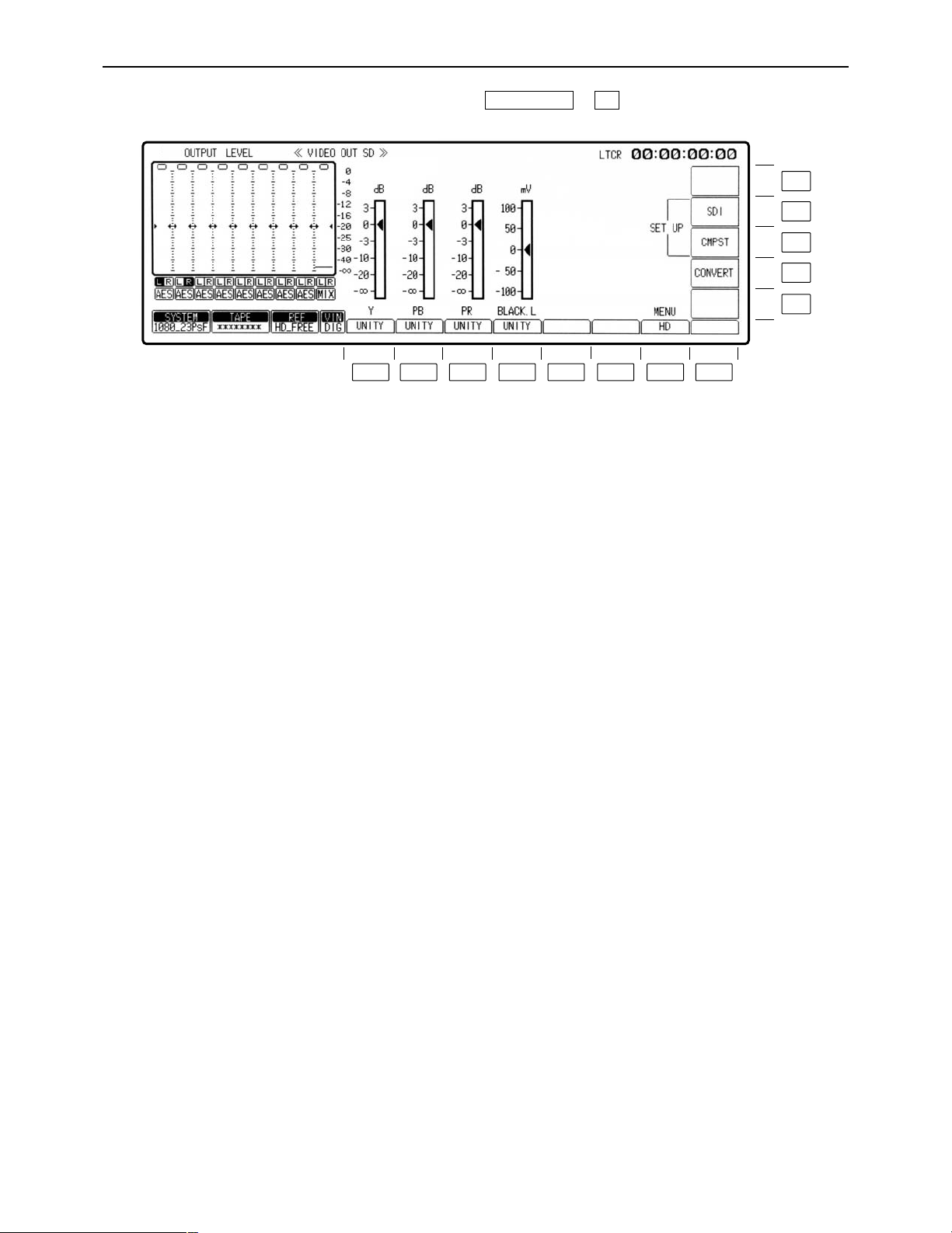
VIDEO OUT SD menu . . . . . . . . . . . . . . 30
VIDEO OUT SD SET UP COMPOSITE
menu. . . . . . . . . . . . . . . . . . . . . . . . . . 32
VIDEO OUT SD SET UP CMPST
STATE menu . . . . . . . . . . . . . . . . . . . 34
VIDEO OUT SD SET UP SDI menu . . . 36
VIDEO OUT SET UP LINE BLK
(video output line blanking) menu. . . . 38
VIDEO OUT SD SET UP SDI STATE
menu. . . . . . . . . . . . . . . . . . . . . . . . . . 40
VIDEO OUT CONVERT menu . . . . . . . 42
VIDEO OUT CONVERT HD_TO_SD
menu. . . . . . . . . . . . . . . . . . . . . . . . . . 43
VIDEO OUT CONVERT SD_TO_HD
menu. . . . . . . . . . . . . . . . . . . . . . . . . . 44
VIDEO OUT CONVERT HD_TO_HD
menu. . . . . . . . . . . . . . . . . . . . . . . . . . 45
AUDIO IN menu . . . . . . . . . . . . . . . . . . . 46
AUDIO IN PCM INPUT SELECT menu. . 48
AUDIO IN CUE INPUT SELECT
menu. . . . . . . . . . . . . . . . . . . . . . . . . . 51
AUDIO IN SET UP menu. . . . . . . . . . . . 53
AUDIO IN CH-MIX SELECT menu . . . . 55
AUDIO OUT menu. . . . . . . . . . . . . . . . . 58
AUDIO OUT MONITOR menu. . . . . . . . 60
AUDIO OUT SET UP menu. . . . . . . . . . 62
AUDIO OUT SET UP STATE menu . . . 66
AUDIO OUT SDI ASIGN menu . . . . . . . 68
TC/CHR menu . . . . . . . . . . . . . . . . . . . . 70
TC/CHR SET UP menu . . . . . . . . . . . . . 76
TC/CHR SET UP VITC.L menu . . . . . . . 78
TC/CHR CONVERT menu. . . . . . . . . . . 80
MULTI CUE menu . . . . . . . . . . . . . . . . . 81
MULTI CUE SET UP menu . . . . . . . . . . 85
INSERT/ASSEMBLE MANUAL EDIT
menu. . . . . . . . . . . . . . . . . . . . . . . . . . 87
INSERT/MANUAL EDIT CH SELECT
menu. . . . . . . . . . . . . . . . . . . . . . . . . . 88
INSERT/ASSEMBLE MANUAL EDIT
SET UP menu. . . . . . . . . . . . . . . . . . . 90
INSERT/ASSEMBLE AUTO EDIT
menu. . . . . . . . . . . . . . . . . . . . . . . . . . 98
INSERT AUTO EDIT CH SELECT
menu. . . . . . . . . . . . . . . . . . . . . . . . . 105
INSERT/ASSEMBLE AUTO EDIT
SET UP menu. . . . . . . . . . . . . . . . . . 107
– 2 –
Page 3

Contents
SET UP menu . . . . . . . . . . . . . . . . . . . 111
INTERFACE SET UP menu . . . . . . . . 112
PANEL SET UP menu . . . . . . . . . . . . . 118
PANEL SET UP (OP MAP REMOTE)
menu. . . . . . . . . . . . . . . . . . . . . . . . . 120
PANEL SET UP (OP MAP LOCAL)
menu. . . . . . . . . . . . . . . . . . . . . . . . . 123
USER SET UP menu. . . . . . . . . . . . . . 125
SYSTEM SET UP menu . . . . . . . . . . . 130
ENGINEER SET UP menu . . . . . . . . . 136
OPERATION ENGINEER SET UP
menu. . . . . . . . . . . . . . . . . . . . . . . . . 137
TEST menu . . . . . . . . . . . . . . . . . . . . . 138
RF TEST menu . . . . . . . . . . . . . . . . . . 140
RF adjustment value display menu . . . 143
AUDIO TEST menu . . . . . . . . . . . . . . . 144
MECHA TEST menu . . . . . . . . . . . . . . 145
SYSTEM TEST menu . . . . . . . . . . . . . 147
SERVO TEST menu . . . . . . . . . . . . . . 148
TEST FRONT menu . . . . . . . . . . . . . . 151
TEST FRONT PANEL menu . . . . . . . . 152
TEST FRONT KEY CHECK menu . . . 153
Inserting the IC card . . . . . . . . . . . . . . 155
TEST IC CARD menu . . . . . . . . . . . . . 156
TEST IC CARD USER menu. . . . . . . . 157
TEST IC CARD MULTI CUE menu . . . 158
TEST IC CARD MULTI CUE SELECT
menu. . . . . . . . . . . . . . . . . . . . . . . . . 159
TEST IC CARD MULTI CUE MONITOR
menu. . . . . . . . . . . . . . . . . . . . . . . . . 160
TEST IC CARD ERROR LOG
menu. . . . . . . . . . . . . . . . . . . . . . . . . 161
TEST IC CARD ERROR LOG MONITOR
menu. . . . . . . . . . . . . . . . . . . . . . . . . 162
Error messages . . . . . . . . . . . . . . . . . . 163
DIAG menu error messages . . . . . . . . 164
DIAG ACTIVE menu . . . . . . . . . . . . . . 165
DIAG MASKED menu . . . . . . . . . . . . . 166
DIAG LAST menu . . . . . . . . . . . . . . . . 167
DIAG error messages . . . . . . . . . . . . . 168
AUTO OFF error messages. . . . . . . . . 172
SYSTEM error messages . . . . . . . . . . 174
Operation messages . . . . . . . . . . . . . . 176
Operation messages (in AUTO EDIT
mode) . . . . . . . . . . . . . . . . . . . . . . . . 177
Screen saver function . . . . . . . . . . . . . 178
List of menu screen displays . . . . . . . . 179
INDEX . . . . . . . . . . . . . . . . . . . . . . . . . 195
– 3 –
Page 4
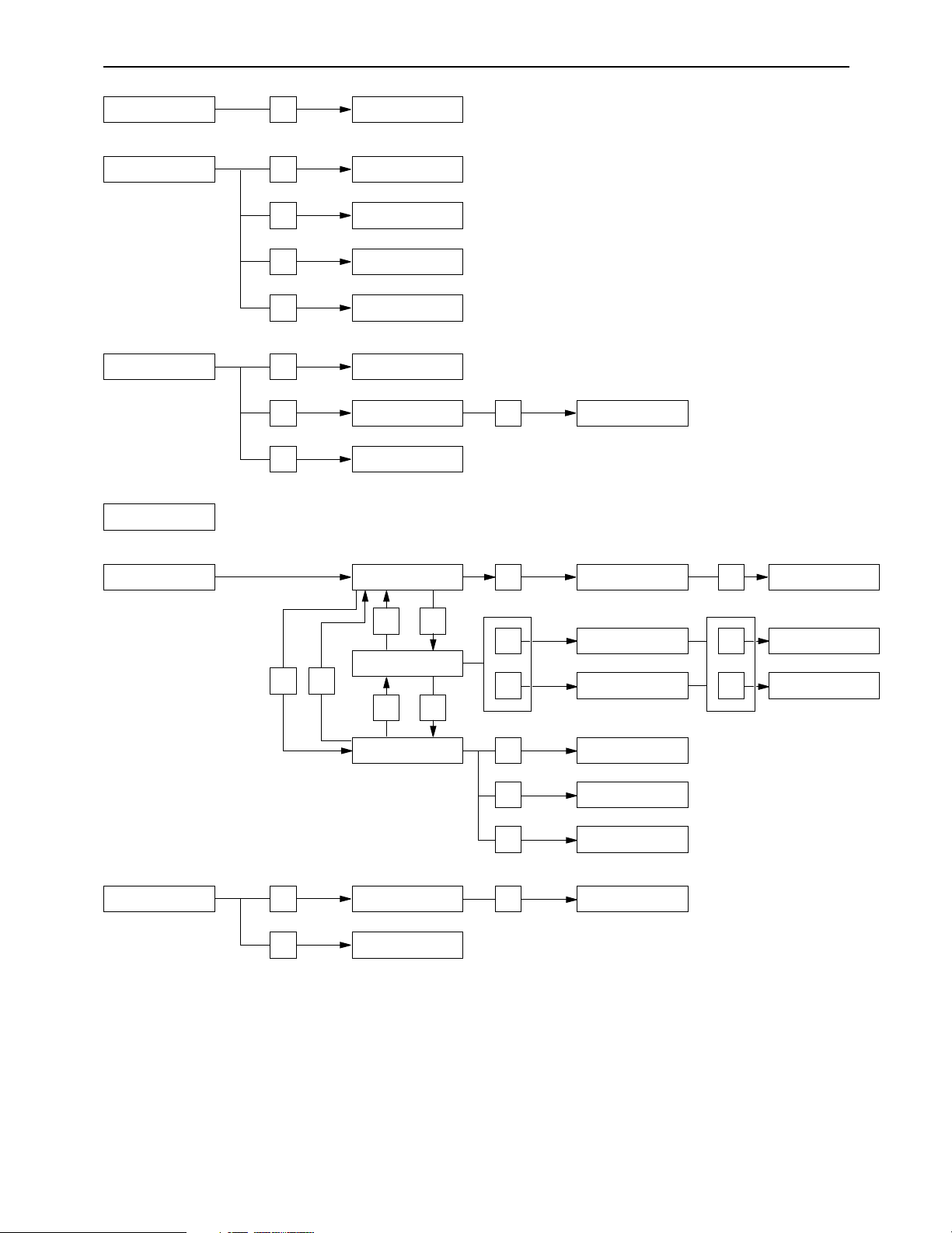
Menu screen transitions
HOME F8 HOME SET UP
AUDIO IN F6
AUDIO IN PCM INPUT
SELECT
AUDIO IN CUE INPUT
SELECT
F7
F8 AUDIO IN SET UP
AUDIO OUT F7
AUDIO OUT MONITOR
VIDEO IN
F7
F7
F10
F9
F9 F10
F11
F12
F1
F2
F3
VIDEO OUT CONVERT
HD_TO_SD
VIDEO OUT CONVERT
SD_TO_HD
VIDEO OUT CONVERT
HD_TO_HD
F9
F11
F12
F8
VIDEO OUT VIDEO OUT HD
VIDEO OUT HD SET UP
TC/CHR F8
F9
TC/CHR SET UP VITC.L
TC/CHR CONVERT
VIDEO OUT SD
VIDEO OUT CONVERT
VIDEO OUT SD SETUP
CMPST
VIDEO OUT SD SETUP
SDI
LINE BLK
STAT E
STAT E
F12
F8
AUDIO OUT SET UP
F12
AUDIO OUT SET UP
STAT E
F9
AUDIO OUT SDI ASIGN
F9
AUDIO IN CH-MIX
SELECT
– 4 –
Page 5
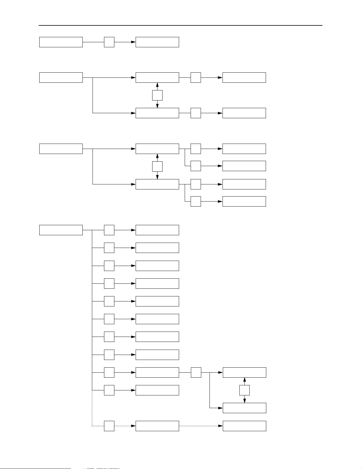
Menu screen transitions
MULTI CUE
F8
MULTI CUE SET UP
ASSEMBLE
ASSEMBLE MANUAL
EDIT
F8
ASSEMBLE MANUAL
EDIT SET UP
F12
F12
F1
F2
F3
F4
F5
F6
F7
F10
F11
F11
F13
F12
HOME SET UP
INSERT/ASSEMBLE
MANUAL EDIT SET UP
INSERT/ASSEMBLE
AUTO EDIT SET UP
SYSTEM SET UP
TC/CHR SET UP
AUDIO IN SET UP
AUDIO OUT SET UP
INTERFACE SET UP
PANEL SET UP
USER SET UP
F13
ENGINEER OPERATION
ASSEMBLE AUTO EDIT
ASSEMBLE AUTO EDIT
SET UP
F8
F8
F8
F13
F13
INSERT
INSERT MANUAL
EDIT
INSERT MANUAL
EDIT SET UP
INSERT MANUAL
EDIT CH SELECT
INSERT AUTO EDIT
INSERT AUTO EDIT
SET UP
INSERT AUTO EDIT
CH SELECT
SET UP
OP MAP LOCAL
OP MAP REMOTE
– 5 –
Page 6
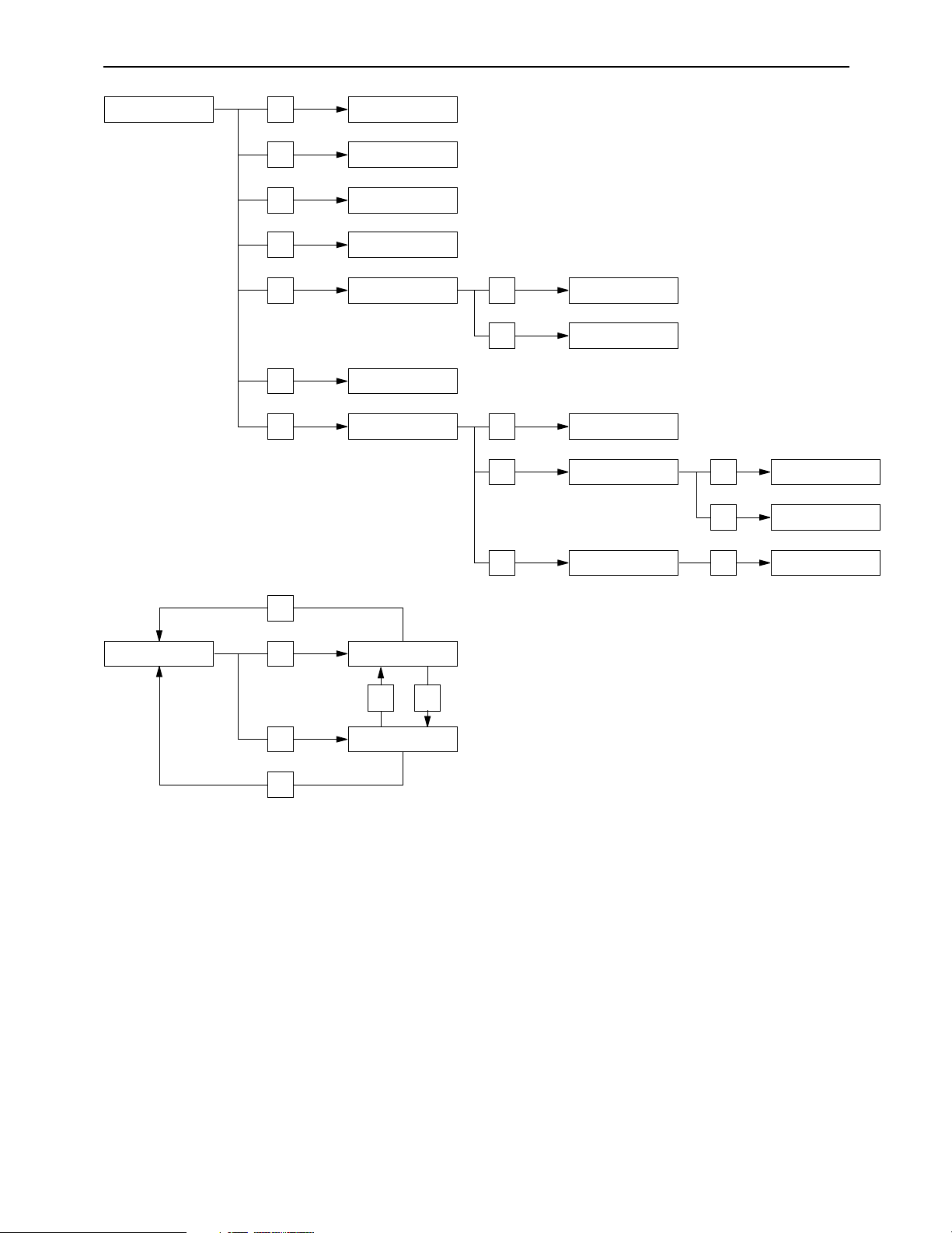
Menu screen transitions
TEST
F2
RF
DIAG
F2
DIAG MASKED
F3
DIAG LAST
F3
AUDIO
F4 MECHA
F5 SYSTEM
F6 FRONT
F7
F1
F1
SERVO
F13 IC CARD
F1 USER
MULTI CUE
ERROR LOG
F2
F1
TEST FRONT PANEL
F2
TEST FRONT KEY
CHECK IO
F1
F2
SELECT
MONITOR
MONITOR
F3
F3
F2 F3
– 6 –
Page 7
Turning on the power
F13
F12
F11
F10
F9
F8F7F6F5F4F3F2F1
Turn on the power.
«
The HOME menu is displayed.
This VTR comes already programmed with menus that correspond to specific operating objectives, and the
operations performed on each differ from one menu to another. When a menu is selected using a menu selection button, what appears on the display changes, and the function keys (F1 to F13) also implement the
function corresponding to the respective menu items.
SET UP menus are provided in order for the user to have settings on hand for the seldom used functions, etc.
among the various menu items.
The HOME menu is provided as the VTR’s basic menu. It automatically appears on the display when the
power has been turned on. (However, the IC CARD menu will automatically appear if an IC card has been inserted.)
– 7 –
Page 8
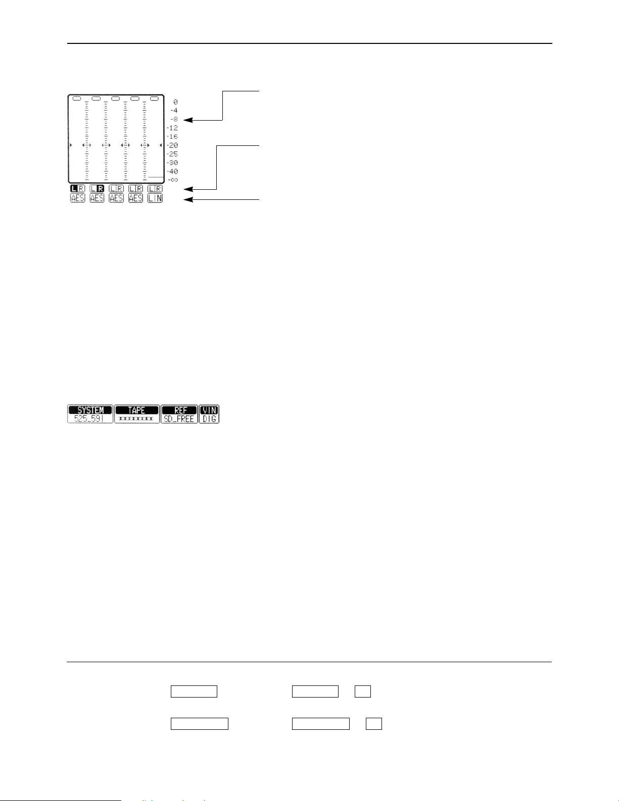
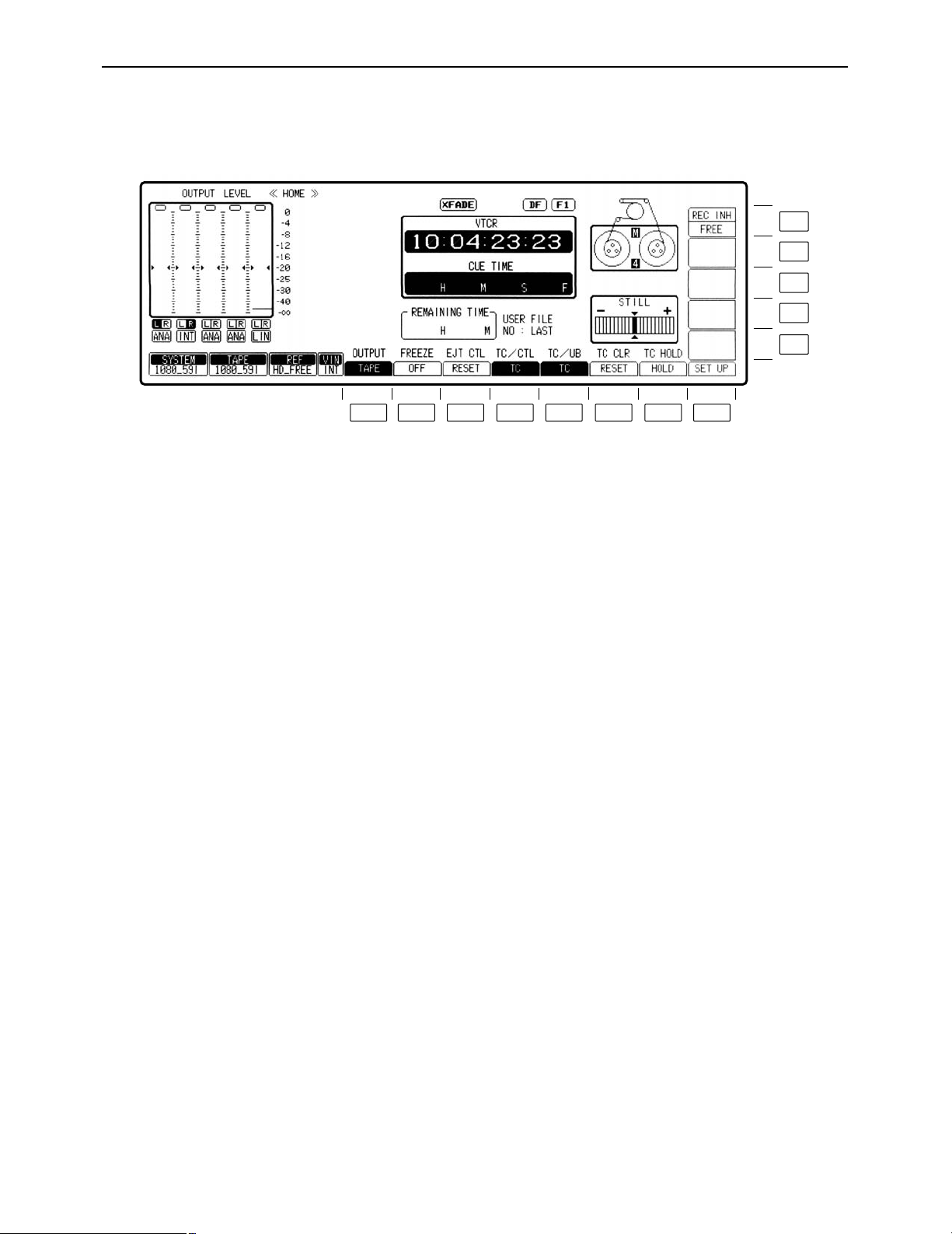
HOME menu displays
∑ Audio signal display area (Either 8 or 4 channels will be automatically displayed depending on the
format used.)
Use this to adjust the level of the input audio signals on the AUDIO
IN menu. Alternatively, it is used to adjust the level of the audio
playback output signals on the AUDIO OUT menu.
Press the L/R buttons to select the audio channel whose signals
are to be output from the AUDIO MONITOR L/R connectors and
HEADPHONES jack.
These display the type of input signals of each channel.
The F1 (CH-1) to F6 (DIGITAL) [or F1 (CH-1) to F13 (CH-8) for 8
channels] on the AUDIO IN PCM INPUT SELECT menu are selected using the F9 (CH-MIX) key on the AUDIO IN CUE INPUT
SELECT menu.
[----
ANA: Signals from the ANALOG INPUT connectors.
∑ Display lamps
CH1 AES:
T
CH1 SER: Signals from the serial V/A input connectors.
{---- INT: Signals from the internal signal generator.
[----
LINE: Signals from the CUE IN connector.
CUE MIX: CH1 to CH8 signals selected by CUE MIX setting.
{---- AUTO: This is always used for digital channel backup pur-
Signals from the DIGITAL AUDIO INPUT connectors.
poses.
SYSTEM: This indicates the video system format which was set
on the SETUP/SYSTEM menu.
1080_59i
525_59i
1080_23psf
1080_24psf
720_59p
1080_50i
TAPE: This indicates the format of the playback tape.
“¢¢¢¢¢¢¢¢” appears in the EJECT mode.
If a section is unrecorded or if the format of a section
cannot be identified, the lamp blinks while the display
of the format identified up to the section concerned is
retained.
1080_59i, 1080_60i
1035_59i, 1035_60i
525_59i
1080_23p, 1080_24p
720_59p, 720_60p
1080_50i
How to display the ≥AUDIO IN menu: ≥AUDIO IN PCM INPUT SELECT menu:
menus:
≥AUDIO OUT menu: ≥AUDIO IN CUE INPUT SELECT menu:
AUDIO OUTAUDIO OUT
#
#
F6AUDIO INAUDIO IN
F7
– 8 –
Page 9

HOME menu displays
REF: This indicates the status of the output reference signal
which has been selected by the VTR.
HD REF59: HD REF with a field frequency of 59.94 Hz is
selected.
HD REF47: HD REF with a field frequency of 47.96 Hz is
selected.
HD REF48: HD REF with a field frequency of 48.00 Hz is
selected.
HD REF50: HD REF with a field frequency of 50.00 Hz is
selected.
SD REF59: The NTSC signal is selected as the SD REF
signal.
SD REF50: The PAL signal is selected as the SD REF sig-
nal.
HD IN59: The HD serial input with a frame frequency of
29.97 Hz is selected as the REF signal.
HD IN47: The HD serial input with a frame frequency of
23.98 Hz is selected as the REF signal.
HD IN48: The HD serial input with a frame frequency of
24.00 Hz is selected as the REF signal.
HD IN50: The HD serial input with a frame frequency of
25.00 Hz is selected.
SD IN: The SD serial input is selected as the REF sig-
nal. (SD IN can be selected only when 525i has
been selected as the VTR’s system format.)
HD FREE: The HD internal signal generator is used since
no REF signal has been selected using the
OUT REF setting.
SD FREE: The SD internal signal generator is used since
no REF signal has been selected using the
OUT REF setting.
*DUAL: HD REF47 and SD REF59 have been selected
simultaneously.
This setting takes effect when 1080/23psf has
been selected as the VTR’s system format,
AUTO has been selected by the OUT REF setting, and two of the above REF signals have
been input.
°This VTR uses the HD REF and SD REF sig-
nals as a reference for entering the 24 # 60
conversion inside the unit.
– 9 –
Page 10
HOME menu displays
INPUT CHECK
TCG
00 : 41 : 07 : 04
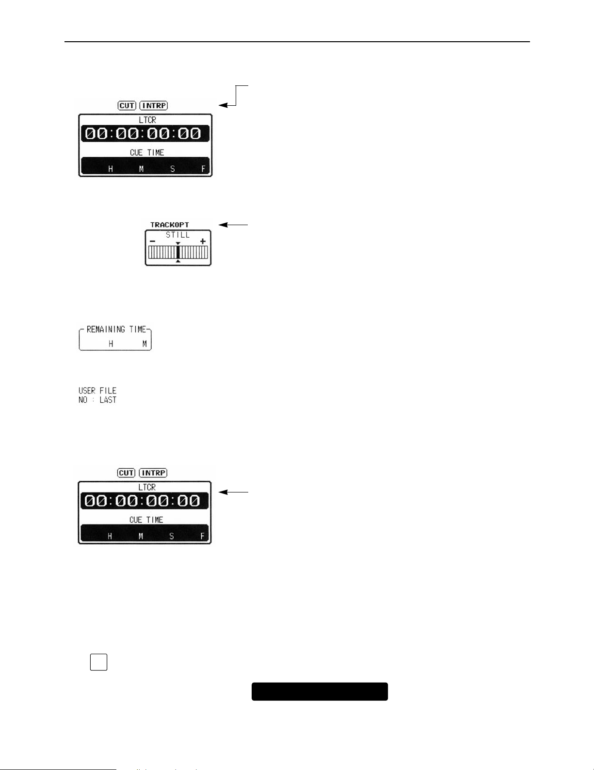
∑ Setting mode display area
∑ Remaining tape time
The displays appearing in this area indicate the modes which
have been set.
CUT: Appears when the audio cut editing mode is set.
XFADE: Appears when the audio cross-fade editing mode
is set.
VFADE: Appears when the audio V fade editing mode is
set.
INTRP: Appears when the time code interpolation mode (in
which the time code cannot be read out accurately) is established.
DF: Appears when the drop frame mode is set.
F1/F2: Indicates the field numbers for VITC.
EMPHASIS: Appears when pre-emphasis is applied to the
audio signals.
TRACK VAR: Appears when an adjustment has been made with
the tracking deviated from the fixed position.
TRACK OPT: Appears when an optimizing adjustment has been
made for the tracking.
∑ User file display
∑ Time code displays
This indicates the remaining tape time as the tape travels.
This indicates the number of file which is called when the power is
switched on or the currently called user file. If there is a discrepancy between the contents of the user file displays and even one
current setting, “¢” will appear in front of the file number.
These indicate the time code values.
CTL1: Normal control signal
CTL2: Control signal (which cannot be reset)
LTCR: LTC readout
LUBR: LTC user bit readout
VTCR: VITC readout
VUBR: VITC user bit readout
TCG: Value generated by generator
LUBG: Value of LTC user bit generated
VUBG: Value of VITC user bit generated
E-TC: External time code
E-UB: External user bit
∑ Checking the value generated by generator
Press the INPUT CHECK key. While the key is held down, the
value generated by the generator is displayed.
– 10 –
Page 11

HOME menu displays
LTCR
00 : 00 : 00 : 00
1 0 0 0
0 0
F 9
0
LUBR
10 : 00 : 00 : 0F
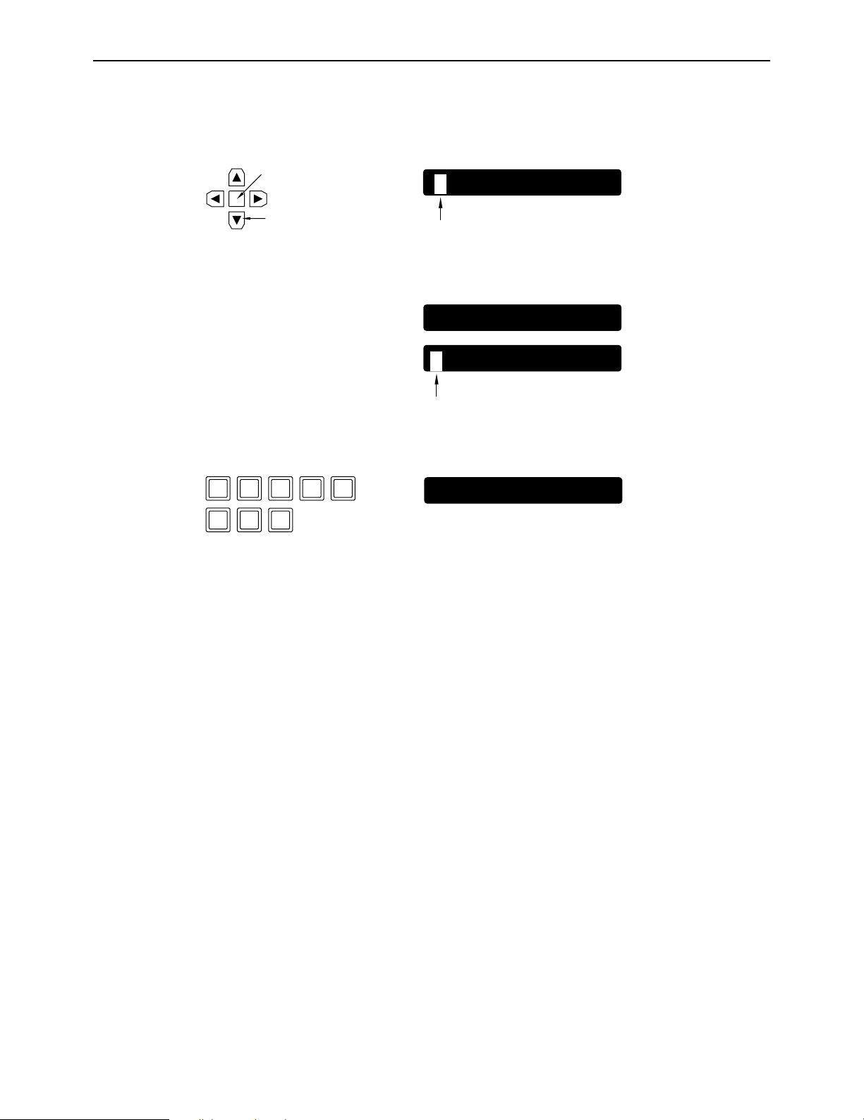
∑ Setting the initial value for the time code
(1) Press the center cursor key.
The display now appears in reverse video.
Center cursor key
(2) Press the center cursor key again so that the cursor is made to serve as a column cursor,
and then use the number key to input the value.
To set a letter from A to F in the initial value of the user bit, simultaneously press the F key and the corresponding number key
(4 to 9).
(3) Press the ENT key.
The cursor is now cleared. (This completes the setting of the initial value.)
≥To clear the value entered, press the C key in step (2).
≥To check the value which has been input, press the INPUT CHECK key.
– 11 –
Page 12
HOME menu displays
LTCR
10 : 00 : 00 : 00
CUE TIME
HMS F
LTCR
10 : 00 : 00 : 00
0 0 4 1 0
7 0
4
CUE TIME
00 H 41 M 07 S 04 F
∑ Setting and checking the cue time
(1) Press the center cursor key.
The time code display now appears in reverse video.
Center cursor key
Cursor key
(2) Press the [4] cursor key.
The cue time now appears in reverse video.
(3) Press the center cursor key again so that the cursor is made to serve as a column cursor,
and then use the number keys to input the value.
(4) Press the ENT key.
The cursor is now cleared. (This completes the setting of the cue time.)
(5) Press the PREROLL button.
The cue time on the tape is searched, and the tape is prerolled for the cue time, after which
it stops.
Cursor
Cursor
≥When the ENTRY button is pressed, the tape’s current position is automatically input.
≥Pressing the F key and PREROLL button at the same time in step (5) initiates the search op-
eration, and the tape stops at the entered cue point.
– 12 –
Page 13
HOME menu
F13
F12
F11
F10
F9
F8F7F6F5F4F3F2F1
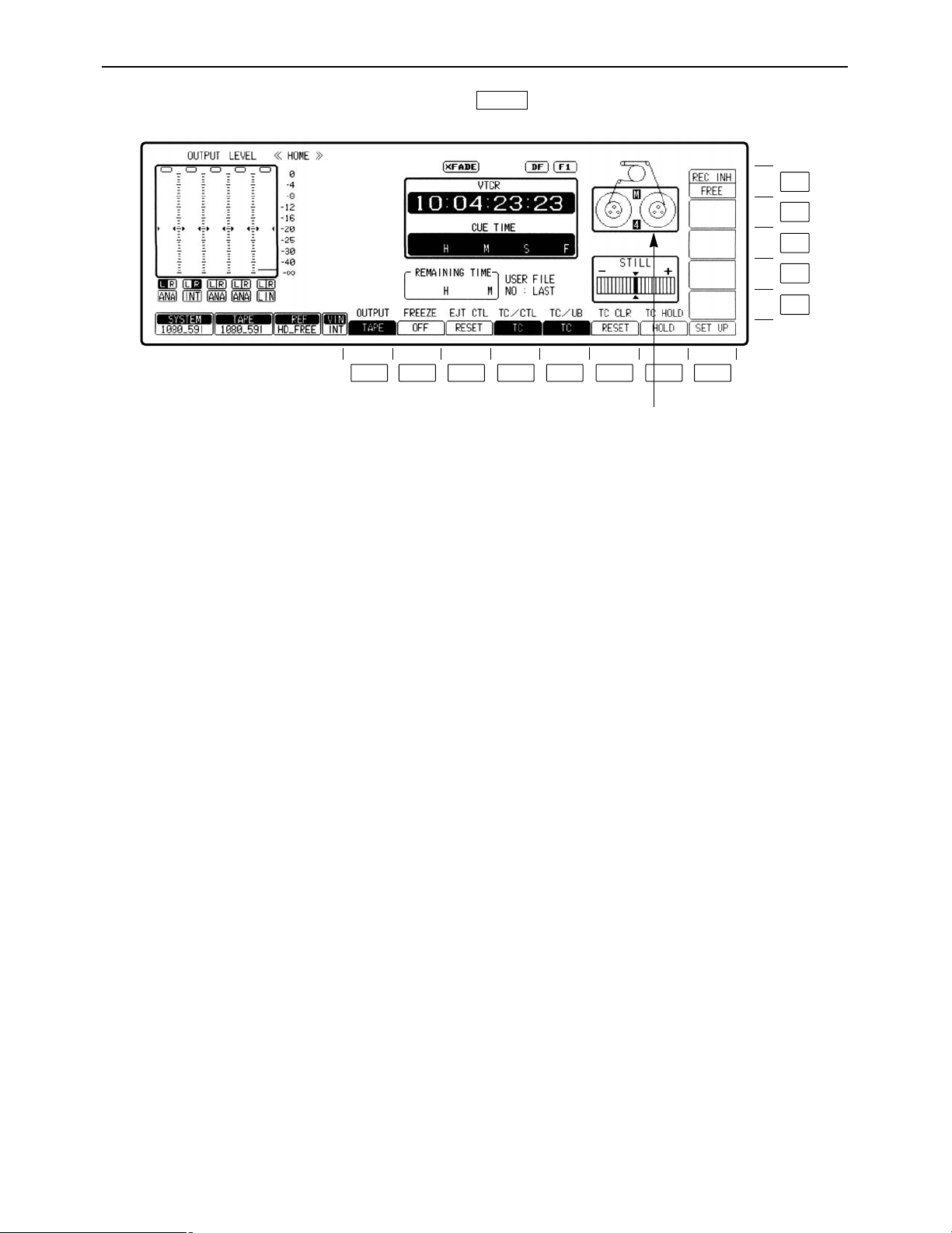
This menu is displayed by pressing the following key:
HOME
[4]: Cassette tape in the 4-channel audio format.
[8]: Cassette tape in the 8-channel audio format.
(This display indicates the C bit pin position of the
cassette tape.)
If system format does not matched with the C bit pin
position of the cassette tape, 4 or 8 display will flash
to warn its miss-matching.
– 13 –
Page 14

– 14 –
HOME menu
Key
F1
F2
F3
F4
F5
F6
F7
Key designation
OUTPUT
For selecting the
audio/video output signals.
FREEZE
For outputtting the flash
freeze frame.
EJT CTL
For CTL operation in
EJECT mode.
TC/CTL
For timer mode switching.
TC/UB
For switching the display
between the TC and UB
values.
TC CLR
For clearing the TC value.
(TCG CLR)
For clearing the UBG
value.
(UB CLR)
For clearing the UB value.
TC HOLD
For holding the TC value
on the display.
Description
The mode opposite to the current one is established only while
this key is held down. (When the key is pressed during TAPE
setting, the EE mode is established.)
(If this key is pressed together with the F key, the display
switches.)
TAPE: Outputs playback signal.
EE: Outputs the EE system signals.
≥Valid only in STOP, REC or EJECT mode. Invalid during
playback.
≥This key does not operate during CUE signal output.
Outputs field memory 1 screen continuously.
Flash freeze frame is assumed only while this key is pressed.
If this key is pressed together with the F key, the setting can be
fixed.
ON: Output field memory screens.
OFF: No freeze-framing.
RESET: Resets CTL1 when cassette is ejected. Resets CTL2
when cassette is loaded.
HOLD: Holds CTL values for both CTL1 and CTL2 when
cassette is ejected.
TC: Displays the time code.
CTL1: Displays the control signal value. (This can be reset to
zero.)
CTL2: Automatically resets the control signal value to zero
when the cassette tape is loaded. The control signal
value cannot be reset after this.
TC: Displays the TC value.
UB: Displays the UB value.
≥Valid only when [TC] is selected with F4 key.
≥Displays the time code readout value during playback.
≥Displays the time code value recorded on tape during
recording.
≥To display values generated at times other than recording,
press the INPUT CHECK key.
Valid only when the TC/CTL key is set to CTL1.
RESET: CTL1 time data is reset to zero.
Valid only when the TC/CTL key and the TC/UB key are set to TC.
RESET: TCG value is reset to zero when F key is
simultaneously pressed.
Valid only when the TC/CTL key is set to TC and the TC/UB key
is set to UB.
RESET: UBG value is reset to zero when F key is
simultaneously pressed.
However, since there are two UBG values, VITC UBG and LTC
UBG, they are supported as follows by the TCR settings on the
TC/CHR menu.
TCR: AUTO Both VITC UBG and LTC UBG are reset to zero.
TCR: LTC LTC UBG is reset to zero.
TCR: VITC VITC UBG is reset to zero.
Continues to display the time code data which was displayed
when the key was pressed.
≥Press again to release the hold value.
Page 15

– 15 –
HOME menu
Key
F8
F9–F10
F11
F12
F13
Key designation
SET UP
——
PREAD A°
For setting audio pre-read
to ON or OFF
(SD mode only)
PREAD V°
For setting video pre-read
to ON or OFF
(SD mode only).
REC INH
For setting the record
inhibit mode.
Description
Transfers the VTR to the HOME SET UP menu screen.
This is used during insert editing in the AUTO or MANUAL EDIT
mode when the already recorded digital signals are to be read in
advance and used as the editing source. To set the item to ON,
press the F together with the F11 or F12 key. To set it to OFF,
press the F11 or F12 key on its own. When ON is selected as
the setting, refer to the section on pre-read editing (next page).
ON: The digital signals are read in advance (pre-read).
OFF: The digital signals are not read in advance (pre-read).
Simultaneous playback is possible during editing.
≥If OFF is selected by the F11 or F12 key, vibration may occur
when EE has been selected on the STATE screen. (This
happens only when the input and output of the same channel
have been connected.)
≥If ON has been set for either of these items, the up-converter
picture will be muted.
FREE: Enables recording.
NRML.REC: Prohibits normal recording; enables editing. (The
REC INHIBIT lamp blinks at long intervals.)
ALL: Prohibits all recording. (REC INHIBIT lamp
glows.)
≥The CASSETTE REC INHIBIT mode which is set using the
recording inhibit pins on the cassette tape takes precedence
over this key’s setting.
°The above functions can be set only when the 480/59.94i system format is selected.
Page 16
– 16 –
HOME menu
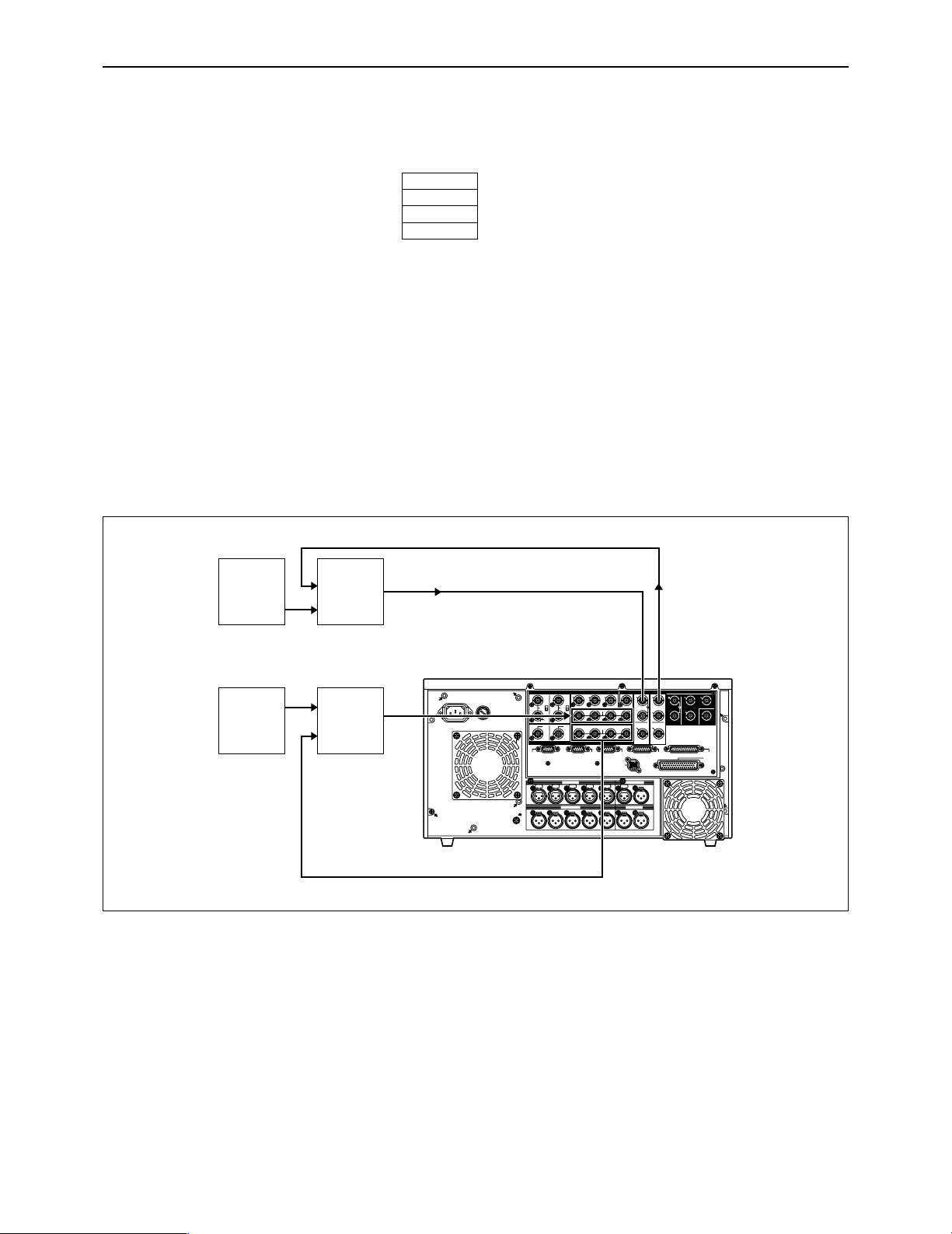
∑ Pre-read editing
(1) Set the pre-read function to ON by pressing the F key and F11 key (PREAD A) or F12 key
(PREAD V) together.
(2) Perform the connections for pre-read editing as shown in the figure below.
(3) Proceed with pre-read editing in the desired insert editing mode.
(4) Restore the original connections upon completion of the editing.
(5) Press the F11 or F12 key to set the pre-read function to OFF.
(6) Check that there are no loop connections.
ONoteN
During pre-read operations, the SD SDI MONITOR and AUDIO MONITOR connectors function
as monitoring connectors, and the input signals are output from the IN point to the OUT point in
their original state.
Further, the preread monitor function will not work when the monitor MIX function has been set
to ON. To use the function, set MIX to OFF.
PREAD V
ON
PREAD A
ON
Connections for pre-read editing
~
AC IN
CH 1 CH 2 CH 3 CH 4 CUE L R
H 1
SIGNAL
GND
PUSH
H 2
PUSH
H 3
PUSH
H 4
PUSH
H 5
PUSHNPUSH
OUT
OUTPUT
CH CH CH CH
INPUT
CH CH CH CH
HD
HD
REMOTE
IN
ON
OFF
123
(
SUPER
)
(
SUPER
)
IN
IN
OUT
HD SDISD SDIWFMVIDEO OUTREF IN
REF OUT DIGITAL AUDIO
1
OUT1
OUT2
OUT
2
OUT
3
MONITOR
MONITOR
(
SUPER
)
SPARE
ACTIVE
THROUGH
REMOTE
OUT
REMOTE
IN/OUT
CONTROL
PANEL
V/A
CONTROL
RS-232C
PA
RALLEL
IN/OUT
(
50P
)
SD
SD
SD
ON
OFF
FUSE
125V 5A
AUDIO OUT
AUDIO IN
MONITOR
TIME CODE
ACTIVE
THROUGH
75Ω75
Ω
3
4
π
1
2
π
7
8
π
5
6
π
7
8
π
5
6
π
3
4
π
1
2
π
Video
Source
Video
Switcher
Audio
Source
Audio
Mixer
Digital video output
Digital video input
SD SDI OUTSD SDI IN
Digital
or
analog
audio
input
Digital or analog audio output
Page 17
– 17 –
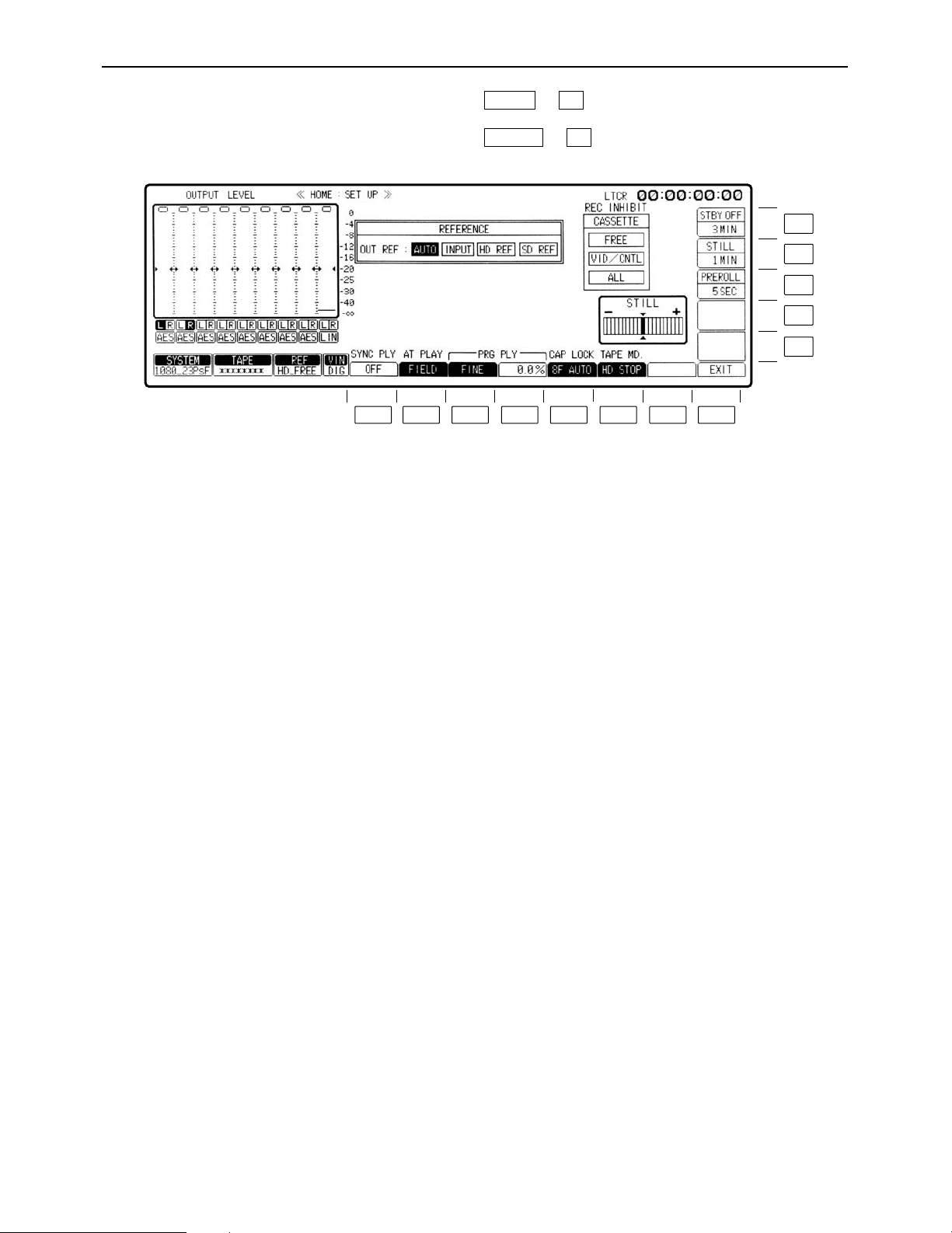
HOME SET UP menu
This menu is displayed by pressing the following keys: )
OR
)
F1SET UP
F8HOME
F13
F12
F11
F10
F9
F8F7F6F5F4F3F2F1
Page 18

– 18 –
HOME SET UP menu
Key
F1
F2
F3
F4
F5
F6
F7
F8
Key designation
SYNC PLY
Sync play.
AT PLY
For switching the playback
picture in JOG/VAR.
PRG PLAY
Program play.
PRG PLAY
Program play.
CAP LOCK°
3
For setting the capstan
servo lock
TAPE MD.
Tape mode when the VTR
is in standby OFF.
——
EXIT
Description
Automatically compensates for the start initiated for the playback
mode. For instance, when the VTR is set to the playback mode
from the preroll point, it synchronizes its own phase to ensure
that the tape arrives at the IN point after the preroll time has
elapsed. (The function takes effect only when the front panel
controls are used for operation.)
ON: Sync play function operates.
OFF: Normal playback is assumed.
FIELD: Plays the tape field by field.
FRAME1°1/
FRAME2°2: Plays back on a frame by frame basis at the j1a to
i1a speed and on a field by field basis at all other
speeds. If the tape material image has a scene
cutoff when moving from No. 2 field to No. 1 field,
as when editing with the No. 1 field as cutoff, use
FRAME 1.
Use Frame 2 when the No. 2 field is the scene
cutoff.
Selects the variable step for program play.
FINE: 0.1% step
COARSE: 1.0% step
Normal playback occurs at variable speed within the range of
n5% with the variable step of the F3 key.
Refer to “Programmed play function”.
Selects the capstan servo lock mode during playback.
4F AUTO (8F AUTO: 1080/23p, 1080/24p, 1080/50i):
Assumes color frame auto lock mode. If there is any discontinuity
in the color frame during playback, the unit locks again at a new
color frame.
4F FORCE (8F FORCE: 1080/23p, 1080/24p, 1080/50i):
Assumes color frame forced lock mode. If there is any
discontinuity in the color frame during playback, the unit
preserves the field sequence at initial lock.
2F: Assumes frame lock mode.
≥The capstan servo lock mode can be set in AUTO (or
MANUAL) EDIT SET UP menu. If the two settings differ, priority
is given to the final mode setting.
HD.STOP: Stops the drum when the tape is loose.
HLF LOAD: Half-loads the tape.
Returns the VTR to the HOME menu screen.
°1This item is not displayed when the 720/59p mode has been selected.
°
2
This item does not funtion when the 720/59p, 1080/23Psf or 1080/24Psf mode has been selected.
°
3
ONoteN
In the 1080/59i mode, the factory setting for this item is 2F. In the 1080/23p mode, it is 8F AUTO. The fact that the factory
setting differs depending on the format should be borne in mind when one format is converted into another.
Page 19

– 19 –
HOME SET UP menu
Key
F9–F10
F11
F12
F13
Key designation
——
PREROLL
For selecting the preroll
time.
STILL
For setting the
STOP/STILL (static frame)
mode holding time.
STBY OFF
For setting the time for the
transfer to standbay OFF.
Description
After pressing the F11 key, turn the ADJUST control.
Selection can be made between 0 and 30 seconds.
Sets the stop/still (still picture) mode holding time.
In order to protect the tape, the VTR is automatically transferred
to the tape tension release mode (loosing) after a specific time
has elapsed. This specific time can be set.
After pressing the F12 key, turn the ADJUST control.
1 sec, 3 sec, 30 sec, 1 min, 3 min or 5 min can be set as the
holding time.
For setting the time for the transfer from tape loosing to standby
OFF.
After pressing the F13 key, turn the ADJUST control.
1 sec, 3 sec, 30 sec, 1 min, 3 min, 16 min and ¶ [Infinity: No
transfer to standby OFF mode (drum stop/half loading)] can be
set.
Page 20
– 20 –
HOME SET UP menu
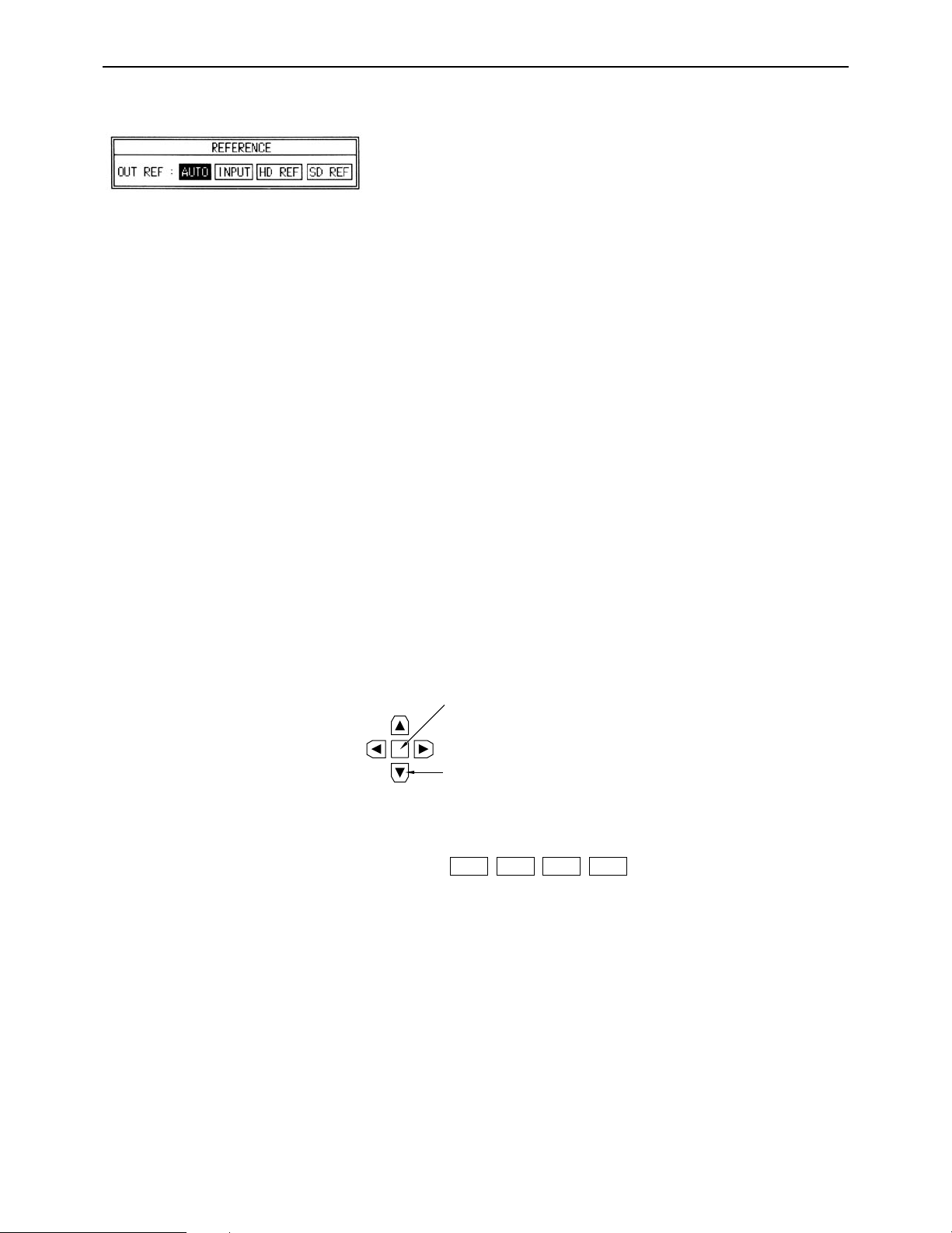
∑ Reference
OUT REF: This sets the video output signal reference.
AUTO: When the REF VIDEO connector input sig-
nal is available, the output reference is
locked to REF VIDEO; when it is not available, it is locked to the INPUT input signal.
When neither the REF VIDEO nor INPUT
input signal is available, the internal signal
serves as the reference.
Depending on the format, the sequence of
priority is as follows:
HD mode:
HD REFNSD REFNINPUTNFREE
SD mode:
SD REFNHD REFNINPUTNFREE
INPUT: When the INPUT input signal is available,
the output reference is locked to the INPUT
signal; when it is not available, the internal
signal serves as the reference.
HD REF: When the HD REF input signal is available
at the HD REF IN connector, the output reference is locked to the REF signal; when it
is not available, the internal signal serves as
the reference.
SD REF: When the SD REF input signal is available
at the SD REF IN connector, the output reference is locked to the REF signal; when it
is not available, the internal signal serves as
the reference.
Operation
(1) Press the center cursor key.
The cursor now appears.
(2) Move the cursor to the item to be set using the cursor keys.
The selected item now blinks.
(3) Press the ENT key. The setting is now entered.
°In the 720/59p mode, use the SD REF for synchronization with an external component. (In this mode, SD REF or
SF FREE is used.)
°When AUTO has been set, the sequence of priority is as follows: SD REFNFREE.
Center cursor key
Cursor key
OUT REF:
INPUT
Page 21

– 21 –
HOME SET UP menu
∑ Programmed play function
(1) Press the F4 (PRG PLY) key.
(2) Set the step to FINE or COARSE using the F3 (PRG PLY) key.
(3) Set the programmed play speed using the ADJUST control.
(4) Press the PLAY and VAR buttons together.
(5) To change the playback speed, turn the ADJUST control while pressing the VAR button.
(6) To stop programmed play, press the STOP button.
2.0%
PRG PLY
Page 22
– 22 –
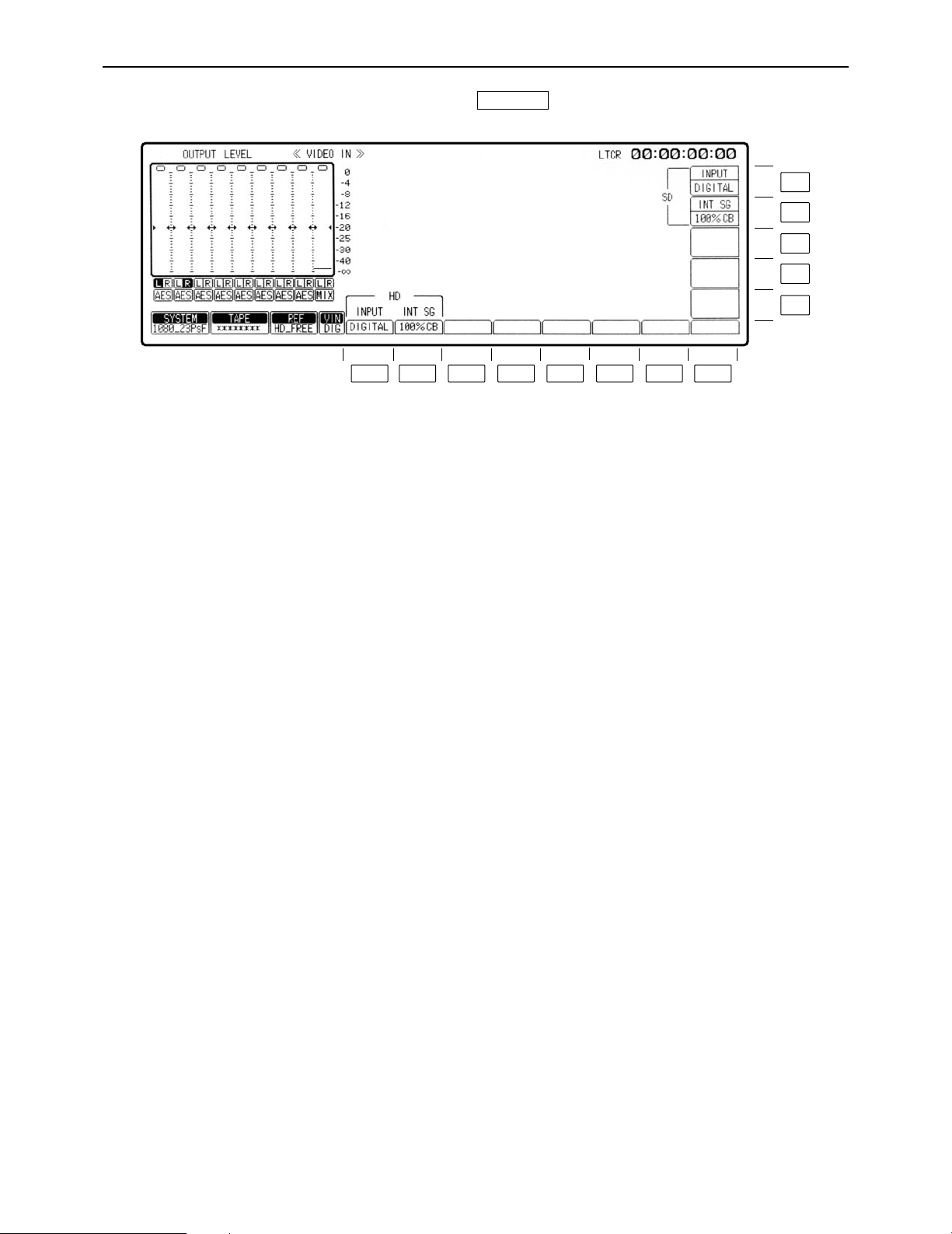
VIDEO IN menu
This menu is displayed by pressing the following key:
VIDEO IN
F13
F12
F11
F10
F9
F8F7F6F5F4F3F2F1
Page 23

– 23 –
VIDEO IN menu
Key
F1
F2
F3–F11
F12
F13
Key designation
INPUT
For selecting the HD video
input signals.
INT SG
For selecting the type of
HD internal signals.
——
INT SG
For selecting the type of
SD internal signals.
INPUT
For selecting the SD video
input signals.
Description
DIGITAL: Selects the serial input signals.
INT SG: Selects the internal signals.
75% CB: Selects the 75% color bar signal.
100% CB: Selects the 100% color bar signal.
RAMP: Selects the RAMP signal.
MULT-BST: Selects the multi-burst signal.
BLACK: Selects the black-burst signal.
SIF PLL: Selects the signals for checking the serial
interface PLL.
SIF EQ: Selects the signal for checking the serial interface
equalizer.
SMPTE CB°: Selects the SMPTE color bar signal.
DIGITAL: Selects the serial input signals.
INT SG: Selects the internal signals.
°When the 720/59p format has been selected, the SMPTE CB function does not function
Page 24
– 24 –
VIDEO OUT HD menu
This menu is displayed by pressing the following key:
VIDEO OUT
F13
F12
F11
F10
F9
F8F7F6F5F4F3F2F1
Page 25

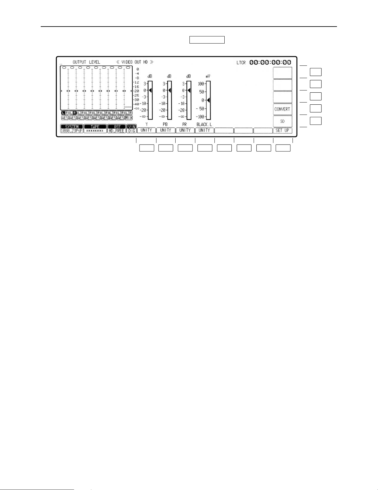
– 25 –
VIDEO OUT HD menu
Key
F1
F2
F3
F4
F5– F7
F8
F9
F10
F11– F13
Key designation
For adjusting the Y level.
PB
For adjusting the PB level.
PR
For adjusting the PR
level.
BLACK.L
For adjusting the black
level.
——
SET UP
SD
CONVERT
——
Description
j¶ to i3 dB (j3 dB to i3 dB in fine adjustment mode)
≥Establishes the fine adjustment mode if the key is pressed
together with the F key.
j¶ to i3 dB (j3 dB to i3 dB in fine adjustment mode)
≥Establishes the fine adjustment mode if the key is pressed
together with the F key.
j¶ to i3 dB (j3 dB to i3 dB in fine adjustment mode)
≥Establishes the fine adjustment mode if the key is pressed
together with the F key.
n100 mV
Transfers the VTR to the VIDEO OUT HD SET UP menu screen.
Transfers the VTR to the VIDEO OUT SD menu screen.
Transfers the VTR to the VIDEO OUT CONVERT menu screen.
Page 26
– 26 –
VIDEO OUT HD SET UP menu
This menu is displayed by pressing the following keys: >
F8VIDEO OUT
F13
F12
F11
F10
F9
F8F7F6F5F4F3F2F1
Page 27

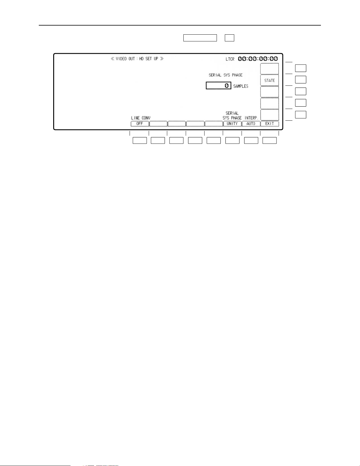
– 27 –
VIDEO OUT HD SET UP menu
Key
F1
F2– 5
F6
F7
F8
F9– F11
F12
F13
Key designation
LINE CONV°
——
SERIAL SYS PHASE
INTERP.
Interpolation
EXIT
——
STATE
——
Description
Line conversion function
OFF: No line conversion; when a 1035 tape is played back,
1080 signals with black bands added at the top and
bottom of the picture are output.
ON: Conversion from 1035 to 1080 lines.
Assumes white-on-black display (VAR mode) when the F key
and F6 key are pressed simultaneously, and can be adjusted
with the ADJUST control. Adjustment is possible up to a
maximum of n0.5 H (depending on the mode).
w1375 SAMPLE: 1080/23p and 1080/24p formats
w1320 SAMPLE: 1080/50i and 1080/25p formats
w1100 SAMPLE: 1080/59i format
w825 SAMPLE: 720/59p format
(1_SAMPLEl13.5 nSEC)
Adjustment is by sample increments.
Initiates vertical interpolation during AT playback to reduce the
vertical movement of the playback images.
AUTO: Automatically initiates interpolation in the JOG or VAR
mode.
OFF: No interpolation.
Returns the VTR to the VIDEO OUT HD menu screen.
Transfers the VTR to the VIDEO OUT HD SET UP STATE menu
screen.
°This item only functions when the 1080/59i format has been selected.
Page 28
– 28 –
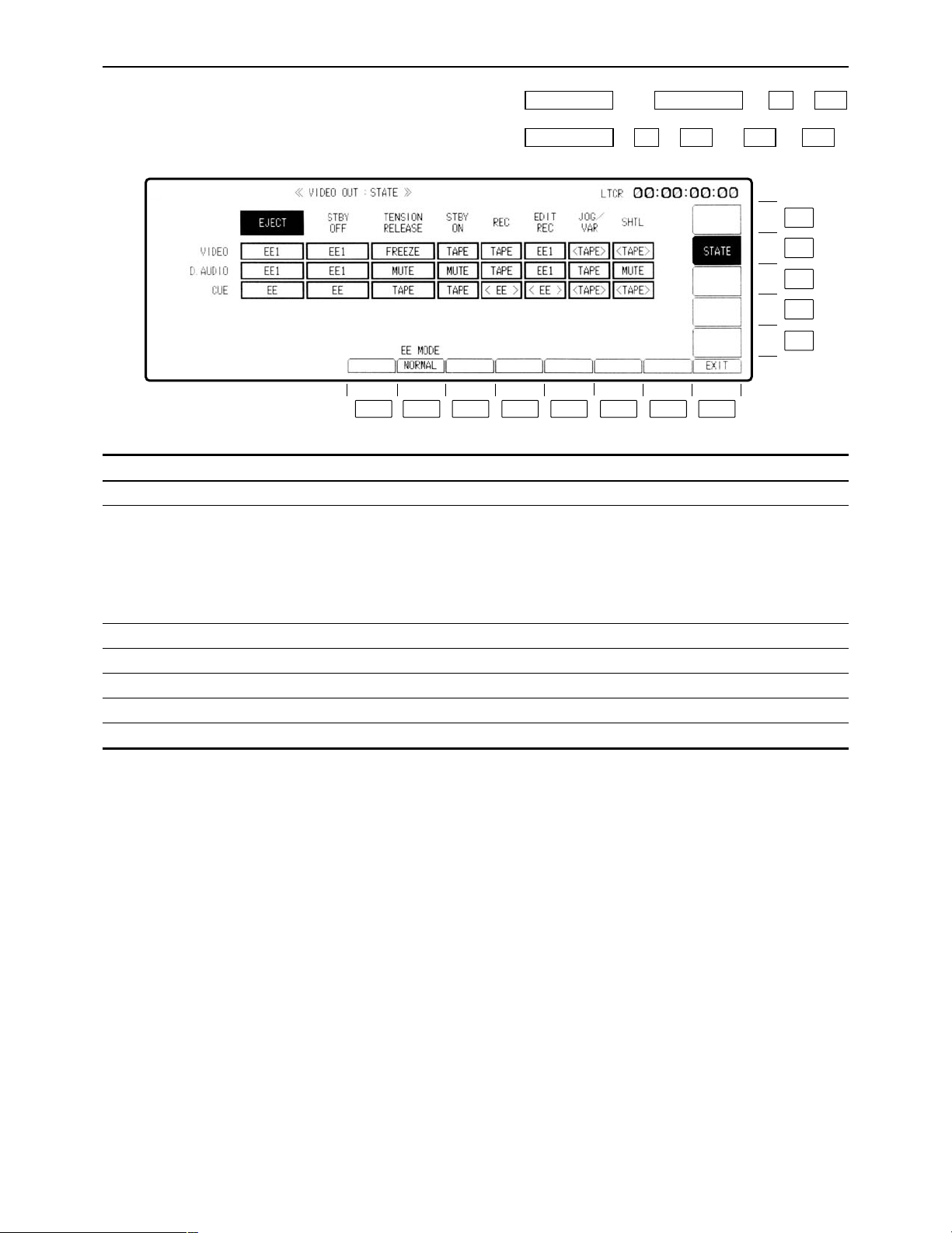
VIDEO OUT HD SET UP STATE menu
This menu is displayed by pressing the following keys: (or )>>
OR
>> (or )>
F12F12F11F9VIDEO OUT
F12F8AUDIO OUTVIDEO OUT
Description
NORMAL: The standard mode is established (E-E through
mode is turned OFF).
THROUGH: When the EE/EE1 is selected, the E-E through
mode (AV minimum delay mode) is established.
°A discrepancy occurs between the video (audio) output and time
code output in the E-E through mode.
Transfers the VTR to the VIDEO OUT HD SET UP menu screen.
Transfers the VTR to the VIDEO OUT HD SET UP menu screen.
Key
F1
F2
F3– F7
F8
F9– F11
F12
F13
Key designation
——
EE_MODE
——
EXIT
——
STATE
——
F13
F12
F11
F10
F9
F8F7F6F5F4F3F2F1
Page 29
– 29 –
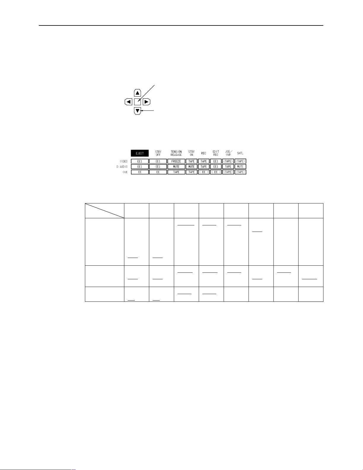
VIDEO OUT SET UP STATE menu
∑ Selecting the TAPE/EE output signals
The video, audio and cue signals which are output during the VTR’s operation are switched on
this menu to TAPE or EE signals.
(1) Press the center cursor key to display the cursor.
(2) Move the cursor to the desired position using the cursor keys.
°The cursor will not move to places which cannot be set.
(3) Press the center cursor key to select TAPE or EE.
Refer to the following table for the types of setting options.
Center cursor key
Cursor key
≥When a setting is to be established during head selection using the TEST menu or during edit-
ing, the setting applying to the operation concerned takes precedence over the setting selected using the VIDEO OUT SET UP STATE menu.
≥When TAPE/EE has been set by F1 (OUTPUT) on the HOME menu, the HOME menu setting
takes precedence.
(Underline denotes the factory setting mode.)
Mode
CH
VIDEO
D.AUDIO
CUE
EJECT
FREEZE
BLACK
GRAY
FREE
NOISE
EE1
EE2
MUTE
EE1
EE2
TAPE
EE
STBY
OFF
FREEZE
BLACK
GRAY
FREE
NOISE
EE1
EE2
MUTE
EE1
EE2
TAPE
EE
TENSION
RELEASE
FREEZE
BLACK
GRAY
FREE
NOISE
EE1
EE2
MUTE
EE1
EE2
TAPE
EE
STBY
ON
TAPE
EE1
EE2
MUTE
EE1
EE2
TAPE
EE
REC
TAPE
EE1
EE2
TAPE
EE1
EE2
EE
EDIT
REC
TAPE
EE1
TAPE
EE1
EE
JOG/
VAR
TAPE
TAPE
MUTE
TAPE
SHTL
TAPE
TAPE
MUTE
TAPE
Page 30
– 30 –
VIDEO OUT SD menu
This menu is displayed by pressing the following keys: >
F9VIDEO OUT
F13
F12
F11
F10
F9
F8F7F6F5F4F3F2F1
Page 31

– 31 –
VIDEO OUT SD menu
Key
F1
F2
F3
F4
F5– F6
F7
F8– F9
F10
F11
F12
F13
Key designation
Y
For adjusting the Y level.
PB
For adjusting the P
B level.
PR
For adjusting the PR
level.
BLACK.L
For adjusting the black
level.
——
HD
——
CONVERT
CMPST
SDI
——
Description
j¶ to i3 dB (j3 dB to i3 dB in fine adjustment mode)
≥Establishes the fine adjustment mode if the key is pressed
together with the F key.
j¶ to i3 dB (j3 dB to i3 dB in fine adjustment mode)
≥Establishes the fine adjustment mode if the key is pressed
together with the F key.
j¶ to i3 dB (j3 dB to i3 dB in fine adjustment mode)
≥Establishes the fine adjustment mode if the key is pressed
together with the F key.
n100 mV
Transfers the VTR to the VIDEO OUT HD menu screen.
Transfers the VTR to the VIDEO OUT CONVERT menu screen.
Transfers the VTR to the VIDEO OUT SD SET UP COMPOSITE
menu screen.
Transfers the VTR to the VIDEO OUT SD SET UP SDI menu
screen.
Page 32

– 32 –
VIDEO OUT SD SET UP COMPOSITE menu
This menu is displayed by pressing the following keys: >>
F11F9VIDEO OUT
F13
F12
F11
F10
F9
F8F7F6F5F4F3F2F1
Page 33

– 33 –
VIDEO OUT SD SET UP COMPOSITE menu
Key
F1
F2– F4
F5
F6
F7
F8
F9
F10
F11
F12
F13
Key designation
COMB FIL°
1
For controlling the comb
filter.
——
SYS SC
For adjusting the system
subcarrier.
SYS H
For adjusting the system H
phase.
INTERP.
Interpolation
EXIT
——
7.5%STUP
For adding 7.5% setup to
the composite output.
LINE BLK°
2
STATE
——
Description
Selects whether the analog composite output signals are to be
passed through the comb filter.
ON: The signals are passed through the filter and output.
OFF: The signals are not passed through the filter.
Adjusts the system subcarrier of the composite output.
When this key is pressed together with the F key, the white-onblack display (VAR MODE) is established, and the system
subcarrier can be adjusted using the ADJUST control.
Adjusts the system H phase of the composite output.
Adjusts the system H phase of the composite output.
When this key is pressed together with the F key, the white-onblack display (VAR MODE) is established, and the system H
phase can be adjusted using the ADJUST control.
The system H phase is adjusted in sample increments. n0.5H
j858 to i858 (with 480/59.94i format)
j864 to i864 (with 576/50i format)
Initiates vertical interpolation during AT playback to reduce the
vertical movement of the playback images.
AUTO: Automatically initiates interpolation in the JOG or VAR
mode.
OFF: No interpolation.
Returns the VTR to the VIDEO OUT SD menu screen.
Selects whether to add 7.5% setup to the composite output.
(This setting takes effect with NTSC output signals only; This
setting is not displayed with PAL output signals.)
ON: 7.5% setup is added.
OFF: 7.5% setup is not added.
For transferring to the video output line blanking menu.
NTSC: Lines 10 to 21.
PAL: Lines 8 to 22.
Transfers the VTR to the VIDEO OUT SD SET UP CMPST
STATE menu screen.
°1This item does not function in the 1080/50i mode.
°
2
In a mode other than the 525i (480/59i) mode, this adjustment is possible only when the AJ-UDC3700P HD-SD
format converter board (optional accessory) has been installed.
Page 34

– 34 –
VIDEO OUT SD SET UP CMPST STATE menu
This menu is displayed by pressing the following keys: (or [AUDIO OUT])>>
OR
>> (or )>
F12F12F11F9VIDEO OUT
F12F8VIDEO OUT
Description
NORMAL: The standard mode is established (E-E through
mode is turned OFF).
THROUGH: The E-E through mode (AV minimum delay mode)
is established.
°A discrepancy occurs between the video (audio) output and time
code output in the E-E through mode.
Transfers the VTR to the VIDEO OUT SD SET UP CMPST
menu screen.
Key
F1
F2
F3– F7
F8
F9– F13
Key designation
——
EE_MODE
——
EXIT
——
F13
F12
F11
F10
F9
F8F7F6F5F4F3F2F1
Page 35

– 35 –
VIDEO OUT SD SET UP CMPST STATE menu
∑ Selecting the TAPE/EE output signals
The video, audio and cue signals which are output during the VTR’s operation are switched on
this menu to TAPE or EE signals.
(1) Press the center cursor key to display the cursor.
(2) Move the cursor to the desired position using the cursor keys.
°The cursor will not move to places which cannot be set.
(3) Press the center cursor key to select TAPE or EE.
Refer to the following table for the types of setting options.
Center cursor key
Cursor key
≥When a setting is to be established during head selection using the TEST menu or during edit-
ing, the setting applying to the operation concerned takes precedence over the setting selected using the VIDEO OUT SET UP STATE menu.
≥When TAPE/EE has been set by F1 (OUTPUT) on the HOME menu, the HOME menu setting
takes precedence.
(Underline denotes the factory setting mode.)
Mode
CH
VIDEO
D.AUDIO
CUE
EJECT
FREEZE
BLACK
GRAY
FREE
NOISE
EE1
EE2
MUTE
EE1
EE2
TAPE
EE
STBY
OFF
FREEZE
BLACK
GRAY
FREE
NOISE
EE1
EE2
MUTE
EE1
EE2
TAPE
EE
TENSION
RELEASE
FREEZE
BLACK
GRAY
FREE
NOISE
EE1
EE2
MUTE
EE1
EE2
TAPE
EE
STBY
ON
TAPE
EE1
EE2
MUTE
EE1
EE2
TAPE
EE
REC
TAPE
EE1
EE2
TAPE
EE1
EE2
EE
EDIT
REC
TAPE
EE1
TAPE
EE1
EE
JOG/
VAR
TAPE
TAPE
MUTE
TAPE
SHTL
TAPE
TAPE
MUTE
TAPE
Page 36

– 36 –
VIDEO OUT SD SET UP SDI menu
This menu is displayed by pressing the following keys: ))
F12F9VIDEO OUT
F13
F12
F11
F10
F9
F8F7F6F5F4F3F2F1
Page 37

– 37 –
VIDEO OUT SD SET UP SDI menu
°1This adjustment is possible only when the AJ-UDC3700P HD-SD format converter board (optional accessory)
has been installed.
°
2
In a mode other than the 525i (480/59i) mode, this adjustment is possible only when the AJ-UDC3700P HD-SD
format converter board (optional accessory) has been installed.
Key
F1– F4
F5
F6
F7
F8
F9– F10
F11
F12
F13
Key designation
——
SERIAL SYS PHASE
INTERP.
Interpolation
EXIT
——
LINE BLK°
2
STATE
——
Description
Adjusts the sync phase of SD_SDI output in relation to the
reference signal.
FINE/COARSE
≥This can be selected when the function key is pressed together
with the F key.
With the 480/59.94i format: Adjustment can be made from
j2H-858 to i1Hi858.
With the 480/59.94p format°1: Adjustment can be made from
j857 to +858.
With the 576/50i format°1: Adjustment can be made from
j2H-864 to i1Hi864.
For FINE, adjustments are made in sample increments; for
COARSE, they are made in H increments.
Initiates vertical interpolation during AT playback to reduce the
vertical movement of the playback images.
AUTO: Automatically initiates interpolation in the JOG or VAR
mode.
OFF: No interpolation.
Returns the VTR to the VIDEO OUT SD menu screen.
For transferring to the video output line blanking menu.
NTSC: Lines 10 to 21.
PAL: Lines 8 to 22.
Transfers the VTR to the VIDEO OUT SD SET UP SDI STATE
menu screen.
Page 38
– 38 –
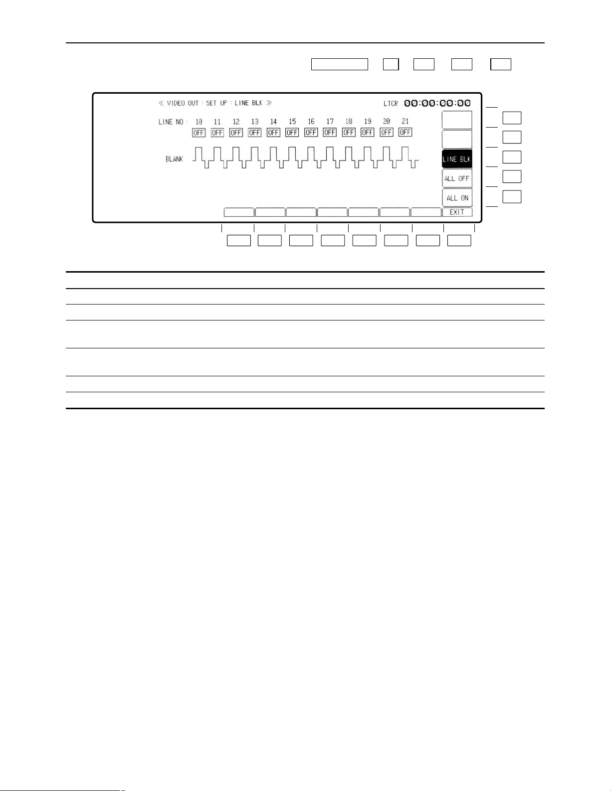
VIDEO OUT SET UP LINE BLK (video output line blanking) menu
This menu is displayed by pressing the following keys: )) (or ) ) .
F11F12F11F9VIDEO OUT
Key
F1– F7
F8
F9
F10
F11
F12– F13
Key designation
——
EXIT
ALL ON
ALL OFF
LINE BLK
——
Description
Returns the VTR to the VIDEO OUT SD SET UP menu screen.
When this key is pressed together with the F key, all the lines are
blanked.
When this key is pressed together with the F key, all the lines are
non-blanked.
Refer to the “Setting the line blanking” (on the next page).
F8F7F6F5F4F3F2F1
F13
F12
F11
F10
F9
Page 39

– 39 –
VIDEO OUT SET UP LINE BLK (video output line blanking) menu
∑ Setting the line blanking
The blanking lines in the vertical blanking period can be set in 1-line increments.
(1) Press the center cursor key.
The cursor now appears.
(2) Move the cursor and select the lines to be blanked.
(3) Press the center cursor key to select ON or OFF for the display.
ON: The lines are blanked.
OFF: The non-blanking status is established, and no lines are selected.
(4) Press the ENT key.
The blanking is now entered.
(5) To return to the previous screen, press the F8 (EXIT) key.
Center cursor key
Cursor key
OFF
ON
Page 40

– 40 –
VIDEO OUT SD SET UP SDI STATE menu
This menu is displayed by pressing the following keys: (or ) ))
OR
)) (or ) ) .
F12F12F11F9VIDEO OUT
F12F8AUDIO OUTVIDEO OUT
Key
F1
F2
F3
–
F7
F8
F9– F13
Key designation
——
EE_MODE
——
EXIT
——
Description
NORMAL: The standard mode is established (E-E through
mode is turned OFF).
THROUGH: The E-E through mode (AV minimum delay mode)
is established.
°A discrepancy occurs between the video (audio) output and time
code output in the E-E through mode.
Transfers the VTR to the VIDEO OUT SD SET UP SDI menu
screen.
F8F7F6F5F4F3F2F1
F13
F12
F11
F10
F9
Page 41

– 41 –
VIDEO OUT SET UP STATE menu
∑ Selecting the TAPE/EE output signals
The video, audio and cue signals which are output during the VTR’s operation are switched on
this menu to TAPE or EE signals.
(1) Press the center cursor key to display the cursor.
(2) Move the cursor to the desired position using the cursor keys.
°The cursor will not move to places which cannot be set.
(3) Press the center cursor key to select TAPE or EE.
Refer to the following table for the types of setting options.
Center cursor key
Cursor key
≥When a setting is to be established during head selection using the TEST menu or during edit-
ing, the setting applying to the operation concerned takes precedence over the setting selected using the VIDEO OUT SET UP STATE menu.
≥When TAPE/EE has been set by F1 (OUTPUT) on the HOME menu, the HOME menu setting
takes precedence.
(Underline denotes the factory setting mode.)
Mode
CH
VIDEO
D.AUDIO
CUE
EJECT
FREEZE
BLACK
GRAY
FREE
NOISE
EE1
EE2
MUTE
EE1
EE2
TAPE
EE
STBY
OFF
FREEZE
BLACK
GRAY
FREE
NOISE
EE1
EE2
MUTE
EE1
EE2
TAPE
EE
TENSION
RELEASE
FREEZE
BLACK
GRAY
FREE
NOISE
EE1
EE2
MUTE
EE1
EE2
TAPE
EE
STBY
ON
TAPE
EE1
EE2
MUTE
EE1
EE2
TAPE
EE
REC
TAPE
EE1
EE2
TAPE
EE1
EE2
EE
EDIT
REC
TAPE
EE1
TAPE
EE1
EE
JOG/
VAR
TAPE
TAPE
MUTE
TAPE
SHTL
TAPE
TAPE
MUTE
TAPE
Page 42

– 42 –
VIDEO OUT CONVERT menu
(This menu appears when the AJ-UDC3700P HD-SD format converter board, an optional accessory, has
been installed.)
This menu is displayed by pressing the following keys: )
F10VIDEO OUT
Key
F1
F2
F3
F4– F6
F7
F8
F9
F10– F1
3
Key designation
HD_TO_SD
SD_TO_HD
HD_TO_HD
——
HD
——
SD
——
Description
Transfers the VTR to the VIDEO OUT CONVERT HD TO SD
menu screen.
Transfers the VTR to the VIDEO OUT CONVERT SD TO HD
menu screen.
Transfers the VTR to the VIDEO OUT CONVERT HD TO HD
menu screen.
Returns the VTR to the VIDEO OUT HD menu screen.
Returns the VTR to the VIDEO OUT SD menu screen.
F13
F12
F11
F10
F9
F8F7F6F5F4F3F2F1
Page 43
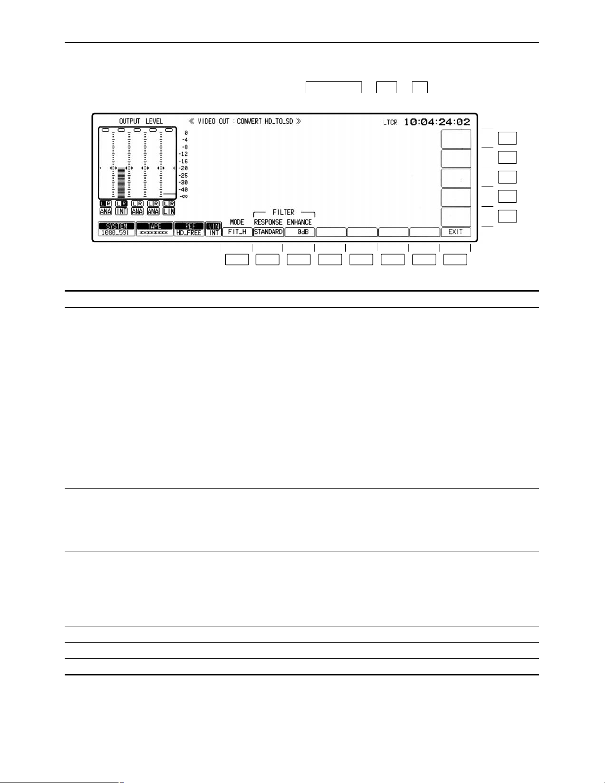
– 43 –
VIDEO OUT CONVERT HD_TO_SD menu
(This menu appears when the AJ-UDC3700P HD-SD format converter board, an optional accessory, has
been installed.)
This menu is displayed by pressing the following keys: ))
F1F10VIDEO OUT
Key
F1
F2
F3
F4–F7
F8
F9–F13
Key designation
MODE
RESPONSE
ENHANCE
——
EXIT
——
Description
Selects the aspect ratio at which signals are output from the
down-converter.
FIT_V: Changes the magnification by matching the input size
to the output size along the perpendicular axis. (The
aspect ratio remains the same.)
FIT_H: Changes the magnification by matching the input size
to the output size along the horizontal axis. (The
aspect ratio remains the same.)
FIT_HV: Changes the magnification by matching the input size
to the output size along the horizontal and
perpendicular axes. (The aspect ratio may be distorted.)
14:9: Sets the aspect ratio to 14k9.
13:9: Sets the aspect ratio to 13k9.
°When the 525p (480/59.94p) has been selected for the SD SDI
MAIN output, the aspect ratio remains fixed at 16:9.
Selects the frequency bandwidth of the down-converter output
signals.
STANDARD:
WIDE:
NARROW:
Controls the enhancement adjustment of the down-converter
output signals.
6dB:
3dB:
1.5dB:
0dB:
Returns the VTR to the VIDEO OUT CONVERT menu screen.
F13
F12
F11
F10
F9
F8F7F6F5F4F3F2F1
Page 44
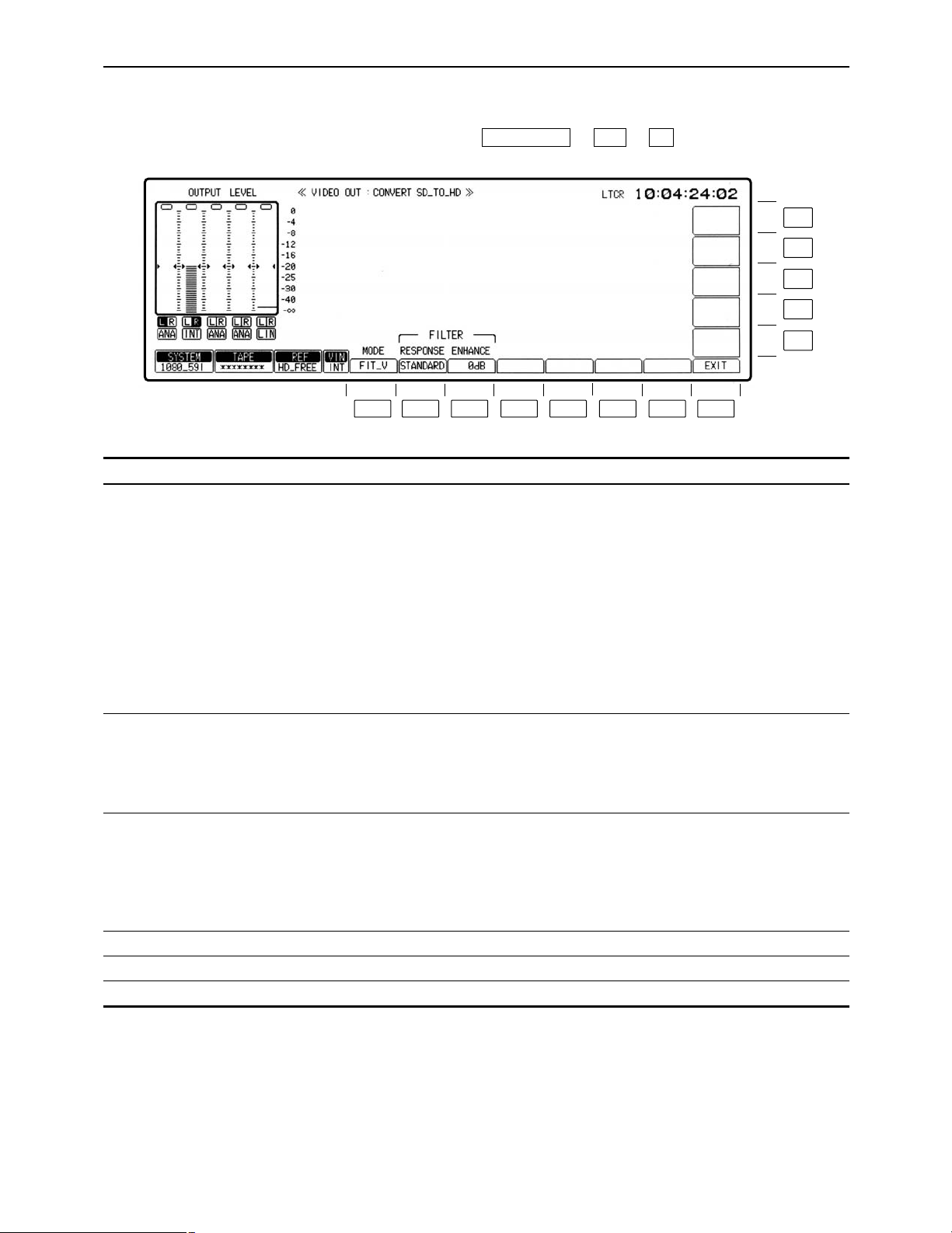
– 44 –
VIDEO OUT CONVERT SD_TO_HD menu
(This menu appears when the AJ-UDC3700P HD-SD format converter board, an optional accessory, has
been installed.)
This menu is displayed by pressing the following keys: ))
F2F10VIDEO OUT
Key
F1
F2
F3
F4– F7
F8
F9– F13
Key designation
MODE
RESPONSE
ENHANCE
——
EXIT
——
Description
Selects the aspect ratio at which signals are output from the upconverter.
FIT_V: Changes the magnification by matching the input size
to the output size along the perpendicular axis. (The
aspect ratio remains the same.)
FIT_H: Changes the magnification by matching the input size
to the output size along the horizontal axis. (The
aspect ratio remains the same.)
FIT_HV: Changes the magnification by matching the input size
to the output size along the horizontal and
perpendicular axes. (The aspect ratio may be
distorted.)
Selects the frequency bandwidth of the up-converter output
signals.
STANDARD:
WIDE:
NARROW:
Controls the enhancement adjustment of the up-converter output
signals.
6dB:
3dB:
1.5dB:
0dB:
Returns the VTR to the VIDEO OUT CONVERT menu screen.
F13
F12
F11
F10
F9
F8F7F6F5F4F3F2F1
Page 45
– 45 –
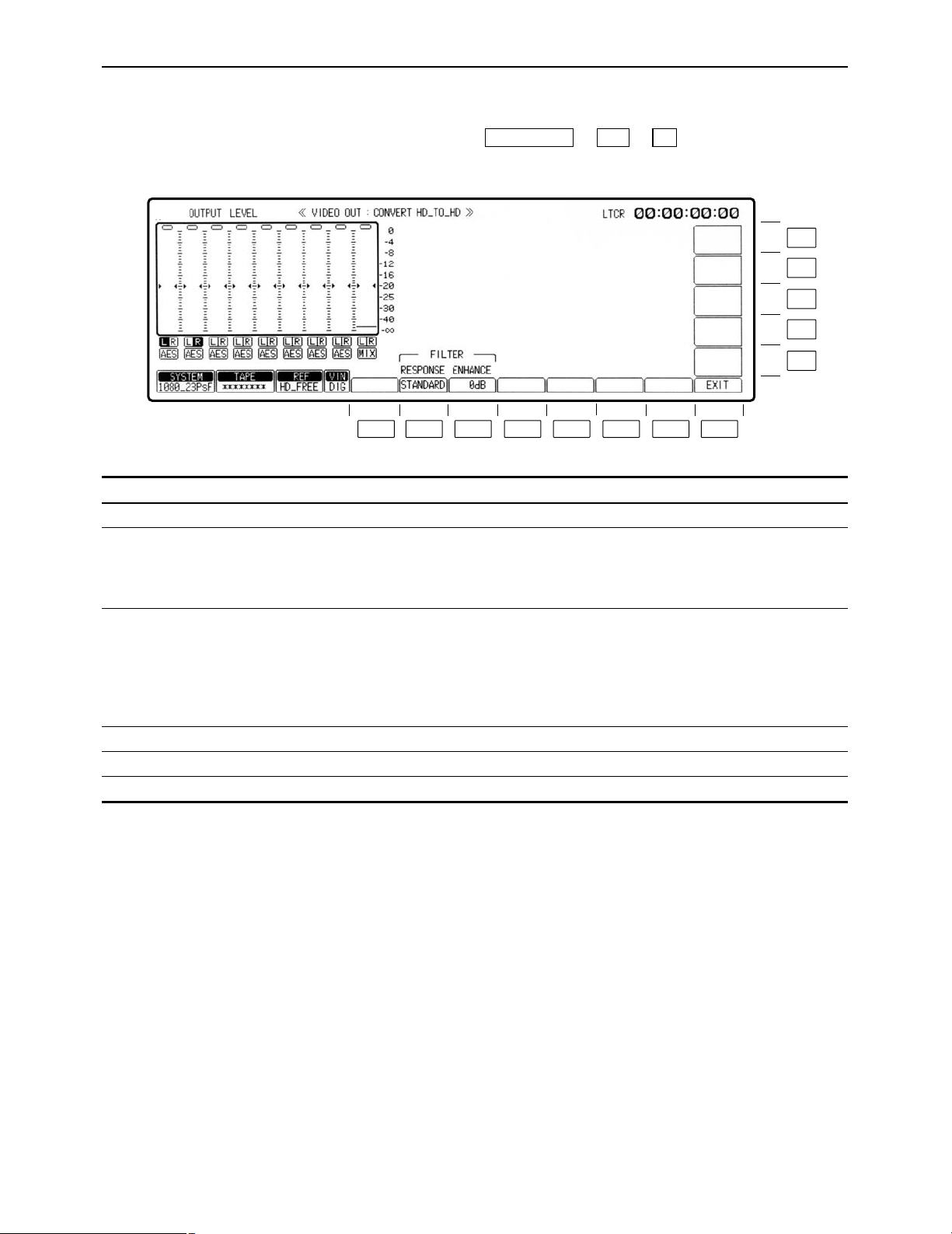
VIDEO OUT CONVERT HD_TO_HD menu
(This menu appears when the AJ-UDC3700P HD-SD format converter board, an optional accessory, has
been installed.)
This menu is displayed by pressing the following keys: ))
°This menu is operational when 1080/23.98p or 1080/24p has been set as the system format.
F3
F10VIDEO OUT
Key
F1
F2
F3
F4–F7
F8
F9–F13
Key designation
——
RESPONSE
ENHANCE
——
EXIT
——
Description
——
Selects the frequency bandwidth of the converter output signals.
STANDARD:
WIDE:
NARROW:
Controls the enhancement adjustment of the converter output
signals.
6dB:
3dB:
1.5dB:
0dB:
Returns the VTR to the VIDEO OUT CONVERT menu screen.
F13
F12
F11
F10
F9
F8F7F6F5F4F3F2F1
Page 46

– 46 –
AUDIO IN menu
This menu is displayed by pressing the following key:
AUDIO IN
The digital audio input statuses are displayed here.
PRE EMPHASIS ON: Pre-emphasis is applied to the input signals.
OFF: Regular signals with no pre-emphasis are
supplied.
F13
F12
F11
F10
F9
F8F7F6F5F4F3F2F1
Page 47

– 47 –
AUDIO IN menu
Key
F1
F2
F3
F4
F5
F6
F7
F8
F9
F10
F11
F12
F13
Key designation
CH-1
For adjusting the audio
CH1 input level.
CH-2
For adjusting the audio
CH2 input level.
CH-3
For adjusting the audio
CH3 input level.
CH-4
For adjusting the audio
CH4 input level.
CUE
For adjusting the cue
audio input level.
PCM
CUE
SET UP
CH-MIX
CH-5
For adjusting the audio
CH5 input level.
CH-6
For adjusting the audio
CH6 input level.
CH-7
For adjusting the audio
CH7 input level.
CH-8
For adjusting the audio
CH8 input level.
Description
UNITY: Input level is fixed at UNITY value.
VAR: Input level can be varied with ADJUST control.
≥For switchover, press the UNITY/VAR button.
Transfers the VTR to AUDIO IN PCM INPUT SELECT menu
screen.
Transfers the VTR to the AUDIO IN CUE INPUT menu screen.
Transfers the VTR to the AUDIO IN SET UP menu screen.
Transfers the VTR to the AUDIO IN CH-MIX menu screen.
UNITY: Input level is fixed at UNITY value.
VAR: Input level can be varied with ADJUST control.
≥For switchover, press the UNITY/VAR button.
Page 48

– 48 –
AUDIO IN PCM INPUT SELECT menu
This menu is displayed by pressing the following keys: >
F6AUDIO IN
F13
F12
F11
F10
F9
F8F7F6F5F4F3F2F1
Page 49

– 49 –
AUDIO IN PCM INPUT SELECT menu
Key
F1
F2
F3
F4
F5
F6
F7
F8
F9
Key designation
CH-1
For selecting the recording
signals of digital audio
CH1.
CH-2
For selecting the recording
signals of digital audio
CH2.
DIGITAL
For selecting the CH1 and
CH2 digital input signals.
CH-3
For selecting the recording
signals of digital audio
CH3.
CH-4
For selecting the recording
signals of digital audio
CH4.
DIGITAL
For selecting the CH3 and
CH4 digital input signals.
DIGITAL
For selecting the CH5 and
CH6 digital input signals.
EXIT
CH-5
For selecting the recording
signals of digital audio
CH5.
Description
ANALOG: Selects the signals of the analog CH1 input
connector.
DIGITAL: Selects the digital audio input signals (AES/SDI
selection is made in line with the CH2 setting using
F3).
INT SG: Selects the internal generator signals.
For selecting the recording signals of digital audio channel 2.
ANALOG: Selects the signals of the analog CH2 input
connector.
DIGITAL: Selects the digital audio input signals (AES/SDI
selection is made in line with the CH1 setting using
F3).
INT SG: Selects the internal generator signals.
AES: Selects the AES digital audio input signals.
SERIAL: Selects the serial input signals.
ANALOG: Selects the signals of the analog CH3 input
connector.
DIGITAL: Selects the digital audio input signals (AES/SDI
selection is made in line with the CH4 setting using
F6).
INT SG: Selects the internal generator signals.
ANALOG: Selects the signals of the analog CH4 input
connector.
DIGITAL: Selects the digital audio input signals (AES/SDI
selection is made in line with the CH3 setting using
F6).
INT SG: Selects the internal generator signals.
AES: Selects the AES digital audio input signals.
SERIAL: Selects the serial input signals.
AES: Selects the AES digital audio input signals.
SERIAL: Selects the serial input signals.
Returns the VTR to the AUDIO IN menu screen.
ANA CH1: Selects the signals of the analog CH1 input
connector.
DIGITAL: Selects the digital audio input signals (AES/SDI
selection is made in line with the CH6 setting using
F7).
INT SG: Selects the internal generator signals.
Page 50

– 50 –
AUDIO IN PCM INPUT SELECT menu
Key
F10
F11
F12
F13
Key designation
CH-6
For selecting the recording
signals of digital audio
CH6.
DIGITAL
For selecting the CH7 and
CH8 digital input signals.
CH-7
For selecting the recording
signals of digital audio
CH7.
CH-8
For selecting the recording
signals of digital audio
CH8.
Description
ANA CH2: Selects the signals of the analog CH2 input
connector.
DIGITAL: Selects the digital audio input signals (AES/SDI
selection is made in line with the CH5 setting using
F7).
INT SG: Selects the internal generator signals.
AES: Selects the AES digital audio input signals.
SERIAL: Selects the serial input signals.
ANA CH3: Selects the signals of the analog CH3 input
connector.
DIGITAL: Selects the digital audio input signals (AES/SDI
selection is made in line with the CH8 setting using
F11).
INT SG: Selects the internal generator signals.
ANA CH4: Selects the signals of the analog CH4 input
connector.
DIGITAL: Selects the digital audio input signals (AES/SDI
selection is made in line with the CH7 setting using
F11).
INT SG: Selects the internal generator signals.
Page 51

– 51 –
AUDIO IN CUE INPUT SELECT menu
This menu is displayed by pressing the following keys: >
F7AUDIO IN
F13
F12
F11
F10
F9
F8F7F6F5F4F3F2F1
Page 52

– 52 –
AUDIO IN CUE INPUT SELECT menu
Key
F1
F2
F3
F4
F5– F7
F8
F9
F10
F11
F12
F13
Key designation
CH-1
For setting cue mixing for
CH1.
CH-2
For setting cue mixing for
CH2.
CH-3
For setting cue mixing for
CH3.
CH-4
For setting cue mixing for
CH4.
——
EXIT
CUE
For selecting the cue
audio recording signals.
CH-5
For setting cue mixing for
CH5.
CH-6
For setting cue mixing for
CH6.
CH-7
For setting cue mixing for
CH7.
CH-8
For setting cue mixing for
CH8.
Description
(displayed only when D-MIX is set using F9)
SOURCE: Mixes the input signals.
TAPE: Mixes the playback signals.
OFF: No mixing.
Returns the VTR to the AUDIO IN menu screen.
For selecting the signals to be recorded on the cue track.
D-MIX: Mixes and records the digital channel signals selected
by D-MIX.
LINE: Selects the analog cue input signals.
AUTO: In the normal recording mode, mixes and records all the
(CH1 to CH4)° signals; during editing, automatically
selects SOURCE for selected channels and TAPE for
non-selected channels.
°This differs, depending on the format.
(displayed only when D-MIX is set using F9)
SOURCE: Mixes the input signals.
TAPE: Mixes the playback signals.
OFF: No mixing.
Page 53

– 53 –
AUDIO IN SET UP menu
This menu is displayed by pressing the following keys: >
OR
>
F6SET UP
F8AUDIO IN
F13
F12
F11
F10
F9
F8F7F6F5F4F3F2F1
Page 54

– 54 –
AUDIO IN SET UP menu
Key
F1
F2– F5
F6
F7
F8
F9
F10
F11– F13
Key designation
INT SG MD
——
PEAK HOLD
For setting the peak hold.
SCALE
For switching the level
meter scale.
EXIT
DATA ADV°
1
STYLE°
For setting the digital
audio input/output data
format.
——
Description
For selecting the internal audio test signal.
TONE: Reference level sinusoidal waves are output.
SILENCE: A signal tone is not output. (Mute signals are output.)
For holding the peak recording and playback levels on the
display.
ON: Peak level is held.
OFF: Peak level is not held.
For switching the scale of the audio level meter on display to
standard scale or fine scale.
FINE: Scale in 0.2 dB incremens. (j24dB to j15dB)
FULL: Standard scale (j¶ to j0dB)
Refer to “Switching the audio level meter scale” (on this page).
Returns the VTR to the AUDIO IN menu screen.
0– 1 Fr (in increments of 1/10th of a frame):
The amount by which the data is to be advanced when the
digital audio input/output format is in the data mode can be set
in increments of 1/10th of a frame. (When “0” is set, the
amount is set to the default setting inside the VTR.)
This menu item can be set by pressing the F10 key together with
the F key.
PCM: The format is set to the regular PCM audio mode.
DATA: The format is set to the data mode (compressed audio:
Dolby-E°2).
°1The data mode is operational only in the 4-channel audio versions of the 1080/59.94i and 720/59.94p system
formats.
°
1
The data advance amount and data style can be set on both the AUDIO IN SETUP menu and AUDIO OUT SETUP
menu. If the setting is updated on one menu, it will be updated on the other menu as well. Furthermore, these
settings cannot be performed on a channel by channel basis.
°
2
“Dolby” and the double-D symbol Î are trademarks of Dolby Laboratories Licensing Corporation.
∑ Switching the audio level meter scale
≥If the audio level is adjusted below j24 dB in the FINE mode,
the ; mark is displayed; if it is adjusted above j15 dB, the :
mark is displayed.
Page 55

– 55 –
AUDIO IN CH-MIX SELECT menu
This menu is displayed by pressing the following keys: >
F9AUDIO IN
Key
F1
F2– F5
F6
F7
F8
F9– F13
Key designation
SELECT
——
CH-MIX (ON)
For mixing the input
signals with the signals
played back
simultaneously and
recording them.
CH-MIX (OFF)
For prohibiting the mixing
of the input signals and
signals played back
simultaneously and their
recording.
EXIT
——
Description
Selects the channels whose signals are to be mixed.
CH1-CH4: The signals from CH1 through CH4 are selected for
mixing.
CH5-CH8°: The signals from CH5 through CH8 are selected for
mixing.
The signals which have been input to the digital audio channels
and any two channels of the playback signals on the tape are
selected and mixed at the desired ratio.
ON: “ON” is selected by pressing the F6 key, and the signals
can be mixed.
OFF: “OFF” is selected by pressing the F7 key, and the channel
signals cannot be mixed.
Even when OFF has been selected, the mixing settings set by
the F6 key will still be retained.
Returns the VTR to the AUDIO IN menu screen.
°This setting is not displayed when the digital sound is in the 4-channel format.
F13
F12
F11
F10
F9
F8F7F6F5F4F3F2F1
Page 56

– 56 –
AUDIO IN CH-MIX SELECT menu
∑ Mix-and-record
(1) Press the F6 (CH-MIX) key to set it ON.
The mixing graph display now appears.
(2) Press the center cursor key to display the cursor.
(3) Use the cursor keys to move the cursor to the channel in which the sound is to be mixed.
(4) Press the center cursor key to select the signals to be mixed.
The desired signals can be set on a channel by channel basis.
The following signals can be set:
CH-1S CH-2S CH-3S CH-4S CH-5S CH-6S CH-7S CH-8S (input
signals of each channel)
CH-1T CH-2T CH-3T CH-4T CH-5T CH-6T CH-7T CH-8T (playback signals of each channel)
OFF (no mixing)
≥The same signal cannot be selected for one channel.
Center cursor key
Cursor key
Page 57

– 57 –
AUDIO IN CH-MIX SELECT menu
∑ Mix-and-record (continued)
(5) Move the cursor to the mixing ratio display area, and turn the ADJUST control to set the ratio
at which the signals are to be mixed (in 1% increments).
Mixing ratio display area
ONotesN
≥When the PLAY button is pressed after the CH-MIX mode has been set, the F6 (CH-MIX) key
keeps blinking. The regular playback sound is output at this time.
≥When the F6 key is pressed while it is blinking, the CH-MIX sound is output. To adjust the ratio
while monitoring the actual mixing sound, proceed in this status.
≥To set the CH-MIX mode function to OFF, press the F7 (CH-MIX) key.
Sound output based on VTR’s mode and F6, F7 key statuses
VTR mode
Key status
EE/STOP
PLAY
(EDIT, NORMAL)
REC
JOG/VAR/SHTL
F6 key is
lighted
CH-MIX
sound
CH-MIX
sound
CH-MIX
sound
——
F6 key is
blinking
——
Playback
sound
——
Playback
sound
F7 key is
lighted (OFF)
EE/TAPE
Playback
sound
EE/TAPE
Playback
sound
Page 58

– 58 –
AUDIO OUT menu
This menu is displayed by pressing the following key:
AUDIO OUT
The digital audio input statuses are displayed here.
PRE EMPHASIS ON: Pre-emphasis is applied to the input signals.
OFF: Regular signals with no pre-emphasis are
supplied.
F13
F12
F11
F10
F9
F8F7F6F5F4F3F2F1
Page 59

– 59 –
AUDIO OUT menu
Key
F1
F2
F3
F4
F5
F6
F7
F8
F9
F10
F11
F12
F13
Key designation
CH-1
For adjusting the audio
CH1 playback level.
CH-2
For adjusting the audio
CH2 playback level.
CH-3
For adjusting the audio
CH3 playback level.
CH-4
For adjusting the audio
CH4 playback level.
CUE
For adjusting the cue
audio playback level.
——
MONITOR
SET UP
SDI ASIGN
CH-5
For adjusting the audio
CH5 playback level.
CH-6
For adjusting the audio
CH6 playback level.
CH-7
For adjusting the audio
CH7 playback level.
CH-8
For adjusting the audio
CH8 playback level.
Description
UNITY: Input level is fixed at UNITY value.
VAR: Input level can be varied with ADJUST control.
≥For switchover, press the UNITY/VAR button.
Transfers the VTR to the AUDIO OUT MONITOR menu screen.
Transfers the VTR to the AUDIO OUT SET UP menu screen.
Transfers the VTR to the AUDIO OUT SDI ASIGN menu screen.
UNITY: Input level is fixed at UNITY value.
VAR: Input level can be varied with ADJUST control.
≥For switchover, press the UNITY/VAR button.
Page 60
– 60 –
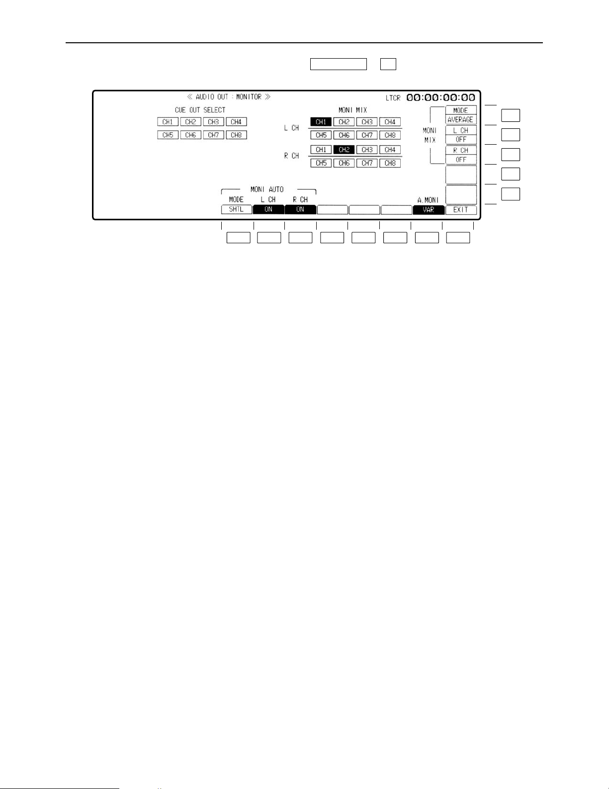
AUDIO OUT MONITOR menu
This menu is displayed by pressing the following keys: >
F7AUDIO OUT
F13
F12
F11
F10
F9
F8F7F6F5F4F3F2F1
Page 61

– 61 –
AUDIO OUT MONITOR menu
Key
F1
F2
F3
F4– F6
F7
F8
F9– F10
F11
F12
F13
Key designation
MODE
For selecting the mode.
L CH
R CH
——
A.MONI
For selecting the audio
monitor output level
adjustment.
EXIT
——
R CH
L CH
MODE
Description
Selects the VTR mode in which the monitor output signals are
automatically switched to the cue signals.
SHTL: Automatically outputs the playback signals of the
cue channel in the SHTL, FF or REW mode.
Outputs the signals of the channel selected by the
L and R buttons in any other mode.
VAR/SHTL:
Automatically outputs the playback signals of the cue
channel in the SHTL, FF, REW, JOG or VAR mode.
Outputs the signals of the channel selected by the L and R
buttons in any other mode.
Selects whether the auto mode is to be activated for the left
channel.
OFF: Always outputs the channel signals selected by the L
button.
ON: Automatically outputs the cue signals in accordance with
the mode selected by F1.
Selects whether the auto mode is to be activated for the right
channel.
OFF: Always outputs the channel signals selected by the R
button.
ON: Automatically outputs the cue signals in accordance with
the mode selected by F1.
Selects whether to adjust the audio monitor output level using
the headphones volume control on the front panel.
UNITY: The audio monitor output level is forcibly fixed at the
UNITY value.
VAR: The level can be adjusted using the headphones
volume control.
Returns the VTR to the AUDIO OUT menu screen.
For setting whether the signals from the left and right channels
are to be mixed and output to the MONITOR connector.
OFF: The signals are not mixed.
ON: The signals are mixed.
For selecting the way in which the channel signals output to the
MONITOR connector are to be mixed.
ADD: Simple addition
AVERAGE: Simple averaging
CUE OUT SELECT
This is used to select the main line CH1 through CH4 (8) signals serving as the CUE output. When the center cursor key is
pressed, CUE OUT SELECT is highlighted, enabling the setting to be selected. (If MONITOR MIX is highlighted, press the F key
and a cursor key (
2
or 1) together to enable this setting to be selected.)
Select the channel using the cursor keys (
2, 1, 3
and 4), and press the center cursor key to turn the selection ON or OFF.
MONITOR MIX
This is used to select the mixed left and right channel signals to be output to the MONITOR connector. As the selection condition,
not more than two channels (maximum 4 channels) among CH1 through CH4 and among CH5 through CH8 can be set to serve
as the left or right channel. When the center cursor key is pressed, MONITOR MIX is highlighted, enabling the setting to be
selected. (If CUE OUT SELECT is highlighted, press the F key and a cursor key (
2
or 1) together to enable this setting to be
selected.)
Select the channel using the cursor keys (
2, 1, 3
and 4), and press the center cursor key to turn the selection ON or OFF.
(This setting is for selecting the channels; whether or not the selected signals are to be actually set is performed by
switching between the F11 and F12 keys.)
Page 62

– 62 –
AUDIO OUT SET UP menu
This menu is displayed by pressing the following keys: >
OR
>
F7SET UP
F8AUDIO OUT
F13
F12
F11
F10
F9
F8F7F6F5F4F3F2F1
Page 63

– 63 –
AUDIO OUT SET UP menu
Key
F1
F2
F3
F4
F5
F6
F7
F8
F9
Key designation
A/V PHASE°
For adjusting the audio
output phase in relation to
the video phase.
JOG PROC
For setting the digital
process ON/OFF.
VAR PROC
For setting the digital
process ON/OFF.
PB FADE
Playback fade.
PB OUT
Selects the audio output
when playback is started.
PEAK HOLD
For setting the peak hold
of the level meter.
SCALE
For switching the level
meter scale.
EXIT
DATA ADV°
Description
When digital signals output from the unit are processed by an
external unit, a phase difference between video and audio
signals can be produced. Such differences can be eliminated by
adjusting the audio and video signal phases.
≥Refer to “Adjusting the audio output signals in relation to the
video signals.”
Selects the digital processing in the JOG mode.
ON: Performs PCM audio digital processing.
OFF: No PCM audio digital processing.
Selects the digital processing in the VAR mode.
ON: Performs PCM audio digital processing.
OFF: No PCM audio digital processing.
Uses V-fade to instantaneously eliminate the audio noise
occurring during playback at the cut edit points.
ON: Activates the playback V-fade processing at all cut edit
points on the tape.
OFF: No playback V-fade processing.
When shifting from stop to play status, some time elapses before
the audio signals are output. This time lapse can be shortened.
INSTANT: Shortens the time lapse before audio is output. The
first part of the audio signal to be output, however,
produces an incomplete sound.
Use for transmission purposes is not recommended.
Convenient when used for search operations, for
instance, because the audio signals can be checked
quickly.
DELAYED: Outputs the audio signals as soon as they are
complete.
For holding the peak recording and playback levels.
ON: Peak level is held.
OFF: Peak level is not held.
For switching the scale of the audio level meter on display to
standard scale or fine scale.
FINE: Scale in 0.2 dB increments. (j24dB to j15dB)
FULL: Standard scale. (j¶ to j0dB)
Refer to “Switching the level meter scale” in the AUDIO IN SET
UP menu section (on page 54).
Returns the VTR to the AUDIO OUT menu screen.
0–1 Fr (in increments of 1/10th of a frame):
The amount by which the data is to be advanced when the
digital audio input/output format is in the data mode is
adjusted. (When “0” is set, the amount is set to the default
setting inside the VTR.)
°This item does not function when the E-E through mode (refer to the description of the F2 key on the AUDIO OUT
SET UP STATE menu) has been set.
Page 64

– 64 –
AUDIO OUT SET UP menu
Key
F10
F11
F12
F13
Key designation
STYLE°
——
STATE
——
Description
This menu item can be set by pressing the F10 key together with
the F key.
PCM: The style is set to the normal PCM audio mode.
DATA: The style is set to the data mode (compressed audio:
Dolby-E).
Transfers the VTR to the AUDIO OUT SET UP STATE menu
screen. (See page 66.)
°The data mode is operational only in the 4-channel audio versions of the 1080/59.94i and 720/59.94p system
formats.
°The items on this menu can also be set on the AUDIO IN SETUP menu. If the setting is updated on one menu, it
will be updated on the other menu as well. Furthermore, these settings cannot be performed on a channel by
channel basis.
Page 65

– 65 –
AUDIO OUT SET UP menu
∑ Adjusting the audio output signals in relation to the video signals
(1) Press the F1 (A/V PHASE) key to put the display in reverse video.
(2) Adjust the phase difference using the ADJUST control.
When the ADJUST control is turned, the display changes to VAR.
(The adjustment can now be varied in 1-sample increments from i16 to j96 samples.)
(3) Upon completion of the adjustment, press the F1 (A/V PHASE) key.
≥When the UNITY/VAR key is pressed during the adjustment, the UNITY mode is restored.
≥When the key is pressed again, the mode reverts to VAR.
∑ Fade function
During editing, the cut-edited data is recorded automatically; during playback, this data is detected and the section concerned is V-faded.
Playback V-fade function OFF Playback V-fade function ON
:
V-fading is performed for an instant to
eliminate the noise.
:
Noise appears at the joins in the editing.
Audio signal (A) Audio signal (B)
UNITY
A/V PHASE
ADJUST
VAR
i4
A/V PHASE
SAMPLES
UNITY
/VAR
Audio signal (A) Audio signal (B)
Page 66

– 66 –
AUDIO OUT SET UP STATE menu
This menu is displayed by pressing the following keys: >>
F12F8AUDIO OUT
Description
NORMAL: The standard mode is established (E-E through
mode is turned OFF).
THROUGH: The E-E through mode (AV minimum delay mode)
is established.
°A discrepancy occurs between the video (audio) output and time
code output in the E-E through mode.
Transfers the VTR to the AUDIO OUT SET UP menu screen.
Key
F1
F2
F3–F7
F8
F9– F13
Key designation
——
EE_MODE
——
EXIT
——
F13
F12
F11
F10
F9
F8F7F6F5F4F3F2F1
Page 67

– 67 –– 67 –
VIDEO OUT SET UP STATE menu
∑ Selecting the TAPE/EE output signals
The video, audio and cue signals which are output during the VTR’s operation are switched on
this menu to TAPE or EE signals.
(1) Press the center cursor key to display the cursor.
(2) Move the cursor to the desired position using the cursor keys.
≥The cursor will not move to places which cannot be set.
(3) Press the center cursor key to select TAPE or EE.
Refer to the following table for the types of setting options.
Center cursor key
Cursor key
≥When a setting is to be established during head selection using the TEST menu or during
editing, the setting applying to the operation concerned takes precedence over the setting
selected using the VIDEO OUT SET UP STATE menu.
≥When TAPE/EE has been set by F1 (OUTPUT) on the HOME menu, the HOME menu setting
takes precedence.
(Underline denotes the factory setting mode.)
Mode
CH
VIDEO
D.AUDIO
CUE
EJECT
FREEZE
BLACK
GRAY
FREE
NOISE
EE1
EE2
MUTE
EE1
EE2
TAPE
EE
STBY
OFF
FREEZE
BLACK
GRAY
FREE
NOISE
EE1
EE2
MUTE
EE1
EE2
TAPE
EE
TENSION
RELEASE
FREEZE
BLACK
GRAY
FREE
NOISE
EE1
EE2
MUTE
EE1
EE2
TAPE
EE
STBY
ON
TAPE
EE1
EE2
MUTE
EE1
EE2
TAPE
EE
REC
TAPE
EE1
EE2
TAPE
EE1
EE2
EE
EDIT
REC
TAPE
EE1
TAPE
EE1
EE
JOG/
VAR
TAPE
TAPE
MUTE
TAPE
SHTL
TAPE
TAPE
MUTE
TAPE
Page 68

– 68 –
AUDIO OUT SDI ASIGN menu
This menu is displayed by pressing the following keys: >>
F12F8AUDIO OUT
F13
F12
F11
F10
F9
F8F7F6F5F4F3F2F1
Page 69

– 69 –
Description
Selects the channels whose signals are to be output to HD SDI
embedded audio channels 1 through 4.
CH1T4: The signals of CH1 through CH4 are output.
CH5T8: The signals of CH5 through CH8 are output.
OFF: No signals are output.
Selects the channels whose signals are to be output to HD SDI
embedded audio channels 5 through 8.
CH1T4: The signals of CH1 through CH4 are output.
CH5T8: The signals of CH5 through CH8 are output.
OFF: No signals are output.
Selects the channels whose signals are to be output to SD SDI
embedded audio channels 1 through 4.
CH1T4: The signals of CH1 through CH4 are output.
CH5T8: The signals of CH5 through CH8 are output.
OFF: No signals are output.
Returns the VTR to the AUDIO OUT menu screen.
Selects the channels whose signals are to be output to HD SDI
embedded audio channels 5 through 8.
CH1T4: The signals of CH1 through CH4 are output.
OFF: No signals are output.
Selects the channels whose signals are to be output to HD SDI
embedded audio channels 1 through 4.
CH1T4: The signals of CH1 through CH4 are output.
OFF: No signals are output.
Selects the channels whose signals are to be output to SD SDI
embedded audio channels 1 through 4.
CH1T4: The signals of CH1 through CH4 are output.
OFF: No signals are output.
Key
F1
F2
F3
F4
F5– F7
F8
F9
F10
F11– 12
F13
Key designation
HD_TO_HD
CH1T4
HD_TO_HD
CH5T8°
——
HD_TO_SD
CH1T4
——
EXIT
SD_TO_HD
CH5T8°
SD_TO_HD
CH1T4
——
SD_TO_SD
CH1T4
AUDIO OUT SDI ASIGN menu
°This setting is not displayed when the digital sound is in the 4-channel format.
Page 70

– 70 –
TC/CHR menu
This menu is displayed by pressing the following key:
TC/CHR
F13
F12
F11
F10
F9
F8F7F6F5F4F3F2F1
Page 71

– 71 –
TC/CHR menu
Description
INT: Built-in time code generator.
EXT LTC: LTC time code from TIME CODE input connector.
S LTC: LTC time code added to serial signals; not displayed
when the SD mode is selected.
S VTC: VTC time code added to serial signals; not
displayed when the SD mode is selected.
EXT VITC: VITC time code added to video signals; not
displayed when the HD mode is selected.
≥When the F1 (SOURCE) key is at [INT], AUTO, PRESET and
SALVE are displayed.
AUTO: Generator locks at the value read out by the
reader. In this case there is no time code setting.
(Only during editing.) During normal recording,
however, any setting of the generator can be
performed.
PRESET: Generator does not lock at the value read out by
the reader. Generator can be set freely.
SLAVE: The generator is locked to the reader’s readout
value. In this case, the time code cannot be set.
≥When the F1 (SOURCE) key is at [TEXT LTC], SALVE and
DIRECT are displayed.
SLAVE: Generator locks to external LTC time code.
(When there is no external input, E-TC time data
blinks. )
DIRECT: External LTC time code is recorded as is.
(When there is no external input, E-TC: ¢¢:¢¢:
¢¢:¢¢are displayed.)
≥When the F1 key is at [S VITC], [S LTC] or [EXT VITC], this key
is not displayed.
In this case, the generator value typically locks to external VITC
or LTC time code.
ON: User bit locks to user bit value read by reader (TCR) or to
external user bit value, and cannot be set.
OFF: Generator does not lock to value read out by reader. User
bit value can be set freely.
REC RUN: Runs the TC only while recording is in progress.
FREE RUN: Runs the TC all the time in the same way as a
clock.
Valid only when the F1 (SOURCE) key selects [INT].
ON: Drop frame mode is set.
OFF: Non-drop frame mode is set.
≥When [EXT LTC], [S VITC] or [S LTC] is selected in the F1
key, the VTR conforms to drop/non-drop frame mode of
external time code.
Key
F1
F2
F3
F4
F5
Key designation
SOURCE
For selecting
internal/external time code
signal.
TC SLAVE
For setting up time code
slave lock mode.
UB SLAVE
User bit lock.
RUN MD
Time code progress.
DF MD°
For selecting drop or
non-drop frame.
°This is not displayed when the 1080/23p, 1080/24p or 1080/50i system format has been selected.
Page 72

– 72 –
TC/CHR menu
Description
ON: CF BIT is recoorded.
OFF: CF BIT is not recorded.
≥When [EXT LTC], [S VITC] or [S LTC] is selected in the F1 key,
the VTR conforms to the external color frame bit.
Transfers the VTR to the TC/CHR SET UP menu screen.
Transfers the VTR to the TC/CHR CONVERT menu screen.
LTC: LTC is read out all the time.
AUTO: At low speed, VITC is read preferentially. When it is not
read, then LTC is read.
VITC: VITC is read out all the time.
≥In either setting, when the time code cannot be read, values
corrected by control signal are read out. (Interpolation mode is
assumed and [INTRP] is displayed on the HOME menu.)
TC: Only the TC is superimposed.
TC.ST: The TC and VTR status are superimposed.
TC.UB: The TC and user bits are superimposed.
TC.ST.RT: The TC, VTR status and remaining tape time are
superimposed.
OFF: No superimposed display.
ON: The warning displays are superimposed.
OFF: The warning displays are not superimposed.
REVERSE: Characters appear against a black background.
INTENSE: Characters are displayed more intensely.
Key
F6
F7
F8
F9
F10
F11
F12
F13
Key designation
CF BIT°
1
For selecting the color
frame bit ON/OFF during
recording.
——
SETUP
CONVERT°
2
TCR
For selecting time code
read out mode.
SUPER
For setting superimpose.
SUPER ERR
CHR TYPE
For selecting type of
character to be
superimosed.
°1This is displayed only when the 480/59.94i system format has been selected.
°
2
This is displayed only when the 1080/23p, 1080/24p or 1080/50i system format has been selected.
Page 73

– 73 –
TC/CHR menu
∑ Changing the superimposing position
(1) Move the position using the cursor keys.
≥When a cursor key is held down, the cursor will move more
quickly.
≥When the center cursor key is pressed, the superimposing re-
turns to its initial position.
∑ Time code displays and VTR’s operating modes
Display the time codes and VTR’s operating modes as required.
Time code displays
CTL1: Control signal 1 TCG: Value generated by time code generator
CTL2: Control signal 2 LUBG: Value of LTC user bit generated
LTCR: LTC time code readout value VUBG: Value of VITC user bit generated
LUBR: LTC user bit readout value EXTC: External time code value
VTCR: VITC time code readout value EXUB: External user bit value
VUBR: VITC user bit readout value
≥The colon (“:”) between the seconds and frames denotes the readout mode of the time code
reader.
Hours Minutes Seconds Frames
;; ; ;
∑∑ : ∑∑ : ∑∑ : ∑∑. <Blinking display: Time code cannot be read out.
[. ]: DF mode ON
[: ]: DF mode OFF
[]: First field
[. ]: Second field
[: ]: Time code can be read out or TCG value is displayed.
[]: Time code cannot be read out.
Center cursor key
Cursor keys
Page 74

– 74 –
TC/CHR menu
∑ Time code displays and VTR’s operating modes (continued)
VTR’s operating modes
STOP F.FWD
PREVIEW REW
REVIEW EDIT PLAY (edit playback)
PREROLL EDIT REC (edit recording)
AUTO EDIT (automatic editing) CUE UP
JOG STANDBY OFF
VAR EJECT
SHTL DMC PREVIEW
REC DMC EDIT
REC
(display blinks during Pre-CTL operation) OUT PREVIEW
PLAY DMC SAMPLE
(variable memory speed sampling underway)
P PLY (programmed playback) DMC PLAY (variable memory playback underway)
TSO (TAPE SPEED OVERRIDE) AUTO OFF
≥In the shuttle/variable mode and CUE UP and PREROLL modes, the tape travel direction is in-
dicated as “i” or “j”, and the tape speed is displayed as an integer.
≥In the jog mode, the tape travel is indicated by “O” when it is moving in the forward direction,
by “¢” when it has stopped, and by “N” when it is moving in the reverse direction.
≥In the programmed playback and TSO modes, “i” or “j” is used to indicate the deviation di-
rection, and the deviation data is displayed as a percentage.
∑ Error information displays
Press the F12 (SUPER ER) key to set it ON.
The error information will now be displayed.
FAN STOP (fan stopped) HD REF ERROR (no HD reference signal input)
ERASE ERROR (erase current stopped) SD REF ERROR (no SD reference signal input)
COMP.CPU ERROR HD SDI ERROR (HD SDI signal error)
(error in communication with CPU)
CONCEAL SW OFF SD SDI ERROR (SD SDI signal error)
(conceal SW at “OFF” position)
ECC SW OFF (ECC SW at “OFF” position) FREQ UNMATCH
(frequency settings fail to match)
SERVO UNLOCK (no servo lock) VIDEO ERROR (video system error)
CTL NOT DET. (no CTL signal detection) PCM ERROR (PCM signal system error)
LOW RF (drop in RF level during recording) RS-422 ERROR (RS-422 system error)
CONCEAL V/A (video/audio error corrected) RS-232C ERROR (RS-232C system error)
CONCEAL A (audio error corrected) VA-CONT ERROR (VA controller error)
CONCEAL V (video error corrected) TC ERROR (time code error occurred)
AUDIO MUTE (audio output muted) CARD LOW BATT
(low charge in front IC card battery)
HIGH ERROR (inner error value too high) SYSCON ERROR
(system control system error occurred)
CTL HEAD CLOG (CTL head clogged) MECHA ERROR
(mechanical system error occurred)
LTC HEAD CLOG (LTC head clogged) SERVO ERROR
(reel, drum or capstan error occurred)
OPT ERROR (optimization system error) SYSTEM ERROR (other error)
Page 75

– 75 –
TC/CHR menu
Table of user bit settings
F1 (SOURCE)
INT (internal) TC
S LTC
S VITC
EXT LTC
EXT LTC
F2 (TC SLAVE)
——
——
SLAVE
DIRECT
F3 (UB SLAVE)
ON
OFF
ON
OFF
ON
OFF
F10 (TCR)
LTC
AUTO
VITC
LTC
AUTO
VITC
LTC
AUTO
VITC
LTC
AUTO
VITC
LTC
AUTO
VITC
LTC
AUDIO
VITC
LUBG mode
REGEN
INT UB
PRESET
INT UB
EXT REGEN
INT UB
PRESET
INT UB
DIRECT
VUBG mode
INT UB
REGEN
INT UB
PRESET
INT UB
EXT REGEN
INT UB
PRESET
INT UB
EXT REGEN
INT UB
PRESET°
°The user bit can be set in all modes except for recording.
DIRECT: The external LTC input signal is recorded directly and output.
It is not synchronized with the internal reference signal.
REGEN: The user bit is slave-locked to the value read out on the tape.
The user bit cannot be set.
EXT REGEN: The user bit is slave-locked to the externally input VITC or LTC.
The user bit cannot be set.
PRESET: The user bit is not locked to the value read out on the tape or external input.
The user bit can be set.
INT UB: In this mode, the previous user bit is retained, and neither the REGEN nor PRESET functions
can be implemented.
To set the user bit again, use the F1 (SOURCE), F2 (TC SLAVE) or F3 (UB SLAVE) key to
select one of the three modes above.
Page 76

– 76 –
TC/CHR SET UP menu
This menu is displayed by pressing the following keys: )
OR
)
F5SET UP
F8TC/CHR
F13
F12
F11
F10
F9
F8F7F6F5F4F3F2F1
Page 77

– 77 –
TC/CHR SET UP menu
Key
F1–F6
F7
F8
F9
F10
F11
F12
F13
Key designation
TCG OUT
EXIT
VITC.L
VITC
For superimposing VITC
onto the SD output.
——
VITC
For selecting the VITC.
LTC
For selecting the LTC.
Description
For selecting whether to latch the TCG display and LTC output
using the INPUT CHECK key°.
MOMNT: Establishes the INPUT CHECK mode only while the
key is held down.
LATCH: The INPUT CHECK mode is established when the
INPUT CHECK key is pressed, and it is held even
when the key is released. The mode is released in a
mode other than the EJECT, STBY ON/OFF or STOP
mode or when the F1 (OUTPUT) key on the HOME
menu is pressed.
Returns the VTR to the TC/CHR menu screen.
For transferring to the VITC LINE selection menu.
SD mode: The recording VITC superimposing
and the lines in which it is
superimposed are set. The
playback VITC superimposing and
the lines in which it is
superimposed are set.
HD mode: The DOWN CON SD output VITC superimposing
and the lines in which it is superimposed are set.
For selecting whether the VITC information is to be
superimposed on SD recording and output.
ON: VITC is superimposed.
OFF: VITC is not superimposed.
For selecting whether the VITC information is to be carried on
the HD SDI output.
Selects whether the VITC is to be carried.
ON: VITC is carried.
OFF: VITC is not carried.
For selecting whether the LTC information is to be carried on the
HD SDI output.
Selects whether the LTC is to be carried.
ON: LTC is carried.
OFF: LTC is not carried.
°The video input signals can be checked at the SD SDI MONITOR OUT or HD SDI MONITOR OUT connector, and
the audio input signals can be checked at the MONITOR connector and HEADPHONES jack; these signals are
switched to the input signals while the INPUT CHECK key is held down.
NTSC: 10– 20 lines
(Default 14, 15)
PAL: 8 –22 lines
(Default 11, 13)
Page 78

– 78 –
TC/CHR SET UP VITC.L menu
This menu is displayed by pressing the following keys: ))
OR
)).
F9F5SET UP
F9F8TC/CHR
Key
F1–F7
F8
F9
F10–F13
Key designation
——
EXIT
VITC.L
——
Description
Returns the VTR to the TC/CHR menu screen.
SD mode: The superimposing of the recording VITC and the
lines where it is to be superimposed are set.
The superimposing of the playback VITC and the
lines where it is to be superimposed are set.
HD mode: The superimposing of the DOWN CON SD output
VITC and the lines where it is to be superimposed
are set.
F13
F12
F11
F10
F9
F8F7F6F5F4F3F2F1
Page 79

– 79 –
TC/CHR SET UP VITC.L menu
∑ Selecting the line where VITC is to be inserted
1. Use the cursor keys (2, 1) to select the lines where VITC is to be inserted.
The line numbers shown in the boxes on the screen indicate the recommended insertion
lines (lines 14 and 16 for NTSC and lines 11 and 13 for PAL).
2. To select other lines, press the center cursor key.
(Up to two lines can be selected for insertion.)
Center
cursor key
Cursor key
Page 80

– 80 –
°1This can be set only when the 1080/23p or 1080/24p system format is set and when F11, F12 or F13 key has been
set to CONVERT.
°
2
These keys are displayed only when the 1080/23p or 1080/24p system format has been selected.
TC/CHR CONVERT menu
This menu is displayed by pressing the following keys: )
F9TC/CHR
Key
F1
F2–F5
F6
F7
F8
F9–F10
F11
F12
F13
Key designation
TC SYNC°
1
For selecting the point at
which the TC value is to
be set.
——
DF MD°
2
——
EXIT
——
SD SUPER°
2
HD SUPER°
2
LTC OUT°
2
Description
For selecting the point at which the TC value is to be set when
the time code is converted.
When this key is pressed, the window is opened, and the TC
value can be input.
For selecting drop frame or non-drop frame of the time code
signals, which are to be TC converted and output, for the 3:2
pull-down output from 1080/23p or 1080/24p.
DF: Drop frame is set.
NDF: Non-drop frame is set.
Returns the VTR to the TC/CHR menu screen.
CONVERT: Counts up at 30 frames.
ORIGINAL: Counts up at 24 frames.
CONVERT: Counts up at 30 frames.
ORIGINAL: Counts up at 24 frames.
CONVERT: Counts up at 30 frames.
ORIGINAL: Counts up at 24 frames.
F13
F12
F11
F10
F9
F8F7F6F5F4F3F2F1
Page 81

– 81 –
MULTI CUE menu
This menu is displayed by pressing the following key:
MULTI CUE
F13
F12
F11
F10
F9
F8F7F6F5F4F3F2F1
Page 82

– 82 –
MULTI CUE menu
Key
F1
F2
F3
F4
F5
F6
F7
F8
F9
F10
F11
F12
F13
Key designation
1
For designating the cue
number 1 and page.
2
For designating the cue
number 2 and page.
3
For designating the cue
number 3 and page.
4
For designating the cue
number 4 and page.
5
For designating the cue
number 5 and page.
PROTECT
For designating protection
on a page by page basis.
——
SET UP
6
For designating the cue
number 6 and page.
7
For designating the cue
number 7 and page.
8
For designating the cue
number 8 and page.
9
For designating the cue
number 9 and page.
10
For designating the cue
number 10 and page.
Description
Designates the cue number for registering the cue point.
When the key is pressed together with the F key, the page for
registering the point is also designated.
This function is executed by pressing this key together with the F
key.
ON: Sets the displayed page to the protected status. Cue
points on this page cannot be registered, changed or
cleared.
OFF: Releases the protected status of the page displayed. Cue
points on this page can be registered, changed or cleared.
Transfers to the MULTI CUE SET UP menu screen.
Designates the cue number for registering the cue point.
When the key is pressed together with the F key, the page for
registering the point is also designated.
Page 83

MULTI CUE menu
∑ Switching the pages
≥A particular page can be selected by pressing one of the F1 (1) through F5 (5) or F9 (6) through
F13 (10) keys together with the F key.
≥The pages are scrolled up when the F key and “1” key are pressed together.
≥The pages are scrolled down when the F key and “2” key are pressed together.
If an attempt is made to scroll down from page 1, page 10 will be displayed.
If an attempt is made to scroll up from page 10, page 1 will be displayed.
∑ Protecting pages
When the F6 (PROTECT) key and F key are pressed together, the protected status is set for the
page displayed.
When the F6 key and F key are pressed together again, the protected status is released.
Once protected, the number of the page is displayed as follows:
Protected status Protection released status
∑ Entering cues
Up to a hundred cue points can be entered.
(1) Select the number of the cue point to be entered.
Press one of the F1 through F5 or F9 through F13 keys. The number corresponding to the
pressed key appears in reverse video.
(2) Input the time code.
There are three ways of inputting the time code.
1) Use the search dial to search the cue point, and press the ENTRY button.
2) Input the time code directly using the number keys, and press the ENT key.
3) Move the cursor to the section where the value can be captured.
1. Press the FROM key.
1. The time code of the cursor position is captured in the scratchpad register.
2. Increment or decrement the number using the “i,” “j” and number keys.
3. Press the ENT key.
1. The result of the operation is now displayed.
– 83 –
4
PAGE
F
1
PAGE1PAGE
FROM
00
44
SPR DATA
07 04
3
00 44 07 07
SPR DATA
ENT
Page 84

– 84 –
MULTI CUE menu
4. Move the cursor to the section where the captured time code is to be displayed.
5. Press the COPY key to call the captured time code.
5. The cue data is now entered.
≥The position of the next cue number automatically appears in reverse video when the F1
(AUTO STEP) key on the MULTI CUE SET UP menu has been set to ON.
≥An entered cue point remains in the memory even when the power is turned off.
∑ Changing cue points
Proceed as follows to change an already entered cue point.
(1) Press the key (F1 – F5, F9 –F13) corresponding to the cue to be entered.
(2) Press the cursor keys to move the column cursor to the time code of the cue point to be
changed.
(3) Press the center cursor key to change the cursor to the column cursor, and then input the
value using the number keys.
(4) Press the ENT key.
∑ Clearing cue data
Proceed as follows to clear an already entered cue point.
(1) Press the key (F1 – F5, F9 –F13) corresponding to the cue to be cleared.
(2) Press the C key.
(3) Press the ENT key.
∑ Clearing all the cue points
Press the F8 (SET UP) key, and then press the F3 (PAG CLR) on the SET UP menu and F key
together. All the cue points on the page concerned are now cleared. To clear all the cue points
on all the pages (with the exception of the cue points on protected pages), press the F5 (ALL
CLR) and F key together.
Cursor
Center cursor key
Cursor key
4
:::
4
00:44:07:07
COPY
4
00:44:07:07
0 0 4 4 0 7 0 4
4
00:44:07:04
Page 85

– 85 –
MULTI CUE SET UP menu
This menu is displayed by pressing the following keys: )
F8MULTI CUE
F13
F12
F11
F10
F9
F8F7F6F5F4F3F2F1
Page 86

– 86 –
MULTI CUE SET UP menu
Key
F1
F2
F3
F4
F5
F6–F7
F8
F9
F10
F11
F12
F13
Key designation
AUTO STEP
For setting the auto step
mode.
PAG MODE
For setting the cursor
movement mode.
PAG CLR
For clearing cue data on a
page.
——
ALL CLR
For clearing all the cue
data.
——
EXIT
CLUTCH
For setting the dial clutch
in the VAR mode.
MAX SP.
For setting the maximum
tape speed in the VAR
mode.
AUTO FRZ°
For setting the freeze
frame output in the VAR
mode.
——
CUE ROLL
For setting the preroll time.
Description
ON: Moves the cursor to the next item automatically when a
cue point is registered.
OFF: Cursor is not moved.
≥When F2 (PAG MODE) below is at ON, the cursor moves only
on the page.
≥For example, upon completion of registration of cue point
number 10, the cursor moves to the time code input site of cue
number 1 on the same page.
≥When F2 (PAG MODE) below is at OFF, the cursor moves
between two pages.
≥For example, upon completion of registration of cue point
number 10, the cursor moves to the time code input site of cue
number 1 on the next page.
ON: Cursor moves only on the same page.
OFF: Cursor moves between two pages.
All the cue data on a page is cleared.
This function is executed when the key is pressed together with
the F key.
≥Data on a protected page is not cleared.
All the cue data is cleared.
This function is executed when the key is pressed together with
the F key.
≥Data on a protected page is not cleared.
Returns the VTR to the MULTI CUE menu screen.
ON: Sets the clutch to the j1a, 0a, i1a or i2a speed.
OFF: The clutch is not set.
s1<>r2: Tape speed in the range of j1 to i2
s1<>r1: Tape speed in the range of j1 to i1
0<>r1: Tape speed in the range of 0 to i1
ON: A freeze frame is output when the EXECUTE button is
pressed during variable mode. (Tape running continues.)
The setting is released when the STOP, PLAY, FF, REW,
JOG, VAR or SHTL button is pressed.
OFF: A freeze frame is not output.
Sets the preroll time.
Preroll time can be set in 1-second steps from 0 to 30 sec.
°This item is operational on the MULTI CUE menu screen.
Page 87

– 87 –
INSERT/ASSEMBLE MANUAL EDIT menu
Press the (or )> keys to display the MANUAL EDIT menu.
F12INSERTASSEM
Key
F1– F7
F8
F9
F10–F11
F12
F13
Key designation
——
SET UP
INSERT/ASSEMBLE
For setting the editing
mode ON/OFF.
——
AUTO EDIT
CH SELECT
For selecting the editing
channel.
Description
Transfers the VTR to the MANUAL EDIT SET UP menu screen.
Selects the editing mode.
ON: Sets the editing mode to ON.
OFF: Sets the editing mode to OFF.
Transfers the VTR to the AUTO EDIT menu screen.
Transfers the VTR to the INSERT MANUAL EDIT CH SELECT
(editing channel selection) menu screen (but only for insert
editing).
F13
F12
F11
F10
F9
F8F7F6F5F4F3F2F1
Page 88

– 88 –
INSERT MANUAL EDIT CH SELECT menu
This menu is displayed by pressing the following keys: >>
F13F12INSERT
°CH-5 to CH-8 are not displayed when PCM audio has been set to the 4-channel format.
F13
F12
F11
F10
F9
F8F7F6F5F4F3F2F1
Page 89

– 89 –
INSERT MANUAL EDIT CH SELECT menu
Key
F1
F2
F3
F4
F5
F6
F7
F8
F9
F10
F11
F12
F13
Key designation
VIDEO
For selecting the video
channel ON/OFF.
CH-1
For selecting the audio
CH1 ON/OFF.
CH-2
For selecting the audio
CH2 ON/OFF.
CH-3
For selecting the audio
CH3 ON/OFF.
CH-4
For selecting the audio
CH4 ON/OFF.
CUE
For selecting the cue
channel ON/OFF.
TC
For selecting the LTC time
code channel ON/OFF.
SET UP
CH-5
For selecting the audio
CH5 ON/OFF.
CH-6
For selecting the audio
CH6 ON/OFF.
CH-7
For selecting the audio
CH7 ON/OFF.
CH-8
For selecting the audio
CH8 ON/OFF.
CH SELECT
Description
For selecting the editing channel.
Valid only for insert editing.
ON: Selected as the editing channel.
OFF: Not selected as the editing channel.
≥In the case of insert editing with selection of digital audio
channel only, be sure to continue with a stabilized input video
signal.
≥If the input video signal is distorted, audio might not be
recorded properly.
Transfers the VTR to the MANUAL EDIT SET UP menu screen.
For selecting the editing channel.
Valid only for insert editing.
ON: Selected as the editing channel.
OFF: Not selected as the editing channel.
≥In the case of insert editing with selection of digital audio
channel only, be sure to continue with a stabilized input video
signal.
≥If the input video signal is distorted, audio might not be
recorded properly.
Transfers the VTR to the INSERT MANUAL EDIT menu screen.
Page 90
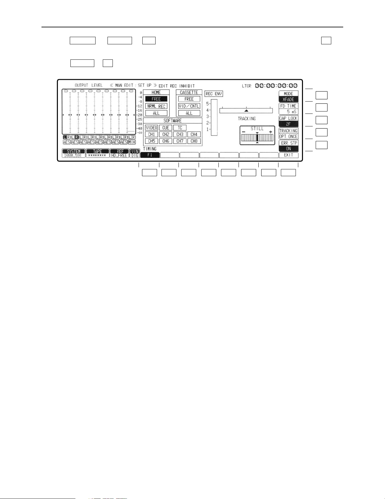
– 90 –
INSERT/ASSEMBLE MANUAL EDIT SET UP menu
Press the (or )> keys to change to the MANUAL EDIT menu, then press the key
to display this menu.
OR
Press the > keys to display this menu.
F2SET UP
F8F12INSERTASSEM
F13
F12
F11
F10
F9
F8F7F6F5F4F3F2F1
Page 91

– 91 –
INSERT/ASSEMBLE MANUAL EDIT SET UP menu
Key
F1
F2–F7
F8
F9
F10
Key designation
TIMING°
For setting the edit timing.
——
EXIT
ERR.STP
Error stop.
TRACKING
For adjusting the tracking.
Description
Sets the timing with which to record the fields at the edit IN point
and OUT point. This menu item can be set by pressing the F1
key and the F key together.
F1: Editing starts from the odd-numbered field at the IN
point, and it ends when an even-numbered field one
frame before the OUT point is recorded.
F2: Editing starts from the even-numbered field at the IN
point, and it ends when an odd-numbered field at the
OUT point is recorded.
F1/F2:
The fields for the edit IN point and OUT point are determined
by the timing at which the edit command is issued.
If the edit timing command is issued in an evennumbered field, editing is ended in an odd-numbered
field; conversely, if the edit timing command is issued in
an odd-numbered field, editing is ended in an evennumbered field.
≥
The edit timing can also be set on the AUTO EDIT SET UP menu.
If a different mode has been set on the AUTO EDIT SET UP
menu, the mode which has been set on the INSERT/ASSEMBLE
MANUAL EDIT SET UP menu will be changed.
≥The F1 setting is forcibly established when the CONTROL
(REMOTE/LOCAL) switch has been set to LOCAL.
Returns the VTR to the MANUAL EDIT menu screen.
When the ENV value at which editing started (5 frames before)
has dropped to 25% below the REC ENV value when optimizing
was completed, an error is considered to have occurred, and one
of the following operations is selected.
ON: During execution of editing in optimize mode, if an error
has occurred up to the IN point, editing is aborted and the
stop mode is assumed.
OFF: Displays a message and continues editing when an error
has occurred.
Under normal times, tracking adjustment is not necessary.
Adjustment is made if tracking disparities have occurred during editing.
VAR: The tracking can be adjusted manually.
Refer to “Manually adjusting the tracking” (on page 96).
FIX: The tracking is fixed.
OPT ONCE: At the initial editing after the cassette has been
inserted, the tracking is optimized while the tape is
playing back up to the IN point. The tracking is not
subsequently optimized.
When the PLAY button and STAND BY button are
pressed together during EDIT/PLAY, the tracking is
optimized again, and it is optimized with each
EDIT/PLAY operation.
OPT AUTO: The tracking is optimized while the tape is playing
back up to the IN point with each editing operation,
and it is retained even if the VTR is transferred to
another menu.
Refer to “Automatically adjusting the tracking.”
°This item cannot be displayed when the 1080/23p or 1080/24p format has been selected. (It is forcibly set to F1.)
Page 92

– 92 –
INSERT/ASSEMBLE MANUAL EDIT SET UP menu
Key
F11
F12
F13
Key designation
CAP LOCK
For setting the capstan
servo lock.
FD TIME°
For setting the audio fade
time.
MODE°
For setting the audio fade
edit.
Description
For selecting the capstan servo lock mode during playback.
4F AUTO (8F AUTO: 1080/23p, 1080/24p, 1080/50i):
Assumes the color frame auto lock mode. If discontinuity is
produced in the color frame during playback, the unit locks again
to a new color frame.
4F FORCE (8F FORCE: 1080/23p, 1080/24p, 1080/50i):
Assumes the color frame forced lock mode. If there is any
discontinuity in the color frame during playback, the unit
preserves the field sequence at initial lock.
2F: Assumes frame lock mode.
≥The capstan servo lock mode can be set in HOME SET UP
menu. If the two settings differ, priority is given to the final
mode setting.
Valid when the F13 key is set to X FADE or V FADE.
The times that can be set are as follows: 5, 10, 15, 20, 25, 50,
100 ms.
(Initial setting is 5 ms.)
For the setting procedure, refer to “Selecting the audio fade time”
(on page 97).
Audio editing can be accomplished while cross-fade editing prior
playback audio and input audio or V-fade editing.
X FADE: Performs audio cross-fade editing.
CUT: Performs cut (normal) editing.
V FADE: Performs audio V-fade editing.
°Only CUT can be selected when TAPE has been selected as the EDIT REC STATE setting. However, FADE can be
selected by pressing this key and F key together, in which case the EDIT REC STATE setting is switched to EE1.
Page 93

– 93 –
INSERT/ASSEMBLE MANUAL EDIT SET UP menu
∑ EDIT REC INHIBIT mode display
This display shows the statuses of the editing inhibit modes.
≥SOFTWARE
≥The editing inhibit modes selected for each channel are shown
here. Refer to “Selecting the SOFTWARE inhibit channels.”
≥VIDEO: Video channel editing is inhibited.
≥CH1– CH8
(CH4): Digital audio channel editing is inhibited.
≥CUE: Cue channel editing is inhibited.
≥TC: Time code channel editing is inhibited.
≥HOME
≥The recording inhibit modes established using the F13 (REC
INH) key on the HOME menu are shown here.
≥FREE: Recording can be performed.
≥NRML REC: The normal recording mode is inhibited.
≥ALL: All recording/editing operations are inhibited.
≥CASSETTE
≥The recording inhibit modes established by the cassette tape are
shown here.
≥FREE: Recording can be performed.
≥VID/CNTL: The video and control signals are inhibited.
≥ALL: All recording/editing operations are inhibited.
∑ Sequence of priority for recording inhibit modes
A sequence of priority applies to the inhibit modes and, depending on which modes have been
selected, it may not be possible to perform recording. If, for example, “ALL” has been selected
for CASSETTE, no editing or recording will be possible regardless of the other settings.
First: CASSETTE
Second: HOME
Third: SOFTWARE
Page 94
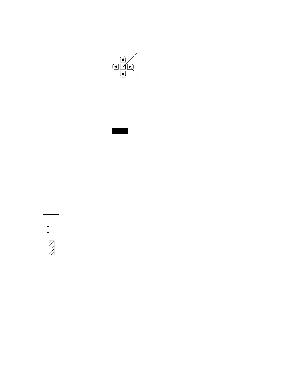
– 94 –
INSERT/ASSEMBLE MANUAL EDIT SET UP menu
∑ Selecting the SOFTWARE inhibit channels
(1) Press the center cursor key. The cursor now appears.
(2) Press the cursor key to move the cursor to the channel where editing is to be inhibited.
(3) Press the center cursor key. Once the display appears in reverse video, the selection of the
editing inhibit channel is completed. When the center cursor key is pressed again, the editing
inhibit is released.
(3) ≥Assembly editing cannot be selected if there is even one editing inhibit channel.
ONotesN
≥When ALL or PRE CTL has been set for CASSETTE EDIT REC INHIBIT or HOME REC IN-
HIBIT, all recording and editing operations will be inhibited.
≥When VIDEO/CNTL has been set for CASSETTE EDIT REC INHIBIT, editing inhibit applies to
the video channel at all times.
∑ REC ENV display
This shows the RF envelope level at which sound is played back from the rotary recording heads during
playback.
CH4
CH4
Center cursor key
Cursor key
5
4
3
2
1
REC ENV
Page 95

– 95 –
INSERT/ASSEMBLE MANUAL EDIT SET UP menu
∑ Tracking
≥Automatically adjusting the tracking (optimizing)
To optimize the tracking automatically, press the F10 (TRACKING) key to select OPT ONCE or
OPT AUTO.
Set the preroll time to 5 seconds or more.
≥At the OPT ONCE setting, the tracking is optimized only once while the tape is playing up to
the IN point during the first editing after the cassette has been inserted. The tracking is not subsequently optimized, and the value is fixed.
≥At the OPT AUTO setting, the tracking is optimized while the tape is playing up to the IN point
with each editing.
ONotesN
≥The OPT ONCE setting is suitable when continuous editing is to be performed such as in the
case below. (If OPT AUTO is set when this kind of editing is to be performed, the tracking error
may build up.)
Base Edit 1 Edit 2 Edit 3 Base
≥The OPT AUTO setting is suitable when intermittent editing is to be performed such as in the
case below.
Base Edit 1 Base Edit 2 Base
≥Proceed as follows to optimize the tracking again using OPT ONCE.
≥(1) Press the INSERT or ASSEMBLE button to highlight the F9 key and establish the editing
mode. Check that the INSERT or ASSEMBLE LED has lighted.
≥(2) Press the PLAY button to establish the PLAY (EDIT PLAY) mode.
≥(3) Optimizing is initiated by pressing the PLAY and STAND BY buttons together.
ONotesN
≥(1) The optimized tracking value is retained even when the VTR is transferred to another
menu.
≥(2) The following message appears while the tracking is being optimized, and the ∆ mark that
indicates the tracking value appears to show the progress made in the processing.
OPTIMIZING
Upon completion of the optimizing, the following message appears, the TRACK OPT appears on the INSERT/ASSEMBLE MANUAL EDIT and HOME menu screens.
COMPLETE
ASSEM INSERT
Page 96

INSERT/ASSEMBLE MANUAL EDIT SET UP menu
VAR
TRACKING
5
4
3
2
1
REC ENV
ADJUST
(3) The following message appears and optimizing is suspended in the following cases:
≥When the VTR is set to a mode other than PLAY while optimizing is underway.
≥When optimizing has failed.
≥When no video signals have been recorded on the tape.
≥When no CTL signals have been recorded on the tape.
NOT COMPLETE
At times like these, the center value (0) is set as the optimized value.
(4) If the optimizing processing fails to be completed even after 5 seconds, the following mes-
sage appears and optimizing is suspended.
TIME OVER
(5) When the cassette is ejected, the optimized value is canceled.
∑ Manually adjusting the tracking
(1) Insert the tape, and play it back.
(2) Press the F10 (TRACKING) key and set it to VAR.
(3) Turn the ADJUST control, and adjust it so that the envelope level is set to its maximum.
– 96 –
Page 97

INSERT/ASSEMBLE MANUAL EDIT SET UP menu
V
X
V
X
X FADE
MODE
10
FD TIME
25
ADJUST
∑ Selecting the audio fade time
(1) Press the F13 (MODE) key to set it to X FADE or V FADE.
(2) Press the F12 (FD TIME) key.
(3) Turn the ADJUST control to select the audio fade time.
V FADE X FADE V FADE
Advance playback
signals
Insert signals
Advance playback
signals
Fade time
IN point
OUT point
ONoteN
The V fade time is a multiple of the time set for FD TIME.
If, for instance, FD TIME is to be set to 100ms:
X fading
100 ms
V fading
200 ms
100 ms
100 ms
Fade time
The solid lines indicate X fading.
The broken lines indicate V fading.
– 97 –
Page 98

INSERT/ASSEMBLE AUTO EDIT menu
The AUTO EDIT menu is displayed by pressing the following keys: or #
INSERTASSEM
F8F7F6F5F4F3F2F1
F12
F13
F12
F11
F10
F9
– 98 –
Page 99

INSERT/ASSEMBLE AUTO EDIT menu
F1
F2
F3
F4
F5
F6
F7
F8
F9
F10
F11
F12
F13
Key
Key designation
LAST X
For calling the edit data to
be input.
LAST ED
For calling all the last data
edited.
W/PLYR
Continuous VTR remote
control ON/OFF.
VAR MEMO
Variable memory.
PLYR SEL
Selects player for remote
control.
R/P SEL
Selects VTR for operation.
TRIM
Frame correction of edit
point.
SET UP
INSERT
For setting the editing
mode ON/OFF.
SPLIT
Split editing ON/OFF.
——
MANUAL EDIT
CH SELECT
Edit channel selection.
Description
When the F1 key is pressed, “LOAD” is displayed, and the edit
data which was input last is called.
When the F2 key is pressed, “LOAD” is displayed, and all the
data which was edited last is called.
Performs remote control of VTR connected by RS-422A.
ON: Remote control possible.
OFF: Unit operated independently.
≥See also F5 (PLYR SEL) key.
This function stores the playback speed and direction settings
established by the search dial in its memory and automatically
reproduces these settings. (At times, these settings are
reproduced by one’s own VTR; at other times, they may control
the player that is connected.)
ON: Enables the variable memory function.
OFF: Disables the variable memory function.
PLYR-1: Controls the VTR connected to REMOTE OUT
connector.
PLYR-2: Controls the VTR connected to REMOTE IN/OUT
connector.
PLAYER: Performs remote control of the player selected by
F5 (PLYR SEL) key.
PECORDER: Control is the main unit (recorder) only.
ON: Registered edit points are corrected by frame unit.
OFF: Releases trim function.
Transfers the VTR to the AUTO EDIT SET UP menu screen.
ON: Sets the editing mode ON.
OFF: Sets the editing mode OFF.
This function registers each audio and video edit point during
insert editing.
ON: Enables split editing.
OFF: Releases split editing.
(For details, refer to pages 40 and 41 in the Hardware Operating
Instructions.)
Transfers the VTR to the MANUAL EDIT menu screen.
Transfers the VTR to the INSERT AUTO EDIT CH SELECT
(editing channel selection) menu screen (but only for insert
editing).
– 99 –
Page 100

INSERT/ASSEMBLE AUTO EDIT menu
INP:::
IN 0P:::
0 0 0 0 3 4 1 4
∑ Tape position indicator
This indicates the edit points (IN and OUT) and tape positions of the recorder and player.
≥EOT (end of tape) or BOT (beginning of tape) is displayed when
the tape is at its end or beginning.
≥During split editing, the audio and video edit points are indicated
separately.
∑ Duration
If the duration is known, it is sufficient to enter only the IN or OUT
edit points for the recorder and player: the remaining points will
be automatically calculated.
(Recorder’s time code readout value)
(Player’s time code readout value)
(Editing time)
∑ Entering the edit points
(1) Input the points directly using the number keys.
1) Press the center cursor key.
The cursor now appears.
Center cursor key
Cursor key
2) Press the cursor key to move the cursor to the data input position (player’s IN point in
the figure).
3) Press the center cursor key.
The cursor now changes into a column cursor.
4) Input the edit point using the number keys.
5) Press the ENT key.
Follow the same steps to enter the IN and OUT points of the recorder and player.
≥Enter three edit points for the recorder and player.
(Refer to the section on duration.)
≥To clear the data: Move the cursor to the position where the data is to be cleared, and press
the center cursor key. The cursor now changes into a column cursor. The
entered point can be cleared by pressing the C key now.
– 100 –
 Loading...