

Page 1

Owner’s Manual
4K Video Camera
Model No.
HC-X1500
HC-X2000
Please read these instructions carefully before using this product, and save this manual for future use.
Register online at http://shop.panasonic.com/support (U.S. customers only)
If you have any questions, visit :
U.S.A. : http://shop.panasonic.com/support
Canada : www.panasonic.ca/english/support
DVQP2149ZA
F0220SQ0
Page 2

Safety Precautions
Safety Precautions
Dear Customer,
Thank you for choosing Panasonic!
You have purchased one of the most sophisticated and reliable products on the
market today. Used properly, we’re sure it will bring you and your family years of
enjoyment. Please take time to fill in the information on the right.
The serial number is on the tag located on the back of your camera. Be sure to
retain this manual as your convenient camera information source.
U.S.A./CANADA CONSUMERS: ATTENTION:
A lithium ion battery that is recyclable powers the product
you have purchased. Please call 1-800-8-BATTERY for
information on how to recycle this battery.
WARNING:
To reduce the risk of fire, electric shock or product damage,
≥ Do not expose this unit to rain, moisture, dripping or splashing.
≥ Do not place objects filled with liquids, such as vases, on this unit.
≥ Use the recommended accessories.
≥ Do not remove covers.
≥ Do not repair this unit by yourself. Refer servicing to qualified service personnel.
Date of Purchase
Dealer Purchased From
Dealer Address
Dealer Phone No.
Model No.
Serial No.
CAUTION!
To reduce the risk of fire, electric shock or product damage,
≥ Do not install or place this unit in a bookcase, built-in cabinet or in another confined space. Ensure this unit is well ventilated.
≥ Do not obstruct this unit’s ventilation openings with newspapers, tablecloths, curtains, and similar items.
≥ Do not place sources of naked flames, such as lighted candles, on this unit.
Certification and Compliance
See Camera for the certification and compliance mark specific to that device.
1 Press the <MENU> button.
2 Select the [OTHERS] menu.
3 Select the [APPROVED REGULATION] menu.
- 2 -
Page 3
Safety Precautions
THE FOLLOWING APPLIES ONLY IN THE U.S.A.
FCC Note:
This equipment has been tested and found to comply with the limits for a Class B digital device, pursuant to Part 15 of the
FCC Rules. These limits are designed to provide reasonable protection against harmful interference in a residential
installation. This equipment generates, uses, and can radiate radio frequency energy and, if not installed and used in
accordance with the instructions, may cause harmful interference to radio communications. However, there is no guarantee
that interference will not occur in a particular installation. If this equipment does cause harmful interference to radio or
television reception, which can be determined by turning the equipment off and on, the user is encouraged to try to correct the
interference by one or more of the following measures:
≥ Reorient or relocate the receiving antenna.
≥ Increase the separation between the equipment and receiver.
≥ Connect the equipment into an outlet on a circuit different from that to which the receiver is connected.
≥ Consult the dealer or an experienced radio/TV technician for help.
FCC Caution:
≥ Any unauthorized changes or modifications to this equipment would void the user’s authority to operate this device.
≥ To assure continued compliance, follow the attached installation instructions and use only shielded interface cables when
connecting to computer or peripheral devices.
This device complies with Part 15 of the FCC Rules. Operation is subject to the following two conditions: (1) This device may
not cause harmful interference, and (2) this device must accept any interference received, including interference that may
cause undesired operation.
Supplier’s Declaration of Conformity
Trade Name: Panasonic
Model No.: HC-X1500/HC-X2000
Responsible Party: Panasonic Corporation of North America
Two Riverfront Plaza, Newark, NJ 07102-5490
Support Contact: http://shop.panasonic.com/support
THE FOLLOWING APPLIES ONLY IN CANADA.
CAN ICES-3(B)/NMB-3(B)
THE FOLLOWING APPLIES ONLY IN THE U.S.A.
Contains FCC ID: VPYLB1JS955
This transmitter must not be co-located or operated in conjunction with any other antenna or transmitter.
This equipment complies with FCC radiation exposure limits set forth for an uncontrolled environment and meets the FCC
radio frequency (RF) Exposure Guidelines as this equipment has very low levels of RF energy.
Compliance with FCC requirement 15.407(c)
Data transmission is always initiated by software, which is the passed down through the MAC, through the digital and analog
baseband, and finally to the RF chip. Several special packets are initiated by the MAC. These are the only ways the digital
baseband portion will turn on the RF transmitter, which it then turns off at the end of the packet. Therefore, the transmitter will
be on only while one of the aforementioned packets is being transmitted. In other words, this device automatically discontinue
transmission in case of either absence of information to transmit or operational failure.
Frequency Tolerance: ± 20ppm
THE FOLLOWING APPLIES ONLY IN CANADA.
Contains IC: 772C-LB1JS955
This device contains licence-exempt transmitter(s)/receiver(s) that comply with Innovation, Science and Economic
Development Canada’s licence-exempt RSS(s). Operation is subject to the following two conditions:
1. This device may not cause interference.
2. This device must accept any interference, including interference that may cause undesired operation of the device.
The available scientific evidence does not show that any health problems are associated with using low power wireless
devices. There is no proof, however, that these low power wireless devices are absolutely safe. Low power Wireless devices
emit low levels of radio frequency energy (RF) in the microwave range while being used. Whereas high levels of RF can
produce health effects (by heating tissue), exposure of low-level RF that does not produce heating effects causes no known
adverse health effects. Many studies of low-level RF exposures have not found any biological effects. Some studies have
suggested that some biological effects might occur, but such findings have not been confirmed by additional
research.HC-X2000/HC-X1500 (HMN is 1JS2099) has been tested and found to comply with ISED radiation exposure limits
set forth for an uncontrolled environment and meets RSS-102 of the ISED radio frequency (RF) Exposure rules.
- 3 -
Page 4

Safety Precautions
IMPORTANT SAFETY INSTRUCTIONS
Read these operating instructions carefully before using the unit. Follow the safety instructions on the unit and the applicable
safety instructions listed below. Keep these operating instructions handy for future reference.
1) Read these instructions.
2) Keep these instructions.
3) Heed all warnings.
4) Follow all instructions.
5) Do not use this apparatus near water.
6) Clean only with dry cloth.
7) Do not block any ventilation openings. Install in
accordance with the manufacturer’s instructions.
8) Do not install near any heat sources such as radiators,
heat registers, stoves, or other apparatus (including
amplifiers) that produce heat.
9) Do not defeat the safety purpose of the polarized or
grounding-type plug. A polarized plug has two blades with
one wider than the other. A grounding-type plug has two
blades and a third grounding prong. The wide blade or the
third prong are provided for your safety. If the provided
plug does not fit into your outlet, consult an electrician for
replacement of the obsolete outlet.
10) Protect the power cord from being walked on or pinched
particularly at plugs, convenience receptacles, and the
point where they exit from the apparatus.
11) Only use attachments/accessories specified by the
manufacturer.
12) Use only with the cart, stand, tripod,
bracket, or table specified by the
manufacturer, or sold with the
apparatus. When a cart is used, use
caution when moving the cart/apparatus
combination to avoid injury from tip-over.
13)Unplug this apparatus during lightning storms or when
unused for long periods of time.
14)Refer all servicing to qualified service personnel.
Servicing is required when the apparatus has been
damaged in any way, such as power-supply cord or plug
is damaged, liquid has been spilled or objects have fallen
into the apparatus, the apparatus has been exposed to
rain or moisture, does not operate normally, or has been
dropped.
- 4 -
Page 5

Safety Precautions
∫ Concerning the AC adaptor
AC adaptor
This AC adaptor operates on AC between 100 V and 240 V.
But
≥ In the U.S.A. and Canada, the AC adaptor must be connected to a 120 V AC power supply only.
≥ When connecting to an AC supply outside of the U.S.A. or Canada, use a plug adaptor to suit the AC outlet configuration.
≥ When connecting to a supply of greater than AC 125V, ensure the cord you use is suited to the voltage of the AC supply
and the rated current of the AC adaptor.
≥ Contact an electrical parts distributor for assistance in selecting a suitable AC plug adaptor or AC cord set.
The power plug is the disconnecting device. Install this unit so that the power plug can be unplugged from the socket outlet
immediately.
This unit is intended for use in moderate climates.
∫ Concerning the battery
Battery pack (Lithium ion battery pack)
≥ Use the specified unit to recharge the battery pack.
≥ Do not use the battery pack with equipment other than the specified unit.
≥ Do not get dirt, sand, liquids, or other foreign matter on the terminals.
≥ Do not touch the plug terminals (i and j) with metal objects.
≥ Do not disassemble, remodel, heat or throw into fire.
If any electrolyte should come into contact with your hands or clothes, wash it off thoroughly with water.
If any electrolyte should come into contact with your eyes, never rub the eyes. Rinse eyes thoroughly with water, and then
consult a doctor.
Warning
Risk of fire, explosion and burns. Do not disassemble, heat above 60 oC (140 oF) or incinerate.
CAUTION
≥ Danger of explosion if battery is incorrectly replaced. Replace only with the type recommended by the manufacturer.
≥ When disposing of the batteries, please contact your local authorities or dealer and ask for the correct method of disposal.
∫ Product Identification Marking
Product Location
4K Video Camera Bottom
AC adaptor Bottom
- 5 -
Page 6

Safety Precautions
Í
∫ Cautions for use
Keep this unit as far away as possible from electromagnetic equipment (such as microwave ovens, TVs, video games etc.).
≥ If you use this unit on top of or near a TV, the pictures and/or sound on this unit may be disrupted by electromagnetic wave radiation.
≥ Do not use this unit near cell phones because doing so may result in noise adversely affecting the pictures and/or sound.
≥ Recorded data may be damaged, or pictures may be distorted, by strong magnetic fields created by speakers or large motors.
≥ Electromagnetic wave radiation generated by microprocessors may adversely affect this unit, disturbing the pictures and/or sound.
≥ If this unit is adversely affected by electromagnetic equipment and stops functioning properly, turn this unit off and remove the battery or
disconnect AC adaptor. Then reinsert the battery or reconnect AC adaptor and turn this unit on.
Do not use this unit near radio transmitters or high-voltage lines.
If you record near radio transmitters or high-voltage lines, the recorded pictures and/or sound may be adversely affected.
Do not lift up this unit by the handle with the tripod still attached
≥ When the tripod is attached, its weight will also affect the unit’s handle, possibly causing the handle to break and hurting the user.
≥ To carry the unit while the tripod is attached, take hold of the tripod.
Do not swing the unit around, shake it by, or allow it hang from the handle
≥ Do not jar, swing, or shake the unit by its handle. Any strong jolt to the handle may damage the unit or result in personal injury.
Do not allow the cord to drag on the ground or pull a connected cord along the passage
≥ The cord will be damaged, causing fire or electrical shock, when the cord gets caught by the feet, excite will also cause personal injury.
When this unit is turned on, do not use it in direct contact with the skin for a long period of time.
≥ When using this unit for a long period of time, use a support such as a tripod. Low temperature burns may result if any high temperature part
of this unit or hot air from the ventilation openings on the front side of the hand strap of this unit is in direct contact with the skin for a long
period of time.
About connecting to a PC
≥ A USB2.0 cable is not supplied with this unit. Use a commercially-available generic USB cable conforming to USB2.0.
If possible, we recommend using a cable with a length of 1.5 m (approx. 4.9 feet) or less.
About connecting to a TV
≥ Use a commercially-available High Speed HDMI cable. If possible, we recommend using a cable with a length of 3 m (approx. 9.8 feet) or
less.
About using a headphone
≥ Excessive sound pressure from earphones and headphones can cause hearing loss.
≥ Listening at full volume for long periods may damage the user’s ears.
∫ Caution regarding the lens and the viewfinder
Do not aim the lens or the viewfinder at the sun or strong light. Doing so may cause the unit to malfunction.
∫ Batteries that may be used with this product (As of January 2020)
Panasonic AG-VBR59/VW-VBD58 batteries may be used with this product.
It has been found that counterfeit battery packs which look very similar to the genuine product are made available to purchase
in some markets. Some of these battery packs are not adequately protected with internal protection to meet the requirements
of appropriate safety standards. There is a possibility that these battery packs may lead to fire or explosion. Please be advised
that we are not liable for any accident or failure occurring as a result of use of a counterfeit battery pack. To ensure that safe
products are used we would recommend that a genuine Panasonic battery pack is used.
∫ The symbols on this product (including the accessories) represent the following:
AC
DC
ON
Standby
Class II equipment (The construction of the product is double-insulated.)
- 6 -
Page 7

Trademark
X1500
≥ SDXC logo is a trademark of SD-3C, LLC.
≥ “AVCHD”, “AVCHD Progressive” and the “AVCHD Progressive” logo are trademarks of Panasonic Corporation and Sony Corporation.
≥ Manufactured under license from Dolby Laboratories. Dolby, Dolby Audio, and the double-D symbol are trademarks of Dolby Laboratories.
≥ The terms HDMI and HDMI High-Definition Multimedia Interface, and the HDMI Logo are trademarks or registered trademarks of HDMI Licensing
Administrator, Inc. in the United States and other countries.
≥ LEICA is a registered trademark of Leica Microsystems IR GmbH and DICOMAR is a registered trademark of Leica Camera AG.
®
≥ Windows
is a registered trademark or trademark of Microsoft Corporation in the United States and/or other countries.
≥ Screenshots are used according to Microsoft Corporation guidelines.
®
and Intel®Core™ are trademarks of Intel Corporation in the U.S. and/or other countries.
≥ Intel
≥ Mac and macOS are trademarks of Apple Inc. registered in the U.S. and other countries.
≥ iPhone and iPad are trademarks of Apple Inc. registered in the U.S. and other countries.
≥ App Store is a service mark of Apple Inc.
≥ Google, Android and Google Play are trademarks of Google LLC.
™
≥ The Wi-Fi CERTIFIED
≥ The Wi-Fi Protected Setup
®
≥ “Wi-Fi
” is a registered trademark of Wi-Fi Alliance®.
≥ “Wi-Fi Protected Setup
Logo is a certification mark of Wi-Fi Alliance®.
™
Logo is a certification mark of Wi-Fi Alliance®.
™
”, “WPA™”, and “WPA2™” are trademarks of Wi-Fi Alliance®.
≥ All other names, company names, product names, etc., contained in this instruction manual are trademarks or registered trademarks of their respective
owners.
License
This product is licensed under the AVC Patent Portfolio License for the personal use of a consumer or other uses in which it does not receive
remuneration to (i) encode video in compliance with the AVC Standard (“AVC Video”) and/or (ii) decode AVC Video that was encoded by a consumer
engaged in a personal activity and/or was obtained from a video provider licensed to provide AVC Video. No license is granted or shall be implied for any
other use. Additional information may be obtained from MPEG LA, L.L.C.
See http://www.mpegla.com
≥ Separate license contract with MPEG-LA is required to record in a memory card with this product and to distribute that card to end users for a profit.
The end user mentioned here indicates a person or organization that handles contents for a personal use.
Software information about this product
This product incorporates the following software:
(1) the software developed independently by or for Panasonic Corporation,
(2) the software owned by third party and licensed to Panasonic Corporation,
(3) the software licensed under the GNU General Public License, Version 2.0 (GPL V2.0),
(4) the software licensed under the GNU LESSER General Public License, Version 2.1 (LGPL V2.1), and/or
(5) open source software other than the software licensed under the GPL V2.0 and/or LGPL V2.1.
The software categorized as (3) - (5) are distributed in the hope that it will be useful, but WITHOUT ANY WARRANTY, without even the implied warranty
of MERCHANTABILITY or FITNESS FOR A PARTICULAR PURPOSE.
For details, refer to the terms of license that are displayed using the following method:
1) Select the [OTHERS] menu → [USB DEVICE] → [SERVICE MODE] → [YES].
Select “LICENSE.TXT” in the external drive recognized by the computer.
At least three (3) years from delivery of this product, Panasonic will give to any third party who contacts us at the contact information provided below, for
a charge no more than our cost of physically performing source code distribution, a complete machine-readable copy of the corresponding source code
covered under GPL V2.0 or LGPL V2.1, as well as the respective copyright notice thereof.
Contact Information: oss-cd-request@gg.jp.panasonic.com
The source code and the copyright notice are also available for free in our website below.
https://panasonic.net/cns/oss/index.html
How to read this document
∫ Models described in this owner’s manual
≥ This document describes the operation of models HC-X1500 and HC-X2000.
≥ The illustrations of the products, menu screens, etc., may differ from the actual items. Unless specifically stated otherwise, screen depictions and
illustrations of the unit are of HC-X2000.
≥ The functionalities of the models differ. Be aware that the part numbers for the models that support the functions are shown.
≥ Not all models may be available depending on the region of purchase.
≥ Model numbers are abbreviated as follows in this owner’s manual:
Model number Abbreviation used in this owner’s manual
HC-X1500 [X1500]
HC-X2000 [X2000]
X2000
- 7 -
Page 8

∫ Conventions used in this manual
≥ Words and phrases in [ ] brackets indicate content displayed in the LCD monitor.
≥ Words and phrases in < > brackets indicate design text used on this unit, such as button names.
∫ Reference pages
≥ Reference pages in this document are indicated by (l 00).
∫ Terminology
≥ The battery pack is described as “battery”.
≥ SDHC memory card, and SDXC memory card are referred to as “SD card” or “memory card” unless distinguished otherwise.
≥ Images created with one recording operation are referred to as a “clip”.
- 8 -
Page 9

Contents
Contents
Safety Precautions...........................................................................2
Chapter 1 Overview 11
Before using the unit .....................................................................12
Accessories/Optional accessories...............................................15
Accessories...................................................................................... 15
Optional accessories........................................................................ 16
When turning on the power for the first time..............................17
[TIME ZONE] ................................................................................... 17
[CLOCK SETTING] .......................................................................... 17
What you can do with this unit .....................................................18
Recording to the memory card......................................................... 18
Linking to external devices............................................................... 18
Connecting to the network ............................................................... 19
Chapter 2 Description of Parts 20
Main unit .........................................................................................21
Handle unit ([X2000] supplied, [X1500] optional: VW-HU1) .......24
Basic operation..............................................................................26
Multidial operation............................................................................ 26
Touch operation of the LCD monitor................................................ 26
Chapter 3 Preparation 27
Power supply..................................................................................28
Attaching and removing the battery ................................................. 28
Charging the battery ........................................................................ 29
Attaching accessories ...................................................................31
Adjusting the grip belt ...................................................................... 31
Attaching the lens hood ................................................................... 31
Attaching the eye cup ...................................................................... 32
Attaching the handle unit ([X2000] supplied, [X1500] optional) ....... 33
Attaching the external microphone .................................................. 35
Attaching a tripod ............................................................................. 36
Turning on/off the power...............................................................37
Turning the unit on and off with the power button............................ 37
Turning the unit on and off with the LCD monitor/viewfinder........... 37
Charging the built-in battery.........................................................37
Setting the date/time of the internal clock...................................38
Preparing the memory card ..........................................................39
Memory cards supported by the unit (As of January 2020) ............. 39
Preventing unintentional erasing...................................................... 40
Inserting/removing the memory card ............................................... 41
Formatting the memory card ............................................................ 41
Recording time of the memory card................................................. 42
Handling the recording data ............................................................. 44
Setting of time data........................................................................47
Definition of time data ...................................................................... 47
User bits settings ............................................................................. 47
Setting the time code ....................................................................... 48
Assigning function to the USER buttons.....................................50
Functions assigned to USER buttons .............................................. 50
Checking the function assigned to the USER buttons ..................... 52
Adjusting and setting the LCD monitor .......................................53
Using the LCD monitor..................................................................... 53
Adjusting the LCD monitor ............................................................... 53
Mirror shooting................................................................................. 53
Adjusting and setting the viewfinder ...........................................54
Using the viewfinder......................................................................... 54
Adjusting the viewfinder ................................................................... 54
Tally lamp........................................................................................55
Chapter 4 Operation 56
Basic operation of the screen.......................................................57
Major button operation and screen display ...................................... 57
Major button operation and switching screen .................................. 58
Operating each screen ..................................................................59
Camera image screen...................................................................... 59
Thumbnail screen ............................................................................ 59
Operation icon screen...................................................................... 59
Basic operation of the menu.........................................................60
Configuration of the menu................................................................ 60
Displaying the menu ........................................................................ 61
Operating the menu ......................................................................... 62
Initializing the menu ......................................................................... 63
Menu settings................................................................................. 64
[THUMBNAIL] menu .........................................................................64
[CAMERA] menu ..............................................................................65
[SCENE FILE] menu.........................................................................68
[AUDIO] menu ..................................................................................73
[VIDEO OUT/LCD/VF] menu ............................................................75
[RECORDING] menu........................................................................83
[NETWORK] menu ...........................................................................85
[SYSTEM] menu ...............................................................................89
[OTHERS] menu...............................................................................90
Factory setting value of the scene file.........................................93
[SCENE FILE] menu.........................................................................93
Target items for scene file/setup file/initialization...................... 94
[THUMBNAIL] menu .........................................................................94
[CAMERA] menu ..............................................................................94
[SCENE FILE] menu.........................................................................95
[AUDIO] menu ..................................................................................96
[VIDEO OUT/LCD/VF] menu ............................................................96
[RECORDING] menu........................................................................98
[NETWORK] menu ...........................................................................98
[SYSTEM] menu ...............................................................................98
[OTHERS] menu...............................................................................99
Handling setting data .................................................................. 100
Scene files ......................................................................................100
Setup file .........................................................................................102
Chapter 5 Shooting 103
Shooting ....................................................................................... 104
Selecting the resolution, codec, and frame rate for
recording video ...........................................................................105
Adjustable settings when shooting...........................................108
Iris ...................................................................................................108
Gain ................................................................................................109
Super gain ......................................................................................109
AE level (exposure compensation) .................................................110
Brightness adjustment ....................................................................111
Focusing (manual focus) ................................................................111
Setting the shutter speed................................................................112
Area mode function.........................................................................112
Adjusting the white and black balance...................................... 114
White balance adjustment ..............................................................114
Black balance adjustment ...............................................................117
Using the zoom function.............................................................118
Adjusting the zoom position ............................................................118
Using the built-in LED light......................................................... 120
Adjust the amount of light from the built-in LED light......................120
Image quality adjustment............................................................121
Detail function .................................................................................121
Skin tone function ...........................................................................121
RB gain control function..................................................................121
Chroma setting function ..................................................................121
Matrix function ................................................................................121
Color correction function .................................................................122
Black control function......................................................................122
Gamma function .............................................................................122
Knee function ..................................................................................122
Flash band compensation (FBC) function ................................123
Flash band compensation function settings....................................123
When using the flash band compensation function........................123
Super slow recording function...................................................124
Audio input................................................................................... 125
Switching the audio input ................................................................125
Using the built-in microphone/external microphone
(stereo mini jack) ........................................................................125
Using audio equipment/external microphone (XLR, 3-pin).............126
Adjusting the audio recording level.................................................126
Monitoring the audio .......................................................................128
Confirming audio input setting ........................................................128
Special recording function ......................................................... 129
Pre-recording ..................................................................................129
Relay recording...............................................................................129
Simultaneous recording ..................................................................130
Background recording.....................................................................131
Interval recording ............................................................................132
IR recording ....................................................................................133
- 9 -
Page 10

Contents
Convenient shooting functions ..................................................134
Zebra patterns display ................................................................... 134
Displaying the marker .................................................................... 134
Focus assist function ..................................................................... 135
Face detection/tracking AE&AF function ....................................... 138
Optical image stabilizer function .................................................... 138
Dynamic range stretcher function .................................................. 139
Time stamp function....................................................................... 140
Waveform monitor function ............................................................ 140
Digital zoom function...................................................................... 141
Level gauge ................................................................................... 141
Operation icon screen display....................................................142
Displaying the operation icon screen ............................................. 142
Multi manual function..................................................................143
Displaying the operation icon screen ............................................. 144
Adjusting headphone volume......................................................... 144
Chapter 6 Playback 145
Thumbnail operation....................................................................146
Thumbnail operation overview....................................................... 146
Thumbnail screen .......................................................................... 146
Copying clip ................................................................................... 149
Deleting clips.................................................................................. 150
Protecting clips............................................................................... 150
Restoring clips ............................................................................... 151
Playing back clips .......................................................................... 152
Useful playback function.............................................................154
Resume play .................................................................................. 154
Still image recording function ....................................................155
Chapter 7 Output and Screen Display 156
Output format...............................................................................157
Format that can be output from the <SDI OUT> terminal
[X2000] ...................................................................................... 157
Format that can be output from the <HDMI> terminal ................... 158
Screen status display ..................................................................159
Screen display during shooting...................................................... 159
Screen display during playback ..................................................... 163
Checking and displaying shooting status....................................... 164
Mode check display ....................................................................... 165
Chapter 8 Connecting to External Devices 167
Chapter 10 Notes 184
Frequently asked questions ....................................................... 185
Power supply ..................................................................................185
Battery ............................................................................................185
Memory card ...................................................................................185
Indication ........................................................................................185
Shooting..........................................................................................186
Playback .........................................................................................186
Connections with external devices .................................................186
Computers ......................................................................................187
Others .............................................................................................187
Warning system ........................................................................... 188
Cases indicated by error messages ...............................................188
Recording function that cannot be used simultaneously........192
Updating the unit’s firmware ......................................................193
Cleaning and storing ................................................................... 194
Cleaning the main unit ....................................................................194
Cautions for storage .......................................................................194
Chapter 11 Specification 195
Dimensions .................................................................................. 196
Specifications .............................................................................. 197
General ...........................................................................................197
Camera ...........................................................................................197
Memory card recorder ....................................................................198
Digital video ....................................................................................199
Digital audio ....................................................................................199
Streaming .......................................................................................199
Wi-Fi ...............................................................................................199
Video output....................................................................................199
Audio input ......................................................................................200
Audio output....................................................................................200
Other input/output ...........................................................................200
Monitor............................................................................................200
Handle unit ([X2000] supplied, [X1500] optional) ...........................200
AC adaptor......................................................................................200
Battery pack (AG-VBR59)...............................................................200
Index ............................................................................................. 201
Useful Information (Only For Latin American Countries)........203
Connecting with headphones and TV/monitor..........................168
Headphones................................................................................... 168
Remote control............................................................................... 168
TV/monitor ..................................................................................... 169
Connection function via the USB terminal ................................170
Connection with a computer in card reader mode ......................... 170
Operating environment (mass storage) ......................................... 171
Remote operation by iPhone/iPad or Android terminal ...........172
Chapter 9 Network Connection 173
Network connection.....................................................................174
Available functions ......................................................................... 174
About the wireless LAN function on this unit.................................. 174
Network settings..........................................................................175
Wireless LAN settings.................................................................... 175
Confirming the network status ....................................................... 177
Connecting to the iPhone/iPad or Android terminal.................178
Unit settings ................................................................................... 178
Preparing the HC ROP app ........................................................... 179
Connecting to the HC ROP app..................................................... 179
Operation while the HC ROP app is connected............................. 179
Streaming function ......................................................................180
Unit settings ................................................................................... 180
Starting streaming with an operation from the application
software ..................................................................................... 181
Starting streaming with an operation on the unit............................ 182
Entering the setting using the setting tool ...................................... 183
- 10 -
Page 11

Chapter 1 Overview
Before using the unit, read this chapter.
Page 12

Chapter 1 Overview — Before using the unit
X1500
Before using the unit
∫ Before using the unit, always check if the built-in battery is not consumed, and then set the date/time.
The date of the internal clock of the unit resets to January 1, 2020 if the built-in battery is exhausted. This may result in the meta data of the clip not being
recorded correctly, and it may not display correctly in the thumbnail screen.
Connect the AC adaptor to the main unit or attach a battery when recharging the built-in battery.
The date/time set on the main unit is maintained for approximately 6 months when left in this state for approximately 24 hours.
(Recharged even when the power is on.)
For details about setting the time zone and date/time, refer to [TIME ZONE] (l 17) and [CLOCK SETTING] (l 17).
∫ When using this product during rain or snow or when at the beach, be careful that water does not get inside the camera.
Water causes damage to the camera and memory card. (Repair may be impossible)
∫ Take care so sand and/or dust do not get inside the camera when using it at the beach, etc.
Sand and dust may damage the camera and memory card. (Be careful when inserting or removing the memory card)
∫ AC adaptor and battery
≥ It may take more time to charge or may not be able to charge when the temperature of the battery is extremely high or extremely low.
≥ Noise may be generated in radio when the unit is used close to a radio (especially when receiving AM). Keep a distance of 1 m (approx. 3.3 feet) or
more when using.
≥ Oscillating sound may generate inside the AC adaptor during the use, but this is not a malfunction.
≥ Always disconnect the power plug from the power outlet after the use. (Power of approximately 0.1 W is consumed by the AC power itself if kept
connected)
≥ Do not get the terminal section of the AC adaptor, or the battery dirty. Install the device close to the power outlet so the disconnection device (power
plug) can be easily reached.
∫ Charging lamp during charging
When the charging lamp is flashing, the following should be considered.
Flashing with approx. 4 second period (on for approx. 2 seconds, off for approx. 2 seconds):
≥ When the battery is over discharged or the temperature of the battery is too high or low.
It can be charged, but it may take a few hours to complete the charging normally.
≥ Once normal charging starts, the charging lamp lights up green. However, depending on the conditions of use, even when normal charging is taking
place, the charging lamp may keep flashing in approx. 4 second intervals until charging is completed.
Flashing with approx. 0.5 second period (on for approx. 0.25 second, off for approx. 0.25 second):
≥ The battery is not charged. Remove the battery from the unit, and try charging again.
≥ Check that the terminals of the unit or battery are not dirty or covered with a foreign object, and connect the battery correctly once again.
If a foreign object or dirt is present, turn off the unit before removing.
≥ The battery or environment is at an extremely high or low temperature. Wait until the temperature has returned to an appropriate level and try charging
again. If you are still unable to charge, there may be a fault in the main unit, battery or AC adaptor.
Off:
≥ Charging has finished.
≥ If the status indicator stays off despite the charging being unfinished, there may be a fault in the unit, battery or AC adaptor.
≥ If the operating time is very short even after the battery has been recharged, the battery has worn out. Please purchase a new battery.
∫ Memory cards
≥ The surface of this unit or the memory card may get slightly hot when used for a long period of time, but this is not a malfunction.
≥ The amount of memory included on the label of the memory card is the total amount of memory below.
j Capacity to protect and manage copyright
j Capacity usable as the normal memory on the unit or a PC.
≥ Do not give a strong impact to, bend, or drop the memory card.
≥ Memory card data may become destroyed or erased in the following cases.
j Electrical noise or static electricity
j Malfunction of the unit or the memory card
≥ Do not perform the following operations when accessing the memory card (the card 1 access lamp/card 2 access lamp is flashing in orange).
j Removing the memory card
j Disconnecting battery or the AC adaptor without turning off the main unit
j Apply vibration of impact
∫ Take care not to drop the main unit when carrying the camera.
≥ Strong impact will damage the main unit, and it may not operate properly.
≥ Hold the handle
* The handle can be used when the handle unit ( supplied, optional) is attached.
*
or grip when carrying the camera, and handle it carefully.
X2000
- 12 -
Page 13

Chapter 1 Overview — Before using the unit
∫ Do not apply insecticide or volatile material to the camera.
≥ The main unit may deform or the paint may peel off when insecticide or volatile material is applied.
∫ Do not allow the camera to remain in contact with a rubber or vinyl object for a long period of time.
∫ Disconnect the battery or disconnect the AC cable from the power outlet after the use.
∫ Battery characteristics
The battery is a rechargeable lithium-ion battery. It produces electrical energy via an internal chemical reaction. This chemical reaction is effected by the
ambient temperature and humidity. The usable time of the battery becomes shorter when the temperature gets higher or lower. When used in an
environment with extremely low temperature, it can only be used for approximately 5 minutes.
When the battery is in an extremely hot environment, its protective function will operate and the unit cannot be used temporarily.
∫ After using the unit, be sure to remove the battery.
Securely remove the battery from the camera.
(Minute current is consumed even if the camera is turned off when the battery is left attached)
The battery will become over discharge and may become unusable even if it is recharged when the battery is left attached for long period of time.
Do not remove the battery when the power is turned on.
Turn off the power and remove the battery after the operation lamp goes completely out.
∫ Take proper care of the battery terminal.
Do not allow dust or foreign objects on the battery terminal.
Confirm that the battery and its terminal section is not deformed when the battery is dropped by mistake.
Do not mount a deformed battery to the camera. This may damage the camera.
∫ Cautions when throwing memory cards away or transferring them to others
Formatting memory cards or deleting data using the functions of the unit or a computer will merely change the file management information: it will not
completely erase the data on the cards.
It is recommended to completely erase the data in following method when discarding/conveying.
≥ Physically destroy the memory card itself
≥ Completely erase the data in the memory card using a commercially available data erasing software for PC, etc.
Users are responsible for managing the data stored in their memory card.
∫ LCD monitor and viewfinder
≥ Condensation sometimes forms on the LCD panel of the LCD monitor in locations subject to extreme temperature differences. If this happens, wipe
with a soft, dry cloth.
≥ Do not touch the LCD monitor with your finger nails, or rub or press with strong force.
≥ The LCD monitor will be slightly darker than normal immediately after the power is turned on when the camera is very cold. It will return to its regular
brightness when the internal temperature increases.
≥ The LCD monitor and viewfinder are managed with high precision so that at least 99.99% of the dots are effective pixels and 0.01% or less are invalid
pixels and always lit. This is not a malfunction and it has no effect whatsoever on the recorded images.
≥ It may become difficult to see or difficult to recognize the touch when a LCD protection sheet is affixed.
∫ About Condensation (When the lens, the viewfinder or LCD Monitor is fogged up)
Condensation occurs when there is a change in temperature or humidity, such as when the unit is taken from outside or a cold room to a warm room.
Please be careful, as it may cause the lens, the viewfinder or LCD monitor to become soiled, moldy, or damaged.
When taking the unit to a place which has a different temperature, if the unit is accustomed to the room temperature of the destination for about 1 hour,
condensation can be prevented. (When the difference in temperature is severe, place the unit in a plastic bag or the like, remove air from the bag, and
seal the bag.)
When condensation has occurred, remove the battery and/or the AC adaptor and leave the unit like that for about 1 hour. When the unit becomes
accustomed to the surrounding temperature, fogginess will disappear naturally.
∫ Caution regarding laser beams
The MOS sensor may be damaged if the MOS sensor is subjected to light from a laser beam.
Take sufficient care to prevent laser beams from striking the lens when shooting in an environment where laser devices are used.
∫ Treatment of clips
Clips recorded with devices other than this unit are not supported by this unit.
∫ Regarding system frequencies
You can change the system frequency (59.94 Hz/50.00 Hz) for this unit by using the menu. ([FREQUENCY]: l 89)
≥ When AVCHD clips are recorded, it is not possible to use the same memory card with different system frequencies. When the system frequency is
changed, use a different memory card.
∫ Note the following points.
≥ If you prepare to record important images, always shoot some advance test footage to verify that both pictures and sound are being recorded normally.
≥ Panasonic will not assume liability when video or audio recording fails due to a malfunction of the unit or the memory card during the use.
≥ Set the calendar (datetime of the internal clock) and the time zone, or check the setting before recording. This will have an effect on the management of
the recorded contents.
- 13 -
Page 14

Chapter 1 Overview — Before using the unit
∫ Exemption of liability
Panasonic is not liable in any way regarding following.
1
Incidental, special, or consequential damages caused directly or indirectly by the unit
2
Damages, breakage of the unit, etc., caused by misuse or carelessness of the customer
3
When disassembly, repair, or modification of the unit is performed by the customer
4
Inconveniences, damnification, or damages by not being able to record and/or display the video due to any reasons including failure or
malfunction of the unit
5
Inconveniences, damnification, or damages resulting from malfunction of the system combining with any third party equipment
6
A liability claim or any claim for a privacy violation by an individual or a group that was the subject of the video that the customer has shot
(including recording) that became public by any reason (including using with the network user authentication turned OFF)
7
The registered information is lost due to any reason (including initializing this unit because the authentication information such as user
name or password is forgotten)
∫ Cautions regarding network
Since this unit is used connected to a network, following mischief may occur.
1
Leaking or divulging of information through the unit
2
Fraudulent operation of the unit by a malicious third party
3
Obstruction and/or stopping of the unit by a malicious third party
It is customer’s responsibility to take sufficient network security measures including the following to prevent damage caused by such mischief. Please
note that Panasonic is not liable in any way for damage caused by such mischief.
≥ Use the unit on a network where safety is secured by using a firewall, etc.
≥ When using the unit on a system where a PC is connected, make sure that checking and cleaning of infection by computer virus and malicious program
is performed periodically.
≥ In order to prevent malicious attacks, use the authentication system and change the default setting values by using 8 characters or more including 3 or
more character types for the authentication information (such as user name and password) so that a third party cannot guess your authentication
information.
≥ Store the authentication information (user name, password, etc.) appropriately so it is not visible to the third party.
≥ Periodically change the authentication information (user name, password, etc.) and do not use the same authentication information as other accounts.
≥ To prevent the setting information in the unit to leak to the network, execute measure such as restricting the access with user authentication, etc.
≥ Do not install in a location where the unit, cable, etc., can be easily damaged.
∫ Security
Take caution so the unit or memory card is not stolen, lost, or neglected. Note that Panasonic is not liable to leakage, falsification, or loss of information
caused by them.
∫ When requesting repairs, or when transferring ownership/disposing of the product
≥ After first taking note of personal information, make sure you delete information in this unit that includes personal information, including the wireless
LAN connection settings, etc., that you have registered or set in this unit, using the following menu settings:
j [NETWORK] menu → [UTILITY] → [NETWORK INITIALIZE]
j [OTHERS] menu → [MENU INITIALIZE]
≥ Remove the Memory Card from this unit when requesting a repair.
≥ Settings may return to factory default when this unit is repaired.
≥ Please contact the dealer where you purchased this unit or Panasonic if above operations are not possible due to malfunction.
≥ (For the )
When requesting a repair for the handle unit, request a repair for the video camera as well, as the cause of the problem may be in the video camera.
X2000
- 14 -
Page 15
Chapter 1 Overview — Accessories/Optional accessories
NOTE
Accessories/Optional accessories
Accessories
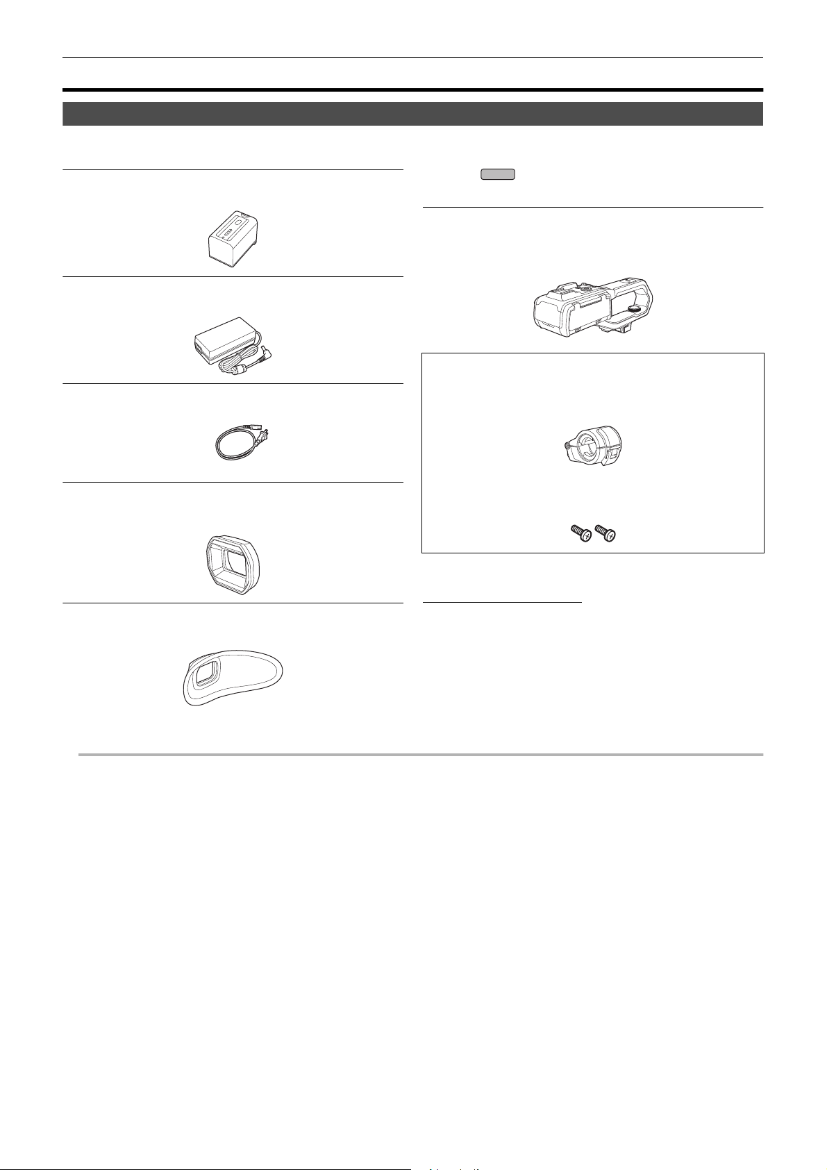
Check the accessories before using this unit.
Product numbers correct as of January 2020. These may be subject to change.
Battery pack (l 28)
AG-VBR59
AC adaptor (l 29)
SAE0011A
AC cable (l 29)
≥For AC adaptor
K2CA2YY00259
∫ For the
The following accessories are also supplied.
Handle unit (l 33)
VW-HU1
≥To purchase as a supplied accessory, use part number
when ordering.
1AC2HCX2500Z
Microphone holder (l 33)
≥The microphone holder mounting screws are supplied with the
microphone holder.
X2000
1KC1VWHU1PPK
Microphone holder mounting screws (l 33)
Lens hood (l 31)
DVYE1189Z
≥Pre-attached to the main unit.
Eye cup (l 32)
DVZE1040Z
≥ Appropriately discard the AC cable cap (if attached) and packing materials after taking the product out.
1PP1HCX2500Z
≥Length 12 mm (0.47q) (×2)
(For U.S.A. only)
If accessories are lost, customers can visit us at
http://shop.panasonic.com/support
for further information about obtaining replacement parts.
- 15 -
Page 16

Chapter 1 Overview — Accessories/Optional accessories
X2000
X1500
Optional accessories
Some optional accessories may not be available in some countries.
Accessory No. Figure Description
AG-MC200G
VW-VMS10PP Stereo microphone
AG-BRD50 Battery charger
VW-VBD58 Battery pack
AG-VBR59 Battery pack
VW-LED1PP LED video light
*
Unidirectional microphone
VW-HU1 Handle unit
* Handle unit ( supplied, optional (VW-HU1)) required.
(For U.S.A. only)
To order optional accessories please visit http://shop.panasonic.com
or your local Photo Specialty Dealer.
NOTE:
Accessories and/or model numbers may vary by country. Please consult your local dealer.
Product numbers correct as of January 2020. These may be subject to change.
- 16 -
Page 17

Chapter 1 Overview — When turning on the power for the first time
NOTE
NOTE
ヌパホパパ
ホ
ハハ
When turning on the power for the first time
The time zone, date, and time are not set when the unit is shipped.
[TIME ZONE] is displayed in the LCD monitor when the power is turned on for the first time.
Follow the guidance and make the settings in the order of [TIME ZONE] and then [CLOCK SETTING].
≥ You can do these operations either with the multidial or by touching the LCD monitor.
[TIME ZONE]
Set the time difference from the Greenwich Mean Time.
A [TIME ZONE]
1 Set the time difference.
2 Select [SET].
Once the setting for [TIME ZONE] is completed, the [CLOCK SETTING] screen is displayed.
0 The setting for the date/time of the main unit changes together with the time zone settings.
0 This can also be set with the [OTHERS] menu → [CLOCK] → [TIME ZONE].
[CLOCK SETTING]
Set the year, month, date, and time.
A [CLOCK SETTING]
B 0 : 0 JAN. 1. 2020
1 Set the year, month, date, and time.
The year can be set between 2018 and 2037.
2 Select [SET].
Once the setting is complete, the camera image screen is displayed.
0 This can also be set with the [OTHERS] menu → [CLOCK] → [CLOCK SETTING].
- 17 -
Page 18

Chapter 1 Overview — What you can do with this unit
X2000
X2000
X2000
What you can do with this unit
Recording to the memory card
Recording in following types is possible.
≥ MOV recording (UHD and FHD recording)
≥ MP4 recording (UHD and FHD recording)
≥ AVCHD recording
≥ Simultaneous recording
≥ Relay recording
≥ Interval recording
≥ Background recording
≥ Pre-recording
Linking to external devices
Connecting to TV/monitor
Connect to a TV/monitor and output images.
≥ When using , use a BNC cable (<SDI OUT> terminal) to connect a TV/monitor.
A HDMI cable
B (For the )
BNC cable (<SDI OUT> terminal)
C TV/Monitor
≥ Use a commercially-available High Speed HDMI cable. If possible, we recommend using a cable with a length of 3 m (approx. 9.8 feet) or less.
≥ (For the )
Use a commercially-available 5C-FB or equivalent double-shielded cable for the BNC cable.
When using a DVI converter, etc., to connect an HDMI cable to this unit, make sure that you connect last to the <HDMI> terminal on this unit.
Connecting first to the <HDMI> terminal on this unit may cause a malfunction.
Card reader mode
Data (files) for performing nonlinear editing on a computer are transferred.
≥ The unit supports USB2.0.
A Memory card
B USB2.0 cable
C Computer
*1 Memory cards are optionally available. They are not supplied with the unit.
*2 A USB2.0 cable is not supplied with the unit.
Use a commercially-available generic USB cable conforming to USB2.0. If possible, we recommend using a cable with a length of 1.5 m (approx. 4.9 feet) or
less.
The unit does not offer a bus-powered function.
*1
*2
- 18 -
Page 19

Chapter 1 Overview — What you can do with this unit
Connecting to the network
This unit is equipped with wireless LAN. It can connect to wireless LAN devices via a network.
Available functions
When the unit is connected to a network, the following functions are available.
∫ Connecting to HC ROP app
You can remotely control this unit with the HC ROP app by connecting this unit with an iPhone/iPad or Android terminal via wireless LAN.
≥ Checking camera status
≥ Camera remote control (focus, zoom, image quality settings, recording control such as start/end recording, and time code/user bits settings)
≥ Menu Operations
≥ Starting and stopping streaming (when the function is assigned to the USER button)
The unit supports the multi camera function, with which a camera selected from up to 8 cameras is remotely controlled from a single device.
For details about operation of the HC ROP app, refer to the online help for the app.
∫ Streaming function
You can perform streaming of audio and video currently shot with the unit over a network (wireless LAN).
- 19 -
Page 20

Chapter 2 Description of Parts
This chapter describes the names, functions, and operations of parts on the unit.
Page 21

Main unit
21 3 4 5
13 14 15
21
22
16
6
1211 17
23
24252627282930
8
7
10
9
201918
Chapter 2 Description of Parts — Main unit
The illustrations in this document show the handle unit ( supplied, optional) removed.
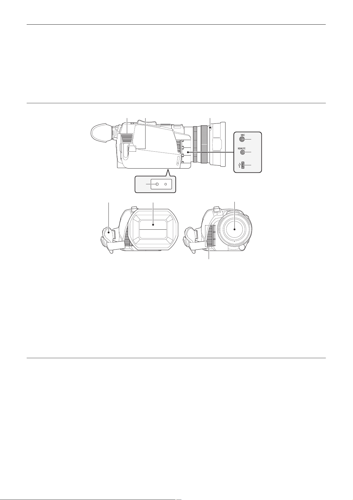
1
Lens hood (l 31)
2
Lens cover switching lever (l 32)
Opens/closes the lens cover.
3
Focus ring (l 111)
When the <FOCUS A/M/¶> button is pressed to set to manual focus
mode ([MF]) you can focus manually.
4
Rear ring (l 108, 110, 118)
You can manually perform zoom operations, adjust the iris (the lens
stop), and adjust the AE level (exposure compensation).
≥ You can switch the function to be adjusted by setting with the menu,
pressing the USER button assigned to [REAR RING], or touching
the USER button icon.
5
<ND FILTER> switch (l 111)
Selects the ND filter to suit the illumination of the subject.
<1/64>: Reduces the amount of light entering the MOS sensor to 1/64.
<1/16>: Reduces the amount of light entering the MOS sensor to 1/16.
<1/4>: Reduces the amount of light entering the MOS sensor to 1/4.
<CLR>: Does not use the ND filter.
6
<FOCUS A/M/¶> button (l 111)
Select the focus function.
[AF] and [MF] switch each time you press the button. The focal point
goes to infinity after you press and hold the button, and then the
manual focus mode is engaged.
[AF]: Changes to the auto focus mode. The auto focus mode adjusts
the focus automatically.
[MF]: Changes to the manual focus mode. Control the focus ring
manually to adjust the focus.
7
Card slot 1 (l 41)
A slot for the memory card.
8
Card 1 access lamp (l 41)
Indicates the access status for recording and playback of the memory
card inserted in card slot 1.
9
Card slot 2 (l 41)
A slot for the memory card.
10
Card 2 access lamp (l 41)
Indicates the access status for recording and playback of the memory
card inserted in card slot 2.
11
Built-in speaker
Outputs audio during playback.
Audio is not output from the built-in speaker when headphones are
connected to the headphone terminal.
12
<SLOT SEL> button
Selects the card slot to record to or play back from.
13
<USER1> button (l 50, 141)
Used as a USER button (USER1).
≥ [LEVEL GAUGE] is allocated at the time of purchase.
Switches display/hide of level gauge.
X2000 X1500
14
15
16
17
18
19
20
21
22
23
24
<USER2> button (l 50, 109)
Used as a USER button (USER2).
≥ [BACKLIGHT] is allocated at the time of purchase.
Switches enable/disable of the auto iris control function for backlight
compensation.
<O.I.S.>/<USER3> button (l 50, 138)
Switches enable/disable of the optical image stabilizer function.
This is also used as the USER button (USER3).
<THUMBNAIL> button (l 146)
Press the button to switch between the camera image screen and the
thumbnail screen.
<DISP/MODE CHK> button (l 165)
Switches display/hide of information other than the time counter, t ime
stamp, zebra pattern, and marker.
Press and hold the button to display information about the settings of
the various shooting functions and information such as a list of the
functions assigned to the USER button. Each press of the button
switches the information page in order.
Diopter adjustment dial (l 54)
Adjusts the diopter scale so that the viewfinder screen can be viewed
clearly.
Eyepiece
Do not leave the eyepiece pointed toward the sun. Doing so might
damage the devices inside.
Eye cup (l 32)
Power button (l 37)
Press the button to switch the power on/off.
<WHITE BAL> button (l 114)
Selects the method for adjustment of the white balance.
Each time you press the button, the white balance switches in the
order “Preset”, [Ach], [Bch].
“Preset”: Adjusts the white balance to the preset value. Each time you
either press the USER button assigned to [AWB] or touch the USER
button icon, the setting changes in the order [P 3200K], [P 5600K],
“VAR” (screen display example: [V 3200K]).
[Ach]/[Bch]: Selects when using the stored value for the adjustment of
the white balance.
<AE LEVEL>/<USER4> button (l 50, 110)
Switches enable/disable of the AE level function.
Set the target value of the AE level in the [SCENE FILE] menu →
[AE LEVEL EFFECT].
This is also used as the USER button (USER4).
<AUTO/MANU> switch (l 104)
Selects the method to adjust the focus, gain, iris, white balance, and
shutter speed at shooting.
<AUTO>: Adjusts automatically. (Auto mode)
<MANU>: Adjusts manually. (Manual mode)
- 21 -
Page 22
Chapter 2 Description of Parts — Main unit
31 33
37
32
34
35
36
3938
40
41
25
<SHUTTER> button (l 112)
Switches the shutter mode.
26
<GAIN> button (l 109)
Selects the method for adjusting screen brightness.
27
<IRIS> button (l 108)
Selects the method for adjustment of the lens stop.
28
<MENU> button (l 60)
Displays the menu. Pressing the <MENU> button while the menu is
displayed closes the menu.
Press the button while the thumbnail screen is displayed to display the
operation screen of the thumbnail menu, and clips can be deleted.
29
<EXIT> button
Returns to one level higher when the menu is displayed. Pressing the
<EXIT> button without confirming the setting value will not reflect the
change in the setting.
30
Multidial (l 143)
Moves, selects, and sets the menu while the menu is displayed.
Use the multidial to also operate thumbnails, select the multi manual
function and select/set the various operation icons.
31
Fan inlet
Fan inlet for cooling fan. Do not block this while the unit is being used.
32
Wireless LAN Transmitter
33
Lens hood release button (l 31)
34
<MIC> terminal (l 36, 125)
Connect an external microphone (stereo mini jack).
35
<REMOTE> terminal
Connects the remote control unit (commercially-available) to control
some functions remotely.
36
USB terminal (l 170)
Connect to a computer with the USB2.0 cable to transfer data.
37
Tripod mounting holes (l 36)
Attach the tripod. (bottom)
≥ Mounting hole size
j 1/4-20 UNC (screw length 5.5 mm (0.22q) or shorter)
≥ Attaching a tripod with a screw length of 5.5 mm (0.22q) or more
may damage the unit.
38
Grip belt (l 31)
39
Lens cover (l 32)
40
Lens
41
Fan outlet
Fan outlet for cooling fan. Do not block this while the unit is being
used.
- 22 -
Page 23

Chapter 2 Description of Parts — Main unit
52
4342 45 46
44
47
48
49
50
51
X2000
42
Status indicator (l 37)
Illuminates when power is on.
43
Battery release lever (l 28)
Used when removing the battery from the main unit.
44
Battery mounting section (l 28)
Attaches a battery.
45
Viewfinder (l 54)
46
REC button (on the grip) (l 104)
Starts or stops the recording.
It is possible to directly record from the thumbnail mode.
47
<HDMI> terminal (l 169)
A terminal to output video signal by connecting a monitor, etc.
48
Headphones terminal
Connects audio monitoring headphones.
49
Charging lamp (l 29)
Illuminates when the battery is charging.
50
<DC IN 12V> terminal (l 29)
Connects the supplied AC adaptor and supplies an external power.
51
(For the )
<SDI OUT> terminal (l 169)
A terminal to output SDI signal by connecting a monitor, etc.
52
LCD monitor (l 53)
X2000
53
Built-in microphone (l 125)
This is the built-in stereo microphone <L>/<R>.
54
Accessory shoe (on the main unit)
Attach a video light, etc.
55
Zoom lever (on the grip) (l 118, 153)
Adjusts the zoom of an image.
<T>: Zooms in the image.
<W>: Zooms out the image.
≥ Adjust the volume when playing back clips.
56
Handle unit mounting section (l 33)
57
<USER5> button (l 50, 105)
Used as a USER button (USER5).
≥ [REC CHECK] is set at the time of purchase.
Automatically plays back the last approximately 3 seconds of the
previously shot clip.
53 54 5655 57
- 23 -
Page 24
Chapter 2 Description of Parts — Handle unit ([X2000] supplied, [X1500] optional: VW-HU1)
Handle unit ([X2000] supplied, [X1500] optional: VW-HU1)
1
8
9
1110
15 1214 13
A With a microphone holder attached
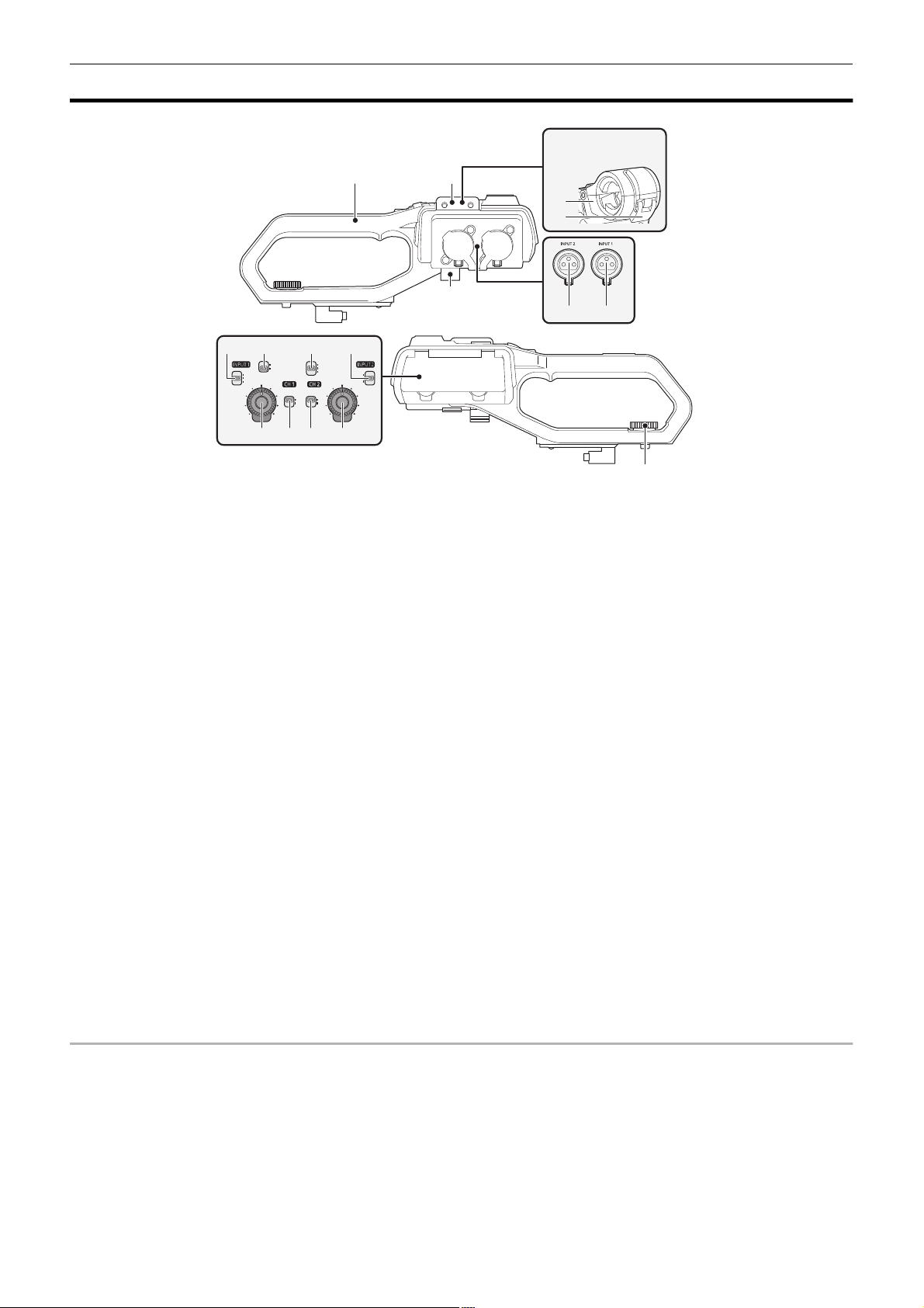
1
Handle
2
Microphone holder mounting section (l 33)
Attaches the supplied microphone holder with the microphone holder
mounting screws.
3
Microphone holder (l 33, 35)
Secures the external microphone in place.
4
Buckle (l 33, 35)
Used to open and close the microphone holder.
5
<INPUT 1> terminal (XLR, 3-pin) (l 35, 125)
Connects an audio equipment or an external microphone.
6
<INPUT 2> terminal (XLR, 3-pin) (l 35, 125)
Connects an audio equipment or an external microphone.
7
Microphone cable clamp (l 35)
Fixes the external microphone cable.
8
<INPUT1> switch (l 126)
Switches audio input signals connected to the <INPUT 1> terminal.
<LINE>: Select when audio equipment is connected by the line input.
<MIC>: Select when the external microphone is connected.
<i48V>: Select when the external microphone is connected and the
microphone needs a power supply.
9
CH1 SELECT switch (l 125)
Selects the audio to be recorded on audio channel 1.
<INT/MIC (L)>: Records left audio from the built-in microphone or
<MIC> terminal.
<INPUT1>: Records input signals from the <INPUT 1> terminal.
10
CH2 SELECT switch (l 125)
Selects the audio to be recorded on audio channel 2.
<INT/MIC (R)>: Records right audio from the built-in microphone or
<MIC> terminal.
<INPUT1>: Records input signals from the <INPUT 1> terminal.
<INPUT2>: Records input signals from the <INPUT 2> terminal.
2
3
4
7
6 5
16
11
<INPUT2> switch (l 126)
Switches audio input signals connected to the <INPUT 2> terminal.
<LINE>: Select when audio equipment is connected by the line input.
<MIC>: Select when the external microphone is connected.
<i48V>: Select when the external microphone is connected and the
microphone needs a power supply.
12
<AUDIO LEVEL CH2> dial (l 126)
Adjust the recording level of audio channel 2.
13
<CH2> switch (l 126)
Selects how the recording level for audio channel 2 is adjusted.
<AUTO>: Adjusted automatically.
<MANU>: Adjusted manually with the <AUDIO LEVEL CH2> dial.
14
<CH1> switch (l 126)
Selects how the recording level for audio channel 1 is adjusted.
<AUTO>: Adjusted automatically.
<MANU>: Adjusted manually with the <AUDIO LEVEL CH1> dial.
15
<AUDIO LEVEL CH1> dial (l 126)
Adjust the recording level of audio channel 1.
16
Handle unit mounting screw (l 33)
Secures the handle unit to the main unit.
- 24 -
Page 25

Chapter 2 Description of Parts — Handle unit ([X2000] supplied, [X1500] optional: VW-HU1)
26 25 24
2120 22 23
17 18
19
17
Light cover
≥ Keep the Light cover out of reach of children to prevent swallowing.
18
Built-in LED light (l 120)
19
Tally lamp (l 55)
Illuminates when the recording is started. Flashes when the battery
level becomes low.
Whether or not to illuminate the lamp can be set in the menu.
20
Accessory shoe (on the handle)
Attach a video light, etc.
21
<LIGHT> switch (l 120)
Switches the built-in LED light on/off.
22
Hold lever
Disables the REC button (on the handle) when switched to <HOLD>.
23
REC button (on the handle) (l 104)
Starts or stops the recording.
24
Accessory mounting hole
Accessories can be attached.
≥ Mounting hole size
j 1/4-20 UNC (screw length 5.5 mm (0.22q) or shorter)
25
Zoom lever (on the handle) (l 118)
Adjust the zoom of an image.
<T>: Zooms in the image.
<W>: Zooms out the image.
≥ The zoom speed is controlled with this lever in a way different from
the way it is controlled with the zoom lever (on the grip).
26
Light dimmer dial (l 120)
Adjusts the brightness of the built-in LED light.
Turn to <i> to brighten, turn to <j> to dim.
- 25 -
Page 26

Chapter 2 Description of Parts — Basic operation
NOTE
NOTE
Basic operation
Multidial operation
Operate the multidial on the main unit by turning it in vertical direction or pushing it.
≥ Turning the multidial in vertical direction will move the cursor.
≥ Pressing the multidial will select or confirm the item with cursor.
≥ Values of the menu or the pages of the thumbnail screen can be changed continuously by pressing and turning the multidial vertically to fix the setting.
0 For details about operating the menu, refer to “When operating with the multidial”. (l 62)
Touch operation of the LCD monitor
The LCD monitor can be operated by directly touching with a finger.
Do not touch the LCD monitor with a pointed hard object such as a ball point pen.
∫ Touching
An operation to press and release the LCD monitor. An item or icon can be selected, or an item can be executed.
≥ To select an icon, touch the center of the icon.
≥ It will not operate while touching a different location of the LCD monitor.
∫ Sliding
An operation to move a finger while touching the LCD monitor. Playback operation such as the skip playback or direct playback, etc. can be performed.
∫ Touching and holding
An operation to keep on pressing, then releasing the LCD monitor. Values of the menu or the pages of the thumbnail screen can be changed
continuously.
0 For details about operating the menu, refer to “When operating by touching the LCD monitor”. (l 63)
- 26 -
Page 27

Chapter 3 Preparation
Before you use the unit, attach the battery following the procedures in this chapter. The attaching of accessories is also described in this chapter.
Page 28

Chapter 3 Preparation — Power supply
Power supply
A battery or the supplied AC adaptor can be used as the power supply for the unit.
≥ The unit is compatible to following batteries. (As of January 2020)
j AG-VBR59 (supplied/optional, supports quick charging)
j VW-VBD58 (optional)
≥ AG-VBR59 supports quick charging. Use a battery charger (AG-BRD50: optional) to perform quick charging.
Attaching and removing the battery
¥ Press the power button to turn off the unit. (l 37)
Attaching the battery
1 Push the battery against the battery mounting section on the main unit and
slide forward to attach.
Press in the battery until it clicks and gets locked.
A Battery mounting section
Removing the battery
Be sure to hold down the power button until the status indicator goes off. Then remove the
battery while supporting the unit to prevent it from dropping.
B Status indicator
Move the battery release lever in the direction indicated by
the arrow and remove the battery when unlocked.
- 28 -
Page 29

Chapter 3 Preparation — Power supply
NOTE
Charging the battery
The battery is not charged at the time of purchase. Use only after charging sufficiently.
It is recommended that you have one extra battery.
≥ It is recommended to perform charging of the battery in a location with ambient temperature of 10 °C to 30 °C (50 oF to 86 oF) (same for the battery
temperature).
≥ Use the supplied AC adaptor. Do not use the AC adaptor of another device.
≥ The supplied AC cable is dedicated for this unit. Do not use with any other device. Also, do not use AC cable from other device on this unit.
≥ The battery is not charged when the power is on.
1 Connect the AC cable to the AC adaptor and the AC outlet.
≥ Insert the plugs as far as they will go.
2 Connect the AC adaptor to the <DC IN 12V> terminal.
≥ As the charging lamp lights up green, charging starts. It will turn off
when the charging is completed.
≥ If the charging lamp flashes, refer to page 12.
≥ The DC plug of the AC adaptor, depending on its angle, may block
your view of the charging lamp. To check the charging lamp status,
adjust the angle of the DC plug.
∫ Connecting to the AC outlet
It is possible to use this unit with power supplied from the AC outlet by turning on the unit with the AC adaptor connected.
Even when you use the AC adaptor for recording images, keep the battery connected.
This allows you to continue the recording even if a power failure occurs or the AC adaptor is unplugged from the AC outlet by accident.
≥ The AC adaptor is in the standby condition when the mains plug is connected. The primary circuit is always “live” as long as the AC adaptor is
connected to an electrical outlet.
0 Do not use any other AC adaptors except the supplied one.
0 We recommend using Panasonic batteries (l 28).
0 If you use other batteries, we cannot guarantee the quality of this product.
0 Do not heat or expose to flame.
0 Do not leave the battery(ies) in a car exposed to direct sunlight for a long period of time with doors and windows closed.
0 Do not expose to low air pressure at high altitudes.
0 Do not expose to extremely low air pressure, as this may result in explosions or leakage of flammable liquids and gases.
- 29 -
Page 30

Chapter 3 Preparation — Power supply
NOTE
NOTE
X1500
X2000
ヤラユヤレヤラユヤレ
ヒパパ
テ
パ
1 2
Standard charging time and recordable time
Battery parts number
AG-VBR59 (supplied/optional) 7.28 V/5900 mAh Approx. 5 h 30 min [59.94Hz] Approx. 5 h 20 min Approx. 4 h 35 min
VW-VBD58 (optional) 7.2 V/5800 mAh Approx. 5 h 15 min [59.94Hz] Approx. 5 h 15 min Approx. 4 h 30 min
Voltage/capacity
(minimum)
Charging time for
main unit
[FREQUENCY]
[50.00Hz] Approx. 5 h 40 min Approx. 4 h 50 min
[50.00Hz] Approx. 5 h 35 min Approx. 4 h 45 min
Continuous recordable time
≥ “h” is an abbreviation for hour and “min” for minute.
≥ The charging time is the time when the operating ambient temperature is 25 °C (77 oF) and operating relative humidity is 60%. At other temperature and
humidity the charging time may take longer.
≥ Continuous recordable time is the time when the unit is used fulfilling all of the following conditions. If you use the unit in other conditions, continuous
recordable time will shorten.
j When set to the factory default menu settings ([FILE FORMAT] is [MOV] and [REC FORMAT] is [2160-59.94p/HEVC LongGOP 200M]/[2160-50.00p/
HEVC LongGOP 200M])
j When the LCD monitor is used and cable is not connected to the external input/output terminal
¥ The charging time is the time to charge when the charging capacity of the battery is used up. The charging time or the continuous
recordable time differs depending on the use condition such as high or low temperature.
∫ Batteries that support quick charging
For quick charging of a battery (AG-VBR59: supplied/optional), use a battery charger (AG-BRD50: optional).
0 Battery is warm after using or after charging, but this is not a malfunction.
Checking the remaining battery level
The remaining battery level can be checked with the power status display on the LCD monitor or the indicator on the supplied battery.
Checking the remaining battery level with the LCD monitor
The battery status display will change as → → → → → while the remaining battery level gets lower. It will flash in red
when the remaining battery level is zero.
0 The power status display may not be displayed depending on the setting in the menu.
0 Repair or copy of the clip, or update of the firmware is not possible when it is flashing in red.
Checking the remaining battery level with the battery
≥ The remaining battery level can be checked with the indicator display by pressing the <CHECK> button on the battery when it is not charging.
j The remaining battery level is a rough indication.
j The indicator will not illuminate even if the <CHECK> button is pressed when the remaining battery level is zero. Charge the battery.
≥ The progress of the charging is notified by the flashing position of the indicator while the battery is charging.
Once the charging is completed, the indicator turns off.
1
Indicator
2
<CHECK> button
∫ Display of the indicator
≥ The color and illuminate/flashing status of the indicator indicated by the icon in the table are as follows.
j : Flashing in green
j : Illuminated in green
j : Off
Indicator display
When checking the remaining battery level Charging
Remaining battery level/charging progress
0% to 25%
25% to 50%
50% to 75%
75% to 100%
≥ Display of the indicator is a rough indication. If the battery is attached to the unit or the battery charger (optional), check the remaining level on the
device the battery is attached to. The remaining level may differ from the one displayed with the indicator on the battery.
- 30 -
Page 31

Chapter 3 Preparation — Attaching accessories
22
44
11
33
Attaching accessories
Adjusting the grip belt
≥ Adjust the grip belt so that it fits the size of your hand.
≥ If the buckle is difficult to tighten, move the pad backward and tighten the buckle again.
A Button
B Buckle
C Pad
1 Undo the button of the grip belt.
2 Open the buckle section.
3 Pull the end of the belt.
4 Do up the button of the grip belt.
Attaching the lens hood
Removing
A Lens hood release button
1 While pressing the lens hood release button, turn the lens hood in the direction of the arrow to remove it.
Attaching
B Mounting mark
1 Insert the lens hood into the unit.
≥ Align the mounting marks on the lens hood and unit.
2 Turn the lens hood clockwise.
≥ Turn until the lens clicks and locks into place.
- 31 -
Page 32

Chapter 3 Preparation — Attaching accessories
NOTE
Opening and closing the lens cover
Use the lens cover switching lever to open and close the lens cover.
Open the lens cover when shooting.
When not using the unit, close the lens cover in order to protect the lens.
0 Do not press the lens cover with force. Doing so may damage the lens and lens cover.
0 The lens cover may not open and close or the lens hood may not attach depending on the various filters and MC protectors mounted to the front lens of
the unit.
Attaching the eye cup
1 Attach the eye cup by aligning the groove on the mounting part of the eye cup with the inner ridge of the eye cup.
The illustration below is an example of attaching the eye cup to use it with your right eye.
If you rotate the eye cup to the left by 180° before attaching it, you can use it with your left eye.
A Groove
B Ridge
- 32 -
Page 33

Chapter 3 Preparation — Attaching accessories
Attaching the handle unit ([X2000] supplied, [X1500] optional)
¥ Press the power button to turn off the unit. (l 37)
1 Open the microphone holder.
Open buckle 1, and detach fitting 2 from hook 3.
2 Attach the microphone holder to the microphone holder mounting section on the
handle unit.
≥ Attach using a commercially-available screwdriver.
≥ There will be some rubbing noises with the rubber when screwing in the microphone holder
mounting screws, but please ensure they are done up tightly.
1 Microphone holder
2 Microphone holder mounting screws
3 Push the handle unit into the handle unit mounting section on the camera.
Match the positions of mounting mark A on the handle unit and mounting mark B on the
camera when pushing in.
4 Slide the handle unit in the direction indicated by the arrow.
Slide up to mounting mark C.
- 33 -
Page 34

Chapter 3 Preparation — Attaching accessories
NOTE
5 While pressing the handle unit mounting screw down, turn it in the direction
indicated by arrow 2 until it stops.
∫ How to remove
Remove by doing the steps for attaching in reverse.
0 Keep the microphone holder mounting screws out of reach of children to prevent swallowing.
- 34 -
Page 35

Chapter 3 Preparation — Attaching accessories
NOTE
Attaching the external microphone
∫ Attaching an external microphone to the <INPUT 1>/<INPUT 2> terminals
When the handle unit ( supplied, optional) is attached to the unit, you can attach an external microphone such as a unidirectional
microphone AG-MC200G (optional) that is compatible with XLR terminals to the handle.
X2000 X1500
1 Open the microphone holder.
2 Attach the external microphone to the microphone holder, then close the buckle to
secure the external microphone.
Attach the fitting to the hook and close the buckle in the direction indicated by the arrow.
3 Connect the microphone cable to the <INPUT 1> terminal A.
4 Attach the microphone cable to the microphone cable clamp B.
5 Switch the <INPUT1> switch to match the microphone to be connected.
0 When removing the microphone cable from the <INPUT 1> terminal, remove by lifting levers C.
- 35 -
Page 36

Chapter 3 Preparation — Attaching accessories
NOTE
∫ Attaching an external microphone to the <MIC> terminal
You can attach an external microphone, such as a Stereo Microphone VW-VMS10PP (optional), etc., that is compatible with the stereo mini jack.
1 Attach the external microphone to the accessory shoe A.
≥ For details about how to attach the external microphone, refer to the operating
instructions for the external microphone.
2 Connect the microphone cable to the <MIC> terminal.
Attaching a tripod
The tripod mounting holes accept 1/4-20 UNC screws.
0 Use a tripod in safe locations.
0 The depth of the tripod mounting holes is 5.5 mm (0.22q). Do not over-tighten the tripod screw when attaching the unit to a tripod.
0 Attaching a tripod with a screw length of 5.5 mm (0.22q) or more may damage the unit.
- 36 -
Page 37

Chapter 3 Preparation — Turning on/off the power
NOTE
Turning on/off the power
Turning the unit on and off with the power button
1 Open the LCD monitor and press the power button to turn on the unit.
A The status indicator lights on.
∫ To turn off the unit
Hold down the power button until the status indicator goes off.
0 The [TIME ZONE] screen is displayed when the power is turned on for the first time. (l 17)
Set the time zone, date, and time.
0 The built-in battery (rechargeable battery) will discharge. The setting for date/time may be initialized when the unit is not turned on for approximately
6 months.
Set the date/time again after charging the built-in battery. (l 38)
Turning the unit on and off with the LCD monitor/viewfinder
Opening the LCD monitor or extending the viewfinder turns on the unit. Closing the LCD monitor/viewfinder turns off the unit.
During normal use, you may find it convenient to turn the unit on/off using the LCD monitor or viewfinder.
≥ The unit will not turn off unless the LCD monitor is closed and the viewfinder is retracted.
≥ The unit will not turn off during recording or while connected to a network even if the LCD monitor is closed and the viewfinder is retracted.
≥ In the following cases, opening the LCD monitor or extending the viewfinder does not turn on the unit. Press the power button to turn on the unit.
j When the unit is originally purchased
j When you have turned off the unit using the power button
Charging the built-in battery
The date/time set in the unit is maintained by the built-in battery.
If this unit is left without turning the power on, and then when you turn the power on and [BACKUP BATT EMPTY] is displayed on the viewfinder and LCD
monitor for approximately 5 seconds, the built-in battery is exhausted.
The date of the internal clock of the unit resets to January 1, 2020 if the built-in battery is exhausted.
Charge the built-in battery with the following procedure.
1 Press the power button to turn off the unit.
2 Connect a fully charged battery or the AC adaptor to the unit.
For details about the connection of the battery or AC adaptor, refer to “Power supply”. (l 28)
3 Leave the unit for approximately 24 hours.
The built-in battery will be charged.
The built-in battery recharges even when the power is on.
Check the date/time setting and the time code after charging. If [INTERNAL CLOCK HAS RESET] [<PLEASE SET TO CORRECT TIME>] is
displayed on the STATUS screen of the mode check, set the date/time of the internal clock. (l 38)
4 Press the power button to turn on the power, and confirm that [BACKUP BATT EMPTY] is not displayed on the LCD monitor.
If [BACKUP BATT EMPTY] is still displayed after charging, the built-in battery needs to be replaced. Consult your dealer.
- 37 -
Page 38

Chapter 3 Preparation — Setting the date/time of the internal clock
NOTE
Setting the date/time of the internal clock
The date/time/time zone are recorded as meta data in the clip while shooting.
This will affect the management of recorded clips, so always check and set the date/time and time zone before using the unit for the first time.
Do not change the setting of the date/time and time zone while shooting.
1 Press the <MENU> button.
The menu is displayed.
2 Select the [OTHERS] menu → [CLOCK] → [TIME ZONE], and set the time difference from Greenwich Mean Time.
3 Select the [OTHERS] menu → [CLOCK] → [CLOCK SETTING], and set the year, month, date, and time.
∫ Time zone table
Time difference Region Time difference Region
i0:00 Greenwich i0:30
j0:30 i1:00 Central Europe
j1:00 Azores i1:30
j1:30 i2:00 Eastern Europe
j2:00 Mid-Atlantic i2:30
j2:30 i3:00 Moscow
j3:00 Buenos Aires i3:30 Tehran
j3:30 Newfoundland i4:00 Abu Dhabi
j4:00 Halifax i4:30 Kabul
j4:30 Caracas i5:00 Islamabad
j5:00 New York i5:30 Mumbai
j5:30 i6:00 Dakar
j6:00 Chicago i6:30 Yangon
j6:30 i7:00 Bangkok
j7:00 Denver i7:30
j7:30 i8:00 Beijing
j8:00 Los Angeles i8:30
j8:30 i9:00 Tokyo
j9:00 Alaska i9:30 Darwin
j9:30 Marquesas Islands i10:00 Guam
j10:00 Hawaii i10:30 Lord Howe Island
j10:30 i11:00 Solomon Islands
j11:00 Midway Islands i11:30
j11:30 i12:00 New Zealand
j12:00 Kwajalein Atoll i12:45 Chatham Islands
i1
3:00 Phoenix Islands
0 Accuracy of the clock is approximately n30 seconds per month. Check and reset the time when accurate time is required.
0 Due to the format specifications, with AVCHD format, the following time difference conversions are made for recording with the clip.
Time difference set in [TIME ZONE] Time difference recorded with AVCHD clips
i12:45 i12:30
- 38 -
Page 39

Chapter 3 Preparation — Preparing the memory card
Preparing the memory card
Memory cards supported by the unit (As of January 2020)
Type of the memory card Recording capacity
SDHC memory card 4 GB to 32 GB
SDXC memory card 48 GB to 128 GB
≥ Operation is not guaranteed for any memory cards other than the above.
≥ Panasonic memory cards are recommended.
≥ The following memory cards cannot be used because they do not comply with the SD standards.
j A memory card with 4 GB or more without the SDHC logo
j A memory card with 48 GB or more without the SDXC logo
≥ This unit supports the following memory cards:
j SDHC/SDXC memory cards that conform with the UHS-I UHS Speed Class 3 standard
≥ Keep the memory card out of reach of children to prevent swallowing.
Speed Class during shooting
The memory card to use differs depending on the file format and the recording format.
Use memory cards compatible with the Speed Class or UHS Speed Class.
The recording may stop suddenly when a memory card not compatible with the required Speed Class is used.
Speed Class and UHS Speed Class are the speed specification regarding continuous writing. Check the display on the label and other information on the
memory card.
File format
MOV/MP4
AVCHD All ≥ SD card with Speed Class 4 or better
When the file format is MOV or MP4
≥ SDXC memory cards can be used. SDHC memory cards cannot be used.
Recording bit rate or recording
function
200 Mbps, 150 Mbps, 100 Mbps,
Super slow recording
72 Mbps, 50 Mbps ≥ SDXC memory card with Speed Class 10
Supported memory cards and Speed
Classes
≥ SDXC memory card with UHS Speed Class 3
Example of card display
- 39 -
Page 40

Chapter 3 Preparation — Preparing the memory card
Preventing unintentional erasing
Writing, erasing and formatting data is prohibited by setting the write-protection switch A of the memory card to the LOCK side.
Status of the card access lamp and memory card
Card access lamp Memory card status
Orange (illuminated) Recording target Both loading/writing are permitted. Current recording target.
Green (illuminated) Recording possible Both loading/writing are permitted.
Orange (flashing) Accessing card Loading/writing are currently being performed.
Orange (rapidly flashing) Recognizing memory card The memory card is being recognized.
Error
Green (slowly flashing) No remaining recording capacity No recording capacity left on the memory card. Only loading is possible.
Write-protected The write-protection switch of the memory card is set to the LOCK side.
Recording not possible
Off No memory card inserted A memory card has not been inserted.
Illegal format It is not the correct format. Reformat the card.
Card not supported
During card reader mode The card 1 access lamp/card 2 access lamp turns off when not accessing.
An error has occurred. This will flash even if the memory card is not
inserted when an error has occurred.
It cannot record with the recording format that is currently set. Change the
recording format or use a memory card compatible with the recording
format to record.
This is a card that cannot be used with the unit, such as MMC (Multi Media
Card).
- 40 -
Page 41

Chapter 3 Preparation — Preparing the memory card
NOTE
Inserting/removing the memory card
Inserting the memory card
The memory card to use with the unit should always be formatted on the unit. (l 41)
≥ Formatting the memory card will erase all of the recorded data which cannot be restored.
A Card slot cover
B Label side
C Card slot 1
D Card 1 access lamp
E Card slot 2
F Card 2 access lamp
1 Open the card slot cover.
2 Insert the memory card into the card slot.
≥ Card slot 1 and card slot 2 can each insert one memory card.
≥ With the label facing in the direction indicated in the diagram, push in until there is a click.
Do not force or apply excess force when inserting the memory card.
3 Close the card slot cover.
Removing the memory card
1 Open the card slot cover.
≥ Confirm that the card access lamp is not flashing in orange.
≥ Data is being written/loaded when the card access lamp is flashing in orange, so do not remove the memory card.
2 Press in the memory card further into the main unit and let go.
≥ Pull the memory card straight out when it is released from the card slot.
3 Close the card slot cover.
Cautions when using or storing
≥ Do not touch the connecting terminal section at the rear of the memory card.
≥ Avoid high temperature and humidity.
≥ Avoid water droplets.
≥ Avoid charging with electricity.
Use or store the memory card with the card inserted into the unit and with the slot cover closed.
Formatting the memory card
Before recording with a memory card that is to be used for the first time in this unit, format it.
All data will be deleted when the card is formatted. Save any important data to a computer, etc. (l 170)
≥ When using 2 memory cards, you must format both of the memory cards.
1 Select the [RECORDING] menu → [FORMAT MEDIA] → [SLOT1]/[SLOT2].
2 When the confirmation message is displayed, select [SET].
3 When the completion message is displayed, select [ ].
0 Do not turn this unit off or remove the memory card, while formatting. Do not expose the unit to vibrations or shock.
0 This function can be operated also by touching the LCD monitor.
0 It may take few seconds after closing the completion message until it can record.
Format the cards using this unit. (Do not format using other devices, such as a computer, etc. Doing so may make the cards unusable in
this unit.)
- 41 -
Page 42

Chapter 3 Preparation — Preparing the memory card
NOTE
Recording time of the memory card
≥ Memory cards are only mentioned with their main memory size. The stated times are the approximate recordable times for continuous recording.
≥ If recording for long periods, prepare batteries for 3 or 4 times the period you wish to record for. (l 30)
≥ The recordable time may be reduced if recording with a lot of action is recorded or recording of short clip is repeated.
≥ The recordable times depends on the recording condition or memory card type to be recorded.
≥ For the resolutions, frame rates, and bit rates for [REC FORMAT], refer to page 105.
≥ Refer to page 39 for the memory cards compatible with the different file formats.
When the file format is MOV
Recording format Recording rate
200 Mbps Approx. 40 min Approx. 1 h 20 min
UHD
FHD
≥ “h” is an abbreviation for hour and “min” for minute.
0 With super slow recording, the recording time changes depending on the frame rate of the [REC FORMAT].
0 File is split approximately every 3 hours for the data in MOV format.
These are displayed as separate clips in the thumbnail screen. In addition, the clips recorded across 2 memory cards using the relay recording are
displayed as separate clips.
0 The recording is stopped once when the recording time reaches 10 hours, and recording is automatically resumed after few seconds. Image and audio
during the pause will not be recorded. This includes the case of special recording, such as super slow recording or relay recording.
With super slow recording, the recording time will be shorter than 10 hours.
For the recording time for 1 clip when super slow recording, refer to page 124.
0 In the interval recording, the recording is stopped once when the length of a clip reaches 10 hours, and recording is automatically resumed after few
seconds.
150 Mbps Approx. 55 min Approx. 1 h 50 min
100 Mbps Approx. 1 h 20 min Approx. 2 h 40 min
200 Mbps Approx. 40 min Approx. 1 h 20 min
100 Mbps Approx. 1 h 20 min Approx. 2 h 40 min
50 Mbps Approx. 2 h 40 min Approx. 5 h 20 min
64 GB 128 GB
Recording capacity
- 42 -
Page 43

When the file format is MP4
NOTE
NOTE
Chapter 3 Preparation — Preparing the memory card
Recording format Recording rate
UHD
FHD 50 Mbps Approx. 2 h 40 min Approx. 5 h 20 min
100 Mbps Approx. 1 h 20 min Approx. 2 h 40 min
72 Mbps Approx. 1 h 50 min Approx. 3 h 40 min
64 GB 128 GB
Recording capacity
≥ “h” is an abbreviation for hour and “min” for minute.
0 File is split approximately every 3 hours for the data in MP4 format.
These are displayed as separate clips in the thumbnail screen. In addition, the clips recorded across 2 memory cards using the relay recording are
displayed as separate clips.
0 The recording is stopped once when the recording time reaches 10 hours, and recording is automatically resumed after few seconds. Image and audio
during the pause will not be recorded. This includes the case of special recording, such as relay recording.
0 In the interval recording, the recording is stopped once when the length of a clip reaches 10 hours, and recording is automatically resumed after few
seconds.
When the file format is AVCHD
∫ For SDHC memory card
Recording format Recording rate
PS 25 Mbps Approx. 19 min Approx. 40 min Approx. 1 h 20 min Approx. 2 h 40 min
PH 21 Mbps Approx. 21 min Approx. 46 min Approx. 1 h 30 min Approx. 3 h
HA 17 Mbps Approx. 30 min Approx. 1 h Approx. 2 h Approx. 4 h 10 min
PM 8 Mbps Approx. 1 h Approx. 2 h Approx. 4 h 15 min Approx. 8 h 30 min
4 GB 8 GB 16 GB 32 GB
∫ For SDXC memory card
Recording capacity
Recording format Recording rate
PS 25 Mbps Approx. 5 h 20 min Approx. 11 h
PH 21 Mbps Approx. 6 h Approx. 12 h 30 min
HA 17 Mbps Approx. 8 h 30 min Approx. 17 h
PM 8 Mbps Approx. 17 h 10 min Approx. 35 h
64 GB 128 GB
Recording capacity
≥ “h” is an abbreviation for hour and “min” for minute.
0 File is split approximately every 4 GB for the data in AVCHD format.
These are displayed as one clip in the thumbnail screen. However, the clips recorded across 2 memory cards using the relay recording are displayed as
separate clips.
0 The recording is stopped once when the recording time reaches 10 hours, and recording is automatically resumed after few seconds. Image and audio
during the pause will not be recorded. This includes the case of special recording, such as relay recording.
0 Protection is automatically released on memory cards locked with AVCHD protection such as DVD recorders.
- 43 -
Page 44

Chapter 3 Preparation — Preparing the memory card
NOTE
NOTE
B002
PRIVATE
PANA_GRP
003RCPAM
004YAPAM
BACKUP.TMP
INDEX.DAT
AVCHD
AVCHDTN
BDMV
PANA_EXT
1
2
3
4
5
6
7
8
9
10
001RCQAM
002YCJAM
Handling the recording data
Folder structure example of a memory card
Various important information is contained in the recording data, and it is linked with the folder structure and management files as shown in the figure.
If such information is changed or deleted even partially, an error such as that the data cannot be recognized or the recording becomes impossible may
occur.
1
Volume label of the memory card
2
Video data in MOV format: UHD (3840×2160), 29.97p MOV (audio: LPCM)
3
Video data in MOV format: FHD (1920×1080), 59.94i MOV (audio: LPCM)
4
Video data in MP4 format: UHD (3840×2160), 29.97p MP4 (audio: AAC)
5
Video data in MP4 format: FHD (1920×1080), 59.94p MP4 (audio: AAC)
6
Management file 1
7
Management file 2
8
Thumbnail of video data
9
Video data in AVCHD standard (00000.MTS, etc.)
10
Management folder
0 Do not erase a folder or file on the memory card with a computer. It may make it impossible to load on the unit.
0 If data is recorded to the memory card with a computer, an error may occur such as an inability to recognize or record to the memory card with the unit.
0 The memory card to use with the unit should always be formatted on the unit.
Volume label of the memory card
∫ When the file format is MOV or MP4
The value set in the [RECORDING] menu → [CLIP NAME] is stored in the volume label in the CAM INDEX i NEXT CARD COUNT format when the
memory card is formatted. Once it is stored, [NEXT CARD COUNT] will increase by one. The CARD COUNT that is stored is also used for the CARD
number of the MOV format/MP4 format file name.
0 When recording to the memory card that CAM INDEX i CARD COUNT is not stored in the volume label, the value set in the [RECORDING] menu →
[CLIP NAME] is automatically stored in the volume label, and [NEXT CARD COUNT] will increase by one.
∫ When the file format is AVCHD
“CAM_SD” is stored in the volume label.
- 44 -
Page 45

Chapter 3 Preparation — Preparing the memory card
NOTE
001RAQAM
123456
7
B00 2C010 _200918_E125
.MOV
21 634 5
Folder name of the MOV format/MP4 format video data
The fourth through eighth characters of the folder name differ depending on the setting of the unit.
1
Folder number
001 to 999 (sequential number)
2
Number of pixels
R: 3840×2160
Y: 1920×1080
3
Frame rate
A : 59.94 fps
B : 50.00 fps
C : 29.97 fps
D : 25.00 fps
F : 23.98 fps
4
Video format
P : Progressive recording (MP4, AAC)
Q : Progressive recording (MOV, LPCM)
I : Interlace recording (MP4, AAC)
J : Interlace recording (MOV, LPCM)
5
Fixed values
A
6
Recording setting
M : Standard recording (card slot 1 for simultaneous recording)
T : Simultaneous recording (card slot 2 for simultaneous recording)
7
Recording format information
∫ When the folder name is 001RAQAM
Following video data is saved in the folder.
≥ Number of pixels: 3840×2160
≥ Frame rate: 59.94 fps
≥ Video format: Progressive recording (MOV, LPCM)
File name of the MOV format/MP4 format video data
The format of the file name is as follows.
1
CAM INDEX
One character from upper case A to Z.
≥ An INDEX assigned to each camera. Set with the [RECORDING] menu → [CLIP NAME] → [CAM INDEX].
2
CARD number
001 to 999
≥ This is the number assigned to each memory card. The CARD COUNT stored in the volume label of the memory card is assigned.
3
Clip number
C001 to C999
≥ This is a sequential number assigned to each recording on the memory card. The number returns to C001 when the memory card is formatted.
It will also return to C001 for the one after C999.
The clip number is maintained even when the folder is split or when the clip is deleted.
4
Date
Last 2 digits of year i 2 digits of month i 2 digits of date when the recording is started.
5
Hashtag generated from the serial number
4-digit number or alphabet
6
File format
[.MOV] or [.MP4]
0 The clip name of the card slot 2 will be the same as the clip name of the card slot 1 for the simultaneous recording.
- 45 -
Page 46

Chapter 3 Preparation — Preparing the memory card
About the number of clips that can be recorded to a memory card
File format Number of clips
MOV Approx. 4000
MP4
AVCHD Approx. 3900
≥ When multiple file formats are recorded to a single memory card, the number will be less than that shown above.
∫ About MOV/MP4 folders
The maximum number of folder and the folder number is 999. The recording is prohibited when it reaches 999 even if number in between is open.
≥ The upper limit for the number of clips that can be recorded in a single folder is 999. Once it reaches 999, a folder with sequential number added is
newly created.
Also, a folder with sequential number added is newly created when the folder name is changed by changing the setting of the unit.
The folder number will return to 001 when the memory card is formatted.
∫ About AVCHD playlists
When recording with AVCHD, playlists are generated. The upper limit for the number of clips that can be recorded in a single playlist is 99.
≥ A new playlist is generated in the following cases.
j When the [REC FORMAT] is changed for recording
j When recording with interval recording
j When a memory card that has been used in this unit is recorded to with another device
j When the total recording time in a single playlist reaches 11 hours 30 minutes
≥ The upper limit for the number of playlists is 900. Recording is prohibited when the number of playlists reaches 900.
≥ The total number of clips for MOV and MP4.
- 46 -
Page 47

Chapter 3 Preparation — Setting of time data
NOTE
NOTE
Setting of time data
The unit provides time code, user bits, and date and time (real time) data as time data, and records in each frame synchronized with the video. The time
data is also recorded as the clip meta data.
Definition of time data
∫ Time code
[FREE RUN] and [REC RUN] can be switched with the [RECORDING] menu → [TC/UB] → [FREE/REC RUN].
≥ [FREE RUN]: Advances regardless of the operation mode. It is advancing even when the power is turned off, so it can be treated equally as time.
≥ [REC RUN]: Advances only while recording. Recording is started with the value continuing from the last time code recorded previously.
0 The [REC RUN] will not be a continuous value for following cases.
j When deleting recorded clips
j When recording is interrupted due to a malfunction of [REC WARNING], etc. during recording.
0 It will be fixed to [FREE RUN] when pre-recording is enabled. (l 129)
0 [FREE RUN] is fixed when the background recording function is enabled. (l 131)
0 [REC RUN] is fixed when the super slow recording function is enabled. (l 124)
0 It will be fixed to [REC RUN] when the interval recording function is enabled. (l 132)
∫ User bits
User bits are built-in. User bits are recorded in the clip.
The user setting value, time, date, time code, and frame rate information of shooting, and the clip name can be selected for recording.
The value at the time when the recording has started is recorded in the user bits of the clip meta data.
∫ Counter
When you display the counter by either pressing the USER button assigned to [COUNTER] or touching the USER button icon, the counter value is
displayed in the time code display area of the viewfinder/LCD monitor screen.
Counter value is displayed as “hour:minute:second.frame”.
Furthermore, while the counter value is being displayed, you can reset the counter value by either pressing the USER button assigned to [RESET] or
touching the USER button icon.
Either of the following settings can be set in the [RECORDING] menu → [REC COUNTER].
≥ [TOTAL]: Counting continues cumulatively until the counter value is reset. The counter value will be maintained even if the memory card is replaced or
the power is turned off.
≥ [CLIP]: Clears the counter value and starts counting from 0 each time recording starts. You can shoot while always checking the recording time of the
clip you are currently shooting.
∫ Date/time (real time)
≥ The internal clock is the standard for the free run time code count while the power is turned off, for the user bits time, and for the date data. Also, it will
be the reference for the file generation time and file name when the clip is recorded.
≥ The free run time code is reset if the built-in battery is exhausted.
0 Switch the display on the camera image screen by either pressing the USER button assigned to [COUNTER] or touching the USER button icon.
User bits settings
Set the user bits to be recorded.
1 Select the user bits to record in the [RECORDING] menu → [TC/UB] → [UB MODE].
[FRAME RATE] Records the frame rate information of the shooting.
[USER] Records the user bits set in the [RECORDING] menu → [TC/UB] → [UB PRESET]. The setting value is maintained even if the
[TIME] Records the hour, minute, and second of the date and time measured with the internal clock.
[DATE] Records the last 2 digits of year, month, date, and hour of the date and time measured with the internal clock.
[TC] Records the value for the time code as users bits.
[CLIP NAME] Records the value that CAM INDEX (one character) and CARD COUNT (3-digit number) both converted to ASCII character code.
Use with this setting when using the frame rate information of the user bits with an editing device such as a computer.
power is turned off.
For details, refer to “How to input user bits”. (l 48)
- 47 -
Page 48

Chapter 3 Preparation — Setting of time data
How to input user bits
By setting user bits, information such as memos (date, time) up to 8 digits long (hexadecimal) can be recorded.
1 Select the [RECORDING] menu → [TC/UB] → [UB MODE] → [USER].
2 Select the [RECORDING] menu → [TC/UB] → [UB PRESET].
The user bits setting screen is displayed.
3 Set the user bits.
≥ Set 2 digits each.
You can reset to [00] by either pressing the USER button assigned to [RESET] or touching the USER button icon.
4 Confirm the setting value of the user bits.
≥ The setting value is confirmed when last 2 digits are set.
Memory function of the user bits
The setting content of the user bits is automatically recorded and maintained even if the power is turned off.
Frame rate information
The relationship between frame rate, image pull-down, time code, and user bits is as follows.
A Verification information on the right-hand 6 digits
B Fixed values
C Frame rate
D Camera video mode
E REC mark
∫ Camera video mode
The display of the camera video mode differs depending on the setting of following menus.
≥ The [SYSTEM] menu → [REC FORMAT]
≥ The [SYSTEM] menu → [SUPER SLOW]
[FREQUENCY] Frame rate of [REC FORMAT]
[59.94Hz] 23.98p D C
29.97p 9 8
59.94p 9 8
59.94i — 0
[50.00Hz] 25.00p B A
50.00p B A
50.00i — 2
When [SUPER SLOW] is [ON] When [SUPER SLOW] are [OFF]
Display of camera video mode
Setting the time code
1 Select the [SYSTEM] menu → [FREQUENCY] → [59.94Hz]/[50.00Hz].
2 From the [SYSTEM] menu → [FILE FORMAT]/[REC FORMAT], select the recording format.
3 Select the [RECORDING] menu → [TC/UB] → [DF/NDF] → [DF]/[NDF].
Item Time code display example Description
[DF] TCG 00:00:00.00 Time code is compensated in accordance with the actual time. It is mainly used
[NDF] TCG 00:00:00:00 It will not compensate the time code. (There will be a difference from the actual
for broadcasting such as TV programs.
time)
4 Select the [RECORDING] menu → [TC/UB] → [TC PRESET].
The [TC PRESET] screen is displayed.
5 Set the time code.
You can reset the time code to 0 by either pressing the USER button assigned to [RESET] or touching the USER button icon.
6 Confirm the setting value of the time code.
The setting value is confirmed when last 2 digits are set.
- 48 -
Page 49

Chapter 3 Preparation — Setting of time data
NOTE
X2000
∫ Setting range of time code
The range of the time code that can be set differs depending on the frame rate of [REC FORMAT].
[FREQUENCY] Frame rate of [REC FORMAT] Range of the time code that can be set
[59.94Hz] 59.94p, 29.97p, 59.94i 00:00:00:00 to 23:59:59:29
23.98p 00:00:00:00 to 23:59:59:23
[50.00Hz] 50.00p, 25.00p, 50.00i 00:00:00:00 to 23:59:59:24
0 The set change is not reflected if the time code setting screen is closed without confirming the setting value.
0 Set the number of frames with a value that is a multiple of 4 when the frame rate of [REC FORMAT] is set to 23.98p. The recorded time code will shift
with any other value.
0 In the following cases, [DF/NDF] is fixed to [NDF]:
j When the frame rate of the [REC FORMAT] is 23.98p
j When interval recording is enabled
Time code function during battery replacement
The operation of the time code generator will continue by the backup mechanism functioning even when replacing the battery.
The time code of the free run may shift when any item in the [SYSTEM] menu → [FREQUENCY], [FILE FORMAT], or [REC FORMAT] is changed.
After turning on the power again with the power button, check the time code and set again if necessary.
Time code in super slow recording
The time code is fixed to [REC RUN] when the super slow recording function is enabled.
≥ The time code output from the <SDI OUT> terminal
* Available for use when using
*
or the <HDMI> terminal proceeds at 1× speed starting at the same time as recording.
- 49 -
Page 50

Chapter 3 Preparation — Assigning function to the USER buttons
F1:
AWB
AREA
FACE DETECT
ZEBRA
MENU
COUNTER RESET
F2:
FLUO
F3:
SPARK
F4:
STILL
F5:
CINE V
F6:
CINE D
Assigning function to the USER buttons
A <USER1> button
B <USER2> button
C <USER3> button
D <USER4> button
E <USER5> button
F [USER6] button icon
G [USER7] button icon
H [USER8] button icon
I [USER9] button icon
J [USER10] button icon
K [USER11] button icon
L [USER12] button icon
Selected function can be assigned to the USER buttons.
The USER buttons have 5 USER buttons on the unit (<USER1> to <USER5> buttons) and 7 USER button icons displayed on the LCD monitor ([USER6]
to [USER12] button icons).
The <USER1> to <USER5> buttons can be used as the USER buttons when the camera image screen is displayed.
The [USER6] to [USER12] button icons can be used as the USER buttons when the operation icon screen is displayed.
1 Select the function to assign to each in the [CAMERA] menu → [USER SW] → [USER1] to [USER12].
∫ Functions assigned to the USER buttons in the factory setting
USER button/USER button icon Function (USER button icon display)
<USER1> button [LEVEL GAUGE]
<USER2> button [BACKLIGHT]
<USER3> button [O.I.S.]
<USER4> button [AE LEVEL]
<USER5> button [REC CHECK]
[USER6] [AWB] ([AWB])
[USER7] [AREA] ([AREA])
[USER8] [FACE DETECT] ([FACE DETECT])
[USER9] [ZEBRA] ([ZEBRA])
[USER10] [MENU] ([MENU])
[USER11] [COUNTER] ([COUNTER])
[USER12] [RESET] ([RESET])
Functions assigned to USER buttons
Item (USER button icon display) Description
[INHIBIT] ([INHIBIT]) Disables assignment of functions.
[AWB] ([AWB]) Assigns the automatic white balance function.
[DRS] ([DRS]) Assigns the dynamic range stretcher function.
[FBC] ([FBC]) Switches enable/disable of the flash band compensation function.
- 50 -
Page 51

Chapter 3 Preparation — Assigning function to the USER buttons
NOTE
Item (USER button icon display) Description
[ONE PUSH AF] ([ONE PUSH AF]) Assigns the one-push auto focus function.
[S.GAIN] ([S.GAIN]) Assigns the function that switches to super gain.
[AREA] ([AREA]) Assigns the area function.
[ATW] ([ATW]) Switches enable/disable of the auto tracking white balance function.
[ATW LOCK] ([ATW LOCK]) Fixes the value of the white balance. Press the USER button again or touch the USER button icon to
[SPOTLIGHT] ([SPOTLIGHT]) Switches enable/disable of the auto iris control function for the spot light.
[BACKLIGHT] ([BACKLIGHT]) Switches enable/disable of the auto iris control function for the backlight compensation.
[AE LEVEL] ([AE LEVEL]) Switches enable/disable of the AE level function.
[Y GET] ([Y GET]) Assigns the function that displays the luminance level of the frame area displayed near the center.
[O.I.S.] ([O.I.S.]) Switches enable/disable of the optical image stabilizer function.
[i.ZOOM] ([i.ZOOM]) Assigns the zoom function to minimize image distortion.
[D.ZOOM] ([D.ZOOM]) Switches enable/disable of digital zoom. Zooms in on the field angle by 2×, 5×, and 10× vertically and
[IR REC] ([IR REC]) Switches enable/disable of IR recording.
[FAST ZOOM] ([FAST ZOOM]) Speeds up the zoom speed when the zoom lever is pushed in all the way.
[PRE REC] ([PRE REC]) Switches enable/disable of pre-recording.
[SUPER SLOW] ([SUPER SLOW]) Switches enable/disable of the super slow recording function.
[BACKGR PAUSE] ([BACKGR PAUSE]) Assigns the function that stops the background recording of card slot 2.
[REC CHECK] ([REC CHECK]) Automatically plays back the last approximately 3 seconds of the previously shot clip.
[DEL LAST CLIP] ([DEL LAST CLIP]) Deletes the clip last shot.
[FOCUS ASSIST] ([FOCUS ASSIST]) Switches enable/disable of the focus assist function.
[WFM] ([WFM]) Switches the display of the waveform monitor. The waveform display is selected in the [VIDEO OUT/LCD/
[ZEBRA] ([ZEBRA]) Switches display/hide of zebra patterns.
[LEVEL GAUGE] ([LEVEL GAUGE]) Switches display/hide of the level gauge.
[LEVEL GAUGE SET] ([LEVEL GAUGE SET]) Sets the current horizontal and vertical direction as the reference value of the level gauge.
[LCD/VF DETAIL] ([LCD/VF DETAIL]) Adjusts the intensity for the contour of the video in the viewfinder or LCD monitor to make it easier to focus.
[FACE DETECT] ([FACE DETECT]) Switches enable/disable of the face detection AE&AF function.
[MENU] ([MENU]) Switches display/hide of the menu.
[LOAD SETUP FILE] ([LOAD SETUP FILE]) Selects the setup file saved on the memory card to load on the unit.
[LCD BACKLIGHT] ([LCD BACKLIGHT]) Switches the brightness of the LCD monitor. Each time you either press the USER button or touch the
[CARD READER MODE] ([CARD READER MODE]) Switches enable/disable of the card reader mode function (USB mass storage function).
[STREAMING START] ([STREAMING START]) Starts/stops streaming from the unit.
[COUNTER] ([COUNTER]) Switches the time code display. (Time code display/user bits display/counter display/no display)
[RESET] ([RESET]) Resets the counter value.
[REAR RING] ([REAR RING]) The rear ring operation is switched. (Zoom/iris/iris and AE level)
resume the operation of the auto tracking white balance.
Enable when the auto tracking white balance is operating.
horizontally each time the USER button is pressed or the USER button icon is touched.
Press and hold the USER button to which [BACKGR PAUSE] is assigned for approximately 5 seconds or
touch and hold the USER button icon for approximately 5 seconds and release to stop background
recording.
VF] menu → [EI ASSIST] → [WFM MODE].
USER button icon, the brightness switches in the order [0], [1], [2], [-1].
≥ Release the connection to enable the card reader mode when connected to a network via a wireless LAN.
(The unit returns to the original setting when the card reader mode is disabled.)
Streaming starts only during RTMP streaming.
0 The following functions are disabled the next time you turn the unit on after turning it off with the power.
j [FBC], [S.GAIN], [AREA], [ATW LOCK], [SPOTLIGHT], [BACKLIGHT], [Y GET], [D.ZOOM], [FAST ZOOM], [REC CHECK], [DEL LAST CLIP],
[FOCUS ASSIST], [WFM], [CARD READER MODE], [STREAMING START]
0 The following functions cannot be set when IR recording is enabled.
j [AWB], [ATW], [ATW LOCK], [SPOTLIGHT], [BACKLIGHT], [AE LEVEL], [FACE DETECT]
0 In auto mode, the following functions cannot be set:
j [AWB], [FBC], [ONE PUSH AF], [ATW], [FOCUS ASSIST]
0 USER button functions can also be set from the following menus:
USER button functions Menu settings
[DRS] [SCENE FILE] menu → [DRS]
[AE LEVEL] [SCENE FILE] menu → [AE LEVEL]
[O.I.S.] [CAMERA] menu →
[i.ZOOM] [CAMERA] menu → [SW MODE] → [i.ZOOM]
[IR REC] [CAMERA] menu → [SW MODE] → [IR REC]
[PRE REC] [RECORDING] menu → [PRE REC]
[SW MODE] →
[O.I.S.]
- 51 -
Page 52

Chapter 3 Preparation — Assigning function to the USER buttons
USER button functions Menu settings
[SUPER SLOW] [SYSTEM] menu → [SUPER SLOW]
[LEVEL GAUGE] [VIDEO OUT/LCD/VF] menu → [LEVEL GAUGE] → [LEVEL GAUGE]
[LCD/VF DETAIL] [VIDEO OUT/LCD/VF] menu → [FOCUS ASSIST] → [DETAIL]
[LOAD SETUP FILE] [OTHERS] menu → [FILE] → [SETUP FILE(SD CARD)] → [LOAD]
[LCD BACKLIGHT] [VIDEO OUT/LCD/VF] menu → [LCD] → [BACK LIGHT]
[CARD READER MODE] [OTHERS] menu → [USB DEVICE] → [CARD READER MODE]
[STREAMING START] [NETWORK] menu → [STREAMING] → [START]
[REAR RING] [CAMERA] menu → [SW MODE] → [REAR RING]
Checking the function assigned to the USER buttons
You can check the function assigned to the USER buttons in the SWITCH screen of the mode check. For details, refer to “Mode check display” (l 165).
- 52 -
Page 53

Chapter 3 Preparation — Adjusting and setting the LCD monitor
NOTE
Adjusting and setting the LCD monitor
Using the LCD monitor
This unit is equipped with a 3.5-inch LCD monitor. Use either the viewfinder or the LCD monitor depending on your purpose and the shooting conditions.
1 Open the LCD monitor.
The light goes on when the LCD monitor is opened. The light goes off
when it is closed.
2 Turn the LCD monitor to a comfortable viewing angle.
It can be turned towards the lens by 180° and in the forward direction by
90°.
0 When closing the LCD monitor, be sure to close it firmly.
0 Take care not to apply excessive force on the LCD monitor when it is opened. Doing so may result in a malfunction.
0 The image brightness and color hue seen on the viewfinder and LCD monitor may be different from that seen on a TV monitor. The final check of the
image should be done on a TV monitor.
Adjusting the LCD monitor
∫ Adjusting brightness, contrast, color level, redness, and blueness
By setting the following items in the [VIDEO OUT/LCD/VF] menu → [LCD], you can adjust items such as brightness and contrast for the LCD monitor:
j [BRIGHTNESS]: Adjusts the brightness.
j [COLOR LEVEL]: Adjusts the density of the colors.
j [CONTRAST]: Adjusts the contrast.
j [RED TINT]: Adjusts the strength of red.
j [BLUE TINT]: Adjusts the strength of blue.
The adjustments of the LCD monitor do not affect the images output or recorded by the camera.
∫ Adjusting the backlight luminance
The following operations switch the luminance of the backlight of the LCD monitor:
≥ Set with the [VIDEO OUT/LCD/VF] menu → [LCD] → [BACK LIGHT].
≥ Each time you either press the USER button assigned to [LCD BACKLIGHT] or touch the USER button icon, the brightness switches in the order [0],
[1], [2], [j1].
Mirror shooting
When recording with the LCD monitor rotated towards the lens side, if the unit is set to the [VIDEO OUT/LCD/VF] menu → [LCD] → [SELF SHOOT] →
[MIRROR], the image is displayed in reverse in left and right on the LCD monitor. This allows shooting as if looking at a mirror image. Note that only the
display of the LCD monitor is horizontally reversed. The settings for mirror shooting do not affect the images output or recorded by the camera.
- 53 -
Page 54

Chapter 3 Preparation — Adjusting and setting the viewfinder
NOTE
50
°
Adjusting and setting the viewfinder
This unit is equipped with a 0.24-inch viewfinder. Use either the viewfinder or the LCD monitor depending on your purpose and the shooting conditions.
Using the viewfinder
When the LCD monitor is difficult to use because the surroundings are bright, you can check the image using the viewfinder.
1 Extend the viewfinder.
The viewfinder turns on when it is extended and turns off when retracted.
2 Move the viewfinder in the vertical direction to adjust the screen to a comfortable
angle.
The viewfinder can be elevated approximately 50°.
3 Adjust the characters on the viewfinder screen so that they are clearly visible using
the diopter adjustment dial A.
0 The image brightness and color hue seen on the viewfinder and LCD monitor may be different from that seen on a TV monitor. The final check of the
image should be done on a TV monitor.
Adjusting the viewfinder
∫ Adjusting brightness, contrast, color level, redness, and blueness
By setting the following items in the [VIDEO OUT/LCD/VF] menu → [VF], you can adjust items such as brightness and contrast for the viewfinder:
j [BRIGHTNESS]: Adjusts the brightness.
j [COLOR LEVEL]: Adjusts the density of the colors.
j [CONTRAST]: Adjusts the contrast.
j [RED TINT]: Adjusts the strength of red.
j [BLUE TINT]: Adjusts the strength of blue.
The adjustments for the viewfinder do not affect the images output or recorded by the camera.
∫ Switching between color and monochrome
The viewfinder screen can switch between a color display and monochrome display. Set the display with the [VIDEO OUT/LCD/VF] menu → [VF] →
[VF COLOR].
- 54 -
Page 55

Tally lamp
NOTE
Chapter 3 Preparation — Tally lamp
When the handle unit ( supplied, optional) is attached to the unit, the tally lamp can be illuminated during recording.
X2000 X1500
1 Select the [OTHERS] menu → [HANDLE TALLY LED] → [ON].
≥ The tally lamp will flash when the unit is in the following status.
j When the remaining recording capacity of the memory card or the remaining battery level is low (one time per second)
j When the memory card has no more space to record (4 times per second)
j When a warning such as a system error or a recording abnormality has occurred (4 times per second)
0 The tally lamp will not illuminate or flash when the [OTHERS] menu → [HANDLE TALLY LED] → [OFF] is set.
- 55 -
Page 56

Chapter 4 Operation
This chapter describes how to operate the screen of this unit, how to operate the menu, the structure of the menu, and details of the menu.
Page 57

Chapter 4 Operation — Basic operation of the screen
Basic operation of the screen
Major button operation and screen display
1 <THUMBNAIL> button
2 <DISP/MODE CHK> button
∫ <THUMBNAIL> button
Displays the thumbnail screen.
Playback, copy, delete, or protect of a clip can be performed.
For details about the thumbnail screen, refer to “Thumbnail operation”. (l 146)
∫ <DISP/MODE CHK> button
Press while the camera image screen is displayed to switch display/hide of most of the items.
Press the <DISP/MODE CHK> button for 1 second or more while displaying the camera image screen to display the STATUS screen of the mode check.
Each setting and the status of the unit can be confirmed.
For details about each screen of the mode check, refer to “Mode check display”. (l 165)
- 57 -
Page 58

Chapter 4 Operation — Basic operation of the screen
NOTE
3
34
1
6
1
1
1
1
54
47
23
TCR
01 : 09 : 44. 23
TCR
01 : 09 : 44. 23
ヤラヒ
ヤラビ
ヤラヒ
ヤラビ
フビパ ヒブパフビパ ヒブパ
ヶラュ ブペハペフヶラュ ブペハペフ
ラユヷヤ ビパパラユヷヤビパパ
ヶラュ ブペハペフヶラュ ブペハペフ
フビパ ヒパパフビパ ヒパパ
ヶラュ ビペハペヘヶラュ ビペハペヘ
ラユヷヤ ヒブパラユヷヤヒブパ
ヶラュ ビペハペヘヶラュ ビペハペヘ
フビビ ヒブパフビビ ヒブパ
ヶラュ ビペハペヘヶラュ ビペハペヘ
フビパ ヒパパフビパ ヒパパ
ヶラュ ビピハペベヶラュ ビピハペベ
ラユヷヤ ヒブパラユヷヤヒブパ
ヶラュ ビピハペベヶラュ ビピハペベ
フビビ ヒブパフビビ ヒブパ
ヶラュ ビピハペベヶラュ ビピハペベ
フビビ ヒパパフビビ ヒパパ
ョラュ ブペハペフョラュ ブペハペフ
00010001
00:00:00.0000:00:00.00
00020002
00:00:16.0000:00:16.00
00030003
00:00:32.1500:00:32.15
00040004
00:01:00.1700:01:00.17
00050005
00:01:24.0200:01:24.02
00060006
00:01:46.0200:01:46.02
00070007
00:02:30.2000:02:30.20
00080008
00:02:53.0800:02:53.08
00090009
00:03:30.2000:03:30.20
TCG
01 : 09 : 42. 08
TCG
01 : 09 : 42. 08
MOV
420 150
MMOV
420 150
M
ICONSICONS
ATWATW
AGCAGC ND: CLRND: CLR
A. SHTRA. SHTR
ブプ
ㄎㄊㄏブプㄎㄊㄏブプㄎㄊㄏブプㄎㄊㄏ
ヒ ビ
ンユンモヺンユンモヺ
ヴヵュヴヵュ
ヰヱユワヰヱユワ
2160 -59. 94p2160 -59. 94p
ヤラヒ
ヤラビ
ヤラヒ
ヤラビ
パユヷパユヷ
モョパフモョパフ
・パパ・パパ
ヒブチワヰヷチビパビパチヒベホパパホパパ
Major button operation and switching screen
The screens switch as shown below when you press the <DISP/MODE CHK> button, <EXIT> button, <THUMBNAIL> button, or multidial.
A Playback screen
B Thumbnail screen
C Clip information
D Operation icon screen
E Camera image screen
1
Press the <DISP/MODE CHK> button.
2
Press the multidial.
3
Press the <THUMBNAIL> button.
4
Press the <EXIT> button.
5
Either touch and hold the screen for approximately 2 seconds, or press the multidial when [ ICONS] is displayed.
6
Press the <DISP/MODE CHK> button for 1 second or more.
7
Select the [THUMBNAIL] menu → [CLIP] → [INFORMATION].
0 The camera image screen is displayed when the unit is turned on.
0 The camera image screen is automatically displayed if recording starts while the thumbnail screen, playback screen or clip information is displayed.
0 The playback screen is displayed if a clip is selected in the thumbnail screen.
0 The thumbnail screen is displayed if the playback of the clip ends or playback is stopped.
0 The unit changes to the camera image screen if any area other than the icon in the operation icon screen is touched. The camera image screen is
displayed automatically after 5 seconds without any operation of the multidial or touch operation in the operation icon screen.
0 The camera image screen is automatically displayed after 5 seconds without operation of the <DISP/MODE CHK> button in each screen of the mode
check.
The screen will not switch to the camera image screen while the <DISP/MODE CHK> button is pressed.
0 The camera image is displayed in the operation icon screen and each screen for the mode check.
F Mode check NETWORK screen
G Mode check SWITCH screen
H Mode check STATUS screen
I Mode check FUNCTION screen
J Mode check AUDIO screen
- 58 -
Page 59

Chapter 4 Operation — Operating each screen
Operating each screen
Camera image screen
Displays the shooting screen.
For details about the camera image screen, refer to “Screen status display”. (l 159)
Thumbnail screen
Playback, copy, delete, or protect of a clip can be performed.
For details about the thumbnail screen, refer to “Thumbnail operation”. (l 146)
Operation icon screen
You can select the scene file or operate the functions assigned to [USER6] through [USER12].
For details about the operation icon screen, refer to “Operation icon screen display”. (l 142)
- 59 -
Page 60

Chapter 4 Operation — Basic operation of the menu
Basic operation of the menu
The setting of the unit can be changed with the menu in accordance to the shooting scene or recording contents.
Set data is written and saved in the main unit memory.
≥ There are 2 methods of operation: a method to operate with the multidial, or a method to touch the LCD monitor.
Configuration of the menu
[THUMBNAIL] menu Performs confirmation or deleting of the recording clip.
[CAMERA] menu Sets the basic functions of the camera.
[SCENE FILE] menu Sets the setting regarding scene file.
[AUDIO] menu Sets the input/output function of audio.
[VIDEO OUT/LCD/VF] menu Configures the settings for the external output, the information to display in the LCD monitor or viewfinder and the output
[RECORDING] menu Sets the various items in the recording function.
[NETWORK] menu Sets the setting regarding the network function.
[SYSTEM] menu Configures the settings regarding the recording format of video and audio.
[OTHERS] menu Configures the settings for writing/loading/initializing user files to the internal memory, and the basic unit settings.
This menu can be set when the thumbnail screen is displayed.
This menu cannot be set when the thumbnail screen is displayed.
This menu sets the detailed image quality adjustment of the camera video. Also, selection of the scene file, writing the
scene file data to the main unit memory, and loading from the main unit memory can be performed.
This menu cannot be set when the thumbnail screen is displayed.
format.
- 60 -
Page 61

Chapter 4 Operation — Basic operation of the menu
NOTE
0
4
3
5
1
2
Displaying the menu
Displays the menu, and select the menu or item to set.
1 Press the <MENU> button.
The menu is displayed.
1
[`]/[{]
Switches the page or changes the value when selected.
These button icons are not available if they cannot be changed.
2
[]
Returns to one level higher from the current menu when selected.
3
Menu
Moves to one level lower from the current menu, or to the setting screen when selected.
4
Level display
Displays the path of the menu to the currently displayed screen.
5
[SET]
Confirms the set value when selected.
0 The menu displayed in gray characters cannot be changed.
- 61 -
Page 62

Chapter 4 Operation — Basic operation of the menu
NOTE
0
Operating the menu
Various settings are possible from the menu.
There are 2 methods of operation: a method to operate with the multidial, or a method to touch the LCD monitor.
When operating with the multidial
Operate the multidial on the main unit by turning it in vertical direction or pushing it.
Fig. 1 Fig. 2
1 Press the <MENU> button.
The menu is displayed.
2 Select the menu to set.
1) Turn the multidial to move the cursor to the menu to set.
2) Press the multidial.
The lower level menu is displayed.
≥ The confirmation screen is displayed depending on the menu.
≥ Perform the similar operation if there is next level.
≥ In some menus, a screen to set the numeric value is displayed in the camera image screen (Fig. 2).
≥ In some menus, a message is displayed if a menu cannot be executed.
≥ Press the <EXIT> button to return to one level higher.
3 Select the item to set.
1) Turn the multidial to move the cursor to the item to set.
2) Press the multidial.
A check mark is displayed at the left of the set item. (Fig. 1)
≥ Press the <EXIT> button to return to one level higher.
4 Press the <MENU> button to close the menu.
≥ Depending on the operating item, it will automatically return to the previous screen.
0 In screens for setting numbers (Fig. 2), you can change the numbers rapidly by pressing the multidial down and holding it in the direction you want the
change to be made.
0 It is also possible to select/set operation icons, thumbnail displays, etc.
- 62 -
Page 63

Chapter 4 Operation — Basic operation of the menu
0
When operating by touching the LCD monitor
Operate by touching the LCD monitor.
Fig. 1 Fig. 2
1 Press the <MENU> button.
The menu is displayed.
2 Select the menu to set.
The lower level menu is displayed.
≥ The confirmation screen is displayed depending on the menu.
≥ Perform the similar operation if there is next level.
≥ In some menus, a screen to set the numeric value is displayed in the camera image screen (Fig. 2).
To change the numeric value, touch [`]/[{] and change the setting value.
≥ In some menus, a message is displayed if a menu cannot be executed.
≥ Touch [`]/[{] to switch the pages.
The button icons cannot be touched if there are no more pages.
≥ To return to one level higher, touch [ ].
3 Select the item to set.
≥ Touch the item to set. A check mark is displayed at the left of the set item. (Fig. 1)
≥ To return to one level higher, touch [ ].
4 Exit from the menu by touching [ ], or pressing the <MENU> button.
≥ Depending on the operating item, it will automatically return to the previous screen.
Initializing the menu
The menu can be returned to the factory setting condition.
1 Select the [OTHERS] menu → [MENU INITIALIZE].
2 Select [SET] when the confirmation message is displayed.
The setting value of the menu is returned to the factory setting.
- 63 -
Page 64

Chapter 4 Operation — Menu settings
NOTE
Menu settings
[THUMBNAIL] menu
Performs confirmation or deleting of the recording clip.
This menu can be set when the thumbnail screen is displayed.
[PLAYBACK]
Sets the playback of recorded clips.
[ALL SLOT] will always be selected when you switch from the camera image screen to the thumbnail screen.
[CLIP SEL]
Selects a clip to be displayed on the thumbnail screen.
[ALL SLOT] Displays the clips recorded on all the memory cards in each card slot.
[SLOT1] Displays only the clips recorded on the memory card in card slot 1.
[SLOT2] Displays only the clips recorded on the memory card in card slot 2.
[SAME FORMAT] Displays only the clips recorded in the same format as the system format.
(Factory setting: [ALL SLOT])
[RESUME PLAY]
Select if the playback is to start from the position the playback has stopped or not.
Clips recorded in the same format means that each item of [FREQUENCY], [FILE FORMAT], and [REC FORMAT] in the
[SYSTEM] menu matches the current setting status.
[ON] Plays back from the position where playback has stopped.
[OFF] Always starts the playback from the beginning of the clip.
(Factory setting: [OFF])
[CLIP]
The clip can be protected or copied to a different memory card.
[PROTECT] [SELECT] Protect the clip so it is not mistakenly deleted.
[DELETE] [ALL] Deletes all the clips displayed in the thumbnail screen.
[SELECT] Select the clip to delete, and delete it.
[COPY] [ALL] Copies all clips to a different memory card.
[SELECT] Selects the clip to copy, and copies the clip to a different memory card.
[INFORMATION] Displays the detailed information of the clip.
0 The clip recorded in MOV format/MP4 format cannot be copied.
Select the clip to protect, and set the protect.
The clip that is not displayed in the thumbnail screen is not deleted.
[DISPLAY]
Sets the display of the thumbnail screen.
[DATA]
Selects the content to be displayed in the time code display area.
[START TC] Displays the time code value at the start of the recording.
[CLIP NAME] Displays clip names.
(Factory setting: [START TC])
- 64 -
Page 65

Chapter 4 Operation — Menu settings
A
B
A
B
[CAMERA] menu
Sets the basic functions of the camera.
This menu cannot be set when the thumbnail screen is displayed.
[SW MODE]
[ZOOM RING]
Sets the rear ring 1 direction and zoom control when performing zoom operations.
[DOWN TELE] Zooms in when turned towards the B side.
A
[UP TELE] Zooms in when turned towards the A side.
B
(Factory setting: [DOWN TELE])
[IRIS RING]
Sets the rear ring 1 direction and iris control when adjusting the iris.
[DOWN OPEN] Iris opens when turned towards the B side.
A
[UP OPEN] Iris opens when turned towards the A side.
B
(Factory setting: [DOWN OPEN])
[SUPER GAIN]
Sets the super gain to be assigned to the USER button.
When [ALL] is selected, each time you either press the USER button or touch the USER button icon, the selection switches in the order [SUPER GAIN],
[SUPER GAIN+], normal gain.
The items that can be set are as follows.
≥ [SUPER GAIN], [SUPER GAIN+], [ALL]
(Factory setting: [SUPER GAIN])
[AGC LIMIT]
Sets the maximum gain value during [AGC] operation.
The items that can be set are as follows.
≥ [3dB], [6dB], [12dB], [18dB], [24dB], [30dB]
(Factory setting: [30dB])
[O.I.S.]
Switches enable/disable of the optical image stabilizer function.
If [O.I.S.] is assigned to the USER button, pressing the USER button switches [ON]/[OFF].
For details about optical image stabilizer, refer to “Optical image stabilizer function”. (l 138)
[ON] Enables the optical image stabilizer function.
[OFF] Disables the optical image stabilizer function.
(Factory setting: [ON])
[HYBRID O.I.S.]
Switches enable/disable of the hybrid optical image stabilizer function.
For details about optical image stabilizer, refer to “Optical image stabilizer function”. (l 138)
[ON] Enables the hybrid optical image stabilizer function.
[OFF] Disables the hybrid optical image stabilizer function.
(Factory setting: [ON])
[O.I.S. MODE]
Switches the operation mode of the optical image stabilizer function.
[NORMAL] Specifies the standard setting for a good balance of correction for large and small camera shake.
[PAN/TILT] Specifies a setting appropriate for shooting that uses a lot of panning and tilting of the camera.
[STABLE] Specifies a setting appropriate for fixing a composition to shoot a subject.
(Factory setting: [NORMAL])
- 65 -
Page 66

Chapter 4 Operation — Menu settings
NOTE
[ATW]
You can set ATW (auto tracking white balance function) when the <WHITE BAL> button is pressed.
[Ach] If you have pressed the <WHITE BAL> button to switch to [Ach], this is set to [ATW].
[Bch] If you have pressed the <WHITE BAL> button to switch to [Bch], this is set to [ATW].
[PRE] If you have pressed the <WHITE BAL> button to switch to “Preset”, this is set to [ATW].
[OFF] Even if you press the <WHITE BAL> button, [ATW] does not turn on.
(Factory setting: [OFF])
[ATW SPEED]
Sets the control speed of the auto tracking white balance function.
The items that can be set are as follows.
≥ [FAST], [NORMAL]
(Factory setting: [NORMAL])
[ATW TARGET R]
Make fine adjustments to the strength of red when converging with the auto tracking white balance operation.
The items that can be set are as follows.
≥ [j10]…[i10]
(Factory setting: [0])
[ATW TARGET B]
Make fine adjustments to the strength of blue when converging with the auto tracking white balance operation.
The items that can be set are as follows.
≥ [j10]…[i10]
(Factory setting: [0])
[W.BAL PRESET]
Sets the color temperature for when the <WHITE BAL> button is pressed to switch to "Preset".
The items that can be set are as follows.
≥ [3200K], [5600K], [VAR]
(Factory setting: [3200K])
[W.BAL VAR]
Sets the value of [VAR] in [W.BAL PRESET].
The setting can also be operated by the multidial.
This is enabled when [W.BAL PRESET] is set to [VAR] and you press the <WHITE BAL> button to switch to “Preset”.
The items that can be set are as follows.
≥ [2000K]…[15000K]
(Factory setting: [3200K])
[H.ZOOM SPEED]
Sets the zoom speed of the handle zoom.
The items that can be set are as follows.
≥ [1]…[7]
(Factory setting: [4])
[i.ZOOM]
When [i.ZOOM] is set to [ON], you can zoom to a maximum of approximately 48× (32× when recording with UHD) while maintaining the beauty of highdefinition image quality.
[ON] Enables the i.ZOOM function.
[OFF] Disables the i.ZOOM function.
(Factory setting: [OFF])
[REAR RING]
Switches the rear ring operation.
[ZOOM] Performs zoom operations with the rear ring.
[IRIS] Adjusts the iris with the rear ring.
[IRIS/AE LEVEL] Adjusts the iris or AE level with the rear ring.
(Factory setting: [ZOOM])
0 You can also either press the USER button assigned to [REAR RING] or touch the USER button icon to switch the setting of the rear ring operation.
- 66 -
Page 67

Chapter 4 Operation — Menu settings
NOTE
[AUTO SLOW SHTR]
You can make images brighter by making the shutter speed slower in dark places. The slow shutter works when in the auto shutter mode.
The items that can be set are as follows.
≥ [ON], [OFF]
(Factory setting: [OFF])
0 In the following case, this cannot be set.
j When using the face detection/tracking AE&AF function
0 The shutter speed changes to the following depending on the frame rate of [SYSTEM] menu → [REC FORMAT] and the ambient brightness.
Frame rate of [REC FORMAT] Shutter speed
59.94p/59.94i/29.97p 1/30 or more
50.00p/50.00i/25.00p 1/25 or more
23.98p 1/24 or more
0 When the shutter speed becomes 1/30, 1/25 or 1/24, the screen may be seen as if frames are missed and after images may appear.
[AF SPEED]
Sets the control speed of the auto focus function.
The items that can be set are as follows.
≥ [NORMAL], [SLOW]
(Factory setting: [NORMAL])
[AREA MODE]
Assign the function that is performed within the area selected by touching the LCD monitor while shooting.
[INHIBIT] Disables assignment of functions.
[FOCUS] Assigns the auto focus function.
[IRIS] Assigns the auto iris function.
[Y GET] Assigns the brightness display function.
[FOCUS/IRIS] Assigns the simultaneous operation of the [FOCUS] and [IRIS].
[FOCUS/Y GET] Assigns the simultaneous operation of the [FOCUS] and [Y GET].
(Factory setting: [INHIBIT])
[IR REC]
Switches enable/disable of IR recording. (l 133)
The items that can be set are as follows.
≥ [ON], [OFF]
(Factory setting: [OFF])
[IR REC COLOR]
The color of IR recording recorded images can be switched.
The items that can be set are as follows.
≥ [WHITE], [GREEN]
(Factory setting: [WHITE])
[FACE DETECT/TRACKING MODE]
Switches the behavior of focus and exposure compensation settings for the face detection/tracking AE&AF function.
[FACE DETECT/TRACKING AF] After detecting faces, faces are tracked while auto focusing.
[FACE DETECT/TRACKING
AE&AF]
After detecting faces, faces are tracked while auto focusing and automatically adjusting exposure.
(Factory setting: [FACE DETECT/TRACKING AE&AF])
[USER SW]
Sets the function to assign to the <USER1> to <USER5> buttons or the [USER6] to [USER12] button icons.
For details, refer to “Assigning function to the USER buttons”. (l 50)
Following functions can be assigned to [USER1] to [USER12].
≥ [INHIBIT], [AWB], [DRS], [FBC], [ONE PUSH AF], [S.GAIN], [AREA], [ATW], [ATW LOCK], [SPOTLIGHT], [BACKLIGHT], [AE LEVEL], [Y GET],
[O.I.S.], [i.ZOOM], [D.ZOOM], [IR REC], [FAST ZOOM], [PRE REC], [SUPER SLOW], [BACKGR PAUSE], [REC CHECK], [DEL LAST CLIP],
[FOCUS ASSIST], [WFM], [ZEBRA], [LEVEL GAUGE], [LEVEL GAUGE SET], [LCD/VF DETAIL], [FACE DETECT], [MENU], [LOAD SETUP FILE],
[LCD BACKLIGHT], [CARD READER MODE], [STREAMING START], [COUNTER], [RESET], [REAR RING]
[USER1] Sets the function to assign to the <USER1> button.
(Factory setting: [LEVEL GAUGE])
[USER2] Sets the function to assign to the <USER2> button.
(Factory setting: [BACKLIGHT])
[USER3] Sets the function to assign to the <USER3> button.
(Factory setting: [O.I.S.])
- 67 -
Page 68

Chapter 4 Operation — Menu settings
NOTE
F1:
AWB
AREA
FACE DETECT
ZEBRA
MENU
COUNTER RESET
F2:
FLUO
F3:
SPARK
F4:
STILL
F5:
CINE V
F6:
CINE D
[USER4] Sets the function to assign to the <USER4> button.
(Factory setting: [AE LEVEL])
[USER5] Sets the function to assign to the <USER5> button.
(Factory setting: [REC CHECK])
[USER6] Sets the function to assign to the [USER6] button icon.
(Factory setting: [AWB])
[USER7] Sets the function to assign to the [USER7] button icon.
(Factory setting: [AREA])
[USER8] Sets the function to assign to the [USER8] button icon.
(Factory setting: [FACE DETECT])
[USER9] Sets the function to assign to the [USER9] button icon.
(Factory setting: [ZEBRA])
[USER10] Sets the function to assign to the [USER10] button icon.
(Factory setting: [MENU])
[USER11] Sets the function to assign to the [USER11] button icon.
(Factory setting: [COUNTER])
[USER12] Sets the function to assign to the [USER12] button icon.
(Factory setting: [RESET])
[SCENE FILE] menu
Sets the detailed image quality adjustment of the camera video.
This menu cannot be set when the thumbnail screen is displayed.
For the factory settings, refer to “Factory setting value of the scene file”. (l 93)
[FILE SELECT]
Selects the scene file (1 to 6).
You can save your favorite image settings in each scene file. Switch the scene file to suit the recording conditions.
The items that can be set are as follows.
≥ [F1:], [F2:FLUO], [F3:SPARK], [F4:STILL], [F5:CINE V], [F6:CINE D]
1 In the [SCENE FILE] menu → [FILE SELECT] → select the scene file you want to set.
≥ You can also select the scene file in the operation icon screen.
2 (When changing image settings)
Change the [SCENE FILE] menu settings.
You can save the following menu settings in the selected scene file (l 69 to 73):
j [MASTER DTL]
j [DTL CORING]
j [V.DTL LEVEL]
j [RB GAIN CONTROL SETTING]
j [CHROMA LEVEL]
j [CHROMA PHASE]
∫ Scene file settings at the time of purchase
F1: Settings suited to standard recording
F2:FLUO Settings suited to recording with consideration for fluorescent lighting (indoors, etc.)
F3:SPARK Settings suited to recordings where there is a variation in resolution, color hue, and contrast
F4:STILL You can apply a scene file with the picture tone of a digital still camera.
F5:CINE V Settings suited to recordings made with an emphasis on contrast to provide a cinematic sensation
F6:CINE D Settings suited to recordings made with an emphasis on the dynamic range to provide a cinematic sensation
j [MATRIX]
j [COLOR CORRECTION]
j [SKIN TONE DTL.]
j [MASTER PED]
j [GAMMA MODE SEL]
j [BLACK GAMMA]
j [KNEE MODE]
j [DRS]
j [DRS EFFECT DEPTH]
j [NR CONTROL]
j [AE LEVEL]
j [AE LEVEL EFFECT]
0 The setting at the time of purchase is [F1:].
0 The operation icons disappear when you touch the screen while the operation icons are being displayed or if no touch operations are performed for a
while. To display again, touch and hold the screen for approximately 2 seconds.
- 68 -
Page 69

Chapter 4 Operation — Menu settings
[NAME EDIT]
Edits the name of the scene file selected in the scene file menu. (Maximum 8 characters)
≥ Refer to page 101 for setting procedures.
[LOAD/SAVE/INITIALIZE]
Loads/saves/initializes the setting values of the scene file assigned to the current scene file number (any one from 1 to 6).
[LOAD] Selects and loads the scene file saved in the internal memory of the unit.
[SAVE] Saves the current setting value as a scene file in the internal memory of the unit by specifying the title and the file number.
[INITIALIZE] Initializes the selected scene files (1 to 6) to the factory settings.
≥ Refer to pages 100 to 101 for setting procedures.
[MASTER DTL]
Sets the level of the detail effect of the whole part.
The items that can be set are as follows.
≥ [j15]…[i15]
[DTL CORING]
Sets the level of signal (including noise) that does not activate the detail effect.
The items that can be set are as follows.
≥ [0]…[30]
[V.DTL LEVEL]
Sets the intensity of the detail level in the vertical direction.
The items that can be set are as follows.
≥ [j7]…[i7]
[RB GAIN CONTROL SETTING]
Adjust the color hue when white balance has been set in [Ach] or [Bch].
You can also decide whether to maintain the setting content when you have made white balance adjustments/black balance adjustments.
[R GAIN AWB A]
Set the Rch gain (strength of red) for white balance [Ach].
The items that can be set are as follows.
≥ [j30]…[i30]
[B GAIN AWB A]
Set the Bch gain (strength of blue) for white balance [Ach].
The items that can be set are as follows.
≥ [j30]…[i30]
[R GAIN AWB B]
Set the Rch gain (strength of red) for white balance [Bch].
The items that can be set are as follows.
≥ [j30]…[i30]
[B GAIN AWB B]
Set the Bch gain (strength of blue) for white balance [Bch].
The items that can be set are as follows.
≥ [j30]…[i30]
[AWB A GAIN OFFSET]
When the white balance has been automatically performed with [Ach], set the value of Rch gain and Bch gain.
[ON] Keeps the values set in [R GAIN AWB A] and [B GAIN AWB A].
[OFF] Sets the value of Rch gain and Bch gain to [0].
[AWB B GAIN OFFSET]
When the white balance has been automatically performed with [Bch], set the value of Rch gain and Bch gain.
[ON] Keeps the values set in [R GAIN AWB B] and [B GAIN AWB B].
[OFF] Sets the value of Rch gain and Bch gain to [0].
- 69 -
Page 70

Chapter 4 Operation — Menu settings
[CHROMA LEVEL]
Sets the chroma level of PR and PB signals.
The items that can be set are as follows.
≥ [j50]…[i50]
[CHROMA PHASE]
Finely adjusts the chroma phase of the PR signal and PB signal.
The items that can be set are as follows.
≥ [j31]…[i31]
[MATRIX]
Selects the matrix table to display the color for shooting.
[NORMAL1] Displays the color suitable for shooting outdoors or under a halogen lamp.
[NORMAL2] Displays more vivid color than [NORMAL1].
[FLUO.] Displays the color suitable for shooting indoors under fluorescent light.
[CINELIKE] Displays the color suitable for shooting cinematic video.
[STILL LIKE] Expresses colors in a picture tone similar to that produced with a digital still camera.
[COLOR CORRECTION]
Sets the saturation and phase for colors. Each of the 16 divisions of color hue can be set individually.
[R]
[SAT] Corrects red color saturation.
[PHASE] Corrects the red hue.
The items that can be set are as follows.
≥ [j63]…[i63]
[R-Mg]
[SAT] Corrects the color saturation between red and magenta.
[PHASE] Corrects the hue between red and magenta.
The items that can be set are as follows.
≥ [j63]…[i63]
[Mg]
[SAT] Corrects magenta color saturation.
[PHASE] Corrects the magenta hue.
The items that can be set are as follows.
≥ [j63]…[i63]
[Mg-Mg-B]
[SAT] Corrects the color saturation between magenta and the color which is intermediate between magenta and blue.
[PHASE] Corrects the hue between magenta and the color which is intermediate between magenta and blue.
The items that can be set are as follows.
≥ [j63]…[i63]
[Mg-B-B]
[SAT] Corrects the color saturation between blue and the color which is intermediate between magenta and blue.
[PHASE] Corrects the hue between blue and the color which is intermediate between magenta and blue.
The items that can be set are as follows.
≥ [j63]…[i63]
[B]
[SAT] Corrects blue color saturation.
[PHASE] Corrects the blue hue.
The items that can be set are as follows.
≥ [j63]…[i63]
- 70 -
Page 71

Chapter 4 Operation — Menu settings
[B-B-Cy]
[SAT] Corrects the color saturation between blue and the color which is intermediate between blue and cyan.
[PHASE] Corrects the hue between blue and the color which is intermediate between blue and cyan.
The items that can be set are as follows.
≥ [j63]…[i63]
[B-Cy-Cy]
[SAT] Corrects the color saturation between cyan and the color which is intermediate between blue and cyan.
[PHASE] Corrects the hue between cyan and the color which is intermediate between blue and cyan.
The items that can be set are as follows.
≥ [j63]…[i63]
[Cy]
[SAT] Corrects cyan color saturation.
[PHASE] Corrects the cyan hue.
The items that can be set are as follows.
≥ [j63]…[i63]
[Cy-G]
[SAT] Corrects the color saturation between cyan and green.
[PHASE] Corrects the hue between cyan and green.
The items that can be set are as follows.
≥ [j63]…[i63]
[G]
[SAT] Corrects green color saturation.
[PHASE] Corrects the green hue.
The items that can be set are as follows.
≥ [j63]…[i63]
[G-G-Yl]
[SAT] Corrects the color saturation between green and the color which is intermediate between green and yellow.
[PHASE] Corrects the hue between green and the color which is intermediate between green and yellow.
The items that can be set are as follows.
≥ [j63]…[i63]
[G-Yl-Yl]
[SAT] Corrects the color saturation between yellow and the color which is intermediate between green and yellow.
[PHASE] Corrects the hue between yellow and the color which is intermediate between green and yellow.
The items that can be set are as follows.
≥ [j63]…[i63]
[Yl]
[SAT] Corrects yellow color saturation.
[PHASE] Corrects the yellow hue.
The items that can be set are as follows.
≥ [j63]…[i63]
[Yl-Yl-R]
[SAT] Corrects the color saturation between yellow and the color which is intermediate between yellow and red.
[PHASE] Corrects the hue between yellow and the color which is intermediate between yellow and red.
The items that can be set are as follows.
≥ [j63]…[i63]
[Yl-R-R]
[SAT] Corrects the color saturation between red and the color which is intermediate between yellow and red.
[PHASE] Corrects the hue between red and the color which is intermediate between yellow and red.
The items that can be set are as follows.
≥ [j63]…[i63]
- 71 -
Page 72

Chapter 4 Operation — Menu settings
NOTE
NOTE
[SKIN TONE DTL.]
The skin of human subjects can be made to appear smoother when recorded.
The items that can be set are as follows.
≥ [ON], [OFF]
0 If the background or anything else in the scene has colors similar to the skin color, they will also be smoothed.
0 If the brightness is insufficient, the effect may not be clear.
0 If you record a person in the distance, the face may not be recorded clearly. In this case, set [SKIN TONE DTL.] to [OFF] or zoom in on the face (close-
up) to record.
[MASTER PED]
Sets the master pedestal.
The items that can be set are as follows.
≥ [j70]…[i70]
[GAMMA MODE SEL]
Selects the gamma mode.
[HD] Sets the gamma characteristics for HD (High Definition).
[SD] Increases gain in darker areas more than HD gamma.
[FILMLIKE1] Sets the characteristics that reproduce more highlight areas compared to HD gamma.
[FILMLIKE2] Sets the characteristics that reproduce more highlight areas compared to [FILMLIKE1].
[FILMLIKE3] Sets the characteristics that reproduce more highlight areas compared to [FILMLIKE2].
[CINE-LIKE D] Sets gamma characteristics to produce images with an emphasis on contrast to provide a cinematic sensation.
[CINE-LIKE V] Sets gamma characteristics to produce images that provide a cinematic sensation.
[STILL LIKE] Sets the gamma characteristics for a digital still camera image tone.
[BLACK GAMMA]
Sets the gamma curves of dark areas.
[j4]…[j1] Compresses dark parts.
[0] Standard state
[i1]…[i4] Expands dark areas.
[KNEE MODE]
To avoid overexposure, select the compression level of the high intensity video signals received through the image sensor.
[AUTO] Sets up automatically depending on the signal from the image sensor.
[LOW] Low setting (Compression starts at approx. 80%.)
[MID] Medium setting (Compression starts at approx. 90%.)
[HIGH] High setting (Compression starts at approx. 100%.)
[DRS]
Switches enable/disable of the dynamic range stretcher function.
If functions are assigned to the USER buttons, [ON]/[OFF] can be switched using the USER button operations.
The items that can be set are as follows.
≥ [ON], [OFF]
[DRS EFFECT DEPTH]
Sets the compression level of the high luminosity areas of the dynamic range stretcher function.
By compressing the video signal levels of the high luminosity areas that are blown out in normal shooting, the dynamic range can be expanded.
The items that can be set are as follows.
≥ [1]…[3]
0 As the number increases, the compression level of high luminosity areas increases, and there will be more noise in dark areas.
- 72 -
Page 73

Chapter 4 Operation — Menu settings
NOTE
NOTE
X2000
X1500
[NR CONTROL]
You can adjust the effect of noise reduction and afterimages by changing the noise reduction settings.
[j7]…[j1] Weakens the effect of noise reduction, reducing afterimages. There will tend to be more noise.
[0] Standard state
[i1]…[i7] Strengthens the effect of noise reduction, reducing noise. However, this may result in an increase in afterimages.
[AE LEVEL]
Switches enable/disable of the AE level function.
If functions are assigned to the USER buttons, [ON]/[OFF] can be switched using the USER button operations.
The items that can be set are as follows.
≥ [ON], [OFF]
0 In the following cases, this cannot be set.
j When all of iris, gain, and shutter speed are set to manual in the manual mode
j When IR recording is enabled
[AE LEVEL EFFECT]
When AE level is enabled, you can set the exposure compensation value.
Set to the “i” direction to brighten and set to the “j” direction to darken.
The items that can be set are as follows.
≥ [j2.0EV]…[i2.0EV]
0 In the following cases, this cannot be set.
j When all of iris, gain, and shutter speed are set to manual in the manual mode
j When IR recording is enabled
[AUDIO] menu
Sets the input/output function of audio.
[HANDLE UNIT INPUT SETTING]
This can be set when the handle unit ( supplied, optional) is attached to the unit.
[INPUT1 MIC LEVEL]
Sets the input level of the external microphone connected to the <INPUT 1> terminal. Enabled when the external microphone is connected and the
<INPUT1> switch is set to <MIC> or <i48V>.
The items that can be set are as follows.
≥ [j40dB], [j50dB], [j60dB]
(Factory setting: [j50dB])
[INPUT2 MIC LEVEL]
Sets the input level of the external microphone connected to the <INPUT 2> terminal. Enabled when the external microphone is connected and the
<INPUT2> switch is set to <MIC> or <i48V>.
The items that can be set are as follows.
≥ [j40dB], [j50dB], [j60dB]
(Factory setting: [j50dB])
[INPUT1 LINE LEVEL]
Sets the audio input level of the audio device connected to the <INPUT 1> terminal. Enabled when the audio device is connected and the <INPUT1>
switch is set to <LINE>.
The items that can be set are as follows.
≥ [4dB], [0dB]
(Factory setting: [0dB])
[INPUT2 LINE LEVEL]
Sets the audio input level of the audio device connected to the <INPUT 2> terminal. Enabled when the audio device is connected and the <INPUT2>
switch is set to <LINE>.
The items that can be set are as follows.
≥ [4dB], [0dB]
(Factory setting: [0dB])
- 73 -
Page 74

Chapter 4 Operation — Menu settings
NOTE
NOTE
NOTE
[MIC SETTING]
This can be set when the handle unit ( supplied, optional) has not been attached to the unit.
[CH1 LEVEL]
Sets if the recording level adjustment method for audio channel 1 is to be automatic or manual.
The items that can be set are as follows.
≥ [AUTO], [MANUAL]
(Factory setting: [AUTO])
[CH2 LEVEL]
Sets if the recording level adjustment method for audio channel 2 is to be automatic or manual.
The items that can be set are as follows.
≥ [AUTO], [MANUAL]
(Factory setting: [AUTO])
[CH1 LEVEL CONTROL]
The recording level can be manually adjusted when [CH1 LEVEL] adjusting the recording level of the audio channel 1 is set to [MANUAL].
The items that can be set are as follows.
≥ [MUTE], [j30dB]…[i12dB]
(Factory setting: [0dB])
[CH2 LEVEL CONTROL]
The recording level can be manually adjusted when [CH2 LEVEL] adjusting the recording level of the audio channel 2 is set to [MANUAL].
The items that can be set are as follows.
≥ [MUTE], [j30dB]…[i12dB]
(Factory setting: [0dB])
X2000 X1500
[INPUT SETTINGS]
[CH1 MIC LOWCUT]
Switches enable/disable of the lowcut filter for audio channel 1.
The items that can be set are as follows.
≥ [ON], [OFF]
(Factory setting: [OFF])
[CH2 MIC LOWCUT]
Switches enable/disable of the lowcut filter for audio channel 2.
The items that can be set are as follows.
≥ [ON], [OFF]
(Factory setting: [OFF])
[CH1 LIMITER]
Switches enable/disable of the limiter when the method to adjust the audio input level for audio channel 1 is manual.
The items that can be set are as follows.
≥ [ON], [OFF]
(Factory setting: [OFF])
0 In the following case, [CH1 LIMITER] is fixed to [ON]:
j When [CH1 LEVEL] is set to [AUTO]
j When the <CH1> switch is set to <AUTO>
[CH2 LIMITER]
Switches enable/disable of the limiter when the method to adjust the audio input level for audio channel 2 is manual.
The items that can be set are as follows.
≥ [ON], [OFF]
(Factory setting: [OFF])
0 In the following case, [CH2 LIMITER] is fixed to [ON]:
j When [CH2 LEVEL] is set to [AUTO]
j When the <CH2> switch is set to <AUTO>
[MIC LIMITER LINK]
Sets whether to make the limiter work on the other audio channel when the limiter works in either audio channel 1 or audio channel 2.
The items that can be set are as follows.
≥ [ON], [OFF]
(Factory setting: [OFF])
0 In the following case, [MIC LIMITER LINK] is fixed to [OFF]:
j [CH1 LIMITER] or [CH2 LIMITER] is set to [OFF]
- 74 -
Page 75

Chapter 4 Operation — Menu settings
NOTE
X2000
X2000
[OUTPUT SETTINGS]
[AUDIO OUT]
Sets the audio channel and the format to output from the headphone terminal, and the built-in speaker.
[CH1] Outputs the signal for audio channel 1 as monaural.
[CH2] Outputs the signal for audio channel 2 as monaural.
[CH1/2 STEREO] Outputs the signals of the audio channel 1 and the audio channel 2 as stereo. Outputs as monaural from the built-in speaker.
[CH1/2 MIX] Mixes the signals of the audio channel 1 and the audio channel 2 and outputs as monaural.
(Factory setting: [CH1/2 STEREO])
[ALARM]
Sets whether to have an alarm sound.
The alarm is output from the speaker of this unit or the headphones. It is not output to external output destinations.
[BATTERY END]
Sets whether to sound the alarm when the remaining battery level is exhausted.
The items that can be set are as follows.
≥ [HIGH], [LOW], [OFF]
(Factory setting: [OFF])
[MEDIA END]
Sets whether to sound the alarm when the remaining recording capacity of the memory card is exhausted.
The items that can be set are as follows.
≥ [HIGH], [LOW], [OFF]
(Factory setting: [OFF])
[WARNING]
Sets whether to sound the alarm when a system error or warning occurs.
The items that can be set are as follows.
≥ [HIGH], [LOW], [OFF]
(Factory setting: [OFF])
[VIDEO OUT/LCD/VF] menu
Configures the settings for the external output, the information to display in the LCD monitor or viewfinder and the output format.
[VIDEO OUT SEL]
Switches the output destination for images and audio.
[SDI] Outputs from the <SDI OUT> terminal.
[HDMI] Outputs from the <HDMI> terminal.
(Factory setting: [HDMI])
[SDI OUT]
¥ Set the [VIDEO OUT/LCD/VF] menu → [VIDEO OUT SEL] to [SDI].
[OUT FORMAT]
Selects the signal to output from the <SDI OUT> terminal. The items that can be selected differ depending on the [SYSTEM] menu → [FREQUENCY]/
[FILE FORMAT]/[REC FORMAT] setting.
[1920×1080p] Outputs in 1920×1080p.
[1920×1080i] Outputs in 1920×1080i.
[1920×1080PsF] Outputs in 1920×1080PsF.
[1280×720p] Outputs in 1280×720p.
(Factory setting: [1920×1080i])
0 For the combinations that can be set, refer to “Format that can be output from the <SDI OUT> terminal [X2000]”. ( l 157)
[SDI AUDIO GAIN CHG]
Adjusts the gain for the audio signal output from the <SDI OUT> terminal.
The items that can be set are as follows.
≥ [0dB], [j6dB], [j8dB]
(Factory setting: [j8dB])
- 75 -
Page 76

Chapter 4 Operation — Menu settings
NOTE
NOTE
NOTE
[SDI REC REMOTE]
Sets if the recording operation against the external equipment connected to the <SDI OUT> terminal (such as recorder) is to be controlled or not.
[ON] Controls the recording operation of the external equipment.
[OFF] Does not control the recording operation of the external equipment.
(Factory setting: [OFF])
0 This cannot be set when the [RECORDING] menu → [REC FUNCTION] → [REC MODE] is set to [INTERVAL].
0 The AUTO REC signal is compatible with TYPE3 when remotely recording with SDI.
[SDI OUT CHAR]
Sets whether to superimpose the character to the output from the <SDI OUT> terminal.
[ON] Superimposes.
[OFF] Does not superimpose.
(Factory setting: [OFF])
[SDI OUT ZEBRA]
Sets whether to superimpose the zebra signal to the output from the <SDI OUT> terminal. The settings of the zebra signal follow the zebra signal settings
in the [VIDEO OUT/LCD/VF] menu → [EI ASSIST].
[ON] Superimposes.
[OFF] Does not superimpose.
(Factory setting: [OFF])
[HDMI OUT]
¥ Set the [VIDEO OUT/LCD/VF] menu → [VIDEO OUT SEL] to [HDMI].
[OUT FORMAT]
Selects the signal to output from the <HDMI> terminal. The items that can be selected differ depending on the [SYSTEM] menu → [FREQUENCY]/[FILE
FORMAT]/[REC FORMAT] setting.
[3840×2160p] Outputs in 3840×2160p (4:2:2/10 bit).
[3840×2160p(420/8bit)] Outputs in 3840×2160p (4:2:0/8 bit).
[1920×1080p] Outputs in 1920×1080p.
[1920×1080i] Outputs in 1920×1080i.
[1280×720p] Outputs in 1280×720p.
[720×480p] Outputs in 720×480p.
[720×576p] Outputs in 720×576p.
(Factory setting: [1920×1080p])
0 For the combinations that can be set, refer to “Format that can be output from the <HDMI> terminal”. (l 158)
[HDMI TC OUT]
Sets if the time code information is output or not in the output from the <HDMI> terminal.
The items that can be set are as follows.
≥ [ON], [OFF]
(Factory setting: [OFF])
[HDMI REC REMOTE]
Sets if the recording operation against the external equipment connected to the <HDMI> terminal (such as recorder) is to be controlled or not. This can be
set when [HDMI TC OUT] in [HDMI OUT] is enabled.
[ON] Controls the recording operation of the external equipment.
[OFF] Does not control the recording operation of the external equipment.
(Factory setting: [OFF])
0 This cannot be set when the [RECORDING] menu → [REC FUNCTION] → [REC MODE] is set to [INTERVAL].
[HDMI OUT CHAR]
Sets whether to superimpose the character to the output from the <HDMI> terminal.
[ON] Superimposes.
[OFF] Does not superimpose.
(Factory setting: [OFF])
- 76 -
Page 77

Chapter 4 Operation — Menu settings
[HDMI OUT ZEBRA]
Sets whether to superimpose the zebra signal to the output from the <HDMI> terminal. The settings of the zebra signal follow the zebra signal settings in
the [VIDEO OUT/LCD/VF] menu → [EI ASSIST].
[ON] Superimposes.
[OFF] Does not superimpose.
(Factory setting: [OFF])
[LCD]
≥ These settings will not affect the images actually recorded.
[BRIGHTNESS]
Adjusts the brightness of the LCD monitor.
The items that can be set are as follows.
≥ [j15]…[i15]
(Factory setting: [0])
[COLOR LEVEL]
Adjusts the color level of the LCD monitor.
The items that can be set are as follows.
≥ [j15]…[i15]
(Factory setting: [0])
[CONTRAST]
Adjusts the contrast of the LCD monitor.
The items that can be set are as follows.
≥ [j15]…[i15]
(Factory setting: [0])
[BACK LIGHT]
Adjusts the brightness of the LCD monitor backlight. [0] is the standard brightness.
The items that can be set are as follows.
≥ [j1], [0], [1], [2]
(Factory setting: [0])
[RED TINT]
Finely adjusts the strength of red on the LCD monitor.
The items that can be set are as follows.
≥ [j10]…[i10]
(Factory setting: [0])
[BLUE TINT]
Finely adjusts the strength of blue on the LCD monitor.
The items that can be set are as follows.
≥ [j10]…[i10]
(Factory setting: [0])
[SELF SHOOT]
Sets the display of the LCD monitor when mirror shooting is performed.
[NORMAL] Does not invert the left and right sides.
[MIRROR] Inverts the left and right sides.
(Factory setting: [MIRROR])
[VF]
≥ These settings will not affect the images actually recorded.
[BRIGHTNESS]
Adjusts the brightness of the viewfinder.
The items that can be set are as follows.
≥ [j15]…[i15]
(Factory setting: [0])
[COLOR LEVEL]
Adjusts the color level of the viewfinder.
The items that can be set are as follows.
≥ [j15]…[i15]
(Factory setting: [0])
- 77 -
Page 78

Chapter 4 Operation — Menu settings
[CONTRAST]
Adjusts the contrast of the viewfinder.
The items that can be set are as follows.
≥ [j15]…[i15]
(Factory setting: [0])
[RED TINT]
Finely adjusts the strength of red on the viewfinder.
The items that can be set are as follows.
≥ [j10]…[i10]
(Factory setting: [0])
[BLUE TINT]
Finely adjusts the strength of blue on the viewfinder.
The items that can be set are as follows.
≥ [j10]…[i10]
(Factory setting: [0])
[VF COLOR]
Sets whether to display video in the viewfinder in color or black and white.
[ON] Displays in color.
[OFF] Displays in black and white.
(Factory setting: [ON])
[INDICATOR]
Selects the indicator to display in the output image.
[FULL AUTO]
Switches display/hide of the status when the <AUTO/MANU> switch is at <AUTO>.
The items that can be set are as follows.
≥ [ON], [OFF]
(Factory setting: [ON])
[SLOT1/2 STATUS]
Switches display/hide of the status of the card slot and remaining recording capacity.
The items that can be set are as follows.
≥ [ON], [OFF]
(Factory setting: [ON])
[2 SLOTS FUNC.]
Switches display/hide of the setting in the [RECORDING] menu → [2 SLOTS FUNC.].
The items that can be set are as follows.
≥ [ON], [OFF]
(Factory setting: [ON])
[STREAMING]
Switches display/hide of the streaming status.
The items that can be set are as follows.
≥ [ON], [OFF]
(Factory setting: [ON])
[NETWORK]
Switches display/hide of the wireless LAN connection status.
The items that can be set are as follows.
≥ [ON], [OFF]
(Factory setting: [ON])
[BATTERY REMAIN]
Switches display/hide of the power status.
The items that can be set are as follows.
≥ [ON], [OFF]
(Factory setting: [ON])
[REC FORMAT]
Switches display/hide of the recording format settings.
The items that can be set are as follows.
≥ [ON], [OFF]
(Factory setting: [ON])
- 78 -
Page 79

Chapter 4 Operation — Menu settings
X2000
[FRAME RATE]
Switches display/hide of the frame rate for super slow recording.
The items that can be set are as follows.
≥ [ON], [OFF]
(Factory setting: [ON])
[CLIP NAME]
Switches display/hide of the clip file name to be recorded. Up to 8 characters from the beginning of the file name are displayed.
The items that can be set are as follows.
≥ [ON], [OFF]
(Factory setting: [ON])
[REC REMOTE]
Switches display/hide of the control status of the recording start and recording stop on the external equipment connected to the <SDI OUT> terminal* and
the <HDMI> terminal.
* Available for use when using .
The items that can be set are as follows.
≥ [ON], [OFF]
(Factory setting: [ON])
[REC MODE]
Switches display/hide of the status of interval recording.
The items that can be set are as follows.
≥ [ON], [OFF]
(Factory setting: [ON])
[FBC]
Switches whether to display when the flash band compensation function is activated.
The items that can be set are as follows.
≥ [ON], [OFF]
(Factory setting: [ON])
[DRS]
Switches whether to display when the dynamic range stretcher function is operating.
The items that can be set are as follows.
≥ [ON], [OFF]
(Factory setting: [ON])
[O.I.S.]
Switches whether to display when the optical image stabilizer function is operating.
The items that can be set are as follows.
≥ [ON], [OFF]
(Factory setting: [ON])
[SCENE FILE]
Switches display/hide of the scene file name.
The items that can be set are as follows.
≥ [ON], [OFF]
(Factory setting: [ON])
[AREA/FACE]
Switches whether to display when the area mode function or the face detection/tracking AE&AF function is operating.
The items that can be set are as follows.
≥ [ON], [OFF]
(Factory setting: [ON])
[AUDIO LEVEL METER]
Switches display/hide of the audio level meter.
The items that can be set are as follows.
≥ [ON], [OFF]
(Factory setting: [ON])
[GAIN]
Switches display/hide of the gain value.
The items that can be set are as follows.
≥ [ON], [OFF]
(Factory setting: [ON])
[ND FILTER]
Switches display/hide of the ND filter transmittance rate.
The items that can be set are as follows.
≥ [ON], [OFF]
(Factory setting: [ON])
- 79 -
Page 80

Chapter 4 Operation — Menu settings
[SHUTTER]
Switches display/hide of the shutter speed.
The items that can be set are as follows.
≥ [ON], [OFF]
(Factory setting: [ON])
[IRIS]
Switches display/hide of the iris value and the auto iris control status.
The items that can be set are as follows.
≥ [ON], [OFF]
(Factory setting: [ON])
[AE LEVEL]
Switches display/hide of the AE level.
The items that can be set are as follows.
≥ [ON], [OFF]
(Factory setting: [ON])
[ZOOM/FOCUS]
Switches the units of zoom and focus values.
[NUMBER] Displays a position value for the zoom from [00] to [99] and focus from [00] to [99].
[mm/feet] Displays the zoom in units of millimeters and the focus in units of feet.
[mm/m] Displays the zoom in units of millimeters and the focus in units of meters.
[OFF] Does not display either the zoom or focus.
(Factory setting: [NUMBER])
[WHITE BALANCE]
Switches display/hide of the color temperature.
The items that can be set are as follows.
≥ [ON], [OFF]
(Factory setting: [ON])
[FACE DETECTION]
Switches whether to display the face detection frame when the face detection/tracking AE&AF function is operating.
[ALL] Displays all face detection frames.
[MAIN FACE] Displays only the main face frame (orange frame).
[OFF] Face detection frames and tracking frames are not displayed.
(Factory setting: [ALL])
[DATE/TIME]
Switches display/hide of the date and time.
The display for the year, month, and day follows the [DATE FORMAT] setting.
The date and time are not displayed when the time stamp function is enabled.
[OFF] Does not display the date and time.
[DATE] Displays only the date.
[TIME] Displays only the time.
[DATE&TIME] Displays the date and time.
(Factory setting: [OFF])
[MULTI MANUAL]
Switches display/hide of the multi manual function.
The items that can be set are as follows.
≥ [ON], [OFF]
(Factory setting: [ON])
[D.ZOOM]
Switches display/hide of digital zoom ratio.
The items that can be set are as follows.
≥ [ON], [OFF]
(Factory setting: [ON])
[IR REC]
Switches display/hide of the settings in the [CAMERA] menu → [SW MODE] → [IR REC].
The items that can be set are as follows.
≥ [ON], [OFF]
(Factory setting: [ON])
- 80 -
Page 81

Chapter 4 Operation — Menu settings
[PLAYBACK STATUS]
Switches display/hide of the playback status.
The items that can be set are as follows.
≥ [ON], [OFF]
(Factory setting: [ON])
[MARKER]
[CENTER MARKER]
Switches the type of center marker.
[1] i (large)
[2] Open center (large)
[3] i (small)
[4] Open center (small)
[OFF] Does not display.
(Factory setting: [1])
[SAFETY MARKER]
Selects the type of frame for the safety zone marker.
[1] Box
[2] Corners
[OFF] Does not display.
(Factory setting: [2])
[FRAME MARKER]
Sets the aspect ratio of the frame marker. The frame marker is not displayed when [OFF] is selected.
The items that can be set are as follows.
≥ [4:3], [13:9], [14:9], [1.85:1], [2.35:1], [OFF]
(Factory setting: [OFF])
[FOCUS ASSIST]
[FOCUS ASSIST SW]
Sets how focus assist is set when the [FOCUS ASSIST] in the USER button is set.
[EXPAND] Sets the enlarged display.
[PEAKING] Sets the peaking display.
[EXPAND&PEAKING] Sets both [EXPAND] and [PEAKING].
(Factory setting: [EXPAND&PEAKING])
[EXPAND MODE]
Sets the enlargement display function mode.
[10SEC] Disables the enlarged display function after 10 seconds have elapsed.
[HOLD] Enables the enlarged display function until either the USER button assigned to [FOCUS ASSIST] is pressed again or the
[UNTIL REC] Enables the enlarged display function until performing recording operation.
(Factory setting: [10SEC])
[EXPAND VALUE]
Adjusts the enlargement factor of the enlarged display function.
The items that can be set are as follows.
≥ [×2], [×3], [×4]
(Factory setting: [×2])
[PEAKING LEVEL]
Sets the intensity of the peaking display.
The items that can be set are as follows.
≥ [LOW], [MID], [HIGH]
(Factory setting: [MID])
[PEAKING COLOR]
Sets the color of the peaking display.
The items that can be set are as follows.
≥ [RED], [GREEN], [WHITE]
(Factory setting: [RED])
USER button icon is touched again.
- 81 -
Page 82

Chapter 4 Operation — Menu settings
[DETAIL]
Sets the intensity of the contour for the video to make it easier to focus.
The items that can be set are as follows.
≥ [ON], [OFF]
(Factory setting: [OFF])
[DETAIL LEVEL]
Sets the intensity of the contours.
The items that can be set are as follows.
≥ [j3]…[i3]
(Factory setting: [0])
[DETAIL FREQ.]
Adjusts the frequency of the contour highlights.
The items that can be set are as follows.
≥ [HIGH], [LOW]
(Factory setting: [LOW])
[EI ASSIST]
[ZEBRA]
Sets whether to superimpose the zebra signal to the output.
[MOMENT] Press the USER button to which [ZEBRA] is assigned or touch the USER button icon to superimpose the zebra signal for
[ON] Always superimposes the zebra signal. Press the USER button to which [ZEBRA] is assigned in the [ON] settings or touch the
[OFF] Does not superimpose the zebra signal. Press the USER button to which [ZEBRA] is assigned in the [OFF] settings or touch
(Factory setting: [OFF])
approximately 5 seconds.
USER button icon to set to [OFF].
the USER button icon to set to [ON].
[ZEBRA1 DETECT]
Sets the detection level of zebra pattern 1.
The items that can be set are as follows.
≥ [50%]…[105%]
(Factory setting: [80%])
[ZEBRA2 DETECT]
Sets the detection level of zebra pattern 2.
The items that can be set are as follows.
≥ [50%]…[105%]
(Factory setting: [100%])
[ZEBRA2]
Switches enable/disable of zebra pattern 2.
The items that can be set are as follows.
≥ [ON], [OFF]
(Factory setting: [OFF])
[WFM MODE]
Sets the display of the waveform monitor. Displaying of the waveform and the vector can be switched.
[WAVE] Displays the waveform.
[VECTOR] Displays the vector.
[WAVE/VECTOR] Displays the waveform and the vector.
Each time you either press the USER button assigned to [WFM] or touch the USER button icon, the display switches in the
order waveform, vector, no display.
(Factory setting: [WAVE])
[WFM TRANSPARENCE]
Sets the transmittance of the waveform monitor.
The items that can be set are as follows.
≥ [0%], [25%], [50%]
(Factory setting: [25%])
- 82 -
Page 83

Chapter 4 Operation — Menu settings
[LEVEL GAUGE]
[LEVEL GAUGE]
Switches display/hide of the level gauge.
The items that can be set are as follows.
≥ [ON], [OFF]
(Factory setting: [ON])
[LEVEL GAUGE RESET]
Sets the horizontal and vertical reference value set by [LEVEL GAUGE SET] in the USER button to the factory setting.
The items that can be selected are as follows.
≥ [YES], [NO]
[RECORDING] menu
Sets the various items in the recording function.
[FORMAT MEDIA]
Formats the memory card in the specified card slot.
All data will be deleted when the card is formatted. Save any important data to a computer, etc. (l 170)
The items that can be selected are as follows.
≥ [SLOT1], [SLOT2]
[CLIP NAME]
[CAM INDEX]
Sets the CAM INDEX used for recorded MOV format/MP4 format file names.
Set one upper case alphabetical character. This is used as a value to be stored in the volume label of the memory card.
The items that can be set are as follows.
≥ [A]…[Z]
(Factory setting: [A])
[NEXT CARD COUNT]
Sets the CARD COUNT used for recorded MOV format/MP4 format file names.
In the following cases, the setting value in [NEXT CARD COUNT] is stored in the volume label of the memory card together with the [CAM INDEX] setting
value as CARD COUNT. Also, the setting value will increase one after storing. ([001] returns after [999])
≥ When formatted the memory card
≥ When recorded to the memory card where CARD COUNT is not stored in the volume label
The items that can be set are as follows.
≥ [001]…[999]
(Factory setting: [001])
[2 SLOTS FUNC.]
Sets the recording function that uses 2 memory cards.
[OFF] Does not set.
[RELAY REC] Sets to the relay recording. (l 129)
[SIMUL REC] Sets to the simultaneous recording. (l 130)
[BACKGR REC] Sets to the background recording. (l 131)
(Factory setting: [RELAY REC])
[PRE REC]
Sets whether to perform pre-recording. (l 129)
The items that can be selected are as follows.
≥ [ON], [OFF]
(Factory setting: [OFF])
- 83 -
Page 84

Chapter 4 Operation — Menu settings
NOTE
NOTE
[REC FUNCTION]
[REC MODE]
Selects the recording mode.
[NORMAL] Performs the standard recording.
[INTERVAL] Performs the interval recording. (l 132)
(Factory setting: [NORMAL])
[INTERVAL TIME]
Sets the interval duration for interval recording.
The items that can be set are as follows.
≥ [1s], [2s], [5s], [10s], [30s], [1min], [5min], [10min]
(Factory setting: [5min])
[TC/UB]
[TC PRESET]
Sets the default value of the time code to record.
Hour [00]…[23]
Minute [00]…[59]
Second [00]…[59]
Frame [00]…[23] (when [23.98p])
(Factory setting: [00]) (each item)
≥ “h” is an abbreviation for hour, “m” for minute, “s” for second and “f” for frame.
[UB PRESET]
Sets user bits.
Enabled only when [USER] is selected in [UB MODE] of [TC/UB].
Each digit can be set in following range.
≥ [00]…[FF]
(Factory setting: [00])
[FREE/REC RUN]
Sets how the time code generator advances.
[00]…[24] (when [50.00i], [50.00p], or [25.00p] is set)
[00]…[29] (when [59.94i], [59.94p], or [29.97p] is set)
[FREE RUN] Advances regardless of the operation mode.
[REC RUN] Advances only while recording.
(Factory setting: [REC RUN])
0 The setting is fixed to [REC RUN] when the [SYSTEM] menu → [SUPER SLOW] → [ON] is set.
0 The setting is fixed to [FREE RUN] when the [RECORDING] menu → [PRE REC] → [ON] is set.
0 The setting is fixed to [FREE RUN] when the [RECORDING] menu → [2 SLOTS FUNC.] → [BACKGR REC] is set.
0 The setting is fixed to [REC RUN] when the [RECORDING] menu → [REC FUNCTION] → [REC MODE] → [INTERVAL] is set.
[DF/NDF]
Sets the count method for the time code generator.
Enabled only when the frame rate of the [SYSTEM] menu → [REC FORMAT] is set to 59.94i/59.94p/29.97p.
[DF] Uses the drop frame mode.
[NDF] Uses the non-drop frame mode.
(Factory setting: [DF])
0 The setting is fixed to [NDF] when the [RECORDING] menu → [REC FUNCTION] → [REC MODE] → [INTERVAL] is set.
- 84 -
Page 85

Chapter 4 Operation — Menu settings
[UB MODE]
Selects the user bits mode. User bits information is recorded in the clip.
[FRAME RATE] Selects the image information (such as frame rate) of the camera.
[USER] Selects the user bits set in [UB PRESET].
[TIME] Selects the local time. (hh, mm, ss)
[DATE] Selects the local date and time. (YY, MM, DD, hh)
[TC] Records the time code value as user bits.
[CLIP NAME] Records the value that CAM INDEX (one character) and CARD COUNT (3-digit number) both converted to ASCII character
(Factory setting: [USER])
code.
Only enabled when the [SYSTEM] menu → [FILE FORMAT] → [MOV] or [MP4] is set.
[REC COUNTER]
Sets operation of the counter for recording.
[TOTAL] The count continues cumulatively until either you press the USER button assigned to [RESET] or touch the USER button icon.
[CLIP] Clears the counter value at the start of recording and counts the time for each recording.
(Factory setting: [TOTAL])
[TIME STAMP]
Selects whether to superimpose the date and time on videos that are shot. The display for the year, month, and day follows the [DATE FORMAT] setting.
[OFF] Does not superimpose the date and time.
[DATE] Superimposes only the date.
[TIME] Superimposes only the time.
[DATE&TIME] Superimposes the date and time.
(Factory setting: [OFF])
[NETWORK] menu
Sets the setting regarding the network function.
[DEVICE SEL]
Select the device that connects external equipment (computer, etc.) to the unit.
The unit may restart when the setting is changed.
[WLAN] Connects via a wireless LAN.
[OFF] Does not connect.
(Factory setting: [OFF])
[NETWORK FUNC]
Selects the network function of the unit.
[STREAMING] Enables the streaming function.
[OFF] Does not use the network function.
(Factory setting: [OFF])
- 85 -
Page 86

Chapter 4 Operation — Menu settings
NOTE
[IP REMOTE]
Perform settings for the IP remote (remote operation by the HC ROP app).
[ENABLE/DISABLE]
Sets whether to enable the IP remote function.
The items that can be set are as follows.
≥ [ENABLE], [DISABLE]
(Factory setting: [DISABLE])
[USER ACCOUNT]
Registers a new user account to use for authentication in the network function of the unit. (Maximum of 10 accounts)
The character limit of the user account name and password is as follows.
≥ User account name: Maximum of 31 characters
≥ Password: Between 8 to 15 characters
[ACCOUNT LIST]
Displays a list of registered users.
Furthermore, when you select a user, a message appears asking you to confirm if you want to delete a registered user.
[STREAMING]
Performs the settings for the streaming function.
[STREAMING FORMAT]
Specifies the streaming format.
The items that can be set are as follows.
[FILE FORMAT] [REC FORMAT] Items that can be set
[1920×1080-60fps 24M], [1920×1080-60fps 20M], [1920×1080-60fps 16M], [1280×720-60fps 14M],
[1280
×
1080-59.94p
[MOV], [MP4], [AVCHD]
1080-50.00p
([MOV])
1080-59.94i or 1080-29.97p
([AVCHD])
[MOV], [AVCHD]
[MOV], [MP4], [AVCHD] 1080-23.98p
[AVCHD]
1080-59.94i
([MOV])
1080-50.00i or 1080-25.00p
([AVCHD])
1080-50.00i
720-59.94p
720-50.00p
720-60fps 8M], [1280×720-60fps 3M], [640×360-30fps 4M], [640×360-30fps 1.5M],
[640
×
360-30fps 0.7M], [320×180-30fps 4M], [320×180-30fps 1.5M], [320×180-30fps 0.5M]
≥ Factory setting: [640×360-30fps 0.7M]
[1920×1080-50fps 24M], [1920×1080-50fps 20M], [1920×1080-50fps 16M], [1280×720-50fps 14M],
[1280
×
720-50fps 8M], [1280×720-50fps 3M], [640×360-25fps 4M], [640×360-25fps 1.5M],
[640
×
360-25fps 0.7M], [320×180-25fps 4M], [320×180-25fps 1.5M], [320×180-25fps 0.5M]
≥ Factory setting: [640×360-25fps 0.7M]
[1920×1080-30fps 14M], [1920×1080-30fps 6M], [1920×1080-30fps 1M], [1280×720-30fps 8M],
[1280
×
720-30fps 2M], [1280×720-30fps 1M], [640×360-30fps 4M], [640×360-30fps 1.5M],
[640
×
360-30fps 0.7M], [320×180-30fps 4M], [320×180-30fps 1.5M], [320×180-30fps 0.5M]
≥ Factory setting: [640×360-30fps 0.7M]
[1920×1080-25fps 14M], [1920×1080-25fps 6M], [1920×1080-25fps 1M], [1280×720-25fps 8M],
[1280
×
720-25fps 2M], [1280×720-25fps 1M], [640×360-25fps 4M], [640×360-25fps 1.5M],
[640
×
360-25fps 0.7M], [320×180-25fps 4M], [320×180-25fps 1.5M], [320×180-25fps 0.5M]
≥ Factory setting: [640×360-25fps 0.7M]
[1920×1080-24fps 14M], [1920×1080-24fps 6M], [1920×1080-24fps 1M]
≥ Factory setting: [1920×1080-24fps 1M]
[1280×720-60fps 14M], [1280×720-60fps 8M], [1280×720-60fps 3M], [640×360-30fps 4M],
[640
×
360-30fps 1.5M], [640×360-30fps 0.7M], [320×180-30fps 4M], [320×180-30fps 1.5M],
[320
×
180-30fps 0.5M]
≥ Factory setting: [640×360-30fps 0.7M]
[1280×720-50fps 14M], [1280×720-50fps 8M], [1280×720-50fps 3M], [640×360-25fps 4M],
[640
×
360-25fps 1.5M], [640×360-25fps 0.7M], [320×180-25fps 4M], [320×180-25fps 1.5M],
[320
×
180-25fps 0.5M]
≥ Factory setting: [640×360-25fps 0.7M]
0 Cannot be set when [REC FORMAT] is set to UHD.
- 86 -
Page 87

Chapter 4 Operation — Menu settings
NOTE
[START TRIGGER]
Sets whether to start streaming with operation of the unit or operation of the application software.
The items that can be set are as follows.
≥ [CAMERA], [RECEIVER], [RECEIVER(MULTICAST)]
(Factory setting: [RECEIVER])
[CONNECTION INFO.]
Selects the internal memory of the unit or the memory card as the reference location for the transfer destination when starting a stream with the operation
of the unit.
The items that can be set are as follows.
≥ [MEMORY], [SD CARD]
(Factory setting: [MEMORY])
[RECEIVER URL]
Enter the destination URL in following format.
≥ rtmp://(server URL):(port number)/(path)/(stream key)
≥ rtmps://(server URL):(port number)/(path)/(stream key)
[RTSP PORT]
Assigns the TCP communication port number used for initial RTSP negotiation.
(Factory setting: [554])
0 The following port numbers cannot be set:
j 0, 20, 21, 23, 25, 42, 53, 67, 68, 69, 80, 110, 123, 161, 162, 443, 995, 10669, 10670, 59000 to 61000
0 This unit is generally compatible with the RTSP protocol. The URL for RTSP requests is as follows:
rtsp://<IP address>/stream
0 [RTSP PORT] settings are not possible in the following case:
j When the setting is other than the [NETWORK] menu → [STREAMING] → [START TRIGGER] → [RECEIVER]
[MULTICAST ADDRESS]
Sets the address when using the streaming with the multicast.
(Factory setting: [239.192.0.20])
[MULTICAST PORT]
Sets the port number when using the streaming with the multicast.
(Factory setting: [37004])
[LOAD (SD CARD)]
Loads the settings file from the memory card and reflects in the menu when [CONNECTION INFO.] is set to [MEMORY].
The items that can be selected are as follows.
≥ [YES], [NO]
[SAVE (SD CARD)]
Encrypts and saves the information of the destination URL to the memory card.
The items that can be selected are as follows.
≥ [YES], [NO]
[START]
Starts streaming.
The items that can be set are as follows.
≥ [ON], [OFF]
(Factory setting: [OFF])
[WLAN PROPERTY]
Performs settings related to the wireless LAN.
[TYPE]
Sets the connection method to the wireless LAN.
[DIRECT] It can connect directly without using a wireless access point to a device equipped with wireless LAN such as a tablet terminal.
[INFRA(SELECT)] Connects to the wireless access point. The access point is selected from the list.
[INFRA(MANUAL)] Connects to the wireless access point. Wireless access point is entered manually.
(Factory setting: [DIRECT])
[SSID]
Enters or displays the network name of this unit or the wireless access point (SSID).
Select the following items to set this unit’s SSID.
≥ The [NETWORK] menu → [WLAN PROPERTY] → [TYPE] → [DIRECT]
Enter the SSID for this unit using 32 characters or less.
≥ Factory default value for this unit’s SSID:
The model number of the unit you are using is set. (For example: [HC-X2000], etc.)
- 87 -
Page 88

Chapter 4 Operation — Menu settings
NOTE
NOTE
NOTE
NOTE
NOTE
NOTE
[CHANNEL]
Sets the channel to be used when connected to the wireless LAN with following items set.
≥ The [NETWORK] menu → [WLAN PROPERTY] → [TYPE] → [DIRECT]
The items that can be set are as follows.
≥ [AUTO], [CH1], [CH6], [CH11]
(Factory setting: [AUTO])
[ENCRYPTION]
Sets the encryption method when the [NETWORK] menu → [WLAN PROPERTY] → [TYPE] → [INFRA(SELECT)]/[INFRA(MANUAL)] is selected.
The items that can be set are as follows.
≥ [WPA-TKIP], [WPA-AES], [WPA2-TKIP], [WPA2-AES], [NONE]
(Factory setting: [WPA2-AES])
0 The setting is fixed to [WPA2-AES] when the [NETWORK] menu → [WLAN PROPERTY] → [TYPE] → [DIRECT] is set.
[ENCRYPT KEY]
Sets the encryption key. Set the key using a string of 8 to 63 characters or a hexadecimal number with 64 digits.
(Factory setting: [01234567890123456789abcdef])
[WLAN IPv4 SETTING]
[DHCP]
Sets whether to use the automatic acquisition through DHCP or to use the DHCP server function of the unit.
[OFF] Does not use DHCP.
[CLIENT]
[SERVER] Enables the DHCP server function of the unit when connecting by setting [WLAN PROPERTY] → [TYPE] → [DIRECT].
(Factory setting: [OFF])
[IP ADDRESS]
Sets the IP address.
(Factory setting: [192.168.0.1])
Performs automatic acquisition through DHCP if connecting by setting [WLAN PROPERTY] → [TYPE] → [INFRA(SELECT)]/
[INFRA(MANUAL)].
0 Cannot be set when [WLAN IPv4 SETTING] → [DHCP] → [CLIENT] is selected.
[SUBNET MASK]
Sets the subnet mask.
(Factory setting: [255.255.255.0])
0 Cannot be set when [WLAN IPv4 SETTING] → [DHCP] → [CLIENT] is selected.
[DEFAULT GATEWAY]
Sets the default gateway.
(Factory setting: [192.168.0.254])
0 If you do not use default gateway, set to [0.0.0.0].
0 Cannot be set when [WLAN IPv4 SETTING] → [DHCP] → [CLIENT] is selected.
0 Disables the setting for the default gateway when [WLAN PROPERTY] → [TYPE] → [DIRECT] is selected.
[PRIMARY DNS]
Sets the primary DNS server.
(Factory setting: [0.0.0.0])
0 Disables the setting for the primary DNS server when [WLAN PROPERTY] → [TYPE] → [DIRECT] is selected.
[SECONDARY DNS]
Sets the secondary DNS server.
(Factory setting: [0.0.0.0])
0 Disables the setting for the secondary DNS server when [WLAN PROPERTY] → [TYPE] → [DIRECT] is selected.
[INFORMATION]
[STATUS]
Displays the status of the network function.
- 88 -
Page 89

Chapter 4 Operation — Menu settings
NOTE
[UTILITY]
Performs the various operations related to the network function.
[NETWORK INITIALIZE]
Returns the various networks settings to the factory default state and restarts the unit.
[SYSTEM] menu
Configure the settings regarding the recording format of video and audio.
[FREQUENCY]
Sets the system frequency.
The items that can be set are as follows.
≥ [59.94Hz], [50.00Hz]
(Factory setting: [59.94Hz])
0 The unit will restart when the setting is changed.
0 When AVCHD clips are recorded, it is not possible to use the same memory card with different system frequencies. When the system frequency is
changed, use a different memory card.
[FILE FORMAT]
Sets the file format for recording.
[MOV] Sets to record in the MOV file format of MOV format.
[MP4] Sets to record in the MP4 file format of MP4 format.
[AVCHD] Sets to record in the MTS file format of AVCHD format.
(Factory setting: [MOV])
[REC FORMAT]
Sets the signal format and codec mode for recording.
The items that can be set are as follows.
[FREQUENCY] [FILE FORMAT] Items that can be set
[MOV]
[59.94Hz]
[MP4]
[AVCHD]
[MOV]
[50.00Hz]
[MP4]
[AVCHD]
[2160-59.94p/420LongGOP 150M], [2160-59.94p/HEVC LongGOP 200M], [2160-29.97p/
420LongGOP 100M], [2160-29.97p/HEVC LongGOP 150M], [2160-29.97p/422LongGOP
150M], [2160-23.98p/420LongGOP 100M], [2160-23.98p/HEVC LongGOP 150M], [2160-
23.98p/422LongGOP 150M], [1080-59.94p/422LongGOP 100M], [1080-59.94p/422ALL-I
200M], [1080-59.94i/422LongGOP 50M], [1080-59.94i/422ALL-I 100M], [1080-29.97p/
422LongGOP 50M], [1080-29.97p/422ALL-I 100M], [1080-23.98p/422LongGOP 50M],
[1080-23.98p/422ALL-I 100M]
≥ Factory setting: [2160-59.94p/HEVC LongGOP 200M]
[2160-59.94p/HEVC LongGOP 100M], [2160-29.97p/420LongGOP 72M], [2160-29.97p/
HEVC LongGOP 72M], [2160-23.98p/420LongGOP 72M], [2160-23.98p/HEVC
LongGOP 72M], [1080-59.94p/420LongGOP 50M], [1080-23.98p/420LongGOP 50M]
≥ Factory setting: [2160-59.94p/HEVC LongGOP 100M]
[1080-59.94p/AVCHD PS], [1080-59.94i/AVCHD PH], [1080-59.94i/AVCHD HA],
[1080-23.98p/AVCHD PH], [720-59.94p/AVCHD PM]
≥ Factory setting: [1080-59.94i/AVCHD PH]
[2160-50.00p/420LongGOP 150M], [2160-50.00p/HEVC LongGOP 200M], [2160-25.00p/
420LongGOP 100M], [2160-25.00p/HEVC LongGOP 150M], [2160-25.00p/422LongGOP
150M], [1080-50.00p/422LongGOP 100M], [1080-50.00p/422ALL-I 200M], [1080-50.00i/
422LongGOP 50M], [1080-50.00i/422ALL-I 100M], [1080-25.00p/422LongGOP 50M],
[1080-25.00p/422ALL-I 100M]
≥ Factory setting: [2160-50.00p/HEVC LongGOP 200M]
[2160-50.00p/HEVC LongGOP 100M], [2160-25.00p/420LongGOP 72M],
[2160-25.00p/HEVC LongGOP 72M], [1080-50.00p/420LongGOP 50M]
≥ Factory setting: [2160-50.00p/HEVC LongGOP 100M]
[1080-50.00p/AVCHD PS], [1080-50.00i/AVCHD PH], [1080-50.00i/AVCHD HA],
[720-50.00p/AVCHD PM]
≥ Factory setting: [1080-50.00i/AVCHD PH]
- 89 -
Page 90

Chapter 4 Operation — Menu settings
NOTE
[SUPER SLOW]
Sets the super slow recording. Enable this setting to shoot slow motion video.
The items that can be set are as follows.
≥ [ON], [OFF]
(Factory setting: [OFF])
0 In the following cases, it is fixed to [OFF].
j When the setting is other than [SYSTEM] menu → [FILE FORMAT] → [MOV]
j When [SYSTEM] menu → [REC FORMAT] is set to other than [1080-59.94p/422LongGOP 100M], [1080-29.97p/422LongGOP 50M], [1080-23.98p/
422LongGOP 50M], [1080-50.00p/422LongGOP 100M], and [1080-25.00p/422LongGOP 50M]
j When using the face detection/tracking AE&AF function
[OTHERS] menu
Configures the settings for writing/loading/initializing user files to the internal memory and other settings of the unit.
[FILE]
Saves and loads the setting data.
For the saving and loading target, refer to “Target items for scene file/setup file/initialization”. (l 94)
For details about saving and loading, refer to “Handling setting data”. (l 100)
[SCENE FILE(SD CARD)]
Loads or saves scene files on a memory card.
[LOAD] Selects and loads the scene file saved on the memory card into the unit.
[SAVE] The setting values of the current scene file ([F1:] to [F6:]) are overwritten to the file selected from the list of scene files saved
[SAVE AS] The setting values of the current scene file ([F1:] to [F6:]) is saved to the memory card as a new scene file by entering the file
Can select if all of the scene files ([F1:] to [F6:]) are loaded, or individually loaded.
in the memory card.
name.
[SETUP FILE(SD CARD)]
Loads or saves setup files on a memory card.
[LOAD] Selects the setup file saved on the memory card to load on the unit.
[SAVE] Overwrites the file selected in the list of the setup files saved on the memory card with the current setting values of the unit.
[SAVE AS] Enter a file name to save the current setting values in the unit as a new setup file in the memory card.
The unit will automatically restart after loading.
[SETUP FILE(MEMORY)]
Loads/saves/initializes setup files in the internal memory of the unit.
[LOAD] Loads setup file saved on the memory.
[SAVE] Saves the setup file to the memory.
[INITIALIZE] Restores the factory settings from the current settings for the menus in the setup file.
The unit will automatically restart after loading.
The unit will automatically restart after execution.
[SLOT FOR LOAD/SAVE]
Sets the card slot to load and save the scene file, setup file, and streaming setting file.
The items that can be set are as follows.
≥ [SLOT1], [SLOT2]
(Factory setting: [SLOT1])
[HANDLE TALLY LED]
Sets whether the tally lamp is to illuminate or not.
The items that can be set are as follows.
≥ [ON], [OFF]
(Factory setting: [ON])
- 90 -
Page 91

Chapter 4 Operation — Menu settings
NOTE
NOTE
[CLOCK]
[CLOCK SETTING]
Sets the calendar (date of the built-in clock) and time.
Year [2018]…[2037]
Month [JAN]…[DEC] ([1]…[12])
Day [1]…[31] (This changes according to the year and month settings)
Hour [0]…[23]
Minute [0]…[59]
[TIME ZONE]
Sets the time zone. It will switch to the time with the time difference added when the time zone setting is changed.
The items that can be set are as follows.
≥ [j12:00]…[i12:00] (30 minutes steps), [i12:45], [i13:00]
(Factory setting: [j5:00])
[DATE FORMAT]
Sets the display order of the year, month, and date of the calendar (date of the built-in clock). This is reflected to the date display of the clip information.
The items that can be set are as follows.
≥ [Y-M-D], [M-D-Y], [D-M-Y]
(Factory setting: [M-D-Y])
[USB DEVICE]
[CARD READER MODE]
Switches the unit to the card reader mode. A computer or other device can be connected via USB to use as a card reader of the memory card.
The items that can be selected are as follows.
≥ [YES], [NO]
0 When switched to card reader mode while using a battery, the LCD monitor turns off after approximately 5 seconds.
The LCD monitor turns on when you perform the following operations:
j Turn the multidial up or down
j Touch the LCD monitor
0 To exit the card reader mode, do one of the following operations:
j Turn the power off
j Press the <EXIT> button
j Press the multidial
j Touch [ ]
[SERVICE MODE]
Switches the unit to the service mode.
You can also check software information (licenses) on a computer and other equipment. Confirm “LICENSE.TXT” for the external drive recognized by a
computer.
The items that can be selected are as follows.
≥ [YES], [NO]
0 When switched to service mode while using a battery, the LCD monitor turns off after approximately 5 seconds.
The LCD monitor turns on when you perform the following operations:
j Turn the multidial up or down
j Touch the LCD monitor
0 To exit the service mode, do one of the following operations:
j Turn the power off
j Press the <EXIT> button
j Press the multidial
j Touch [ ]
[INFORMATION]
[VERSION]
Displays the information of the unit.
[MODEL] Displays the product name of the unit.
[SERIAL NO.] Displays the serial number of the unit.
[VERSION] Displays the firmware version of the unit.
[OPERATION TIME]
Displays the total operation time.
- 91 -
Page 92

Chapter 4 Operation — Menu settings
NOTE
[UPDATE]
Updates the firmware.
Insert the memory card where the update file is saved into card slot 1.
The items that can be selected are as follows.
≥ [YES], [NO]
[ECO MODE]
By setting [OTHERS] menu → [ECO MODE] → [BATTERY]/[AC]/[NETWORK], when there is no button operation or LCD monitor touch operation
performed for a certain time, the power turns off automatically.
0 In the following cases, even if [BATTERY], [AC], or [NETWORK] is set to [ON], the power will not automatically turn off.
j While a memory card is being accessed (during recording, during playback, while formatting the media, etc.)
j During pre-recording
j In card reader mode
0 In the following case, even if [BATTERY] is set to [ON], the power will not automatically turn off.
j When using the AC adaptor
0 In the following cases, the power will not automatically turn off.
j When connected to a network via wireless LAN
* The power turns off automatically if the [AC] eco mode functions.
[BATTERY]
When about 5 minutes have passed without any operation, this unit automatically turns off to save battery life.
The items that can be selected are as follows.
≥ [ON], [OFF]
(Factory setting: [ON])
[AC]
If there are no operations for approximately 15 minutes while using the AC adaptor, the power turns off automatically.
The items that can be selected are as follows.
≥ [ON], [OFF]
(Factory setting: [ON])
[NETWORK]
If there are no operations for approximately 15 minutes when the [NETWORK] menu → [DEVICE SEL] → [WLAN] is set while not connected to the
network via a wireless LAN, the power turns off automatically.
The items that can be selected are as follows.
≥ [ON], [OFF]
(Factory setting: [ON])
*
[APPROVED REGULATION]
Display the authentication information for this unit.
≥ Select [`]/[{] and you can show the second page.
[LANGUAGE]
Sets the display language.
The items that can be selected are as follows.
[English] English
[Español] Spanish
[Français] French
(Factory setting: [English])
[MENU INITIALIZE]
Returns the setting value of the menu to the factory setting. The unit is restarted after executing.
- 92 -
Page 93

Chapter 4 Operation — Factory setting value of the scene file
Factory setting value of the scene file
[SCENE FILE] menu
The factory settings of the [SCENE FILE] menu and the items that can be selected differ depending on the [SCENE FILE] menu → [FILE SELECT]
setting.
Item
[MASTER DTL] [0] [0] [i3] [0] [j4] [j4]
[DTL CORING] [1][1][1][1][1][1]
[V.DTL LEVEL] [0][0][0][0][0][0]
[RB GAIN CONTROL SETTING]
[R GAIN AWB A] [0] [0] [0] [0] [0] [0]
[B GAIN AWB A] [0] [0] [0] [0] [0] [0]
[R GAIN AWB B] [0] [0] [0] [0] [0] [0]
[B GAIN AWB B] [0] [0] [0] [0] [0] [0]
[AWB A GAIN
OFFSET]
[AWB B GAIN
OFFSET]
[CHROMA LEVEL] [0] [0] [i4] [0] [j10] [j10]
[CHROMA PHASE] [0] [0] [i5] [0] [0] [0]
[MATRIX] [NORMAL1] [FLUO.] [NORMAL2] [STILL LIKE] [CINELIKE] [CINELIKE]
[COLOR CORRECTION]
[R] [0] [0] [0] [0] [0] [0]
[R-Mg] [0] [0] [0] [0] [0] [0]
[Mg] [0] [0] [0] [0] [0] [0]
[Mg-Mg-B] [0] [0] [0] [0] [0] [0]
[Mg-B-B] [0] [0] [0] [0] [0] [0]
[B] [0] [0] [0] [0] [0] [0]
[B-B-Cy] [0] [0] [0] [0] [0] [0]
[B-Cy-Cy] [0] [0] [0] [0] [0] [0]
[Cy] [0] [0] [0] [0] [0] [0]
[Cy-G] [0] [0] [0] [0] [0] [0]
[G] [0] [0] [0] [0] [0] [0]
[G-G-Yl] [0] [0] [0] [0] [0] [0]
[G-YI-Yl] [0] [0] [0] [0] [0] [0]
[Yl] [0] [0] [0] [0] [0] [0]
[Yl-Yl-R] [0] [0] [0] [0] [0] [0]
[Yl-R-R] [0] [0] [0] [0] [0] [0]
[SKIN TONE DTL.] [OFF] [OFF] [OFF] [OFF] [OFF] [OFF]
[MASTER PED] [0][0][0][0][0][0]
[GAMMA MODE
SEL]
[BLACK GAMMA] [0] [0] [j1] [0] [0] [0]
[KNEE MODE] [AUTO] [AUTO] [AUTO] [AUTO] [AUTO] [AUTO]
[DRS] [OFF] [OFF] [OFF] [OFF] [OFF] [OFF]
[DRS EFFECT
DEPTH]
[NR CONTROL] [0][0][0][0][0][0]
[AE LEVEL] [ON] [ON] [ON] [ON] [ON] [ON]
[AE LEVEL
EFFECT]
[F1:] [F2:FLUO] [F3:SPARK] [F4:STILL] [F5:CINE V] [F6:CINE D]
[OFF] [OFF] [OFF] [OFF] [OFF] [OFF]
[OFF] [OFF] [OFF] [OFF] [OFF] [OFF]
[HD] [HD] [HD] [STILL LIKE] [CINE-LIKE V] [CINE-LIKE D]
[1][1][1][1][1][1]
[0EV] [0EV] [0EV] [0EV] [0EV] [0EV]
[FILE SELECT]
- 93 -
Page 94

Chapter 4 Operation — Target items for scene file/setup file/initialization
Target items for scene file/setup file/initialization
≥ SCENE: Items saved in scene files.
≥ SETUP: Items saved in setup files.
≥ INITIALIZE: Items that are initialized with the [OTHERS] menu → [MENU INITIALIZE].
≥ Meaning of the symbols used in the table are as follows.
j l: Is a target.
j —: Not a target.
*1 Available for setting when using .
[THUMBNAIL] menu
[PLAYBACK] [CLIP SEL] — — l
[RESUME PLAY] — ll
[CLIP] [PROTECT] — — —
[DELETE] — — —
[COPY] — — —
[INFORMATION] — — —
[DISPLAY] [DATA] — ll
[CAMERA] menu
[SW MODE] [ZOOM RING] — ll
[IRIS RING] — ll
[SUPER GAIN] — ll
[AGC LIMIT] — ll
[O.I.S.] — ll
[HYBRID O.I.S.] — ll
[O.I.S. MODE] — ll
[ATW] — ll
[ATW SPEED] — ll
[ATW TARGET R] — ll
[ATW TARGET B] — ll
[W.BAL PRESET] — ll
[W.BAL VAR] — ll
[H.ZOOM SPEED] — ll
[i.ZOOM] — ll
[REAR RING] — ll
[AUTO SLOW SHTR] — ll
[AF SPEED] — ll
[AREA MODE] — ll
[IR REC] — ll
[IR REC COLOR] — ll
[FACE DETECT/TRACKING MODE] — ll
[USER SW] [USER1] — ll
[USER2] — ll
[USER3] — ll
[USER4] — ll
[USER5] — ll
[USER6] — ll
[USER7] — ll
[USER8] — ll
[USER9] — ll
[USER10] — ll
[USER11] — ll
[USER12] — ll
X2000
Item SCENE SETUP INITIALIZE
Item SCENE SETUP INITIALIZE
- 94 -
Page 95

Chapter 4 Operation — Target items for scene file/setup file/initialization
[SCENE FILE] menu
Item SCENE SETUP INITIALIZE
[NAME EDIT] l — l
[LOAD/SAVE/INITIALIZE] — — —
[MASTER DTL] l — l
[DTL CORING] l — l
[V.DTL LEVEL] l — l
[RB GAIN CONTROL
SETTING]
[CHROMA LEVEL] l — l
[CHROMA PHASE] l — l
[MATRIX] l — l
[COLOR CORRECTION] [R] l — l
[SKIN TONE DTL.] l — l
[MASTER PED] l — l
[GAMMA MODE SEL] l — l
[BLACK GAMMA] l — l
[KNEE MODE] l — l
[DRS] l — l
[DRS EFFECT DEPTH] l — l
[NR CONTROL] l — l
[AE LEVEL] l — l
[AE LEVEL EFFECT] l — l
[R GAIN AWB A] l — l
[B GAIN AWB A] l — l
[R GAIN AWB B] l — l
[B GAIN AWB B] l — l
[AWB A GAIN OFFSET] l — l
[AWB B GAIN OFFSET] l — l
[R-Mg] l — l
[Mg] l — l
[Mg-Mg-B] l — l
[Mg-B-B] l — l
[B] l — l
[B-B-Cy] l — l
[B-Cy-Cy] l — l
[Cy] l — l
[Cy-G] l — l
[G] l — l
[G-G-Yl] l — l
[G
-YI-Yl] l — l
[Yl] l — l
[Yl-Yl-R] l — l
[Yl-R-R] l — l
- 95 -
Page 96

Chapter 4 Operation — Target items for scene file/setup file/initialization
[AUDIO] menu
Item SCENE SETUP INITIALIZE
[HANDLE UNIT INPUT
SETTING]
[MIC SETTING] [CH1 LEVEL] — ll
[INPUT SETTINGS] [CH1 MIC LOWCUT] — ll
[OUTPUT SETTINGS] [AUDIO OUT] — ll
[ALARM] [BATTERY END] — ll
[INPUT1 MIC LEVEL] — ll
[INPUT2 MIC LEVEL] — ll
[INPUT1 LINE LEVEL] — ll
[INPUT2 LINE LEVEL] — ll
[CH2 LEVEL] — ll
[CH1 LEVEL CONTROL] — ll
[CH2 LEVEL CONTROL] — ll
[CH2 MIC LOWCUT] — ll
[CH1 LIMITER] — ll
[CH2 LIMITER] — ll
[MIC LIMITER LINK] — ll
[MEDIA END] — ll
[WARNING] — ll
[VIDEO OUT/LCD/VF] menu
Item SCENE SETUP INITIALIZE
[VIDEO OUT SEL]
[SDI OUT]
[HDMI OUT] [OUT FORMAT] — ll
[LCD] [BRIGHTNESS] — ll
[VF] [BRIGHTNESS] — ll
*1
*1
[OUT FORMAT] — ll
[SDI AUDIO GAIN CHG] — ll
[SDI REC REMOTE] — ll
[SDI OUT CHAR] — ll
[SDI OUT ZEBRA] — ll
[HDMI TC OUT] — ll
[HDMI REC REMOTE] — ll
[HDMI OUT CHAR] — ll
[HDMI OUT ZEBRA] — ll
[COLOR LEVEL] — ll
[CONTRAST] — ll
[BACK LIGHT] — ll
[RED TINT] — ll
[BLUE TINT] — ll
[SELF SH OOT] — ll
[COLOR LEVEL] — ll
[CONTRAST] — ll
[RED TINT] — ll
[BLUE TINT] — ll
[VF COLOR] — ll
— ll
- 96 -
Page 97

Chapter 4 Operation — Target items for scene file/setup file/initialization
Item SCENE SETUP INITIALIZE
[INDICATOR] [FULL AUTO] — ll
[SLOT1/2 STATUS] — ll
[2 SLOTS FUNC.] — ll
[STREAMING] — ll
[NETWORK] — ll
[BATTERY REMAIN] — ll
[REC FORMAT] — ll
[FRAME RATE] — ll
[CLIP NAME] — ll
[REC REMOTE] — ll
[REC MODE] — ll
[FBC] — ll
[DRS] — ll
[O.I.S.] — ll
[SCENE FILE] — ll
[AREA/FACE] — ll
[AUDIO LEVEL METER] — ll
[GAIN] — ll
[ND FILTER] — ll
[SHUTTER] — ll
[IRIS] — ll
[AE LEVEL] — ll
[ZOOM/FOCUS] — ll
[WHITE BALANCE] — ll
[FACE DETECTION] — ll
[DATE/TIME] — ll
[MULTI MANUAL] — ll
[D.ZOOM] — ll
[IR REC] — ll
[PLAYBACK STATUS] — ll
[MARKER] [CENTER MARKER] — ll
[SAFETY MARKER] — ll
[FRAME MARKER] — ll
[FOCUS ASSIST] [FOCUS ASSIST SW] — ll
[EXPAND MODE] — ll
[EXPAND VALUE] — ll
[PEAKING LEVEL] — ll
[PEAKING COLOR] — ll
[DETAIL] — ll
[DETAIL LEVEL] — ll
[DETAIL FREQ.] — ll
[EI ASSIST] [ZEBRA] — ll
[ZEBRA1 DETECT] — ll
[ZEBRA2 DETECT] — ll
[ZEBRA2] — ll
[WFM MODE] — ll
[WFM TRANSPARENCE] — ll
[LEVEL GAUGE] [LEVEL GAUGE] — ll
[LEVEL GAUGE RESET] — — —
- 97 -
Page 98

Chapter 4 Operation — Target items for scene file/setup file/initialization
[RECORDING] menu
Item SCENE SETUP INITIALIZE
[FORMAT MEDIA] ———
[CLIP NAME] [CAM INDEX] — — l
[NEXT CARD COUNT] — — l
[2 SLOTS FUNC.] — ll
[PRE REC] — ll
[REC FUNCTION] [REC MODE] — ll
[INTERVAL TIME] — ll
[TC/UB] [TC PRESET] — — —
[UB PRESET] — — —
[FREE/REC RUN] — ll
[DF/NDF] — ll
[UB MODE] — ll
[REC COUNTER] — ll
[TIME STAMP] — ll
[NETWORK] menu
Item SCENE SETUP INITIALIZE
[DEVICE SEL] — ll
[NETWORK FUNC] — ll
[IP REMOTE] [ENABLE/DISABLE] — ll
[USER ACCOUNT] — — l
[ACCOUNT LIST] — — l
[STREAMING] [STREAMING FORMAT] — ll
[START TRIGGER] — ll
[CONNECTION INFO.] — ll
[RECEIVER URL] — ll
[RTSP PORT] — ll
[MULTICAST ADDRESS] — ll
[MULTICAST PORT] — ll
[LOAD (SD CARD)] — — —
[SAVE (SD CARD)] — — —
[START] — — l
[WLAN PROPERTY] [TYPE] — ll
[SSID] — — l
[CHANNEL] — ll
[ENCRYPTION] — ll
[ENCRYPT KEY] — — l
[WLAN IPv4 SETTING] [DHCP] — ll
[IP ADDRESS] — ll
[SUBNET MASK] — ll
[DEFAULT GATEWAY] — ll
[PRIMARY DNS] — ll
[SECONDARY DNS] — ll
[INFORMATION] [STATUS] — — —
[UTILITY] [NETWORK INITIALIZE] — — —
[SYSTEM] menu
Item SCENE SETUP INITIALIZE
[FREQUENCY] — ll
[FILE FORMAT] — ll
[REC FORMAT] — ll
[SUPER SLOW] — ll
- 98 -
Page 99

Chapter 4 Operation — Target items for scene file/setup file/initialization
[OTHERS] menu
Item SCENE SETUP INITIALIZE
[FILE] [SCENE FILE(SD CARD)] — — —
[SETUP FILE(SD CARD)] — — —
[SETUP FILE(MEMORY)] — — —
[SLOT FOR LOAD/SAVE] — ll
[HANDLE TALLY LED] — ll
[CLOCK] [CLOCK SETTING] — — —
[TIME ZONE] — — —
[DATE FORMAT] — ll
[USB DEVICE] [CARD READER MODE] — — —
[SERVICE MODE] — — —
[INFORMATION] [VERSION] — — —
[OPERATION TIME] — — —
[UPDATE] — — —
[ECO MODE] [BATTERY] — ll
[AC] — ll
[NETWORK] — ll
[APPROVED REGULATION] — — —
[LANGUAGE] — ll
[MENU INITIALIZE] ———
- 99 -
Page 100

Chapter 4 Operation — Handling setting data
Handling setting data
Scene files
File structure of the setting data
The scene files of [F1:] to [F6:] can be saved in the main unit memory in accordance to the scene file number.
What can be saved as a scene file is the setting contents of the [SCENE FILE] menu.
In addition, the current setting values of the scene files of [F1:] to [F6:] can be saved as a file to the main unit memory and the memory card, and that data
can be loaded and used in the unit.
Setting data file structure of the unit is as follows.
1 The unit
2 Memory card
A (Factory setting)
B (Current value)
C (Value saved on the main unit)
D Scene file 1
E Scene file n
[F1:] [F2:] [F3:] [F4:] [F5:] [F6:]
*1 *1 *1 *1 *1
[F1:] [F2:] [F3:] [F4:] [F5:]
[F6:]
*1
*2 *2 *2 *2 *2
[F1:] [F2:] [F3:] [F4:] [F5:]
*3
*2
[F6:]
[F1:] [F2:] [F3:] [F4:] [F5:]
[F6:]
[F1:] [F2:] [F3:] [F4:] [F5:]
*1 The scene file can be initialized.
Select the [SCENE FILE] menu → [LOAD/SAVE/INITIALIZE] → [INITIALIZE].
*2 Current setting value of each scene file can be individually saved in the main unit memory. Also, the scene files saved in the main unit memory can be loaded.
Select the [SCENE FILE] menu → [LOAD/SAVE/INITIALIZE] → [LOAD]/[SAVE].
*3 The scene file can be saved to the memory card in card slot 1. Also, the scene files saved in the memory card can be loaded.
[F6:]
Saving the scene file
Saving the scene file into the main unit memory
Saves the current setting value of the unit into the main unit memory.
1 Select the [SCENE FILE] menu → [LOAD/SAVE/INITIALIZE] → [SAVE].
2 Select [SET].
The file is saved.
Saving the scene file to the memory card
The scene file can be overwritten to a file on the memory card in card slot 1, or saved as a new file.
∫ Saving the scene file as a new file to the memory card
Specify a file name to save the current setting values of the unit to the memory card in card slot 1 as a new file.
1 Select the [OTHERS] menu → [FILE] → [SCENE FILE(SD CARD)] → [SAVE AS].
The file name entry screen and the keyboard are displayed.
2 Enter the text to set with the keyboard.
≥ For information about entering text, refer to page 178.
- 100 -
 Loading...