

Page 1
Thank you very much for using SUNX products.
Please read this Instruction Manual carefully and
thoroughly for the correct and optimum use of this
INSTRUCTION MANUA
product. Kindly keep this manual in a convenient
place for quick reference.
DC Two-wire Type
Cylindrical Inductive Proximity Sensor
GX-U Series
٨٨Never use this product as a sensing device for personnel protection.
In case of using sensing devices for personnel protection, use products which meet standards,
WARNING
1
SPECIFICATIONS
Item
Max. operation distance (Note 4)
Stable sensing range (Note 4)
Standard sensing object
Supply voltage
Current consumption (Note 5)
Output
Short-circuit protection
Max. response frequency
Operation indicator
2-color indicator
Ambient temperature
Ambient humidity
Material
Weight (Note 8) (Note 9)
Notes: 1)
2
CAUTIONS
٨
Make sure that the power supply is off while wiring.
Take care that wrong wiring will damage the sensor.
٨
Verify that the supply voltage variation is with-
٨
in the rating.
If power is supplied from a commercial
٨
switching regulator, ensure that the frame
ground (F.G.) terminal of the power supply is
connected to an actual ground.
In case noise generating equipment (switching
٨
regulator, inverter motor, etc.) is used in the vicinity of this product, connect the frame ground (F.G.)
terminal of the equipment to an actual ground.
Do not run the wires together with high-voltage
٨
lines or power lines or put them in the same raceway. This can cause malfunction due to induction.
Do not use during the initial transient time
٨
(50ms) after the power supply is switched on.
Extension up to total 50m is possible with a
٨
0.3mm
Make sure that stress by forcible bend or pulling
٨
is not applied directly to the sensor cable joint.
Take care that the sensor does not come in direct
٨
contact with organic solvents, such as, thinner, etc.
Make sure that the sensing end is not cov-
٨
ered with metal dust, scrap or spatter. It will
result in malfunction.
Do not rub the surface of the spatter-resistant
٨
type sensor with a hard object. It will wear out
the fluorine resin coating.
such as OSHA, ANSI or IEC etc., for personnel protection applicable in each region or country.
Type
Model No. (Note 1) (Note 2) (0QVG)
Non-threaded type
GX-5SU(B)
1.5mmr10%
Enclosure: Brass (Nickel plated) [However, Stainless steel (SUS303) for GX-5SU(B), GX-8MU(B) and
GX-8MLU(B), Brass (fluorine resin coating) for spatter-resistant type]
Sensing part: Nylon [However, Polyalylate for GX-5SU(B), Polyalylate (fluorine resin coating) for spatter-resistant type]
Indicator part: Nylon [excluding GX-5SU(B), Polyalylate for spatter-resistant type]
GX-8MU(B)
2mmr10%
0 to 1.6mm0 to 1.2mm
Iron sheet 88t1mmIron sheet 66t1mm
30g approx.20g approx.
㧙
Threaded type
GX-12MU(B) GX-18MU(B) GX-30MU(B)
12 to 24V DC % Ripple: P-P10% or less
Non-contact DC 2-wire type
Load current: 3 to 70mA (Note 6)
Residual voltage: 3V or less (Note 7)
Normally closed type: Orange LED (lights up when the output is ON)
Normally open type: Lights up in green under stable sensing condition,
lights up in orange under unstable sensing condition
-25 to +70, Storage: -30 to +80
45 to 85% RH, Storage: 35 to 95% RH
IP67 (IEC), IP67g (JEM)Protection
Nut: 2 pcs., Toothed lock washer: 1 pc.Accessories
10mmr10%
0 to 8mm
+10
-15
0.8mA or less
Incorporated
220g approx.
GX-8MLU(B)
Model with 'B' is 'Normally closed type', and model without 'B' is 'Normally open type'.
Model with 'F' is 'Spatter-resistant type'.
2)
GX-F12MU-J, GX-F18MU-J, GX-F30MU-J only.
Model with a suffix '-J' is 'Pigtailed type'. [Except for GX-5SU(B), GX-8MU(B) and GX-8MLU(B).]
3)
(e.g.) The pigtailed type of GX-12MLUB is 'GX-12MLUB-J'.
The maximum operation distance stands for the maximum distance for which the sensor can detect the
4)
standard sensing object.
The stable sensing range stands for the sensing range for which the sensor can stably detect the standard
sensing object even if there is an ambient temperature drift and/or supply voltage fluctuation.
It is the leakage current when the output is in the OFF state.
5)
The maximum load current varies depending on the ambient temperature. Refer to ' CONNECTION'.
6)
When the cable is extended, the residual voltage becomes larger.
7)
The weight of the spatter-resistant type is as follows.
8)
GX-F12MU-J: 35g approx., GX-F18MU-J: 75g approx., GX-F30MU-J: 200g approx.
The weight of the threaded type includes the weight of two nuts and one toothed lock washer.
9)
3
CONNECTION
Non-shielded typeShielded type
Threaded type
8mmr10%4mmr10%3mmr10% 7mmr10%
0 to 6.4mm0 to 3.2mm0 to 2.4mm 0 to 5.6mm
55g approx.30g approx.55g approx. 95g approx.
3
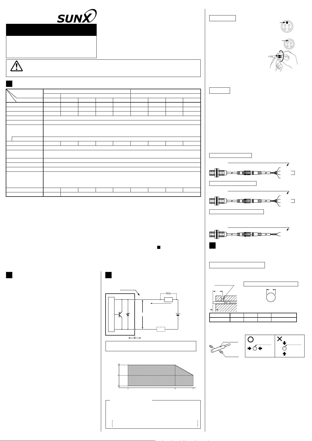
٨ I/O circuit diagram
2
, or more, cable.
Color code
(Brown) Output
Tr
Sensor circuit
Internal circuit Users' circuit
3V in ON state
Z
D
(Blue) 0V
Symbols...ZDTr: Surge absorption zener diode
: PNP output transistor
Note:
The maximum load current varies depending on the
ambient temperature.
70
35
(mA)
3
Max. load current
(1)
(2)
(3)
-25 55 70
Ambient temperature ()
Conditions for the load
The load should not be actuated by the leakage current
(0.8mA) in the OFF state.
The load should be actuated by (supply voltage - 3V) in the ON state.
The current in the ON state should be between 3 to 70mA DC.
In case the current is less than 3mA, connect a bleeder resistance
in parallel to the load so that a current of 3mA, or more, flows.
Bleeder resistance
Load
3 to 70mA in ON state (Note)
0.8mA in OFF state
Load
GX-18MLU(B) GX-30MLU(B)GX-12MLU(B)
15mmr10% 22mmr10%
0 to 12mm
Iron sheet 5050t1mm Iron sheet 7070t1mmIron sheet 3030t1mmIron sheet 2020t1mmIron sheet 1212t1mm Iron sheet 1818t1mm Iron sheet 3030t1mm
95g approx.
350Hz 220Hz650Hz1.0kHz1.2kHz 500Hz 350Hz1.2kHz1.7kHz
+
12 to 24V DC
+10
%
-15
-
0 to 17.6mm
220g approx.
٨ Spatter-resistant type and pigtailed type
Connection
ԘԙAlign the guide of the sen-
[Sensor side connector]
Convex
sor side connector with
the groove of the cable
side connector and push
[Cable side connector]
Concave
to mate the connectors.
Holding the fixing ring of
the sensor side connector, turn the fixing ring of
the cable side connector
clockwise till it stops.
Note: Tighten the fixing ring completely to make the
connection fully waterproof.
Removal
Ԙ
Turn the fixing ring counterclockwise and, holding
the fixing ring, pull to separate the connectors.
Notes: 1)
Use the mating cables as shown below.
CN-24-C2 (Oil, heat and cold resistant cable,
4-core, 2m, Do not use it near a welding place.)
CN-24-C5 (Oil, heat and cold resistant cable,
4-core, 5m, Do not use it near a welding place.)
CN-22G-C2 (Spatter-resistant cable, 2-core, 2m)
CN-22G-C5 (Spatter-resistant cable, 2-core, 5m)
When the 4-core mating cable is used with the
2)
pigtailed type sensor, the wire color code differs
from the color code of the cable type sensor.
GX-غU-J (Normally Open)
Mating cable color code / Connector pin No.
(Brown/1) Output
Not con-
(White)
nected
(Blue)
(Black/4) 0V
GX-غUB-J (Normally Closed)
Mating cable color code / Connector pin No.
(Brown/1) Output
Not con-
(Black)
nected
(Blue)
(White/2) 0V
GX-FغU-J (Spatter-resistant type)
The spatter-resistant mating cable has the same color code as the
cable of the spatter-resistant type sensor.
4
Mating cable color code / Connector pin No.
MOUNTING
(Brown/1) Output
(Blue/4) 0V
٨ The tightening torque should be under the value
given below.
Mounting with a set screw
٨ Tighten with the cup-point of a set screw (M4).
<Non-threaded type>
Set screw
(M4)
A
B
Do not fix on the operation indicator or opposite
٨
Mounting hole process dimension
C (mm)Model No. A (mm)
B (mm)
5 to 30
Ǿ5.5
C
Tightening torque
㧗0.2
0.78N㨯m3GX-5SUغ
0
to it.
Operation
indicator
Set screw
Operation
indicator
Operation
indicator
Page 2
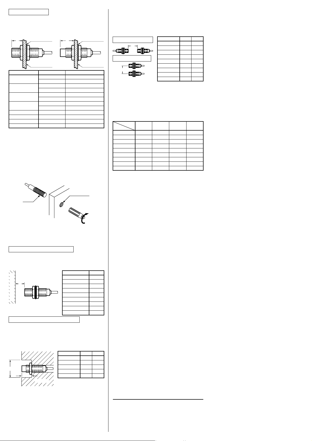
Mounting with nut
٨
Mount such that the nuts do not protrude from
the threaded portion.
<Shielded threaded type>
Attached toothed lock washer
D
Mounting plate
Model No.
GX-8MUغ
GX-غ12MUغ
GX-غ18MUغ
GX-غ30MUغ
GX-8MLUغ
GX-12MLUغ
GX-18MLUغ
GX-30MLUغ
٨
Caution with GX-8MUغ, GX-8MLUغ, GX-غ12MUغ
Dimension D (mm)
<Non-shielded threaded type>
Attached tooth-
D
3 to 10.3
10.3 or more
3.5 to 13.5
13.5 or more
4 to 18
18 or more
5VQ21
21 or more
12 or more
15 or more
25 or more
30 or more
ed lock washer
Mounting plate
Tightening torque
5.9N㨯m
11.8N㨯m
10N㨯m
20N㨯m
45N㨯m
80N㨯m
80N㨯m
180N㨯m
11.8N㨯m
20N㨯m
80N㨯m
180N㨯m
and GX-12MLUغ
The root truncation of the threaeds is shallow
owing to strengthening of the sensors against
tightening.
When tapping holes on equipment to fix the
sensors, the prepared hoels must be Ǿ7.2mm
or more with GX-8MUغ, and GX-8MLUغ,
Ǿ11.2mm or more with GX-غ12MUغ, and
GX-12MLUغ.
٨Mutual interference
When two or more sensors are installed in
parallel or face to face, keep the minimum
separation distance specified below to avoid
mutual interference.
Face to face mounting
H
Parallel mounting
J
Model No.
GX-5SUغ
GX-8MUغ
GX-غ12MUغ
GX-غ18MUغ
GX-غ30MUغ
GX-8MLUغ
GX-12MLUغ
GX-18MLUغ
H (mm)
115
145
250
٨Sensing range
The sensing range is specified for the standard sensing object. With a non-ferrous metal,
the sensing range is obtained by multiplying
with the correction coefficient specified below.
Correction coefficient
Metal
Model No.
GX-5SUغ
GX-8MUغ
GX-غ12MUغ
GX-غ18MUغ
GX-غ30MUغ
GX-8MLUغ
GX-12MLUغ
GX-18MLUغ
GX-30MLUغ
Note: The sensing range also changes if the sensing
object is plated.
Iron
1
1
1
1
1
1
1
1
1
Stainless steel
(SUS304)
0.63 approx.
0.59 approx.
0.75 approx.
0.75 approx.
0.69 approx.
0.64 approx.
0.67 approx.
0.68 approx.
0.67 approx.
Brass
0.32 approx.
0.32 approx.
0.51 approx.
0.50 approx.
0.44 approx.
0.38 approx.
0.44 approx.
0.45 approx.
0.44 approx.
19
20
35
70
60
Aluminum
0.30 approx.
0.29 approx.
0.49 approx.
0.48 approx.
0.42 approx.
0.38 approx.
0.43 approx.
0.43 approx.
0.43 approx.
J (mm)
14
15
20
45
70
45
95
165
250350GX-30MLUغ
Tapping holes
Sensor
٨Distance from surrounding metal
As metal around the sensor may affect the
sensing performance, pay attention to the following points.
Influence of surrounding metal
The surrounding metal will affect the sensing
performance. Keep the minimum distance
specified in the table below.
Model No. E (mm)
E
Background metal
GX-5SUغ
GX-8MUغ
GX-غ12MUغ
GX-غ18MUغ
GX-غ30MUغ
GX-8MLUغ
GX-12MLUغ
GX-18MLUغ
GX-30MLUغ
4.5
4.5
8
20
40
8
22
45
75
Embedding of the sensor in metal
Sensing range may decrease if the sensor is
completely embedded in metal. Especially for
the non-threaded type and the non-shielded
type, keep the minimum distance specified in
the table below.
Model No.
GX-5SUغ
GX-8MLUغ
F
G
Metal
GX-12MLUغ
GX-18MLUغ
GX-30MLUغ
F (mm)
Ǿ12
Ǿ24
Ǿ50
Ǿ75
Ǿ105
G (mm)
3
12
15
25
30
Note: With the non-shielded type, the sensing range may
vary depending on the position of the nuts.
SUNX Limited
http://www.sunx.co.jp/
Head Office
2431-1 Ushiyama-cho, Kasugai-shi, Aichi, 486-0901,
Japan
Phone: +81-(0)568-33-7211 FAX: +81-(0)568-33-2631
Overseas Sales Dept.
Phone: +81-(0)568-33-7861 FAX: +81-(0)568-33-8591
PRINTED IN JAPAN
 Loading...