

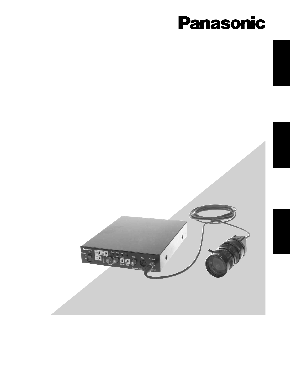
Panasonic GP-US522HAE, GP-US532HAE, GP-US522CUAE Operation Manual
Before attempting to connect or operate this product,
please read these instructions carefully and save this manual for future use.
Operating Instructions
3 CCD Colour Camera Head
Model No. GP-US522HAE
Model No. GP-US532HAE
3 CCD Colour Camera CCU
Model No. GP-US522CUAE
Lens : Purchased locally
Cable: Option
DEUTSCH
FRANÇAIS
ENGLISH
ENGLISH VERSION
The lightning flash with arrowhead symbol, within an equilateral triangle, is
interned to alert the user to the presence
of uninsulated "dangerous voltage" within
the product's enclosure that may be of
sufficient magnitude to constitute a risk of
electric shock to persons.
The exclamation point within an equilateral triangle is intended to alert the user
to the presence of important operating
and maintenance (servicing) instructions
in the literature accompanying the appliance.
The serial number of this product may be found on the
bottom of the unit.
You should note the serial number of this unit in the
space provided and retain this book as a permanent
record of your purchase to aid identification in the event
of theft.
Model No.
Serial No.
CAUTION: TO REDUCE THE RISK OF ELECTRIC SHOCK,
DO NOT REMOVE COVER (OR BACK).
NO USER-SERVICEABLE PARTS INSIDE.
REFER SERVICING TO QUALIFIED SERVICE PERSONNEL.
CAUTION
RISK OF ELECTRIC SHOCK
DO NOT OPEN
WARNING:
To reduce the risk of fire or electric shock, do not expose this appliance to rain or moisture.
Caution:
Before attempting to connect or operate this product,
please read the label on the bottom.
We declare under our sole responsibility that the product to which
this declaration relates is in conformity with the standards or other
normative documents following the provisions of Directive
EEC/89/336.
Dichiariamo sotto nostra esclusiva responsabilità che il prodotto a
cui si riferisce la presente dichiarazione è conforme agli standard o
altri documenti normativi ottemperanti alle disposizioni della direttiva
CEE/89/336.
Wij verklaren als enige aansprakelijke, dat het product waarop deze
verklaring betrekking heeft, voldoet aan de normen of andere normatieve documenten, overeenkomstig de bepalingen van Richtlijn
89/336/EEC.
Vi erklærer os eneansvarlige for, at dette produkt, som denne
deklaration omhandler, er i overensstemmelse med standarder eller
andre normative dokumenter i følge bestemmelserne i direktiv
89/336/EEC.
Vi deklarerar härmed värt fulla ansvar för att den produkt till vilken
denna deklaration hänvisar är i överensstämmelse med standarddokument, eller andra normativa dokument som framställs i EECdirektiv nr. 89/336.
Ilmoitamme yksinomaisella vastuullamme, että tuote, jota tämä
ilmoitus koskee, noudattaa seuraavia standardeja tai muita ohjeellisia asiakirjoja, jotka noudattavat direktiivin 89/336/EEC säädöksiä.
Vi erklærer oss alene ansvarlige for at produktet som denne
erklæringen gjelder for, er i overensstemmelse med følgende
normer eller andre normgivende dokumenter som følger bestemmelsene i direktiv 89/336/EEC.

3
CONTENTS
PREFACE ................................................................................................................................................................................... 4
FEATURES ................................................................................................................................................................................. 4
PRECAUTIONS .......................................................................................................................................................................... 5
MAJOR OPERATING CONTROLS AND THEIR FUNCTIONS .................................................................................................... 6
Camera Head ........................................................................................................................................................................... 6
Camera Control Unit ................................................................................................................................................................ 6
CONNECTIONS ......................................................................................................................................................................... 10
SETUP ........................................................................................................................................................................................ 12
1. CAMERA SETUP MENU ....................................................................................................................................................... 12
2. SETUP OPERATION ............................................................................................................................................................. 12
SETTING PROCEDURES ........................................................................................................................................................... 14
PREVENTION OF BLOOMING AND SMEAR ............................................................................................................................. 23
SPECIFICATIONS ..................................................................................................................................................................... 24
OPTIONAL ACCESSORIES ........................................................................................................................................................ 25
ENGLISH

4
Panasonic's GP-US522/532 Industrial Digital Signal
Processing Colour 3-CCD Camera overcomes space limitations that have complicated many video applications.
The GP-US522/532 incorporates three 440 000-pixel 752
(H) x 582 (V) Interline Transfer CCDs to give you a remarkable 800 lines (750 lines for GP-US532) of horizontal reso-
lution and a S/N ratio of 60 dB. This means a colour picture with high visual information content for excellent image
detail.
Because it features digital signal processing, the GPUS522/532 provides an exceptionally stable picture.
PREF ACE
FEATURES
1. High-performance micro prism optical system with
three IT CCDs
2. 800 lines of horizontal resolution for GP-US522 and 750
lines for GP-US532
3. Signal to noise ratio of 60 dB
4. Minimum scene illumination with + 18 dB gain of 5 lux
at F2.8 for GP-US522 and 9 lux at F2.2 for GP-US532
5. Auto Tracing White Balance (ATW), Auto White Balance
Control (AWC) or Manual White Balance Control are
selectable
6. Automatic Setting of Black Balance (ABC) or Manual
Setting
7. Gen-Lock capability
8. EBU colour bar generator
9. Automatic Gain Control (AGC) and Electronic Light
Control(ELC) are available
10. Automatic (AUTO), Step (STEP) and Manual (MANU)
setting of electronic shutter modes are selectable
11. 12V DC operation
12. RGB and S-Video Outputs
13. Character Generator Input
14. 2 SCENE files are selectable

5
PRECAUTIONS
1. Do not attempt to disassemble the camera or
camera control unit.
To prevent electric shock, do not remove screws or
covers.
There are no user-serviceable parts inside.
Ask a qualified service person for servicing.
2. Handle the camera and the camera control unit with
care.
Do not abuse the camera and the camera control unit.
Avoid striking, shaking, etc. The camera could be damaged by improper handling or storage.
3. Do not expose the camera or camera control unit to
rain or moisture, or try to operate it in wet areas.
Turn the power off immediately and ask a qualified service person for servicing. Moisture can damage the
camera and the camera control unit, and also create
the danger of electric shock.
4. Do not drop anything inside the camera or camera
control unit.
Dropping a metal part for example inside the camera
and camera control unit could permanently damage
the unit.
5. Do not crush or pinch the camera cable.
Avoid tight bends in the camera cable.
6. Never face the camera toward the sun.
Do not aim the camera at bright objects. Whether the
camera is in use or not, never aim it at the sun or other
extremely bright objects. Otherwise, blooming or smear
may be caused.
7. Do not use strong or abrasive detergents when
cleaning the camera or the camera control unit
body.
Use a dry cloth to clean the camera or the camera control unit when dirty.
In case the dirt is hard to remove, use a mild detergent
and wipe gently.
8. Clean the faceplate with care.
Do not clean the faceplate with strong or abrasive
detergents. Use lens tissue or a cotton tipped applicator and ethanol.
9. Put the lens cap on the camera after using the
camera.
After using the camera, turn the power of the camera
control unit off, and put the lens cap on the camera
head.
10. Do not connect units other than the camera head to
the GP-US522CU camera control unit.
Other connections may result in improper operation.
11. Do not operate the camera and the camera control
unit beyond the specified temperature, humidity, or
power source ratings.
Use the camera and the camera control unit under conditions where temperature is between 0°C - +45°C
(32°F - 113°F), and humidity is below 90 %. The input
power resource is 12 V DC.
12. Ask a qualified service person for installation.
All necessary procedures with regard to installation of
this product should be made by a qualified service person or system installer.
1. Connecting or disconnecting the camera cable
to/from the camera control unit or camera head
must be done after turning off the power of the
camera control unit.
2. Use the GP-CA522/4 (4 m/13 ft) camera cable
only for connection between the camera head
and camera control unit. Do not extend the
cable.
Cautions:
6
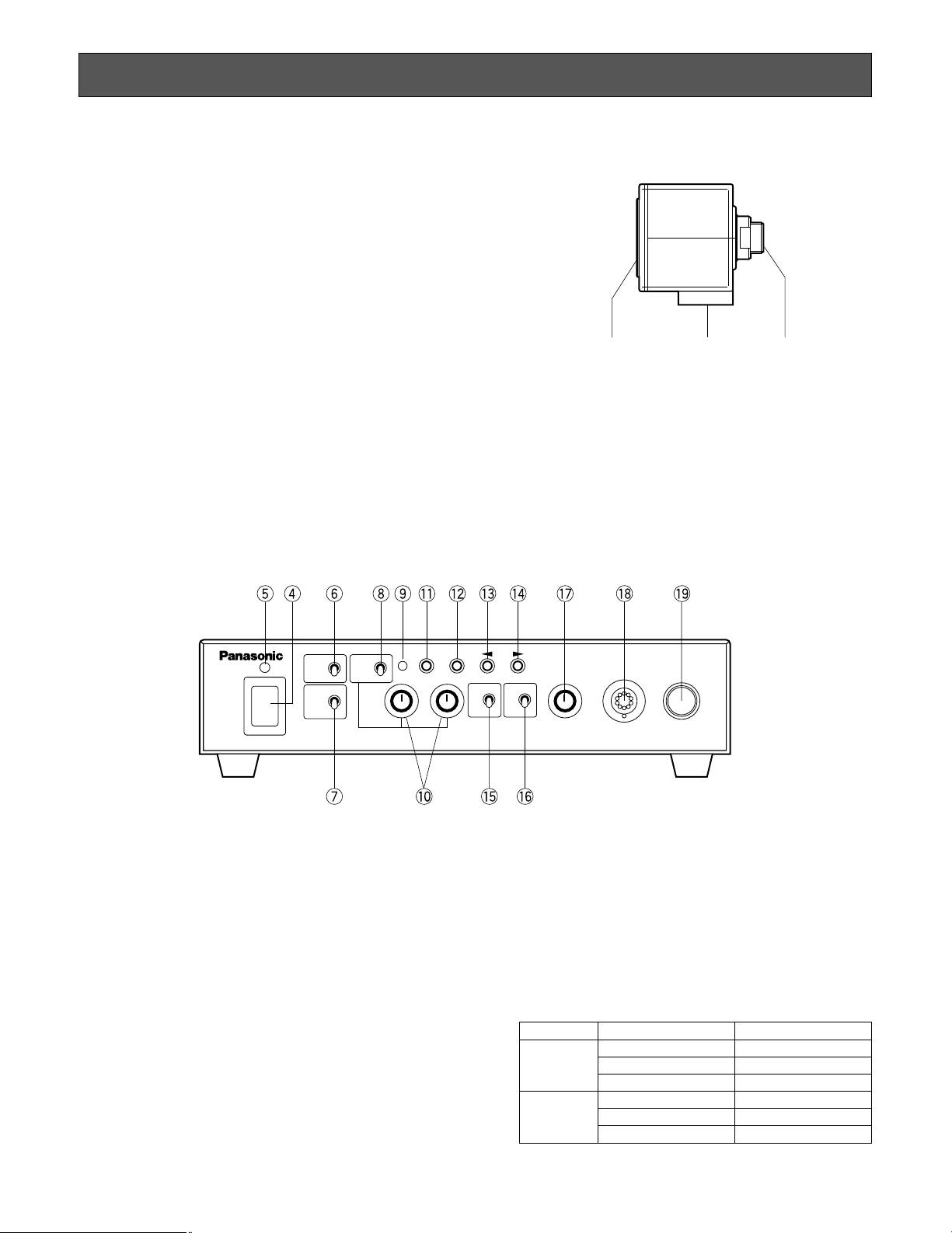
MAJOR OPERATING CONTROLS AND THEIR FUNCTIONS
Camera Head
1. Lens Mount
This is used to attach the special C-mount lens for GPUS522 and the C-mount lens for GP-US532.
2. Camera Cable Connector
This 24-pin connector is used to connect the optional
camera cable GP-CA522/4 to the camera control unit.
3. Camera Mounting Screw Hole
This hole (1/4" - 20) is used to mount the camera onto
a mounting bracket.
4. Power ON/OFF Switch (DC POWER ON/OFF)
This switch turns the power of this unit and the power
supply for the camera head on or off.
5. Power Indicator (POWER)
This indicator lights up red when the power switch is
turned on.
6. Automatic/Manual Gain Selector Switch
(GAIN HIGH/LOW/OFF)
This selector is used to select the gain of the video
amplifier as follows.
The mode can be selected in the SETUP menu.
Refer to page 17.
Camera Control Unit
[Front Panel]
MODE SW POSITION GAIN
HIGH Maximum +18 dB
AUTO LOW Maximum + 9 dB
OFF 0 dB
HIGH +18 dB (Fixed)
MANU LOW + 9 dB (Fixed)
OFF 0 dB
q e w
CAM
HIGH
ATW
MANU
LOW
OFF
BAR
R B
1
2
SCENE
ON
OFF
ELC
LEVEL TITLE CAMERA
PAGE ITEM
(AWC) (ABC)
GAIN
DC POWER
ON
OFF
AWC
Camera Control Unit
GP-
US522
GAIN

7
7. Camera/Colour Bar Selector (CAM/BAR)
This selector is used to select either the video signal or
the EBU colour bar signal which is output from the
video output connector (VIDEO), YC (S-VIDEO) output
connector or RGB (D-SUB, 9-pin) output connector.
CAM :The video signal from the camera is output.
BAR : The EBU colour bar signal is output.
Set this switch to BAR when making video monitor
adjustments and recording the colour bar signal.
8. White Balance Selector (ATW/AWC/MANU)
This selector is used to select one of the following
white balance modes.
ATW : In this mode, the colour temperature is moni-
tored continuously and thereby white balance is
set automatically.
AWC : In this mode, accurate white balance is
obtained.
The white balance settings are as follows:
1. Aim the camera at a white chart.
2. Press the ITEM (AWC) button on the front
panel to set the white balance.
3. When the auto white balance is completed,
the auto warning indicator first blinks and then
goes off.
If the auto warning indicator remains lit, repeat the
above procedure for setting the auto white balance.
MANU : The white balance can be adjusted manually
with the red gain (R GAIN) and blue gain controls
(B GAIN).
9. Auto Warning Indicator
This indicator blinks while the white balance or black
balance is being automatically set. This indicator lights
continuously when the white balance or black balance
is set improperly. In this case, follow the auto white
balance or black balance setting procedure.
10. Red and Blue Gain Controls (R GAIN/B GAIN)
These controls are used to manually adjust the white
balance.
These controls only work when the white balance
selection switch (ATW/AWC/MANU) is set to MANU.
Turn the controls clockwise to increase the red and
blue signal levels, and counterclockwise to decrease.
11. Page Button (PAGE)
This button is used to display the SETUP menu by
pressing it for 2 seconds or more, and to change the
parameters in the SETUP menu.
12. Item Button (ITEM/AWC)
While the SETUP menu is displayed, this button is
used to move the cursor downward.
Normally, when the white balance selection switch
(ATW/AWC/MANU) is set to AWC, this button is used
to set the automatic white balance control (AWC).
13. Left Button (A/ABC)
While the SETUP menu is displayed, this button is
used to move the cursor to the left.
Normally, this button is used to set the automatic black
balance control (ABC).
14. Right Button (B)
This button is used to move the cursor to the right in
the SETUP menu.
15. Scene File Selector (SCENE)
This selector is used to select the scene files.
16. Electronic Light Control ON/OFF Selector
(ELC ON/OFF)
This selector is used to select the electronic light control mode as follows:
ON : Enables Electronic Light Control (ELC) mode and
disables Electronic Shutter Speed (SHUTTER)
mode.
OFF : Enables Electronic Shutter Speed (SHUTTER)
mode and disables Electronic Light Control (ELC)
mode.
Note :
Confirm the setting of the ELC and SHUTTER
parameters on the SETUP menu.
17. Electronic Shutter Speed Control (LEVEL)
This control is used to set the target value of the
Electronic Shutter Speed between 1/50 and 1/10
000 seconds together with the ELC ON/OFF switch.
18. Title Input Connector (TITLE)
This connector is used to connect the optional
Character Generator WJ-KB30 or WJ-KB50.
Note :
The Black and White characters of the generator
are mixed with the video signal and are obtained
at VIDEO OUT, S-VIDEO (Y/C) OUT and
RGB/SYNC OUT connectors.
Colourization of characters is not available.
8
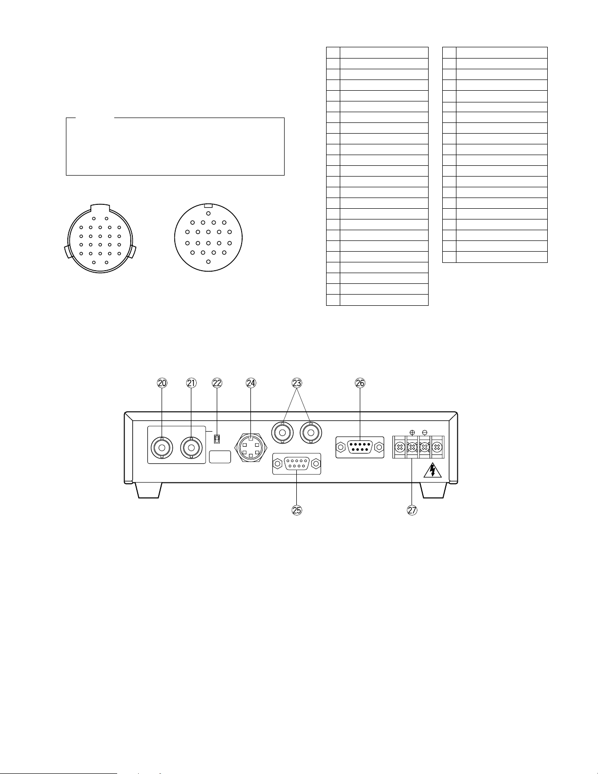
Camera Head Side Camera Control Unit Side
1 +15V Input
2 Ground (GND)
3 Chip Select Input
4 +25 Input
5 –9V Input
6 B Signal Output
7 RGB Ground (GND)
8 Serial Data Input
9 Serial Clock Input
10 CCD Select Output
11 G Signal Output
12 R Signal Output
13 VD Input
14 CPOB Output
15 HD Input
16 +9V Input
17 +5V Input
18 Not used
19 Not used
20 Not used
21 Not used
22 Not used
23 28 MHz Input
24 Not used
1 Ground (GND)
2 Not used
3 Not used
4 +9V Output
5 −9V Output
6 28MHz Output
7 CPOB Input
8 RGB Ground (GND)
9 +5V Output
10 B Signal Input
11 Serial Clock Output
12 VD Output
13 Chip Select Output
14 +25 Output
15 R Signal Input
16 Serial Data Output
17 HD Output
18 G Signal Input
19 +15V Output
20 CCD Select Input
19. Camera Cable Connector (CAMERA)
This 20-pin connector is used for connection with the
camera head via the optional camera cable GPCA522/4.
Fasten the camera cable to this connector firmly.
If not, noise may appear.
20. Gen-lock Signal Input Connector (VBS/HD)
The colour video signal of the camera is automatically
synchronized with the gen-lock signal (Composite
Signal, Black Burst Signal or Video Sync) when either
signal is supplied to this connector.
The gen-lock signal is used for system reference.
Caution :
If the gen-lock signal is jittery (as in the case of a
VTR playback picture), the camera cannot be synchronized properly.
(External HD and VD Mode)
The horizontal and vertical pulse of the colour
video signal is synchronized with the external HD
fed to this connector and external VD fed to the VD
input connector.
21. Gen-Lock Signal Input Connector (VD)
Supply the external vertical drive (VD) pulse to this
connector.
22. Gen-Lock Video 75 Ω Termination ON/OFF Switch
(75 Ω ON/OFF)
When looping through the gen-lock video signal with a
BNC “T” adapter, set this switch to OFF. When not
looping through, set this switch to ON.
23. Video Output Connector (VIDEO 1,2)
A 1.0V[p-p]/75 Ω composite video signal is provided at
this connector.
[Rear Panel]
For Camera
VBS/HD VD
OFF
ON
75Ω
S-VIDEO
OUT
1 2VIDEO
RS-232C
RGB/SYNC
DC 12V IN
Connecting or disconnecting the camera cable
to/from the camera control unit or camera head
must be done after turning off the Power of the
camera control unit.
Caution:
1
2
5
6
10
1511
19
20
16
For CCU
21221520
24 23
2
1
1617
101112
567
1819
1314
89
34
 Loading...