

Page 1
Before attempting to connect or operate this product,
please read these instructions carefully and save this manual for future use.
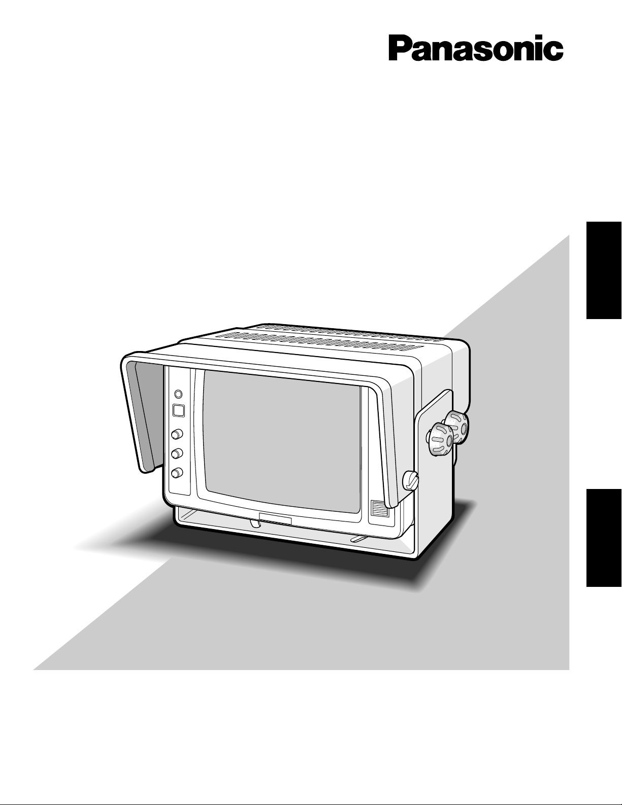
Model No. GP-RV700
Car-Use B/W Monitor
Operating Instructions
ENGLISH
FRANÇAIS
Page 2
2
The serial number of this product may be found on the bottom of the unit.
You should note the serial number of this unit in the space
provided and retain this book as a permanent record of your
purchase to aid identification in the event of theft.
Model No. GP-RV700
Serial No.
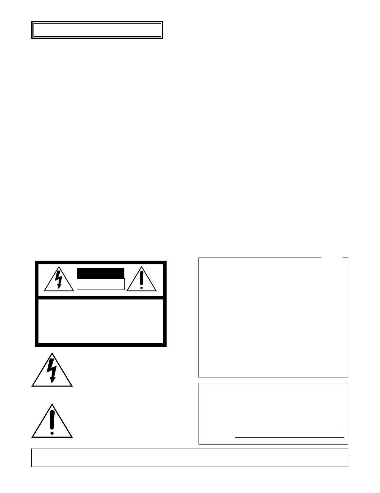
WARNING:
To reduce the risk of fire or electric shock, do not expose this appliance to rain or moisture.
The lightning flash with arrowhead symbol, within an equilateral triangle, is
intended to alert the user to the presence of uninsulated "dangerous voltage"
within the product's enclosure that may
be of sufficient magnitude to constitute a
risk of electric shock to persons.
The exclamation point within an equilateral triangle is intended to alert the user
to the presence of important operating
and maintenance (servicing) instructions
in the literature accompanying the appliance.
CAUTION: TO REDUCE THE RISK OF ELECTRIC SHOCK,
DO NOT REMOVE COVER (OR BACK).
NO USER-SERVICEABLE PARTS INSIDE.
REFER SERVICING TO QUALIFIED SERVICE PERSONNEL.
CAUTION
RISK OF ELECTRIC SHOCK
DO NOT OPEN
SA 1965
SA 1966
NOTE: This equipment has been tested and found to comply
with the limits for a Class A digital device, pursuant to Part
15 of the FCC Rules. These limits are designed to provide
reasonable protection against harmful interference when the
equipment is operated in a commercial environment. This
equipment generates, uses, and can radiate radio frequency
energy and, if not installed and used in accordance with the
instruction manual, may cause harmful interference to radio
communications.
Operation of this equipment in a residential area is likely to
cause harmful interference in which case the user will be
required to correct the interference at his own expense.
FCC Caution: To assure continued compliance, (example use only shielded interface cables when connecting to computer or peripheral devices). Any changes or modifications
not expressly approved by the party responsible for compliance could void the user’s authority to operate this equipment.
For U.S.A
Caution:
Before attempting to connect or operate this product,
please read the label on the bottom.
ENGLISH VERSION
Page 3

3
CONTENTS
PREFACE ........................................................................................................................................................................................ 4
FEATURES ...................................................................................................................................................................................... 4
PRECAUTIONS ............................................................................................................................................................................... 4
MAJOR OPERATING CONTROLS AND THEIR FUNCTIONS ........................................................................................................ 5
INSTALLATIONS ............................................................................................................................................................................ 6
SYSTEM CONNECTION ................................................................................................................................................................. 7
ADJUSTMENT ................................................................................................................................................................................ 7
OPERATING PROCEDURES .......................................................................................................................................................... 8
VIEWED RANGE ............................................................................................................................................................................. 8
APPEARANCE ................................................................................................................................................................................ 9
SPECIFICATIONS ......................................................................................................................................................................... 10
STANDARD ACCESSORY ............................................................................................................................................................ 10
OPTIONAL ACCESSORY ............................................................................................................................................................. 10
ENGLISH
Page 4

4
The GP-RV700 rearview monitor is designed exclusively for
use in large tracks, buses and other commercial vehicles.
When combined with Panasonic’s Rearview Camera, dangerous blind spots can be reduced significantly.
PREF ACE
• Refer all work related to the installation of this
product to qualified service personnel or system
installers.
• Do not block the ventilation opening or slots in the
cover.
To prevent the appliance from overheating, place it
paying attention to the ventilation space.
• Do not drop metallic parts through slots.
This could permanently damage the appliance. Turn
the power off immediately and contact qualified service
personnel for service.
• Do not attempt to disassemble the appliance.
To prevent electric shock, do not remove screws or
covers.
There are no user-serviceable parts inside. Contact
qualified service personnel for maintenance.
• Handle the appliance with care.
Do not strike or shake, as this may damage the appliance.
• Do not expose the appliance to water or moisture,
nor try to operate it in wet areas.
Do take immediate action if the appliance becomes
wet. Set the ignition to the LOCK position or pull the
ignition key out and refer servicing to qualified service
personnel. Moisture may damage the appliance and
also cause electric shock.
• Do not use strong or abrasive detergents when
cleaning the appliance body.
Use a dry cloth to clean the appliance when it is dirty.
When the dirt is hard to remove, use a mild detergent
and wipe gently.
• Do not operate the appliance beyond its specified
temperature, humidity or power source ratings.
Use the appliance at temperatures within –10˚C - +55˚C
(14˚F - 131˚F) and at a humidity below 90 %.
The input power source for this appliance is 12 V DC.
Note: The images on the monitor are displayed reversibly
on right and left, just like that of the rearview mirror.
PRECAUTIONS
FEATURES
• Easy to see screen: 176 mm (7-inch) flat square and
non-glare screen
• Automatic Brightness Control (ABC) to compensate for
ambient light.
• Remote STANDBY/ON control by reverse gear position
signal.
• Manual STANDBY/ON mode selection.
• Compact designed black and white monitor enables to
fit almost anywhere.
Page 5

5
MAJOR OPERATING CONTROLS AND THEIR FUNCTIONS
CONTRAST
STD BY/ON
BRIGHT
AUDIO
ABC
MIN MAX
THIS DEVICE
SER.
NO.
CAUTION
. . .
THIS CLASS
. . .
FOCUS
REMOTE
CAMERA
q
w
e
r
t
!1
y
u
!2
q Mode Selector (STD BY/ON)
Toggles the operation mode standby and on.
STD BY: No image is on the monitor but the picture
tube is preheated on standby.
The indicator is lit green while this mode is selected.
ON: Displays camera images on the monitor.
The indicator is lit amber while this mode is selected.
w Contrast Control (CONTRAST)
Adjusts the picture contrast. Turn this control clockwise
to increase the picture contrast, and turning the control
counterclockwise has the reverse effect.
e Brightness Control (BRIGHT)
Adjusts the picture brightness. Turn this control clockwise to increase the picture brightness, and turning the
control counterclockwise has the reverse effect.
r Audio Control (AUDIO)
Adjusts the volume. Turn this control clockwise to
increase the volume, and turning the control counterclockwise has the reverse effect.
t Auto Brightness Control Sensor (ABC)
This sensor detects illumination intensity.
y Monitor Fixing Screws
These four screws are used to secure the monitor. The
monitor can be tilted approximate 30 degrees by loosing these screws.
u Mounting Bracket
Installs the monitor to a vehicle.
!1 Focus Control (FOCUS)
This control is preset at the factory.
!2 Remote/Camera Connector (REMOTE/CAMERA)
This 9-pin connector is used to connect the remote
cable assembly supplied as an accessory for supplying
the power and connecting the camera.
● Front View ● Rear View
Page 6

6
2. Place the mounting bracket on the position to be
installed in the vehicle, and secure it with the four bolts
(procured locally ø6 mm).
1. Remove the Mounting Bracket from the monitor by
removing the four monitor fixing screws.
INSTALLATIONS
3. Place the monitor onto the bracket and tighten with the
four monitor fixing screws.
4. Install the GP-Q48 monitor hood (option) by tightening
the two screws supplied, if required.
Connect
Remote
Cable
To Rearview Monitor
q +12 V DC (red)
w Remote In (blue)
e Not Used
r Ground (green)
t Audio In (white)
y Video In (yellow)
u Ground (green)
i Camera Ground (black)
o +9 V DC (red)
To Rearview Camera
q Audio In (white)
w Video In (yellow)
e Camera Ground (black)
r +9 V DC (red)
1 2 3
4 5 6
7 8 9
wq
re
5. Connect the remote cable to the REMOTE/CAMERA
connector on the rear of the monitor.
The remote cable is designated as shown in the figure
below.
Remove screws
Page 7

7
BATTERY
Fuse box
Reverse
Switch
(Shift Gear)
+12 V (Red)
3 A
To Reverse Light
Chassis (GROUND) (Green)
CAMERA
Camera Cable
9-pin
CONNECTOR
MONITOR
Remote (Blue)
ADJUSTMENT
The following adjustment should be made by qualified
service personnel or system installers.
The monitor comes with two templates for use with the
height between 2 meters (6.6 feet) and 2.8 meters (9.2 feet)
or higher camera position.
Choose the required template, peel off the tape, and fix the
template onto the monitor screen.
(ft) (m)
30
15
10
3
10
5
3
1
00
Approx. 16 ft (5 m) Line
Approx. 3.3 ft
(1 m) Line
<Lower Height>
(ft) (m)
30
15
10
3
10
5
3
0
<Higher Height>
1. Select the ON mode by pressing the STD BY/ON button
on the monitor.
The rearview image is displayed on the monitor screen.
2. Adjust the camera tilt to become the image that the rear
bumper is displayed on the reference line on the monitor screen.
Reference
Line
CONTRAST
STD BY/ON
BRIGHT
AUDIO
ABC
MIN MAX
(ft) (m)
30
15
10
3
10
5
3
1
00
Monitor Screen
Rear
Bumper
SYSTEM CONNECTION
Page 8

8
OPERATING PROCEDURES
1. Turn the ignition switch to the ON position and confirm
that the STD BY/ON indicator on the monitor lights
green (standby mode).
CONTRAST
STD BY/ON
BRIGHT
AUDIO
ABC
MIN MAX
Lights to
Green
2. Whenever shifting the gear lever to the reverse position,
the indicator becomes to light amber (on mode) and the
rearview image will appear on the monitor screen in a
few seconds.
CONTRAST
STD BY/ON
BRIGHT
AUDIO
ABC
MIN MAX
R
Lights to
Amber
3. Whenever shifting the gear lever to other than reverse
position, the indicator becomes to light green and the
image will on the monitor disappear.
4. The rearview image can be displayed on the monitor by
pressing the STD BY/ON button even the gear lever is
not positioned in reverse.
Press the button to toggle rearview display on and off
on the monitor.
5. Turn the BRIGHT, CONTRAST and AUDIO controls to
adjust the volume and for clear images.
VIEWED RANGE
5 m (16.5 ft)5 m (16.5 ft)
5 m (16.5 ft)
10 m (33 ft)
15 m (50 ft)
20 m (66 ft)
78°
14.1 m (46 ft)
3 m (10 ft)
Page 9

9
APPEARANCE
Unit: mm (inches)
221 (8-11/16)
. . .
PRODUCT
. . .
Model No.
STD BY/ON
CONTRAST
BRIGHT
AUDIO
MIN MAX
208 (8-3/16)
58
20 (13/16)50 (2)
(2-5/16)
°
20
ABC
142 (5-9/16)
10°
164 (6-7/16)
Page 10

10
Power Required: 12 V DC (10 V - 16 V DC) 1.8 A
Power Consumption: 22 W (ON mode), 2 W (STD BY mode)
Screen Size: 191.6 mm (7-9/16”) diagonal tube size, 90˚ deflection.
176.3 mm (6-15/16’’) diagonal actual visual size.
Horizontal Resolution: 500 TV lines at center
Speaker Output: 0.5 W max.
Automatic Brightness Control: Yes
Vibration Resistance: 4.4 G (10 Hz - 100 Hz)
Ambient Operating Temperature: –10˚C - +55˚C (14°F - 131°F)
Ambient Operating Humidity: Less than 90 %
Dimensions: 221 (W) x 142 (H) x 208 (D) mm
(Excluding Hood and Mounting Bracket) 8-11/16” (W) x 5-9/16” (H) x 8-3/16” (D)
Weight: 4.3 kg (9.5 lbs.)
Weight and Dimensions indicated are approximate.
Specifications are subject to change without notice.
SPECIFICATIONS
Remote Cable Assembly ...................................................... 1 pc
Template ............................................................................... 2 pcs.
STANDARD ACCESSOR Y
Monitor Hood ........................................................................ GP-Q48
OPTIONAL ACCESSOR Y
Page 11

N0300-0 YWV8QA5369AN Printed in Japan
N 19 Imprimé au Japon
© Matsushita Communication Industrial Co., Ltd. 2000
Panasonic Canada Inc.
5770 Ambler Drive, Mississauga,
Ontario, L4W 2T3 Canada (905)624-5010
Panasonic Sales Company
Division of Matsushita Electric of Puerto Rico Inc.
Ave. 65 de Infanteria. Km. 9.5
San Gabriel Industrial Park, Carolina,
Puerto Rico 00985 (809)750-4300
Panasonic Security & Digital Imaging Company
A Division of Matsushita Electric Corporation of America
Industrial / Medical Group
Executive Office: One Panasonic Way 3E-7, Secaucus, New Jersey 07094
TEL: (201) 392-6674 / FAX: (201) 348-5346
Regional Office
Northeast: 43 Hartz Way, Secaucus, NJ 07094 (201) 348-7303
Southern: 1225 Northbrook Parkway, Suite 1-160, Suwanee, GA 30124 (770) 338-6838
Midwest: 1707 North Randall Road, Elgin, IL 60123 (847) 468-5200
Southwest:8105 Beitsline Road, Suite 100, Irving, TX 75063 (214) 915-1333
Western: 6550 Katella Ave., Cypress, CA 90630 (714) 373-7265
 Loading...