

Page 1

ModeRear Panel Switch
1. Newly developed 2/3” double speed progressive scan type CCD image sensor with 768
(H) x 494 (V) pixels.
2. External synchronization :
External HD/VD input enables system setup
with external video processors, etc.
4. Frame reset with Read out Inhibit (R/I)
control :
R/I control (this controls the timing of Readout
Inhibition from CCD) enables to capture the
same timing pictures from two or more cameras into one image memory.
FEATURES
The Panasonic GP-MF852PT Double Speed Machine Vision Camera has a 2/3” Interline Transfer CCD
image sensor which features 380 000 pixels, a horizontal resolution of 500 lines, and minimum smear.
5. Clean the CCD faceplate with care.
Do not clean the CCD with strong or abrasive
detergents. Use lens tissue or a cotton tipped
applicator and ethanol.
6. Never face the camera towards the sun.
Do not aim the camera at bright objects.
Whether the camera is in use or not, never
aim at the sun or other extremely bright
objects. Otherwise, blooming or smear may
be caused.
7. Do not drop anything inside the camera.
Dropping metal for example inside the camera could permanently damage the unit. If
anything is dropped inside the camera, turn
the power off immediately and ask a qualified
service person for servicing.
8. Do not operate the camera beyond the
specified temperature, humidity or power
source ratings.
Use the camera under conditions where temperature is between −10°C - +50°C (14°F 122°F), and humidity is below 90 %.
The input power source is DC 12 V, 465 mA.
PREF ACE
Before attempting to connect or operate this product,
please read these instructions completely.
CAUTION
RISK OF ELECTRIC SHOCK
DO NOT OPEN
CAUTION:
TO REDUCE THE RISK OF ELECTRIC
SHOCK, DO NOT REMOVE COVER (OR
BACK), NO USER SERVICEABLE PARTS
INSIDE.
REFER SERVICING TO QUALIFIED SERVICE
PERSONNEL.
The exclamation point within an
equilateral triangle is intended to
alert the user to the presence of
important operating and maintenance (servicing) instructions in the
literature accompanying the appliance.
The lightning flash with arrowhead
symbol, within an equilateral triangle, is interned to alert the user to
the presence of uninsulated "dangerous voltage" within the product's
enclosure that may be of sufficient
magnitude to constitute a risk of
electric shock to persons.
WARNING:
TO PREVENT FIRE OR ELECTRIC SHOCK HAZARD, DO NOT EXPOSE THIS APPLIANCE TO
RAIN OR MOISTURE.
The serial number of this product may be found on
the top of the unit.
You should note the serial number of this unit in the
space provided and retain this book as a permanent record of your purchase to aid identification in
the event of theft.
Model No.
Serial No.
SA 1966
SA 1965
VIDEO
1ON2 3 4 5 6 7 8
r
e
w
tyio!0!1u
q
MAJOR OPERATING CONTROLS AND THEIR FUNCTIONS
q 2/3” Manual Iris Lens (Sold Separately)
w Camera Connector (12-pin)
This is connected with the optional Camera
Cable GP-CA34 , GP-CA33, GP-CA59 or GPCA60.
N1098-0 YWV8QA5088AN Printed in Japan
N 30
Warning:
This equipment generates and uses radio frequency energy and if not installed and used properly,
i.e., in strict accordance with the instruction manual, may cause harmful interference to radio communications. It has been tested and found to comply with the limits for a Class A computing device
pursuant to Subpart J of Part 15 of FCC Rules,
which are designed to provide reasonable protection against such interference when operated in a
commercial environment.
For U.S.A
Machine Vision Camera
GP-MF852PT
Remove dust on the faceplate of filter glass
before mounting the lens on the camera.
Pin No. Description
1 Ground
2 +12V IN
3 Ground for Video Out
4 Video Out
5 Ground for HD
6 HD IN
7 VD/V reset
8 Ground
9 No connection
10 No connection
11 No connection
12 Ground for VD
CAUTION: CONNECT
THIS TO A DC 12 V
CLASS 2 POWER
SUPPLY ONLY.
3. Video Output Connector
This connector is used to connect with the
VIDEO IN connector of the monitor.
8. Rear Panel Switch No.4 (4/ON)
4ON
9. Rear Panel Switch No.5 (5/ON) 5ON
These switches (Rear Panel Switch No. 4, 5,
6, and 7) are used to set the shutter speed.
The shutter speed changes according to the
mode which is set by the Rear Panel Switch
No. 2, 3, and 8.
10. Rear Panel Switch No.6 (6/ON) 6ON
11. Rear Panel Switch No.7 (7/ON) 7ON
The shutter speed can be set as below:
No.4 No.5 No.6 No.7
OFF OFF OFF OFF
ON OFF OFF OFF
OFF ON OFF OFF
ON ON OFF OFF
OFF OFF ON OFF
ON OFF ON OFF
OFF ON ON OFF
ON ON ON OFF
OFF OFF OFF ON
ON OFF OFF ON
Mode 7 Mode 2-5
Normal
Not Specified
Not Specified
Not Specified
Not Specified
Not Specified
1/30 000
1/15 000
1/8 000
1/4 000
1/2 000
1/30 000
1/15 000
1/8 000
1/4 000
1/2 000
1/1 000
1/500
1/250
1/100
qo
w!0i
e!1 u!2
rty
Page 2
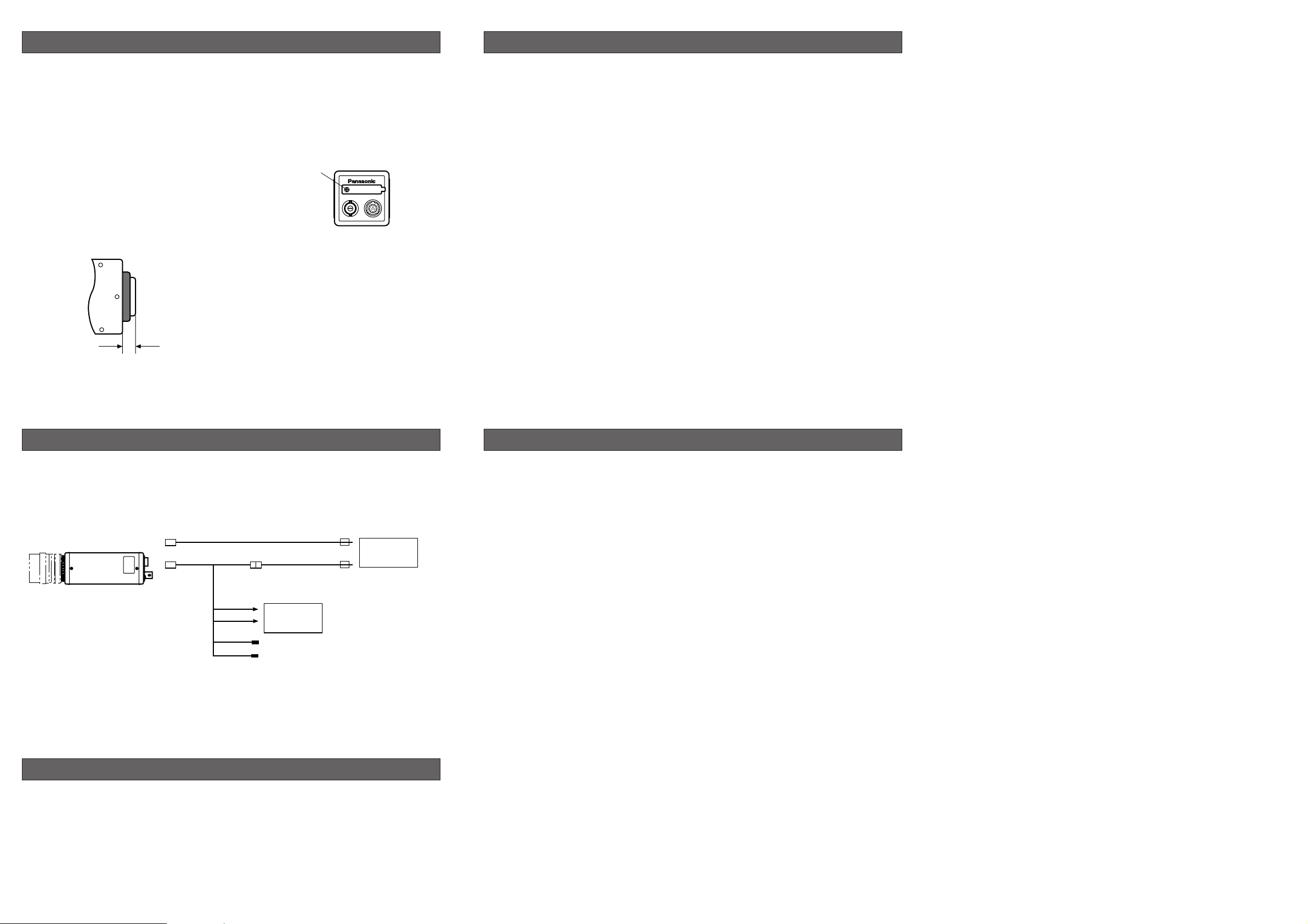
PREPARATIONS
SYSTEM CONNECTIONS
EXTERNAL SYNCHRONIZATION
1. Power Supply for Camera
Prepare a regulated DC power supply which
can supply DC 12 V ±10 % DC 465 mA or
more current and rated CLASS 2.
2. Lenses
Be sure to use the optional manual iris lens
having the following items.
Focus : Adjustable
Lens Weight : Less than 300 g (0.66 lbs.)
Note: If the lens is heavier than 300 g (0.66
lbs.), both the lens and the camera
should be secured by using the support-
er.
Mount : C-mount
The protrusion at the rear of the lens should
be as shown in the illustration.
Less than 7.5 mm (1/2”)
Pick-up Device : Inter Line Transfer type CCD with 768 (H) x 494 (V) pixels.
Image Size : 2/3” (7.95 (H) x 6.45 (V) mm)
Full non interlace (1/60 s)
Synchronization : Internal or External (Selectable Automatically)
Internal : Built-in sync generator
External : 4.0 V[p-p]/75 Ω Horizontal drive and Vertical drive pulses
External Reset : External signal (4.0 V[p-p]/75 Ω, negative) supplied to EXT VD IN
connector can be used as reset signal
Horizontal Resolution : 500 lines at center
Minimum Illumination : 5 lx (0.5 foot-candles), (F1.4, Gain (+6 dB) , γ OFF)
Gamma : 1.0
Gain Selection : 0/+6 dB
Electronic Shutter : 9-step (1/100 s to 1/30 000 s) at normal
5-step (1/2 000 s to 1/30 000 s) at Shutter Trigger
Lens Mount : C-Mount
Vibration Resistance : 7 G (10 Hz - 150 Hz) (2 hours each for three axes)
Shock Resistance : 80 G (IEC 68) *IEC=International Electronical Technical Commission
Power Source : DC + 12 V, 465 mA
Ambient Temperature : −10˚C - +50˚C (14˚F - 122˚F)
Dimensions : 45(W) x 45(H) x 120(D) mm [1-25/32”(W) x 1-25/32”(H) x 4-23/32”(D)]
Weight : 270 g (0.6 lbs.) (Camera Only)
Dimensions and weight indicated are approximate values.
Specifications are subject to change without notice.
SPECIFICATIONS
OPTIONAL ACCESSORIES
Camera Cable GP-CA34
GP-CA33
GP-CA59
GP-CA60
3. Switch Covers Removal
Caution: The following preparation should be
made by qualified service personnel or
system installers.
For setting the Rear Panel Switch No.1 to 8,
remove the switch cover fixing screw on the
rear panel as shown below.
VIDEO
Remove
this screw
Caution: Keep the power switches of all units to OFF before connections.
1. Connect the optional camera cable GP-CA34 between the connector of this camera and the 12 V DC
Class 2 power supply(not provided as an accessory).
2. Connect the video connector of the GP-CA34 to the Frame Grabber.
Camera
Video input of
Frame Grabber
GP-CA34
HD IN
VD/V reset
Caution: Use a 12 V DC Class 2
Power Supply only
12V DC
Power Supply
Full non interlace
The GP-MF852PT works in full non interlace mode
when external HD/VD signal is supplied to pin-6
and pin-7 of the camera connector (12-pin).
Notes:
• If the picture appears disturbed, be sure to
match the phases of falling edges of the
external HD/VD.
• Normal monitor cannot display the picture
from this camera. To display the picture, synchronize the camera and multiscan monitor
from external HD/VD.
 Loading...