

Page 1
Operating
instructions
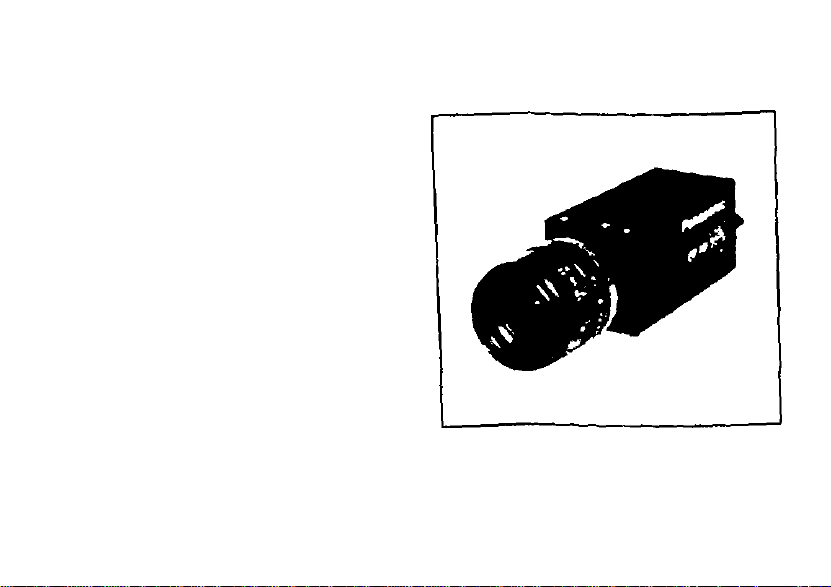
Machine Vision B/W CCD Camera
GP-MF130
Panasonic.
pl#et* nSlTi>CbC>^9 COnpIMMy
Of tfM product
Page 2
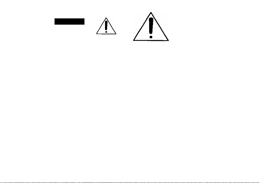
CAUTION
RISK OF ELECTRIC SHOCK
A
CAUTION:
TO REDUCE THE RISK OF ELECTRIC SHOCK,
DO NOT REMOVE COVER (OR BACK). NO
USER-SERVICEABLE PARTS INSIDE.
REFER SERVICING TO QUAUFIED SERVICE
PERSONNEL
A
SA 1965
□ ONOT OPEN
The lightning flash with arrow
head symbol, within an equilat
eral triangle, is intended to alert
the user to the presence of
uninsulated "dangerous volt
age" within the product's enclo
sure that may be of sufficient
magnitude to constitute a risk
of electric shock to persons.
The exclamation point within an
equilateral triangle is intended to
alert the user to the presence of
important operating and mainte
nance (servicing) instructions in the
SA 1966
Warning:
This equipment generates and uses radio fre
quency energy and if not installed and used
properly, i.e., in strict accordance with the
instruction manual, may cause harmful interfer
ence to radio communications. It has been test
ed and found to comply with the limits for a
Class A computing device pursuant to Subpart J
of Part 15 of FCC Rules, which are designed to
provide reasonable protection against such
interference when operated in a commercial
environment.
literature accompanying the appli
ance.
WARNING: TO PREVENT FIRE OR ELECTRIC SHOCK HAZARD, DO NOT EXPOSE THIS
APPLIANCE TO RAIN OR MOISTURE.
Page 3

CONTENTS
PREFACE ........................................................ 2
FEATURES ...................................................... 2
PRECAUTIONS ............................................... 3
MAJOR OPERATING CONTROLS AND
THEIR FUNCTIONS
PREPARATIONS
SYSTEM CONNECTIONS
EXTERNAL SYNCHRONIZATION
PREVENTION OF BLOOMING AND SMEAR .. 10
SPECIFICATIONS
OPTIONAL ACCESSORIES
Remove dust on the faceplate of filter glass
before mounting the lens on the camera.
........................................
............................................
..............................
..................
..........................................
............................
5
8
9
10
11
12
The serial number of this product may be found on
the top of the unit.
You should note the serial number of this unit in the
space provided and retain this book as a permanent
record of your purchase to aid identification in the
event of theft.
Model No.
___________________________
Serial No.
- 1 -
Page 4

PREFACE FEATURES
The Panasonic GP-MF130 Machine Vision B/W
CCD Camera has a 1/3" Interline Transfer CCD
image sensor which features 380 000 pixels, a
horizontal resolution of 570 lines, and minimum
smear.
1. Newly developed multi-function solid state
image sensor 1/3" Inter Line Transfer type
CCD image sensor with 768 (H) x 494 (V)
pixels.
2. Selectable scanning system :
1-line interlace and 2-line interlace are avail
able for the highest quality possible within
video processing.
3. External synchronization :
External HD/VD input enables system setup
with external video processors, etc.
4. High speed shutters up to 1/96 000 second
enables to capture the moving objects.
-2-
Page 5

PRECAUTIONS
Do not attempt to dissemble the camera.
To prevent electric shock, do not remove
screws or covers.
There are no serviceable parts inside. Ask a
qualified service person for servicing.
2. Handle the camera with care.
Do not abuse the camera. Avoid striking,
shaking, etc. The camera could be dam
aged by improper handling or shortage.
3. Do not expose the camera to rain or
moisture, or try to operate it in wet areas.
This camera is designed for indoor use.
Turn the power off immediately and ask a
qualified service person for servicing.
Moisture can damage the camera and also
create the danger of electric shock.
4. Do not use the strong or abrasive
detergents when cleaning the camera
body.
Use a dry cloth to clean the camera when
dirty.
In case the dirt is hard to remove, use a
mild detergent and wipe gently.
5. Clean the CCD faceplate with care.
Do not clean the CCD with strong or abra
sive detergents. Use lens tissue or a cotton
tipped applicator and ethanol.
6. Never face the camera towards the sun.
Do not aim the camera at bright objects.
Whether the camera is in use or not, never
aim at the sun or other extremely bright
objects. Othen/vise, blooming or smear may
be caused.
-3-
Page 6

7. Do not drop anything inside the camera.
Dropping metal for example inside the cam
era could permanently damage the unit. If
anything is dropped inside the camera, turn
the power off immediately and ask a quali
fied service person for servicing.
8. Do not operale the camera beyond the
specified temperature, humidity or power
source ratings.
Use the camera under conditions where
temperature is between -10°C - +60°C
(14°F - 122°F), and humidity is below 90 %.
The input power source is DC 12 V, 170 mA.
-4-
Page 7

MAJOR OPERATING CONTROLS AND THEIR FUNCTIONS
Jj
6P-if1S0
QM52iS
L
(D
1. 1/3” Manual Iris Lens (Sold Separately)
2. Camera Connector (12-pin)
This is connected with the optional Camera Cable GP-CA34 , GP-CA33, GP-CA59 or GP-CA60.
-5-
Page 8

CAUTION: CONNECT
THIS TO ADC 12V
CU^SS 2 POWER
SUPPLY ONLY.
Pin No.
Description
1 Ground
+ 12V IN
2
Ground for Video Out
3
4 Video Out
5 Ground for HD
HD IN
6
VD IN
7
Ground
8
No connection
9
No connection
10
No connection
11
12 Ground for VD
3. Pedestal Control
This controls the pedestal level from 0 mV to
100 mV,
4. Manual Gain Control
This controls the gain level from 0 to 6 dB,
5. Video Output Connector
This connector is used to connect with the
VIDEO IN connector of the monitor.
6. Switch 1 No.1 (1/ON) IQUION
This switch selects the Field or Frame
Accumulation,
ON : Field Accumulation
OFF: Frame Accumulation
7. Switch 1 No.2(2/ON)2lIXJ0N
8. Switch 1 No.3 {3/ON) an IQN
9. Switch 1 No.4 (4/ON) 4I 1~|QM
10. Switch 1 No.5 (5/ON) 5l nOH
These switches (Switch 1 No. 2, 3, 4, and 5)
are used to set the shutter speed.
-6-
Page 9

The shutter speed can be set as below:
Switch 1
No. 2 No, 3 No. 4 No. 5
OFF OFF OFF
OFF OFF OFF 1/100
ON
OFF ON
OFF OFF 1/500
Shutter Speed
OFF
Normal
ON ON OFF OFF 1/1 000
OFF OFF
ON OFF ON OFF
OFF ON ON
ON OFF 1/2 000
1/4 000
OFF 1/8 000
ON ON ON OFF 1/16 000
OFF OFF ON 1/32 000
OFF
ON OFF OFF ON
ON OFF ON 1/96 000
OFF
1/64 000
Other Combinations Not Specified
11. Switch 1 No.6 (6/ON) 6CHZ]0N
This switch is not available for this model.
12. Switch 2 No.1 (1/ON) 11 i ION
Switch 2 No.2 (2/ON) 2r~r~ION
Switch 2 N0.3 (3/ON) 3f~r~jQN
]0NSwitch 2 No.4 (4/ON}4[
These switches are not available for this
model. Keep these switches at OFF posi
tion.
13. Switch 2 No.5(5/ON)5[ ]0N
This switch turns on or off the termination for
HD signal with 75 il.
14. Switch 2 No.6 (6/ON) 6C ]0N
This switch turns on or off the termination for
VD signal with 75 Q.
-7-
Page 10

PREPARATIONS
1. Power Supply for Camera
Prepare a regulated DC power supply
which can supply DC 12 V ±10 % DC 170
mA or more current and rated CLASS 2.
2. Lenses
Be sure to use the optional manual iris lens
having the following items.
Focus : Adjustable
Lens Weight: Less than 300 g (0.66 lbs.)
Note: If the lens is heavier than 300 g (0.66
lbs.), both the lens and the camera
should be secured by using the sup
porter.
Mount: C-mount
The protrusion
at the rear of
the lens should
be as shown in
the illustration.
Less than 5/6* (Less than 8 mm)
3. Switch Covers Removal
Caution: The following preparation should
be made by qualified service person
nel or system installers.
For setting the Switch 1 No,1 to 6 and 2 No.
1 to 6, remove the switch cover fixing screw
on the side panel as shown below.
Remove this screw
And to control the pedestal level or gain
level, remove the cover fixing screw on the
rear panel as shown below.
Remove this screw
-8-
Page 11

SYSTEM CONNECTIONS
Caution: Keep the power switches of all units to OFF before connections.
1. Connect the optional camera cable GP-CA34 between the connector of this camera and the 12 V
DC Class 2 power supply(not provided as an accessory).
2. Connect the video connector of the GP-CA34 to the Video Monitor.
i
-------
M—p
1 ¡1 '
i. 1
Camera
=
IT3UQ03l@
□□-
GP-CA34
Coaxial Cable
-CE>
HD IN
VD IN
Coaxial Cable
12V DC
Power Supply
Video Monitor
- VIDEO ■
OUT
Caution: Use a 12 V DC Class 2
Power Supply only
-9-
Page 12

EXTERNAL SYNCHRONIZATION
2 ; 1 Interlace
The GP-MF130 works in 2 : 1 interlace mode
when external 2 : 1 interlaced HDA/D signal
is supplied to pin-fi and pin-7 of the camera
connector (12-pin),
Note: If the picture appears disturbed, be sure
to match the phases of falling edges of the
PREVENTION OF BLOOMING AND SMEAR
When the camera is aimed at a bright light, such
as a spotlight, or a surface that reflects bright
light, smear or blooming may appear.Therefore,
the camera should be operated carefully in the
vicinity of extremely bright objects to avoid
smear or blooming.
-10-
external HDA/D.
Page 13

SPECIFICATIONS
Pick-up Device
Image Size :
Synchronization
Horizontal Resolution
Minimum Illumination
Signal to Noise Ratio:
Gamma :
Gain Selection :
Electronic Shutter:
Lens Mount:
Inter Line Transfer type CCD with 768 (H) x 4Э4 (V) pixels.
1/3" (6.00 (H)x 4.96 (V) mm)
2 : 1 interlace 1-line interlace (Frame accumulation)
2 :1 interlace 2-line interlace (Field accumulation)
Internal or External (Selectable Automatically)
Internal: Built-in sync generator
External: 4.0 V[p-p]/75 il Horizontal drive and Vertical drive pulses
for 2 : 1 interlace
570 lines at center
1.0 lx (0.1 foot-candles), (FI .4, Manual Gain Max (+6 dB), у OFF, 2 : 1
interlace, without shutter)
56 dB Typical (Manual Gain OFF (0 dB), у OFF, 2:1 interlace without
shutter)
1.0
0 - 6 dB, (Adjustable by Manual Gain Control on rear panel)
10-step (1/100 s to 1/96 000 s) at normal
C-Mount
- 11 -
Page 14

Vibration Resistance :
Shock Resistance ;
Power Source :
Ambient Temperature :
Dimensions :
Weight :
Dimensions and weight indicated are approximate values.
Specifications are subject to change without notice.
10 G (10 Hz -150 Hz) (2 hours each for three axes)
80 G (lEC 68) *lEC=lnternational Electronical Technical Commission
DC +12 V, 170 mA
-10'C-+50'C(14"F- 122'F)
29(W) X 29{H) X 65(D) mm [1-1/8'(W) x 1-1/8'(H) x 2-13/16’(D)]
86 g (0.19 lbs.) (Camera Only)
OPTIONAL ACCESSORIES
Camera Cable
GP-CA34
GP-CA33
GP-CA59
GP-CA60
- 12-
Page 15

Page 16

Panasonic
Medical & Industrial Video Company
A Division of Panasonic Broadcast & Teievision Systems Company
A Unit of Matsushita Eiectric Corporation of America
Executive Office: Оле Panasonic Way 4D-4, Secaucus, New Jersey 07094 (201)392-6674
PANASONIC CANADA INC.
5770 Ambler Drive, Mississauga, Ontario, L4W 2T3 Canada (905)624-5010
PANASONIC SALES COMPANY
DIVISION OF MATSUSHITA ELECTRIC OF PUERTO RICO, INC.
San Gabriel Industrial Park, 65tti Infantry Ave. KM. 9.5 Carolina, P.R. 00630 (809)750-4300
N0798-0 WW8QA5001AN Printed in Japan
CN) 30
 Loading...