

Page 1
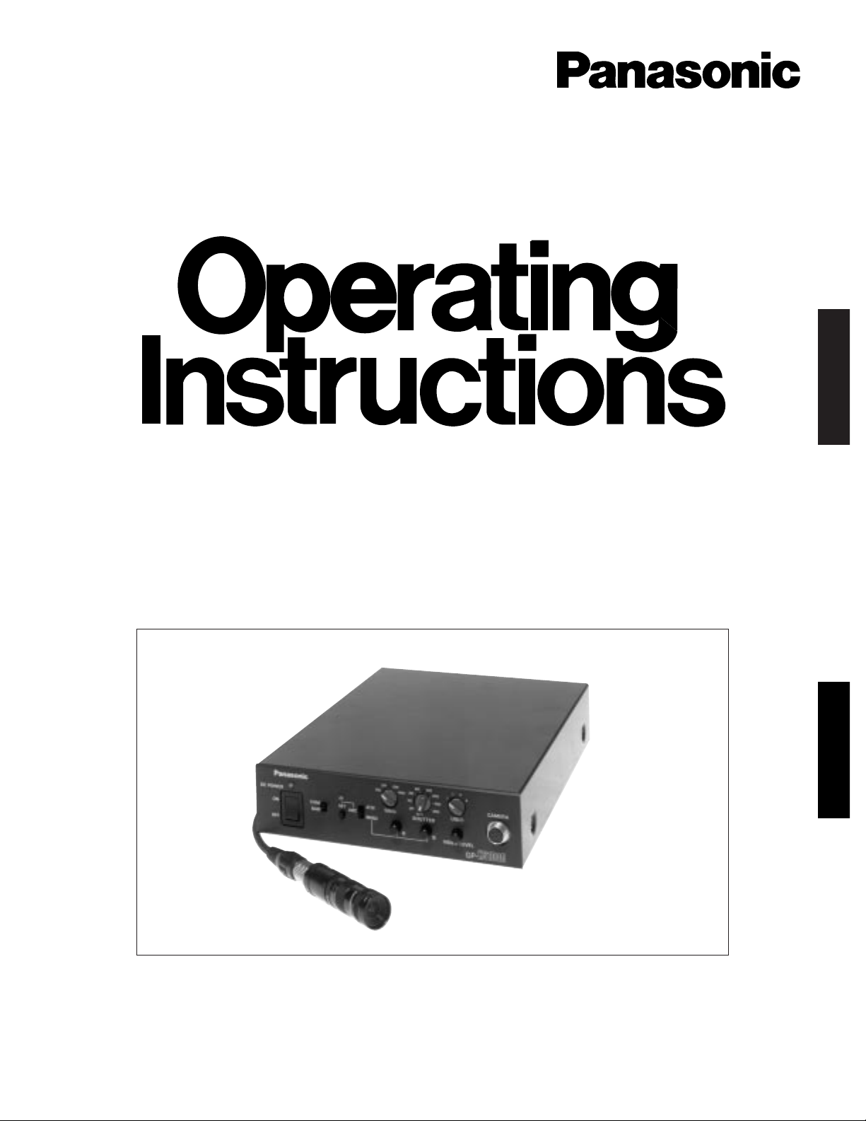
Industrial Colour Camera
GP-KS1000E
(Lens and Cable: option)
Before attempting to connect or operate this product, please read these instructions completely
ENGLISH
DEUTSCH
Page 2

The serial number of this product may be found on the
bottom of the unit.
You should note the serial number of this unit in the
space provided and retain this book as a permanent
record of your purchase to aid identification in the event
of theft.
Model No.
Serial No.
The lightning flash with arrowhead symbol, within an equilateral triangle, is
interned to alert the user to the presence of uninsulated "dangerous voltage" within the product's enclosure that
may be of sufficient magnitude to constitute a risk of electric shock to persons.
The exclamation point within an equilateral triangle is intended to alert the user
to the presence of important operating
and maintenance (servicing) instructions in the literature accompanying the
appliance.
WARNING:
TO PREVENT FIRE OR ELECTRIC SHOCK HAZARD, DO NOT EXPOSE THIS APPLIANCE TO RAIN OR MOIS
TURE.
CAUTION:
TO REDUCE THE RISK OF ELECTRIC SHOCK,
DO NOT REMOVE COVER (OR BACK), NO USER
SERVICEABLE PARTS INSIDE.
REFER SERVICING TO QUALIFIED SERVICE
PERSONNEL.
CAUTION
RISK OF ELECTRIC SHOCK
DO NOT OPEN
ENGLISH VERSION
We declare under our sole responsibility that the product to which
this declaration relates is in conformity with the standards or other
normative documents following the provisions of Directive
EEC/89/336.
Nosotros declaramos bajo nuestra única responsabilidad que el
producto a que hace referencia esta declaración està conforme con
las normas u otros documentos normativos siguiendo las estipulaciones de la directiva CEE/89/336.
Noi dichiariamo sotto nostra esclusiva responsabilità che il prodotto
a cui si riferisce la presente dichiarazione risulta conforme ai
seguenti standard o altri documenti normativi conformi alle disposizioni della direttiva CEE/89/336.
Wij verklaren als enige aansprakelijke, dat het produkt waarop deze
verklaring betrekking heeft, voldoet aan de normen of andere normatieve dokumenten, overeenkomstig de bepalingen van Richtlijn
89/336/EEC.
Vi erklærer os eneansvarlige for, at dette produkt, som denne
deklaration omhandler, er i overensstemmelse med den følgende
standarder eller andre normative dokumenter i følge bestemmelserne i direktiv 89/336/EEC.
Vi deklarerar härmed värt fulla ansvar för att den produkt till vilken
denna deklaration hänvisar är i överensstämmelse med standarddokument, eller andra normativa dokument som framstölls i Direktiv
89/336/EEC.
Ilmoitamme yksinomaisella vastuullamme, että tuote, jota tämä
ilmoitus koskee, noudattaa seuraavia standardeja tai muita ohjeellisia asiakirjoja, jotka noudattavat direktiivin 89/336/EEC. säädöksiä.
Vi erklærer oss alene ansvarlige for at produktet som denne
erklæringen gjelder for, er i overensstemmelse med følgende
normer eller andre normgivende dokumenter som fælger bestemmelsene i direktiv 89/336/EEC.
Nous déclarons sous notre seule responsabilité que le produit
auquel se référe cette déclaration est conforme aux normes ou
autres documents normatif conformément aux dispositions de la
directive 89/336/CEE.
Page 3

-1-
The Panasonic‘s Industrial Digital Signal Processing
Colour Camera GP-KS1000E overcomes space limitations that have many video applications. Weighting only
18 g (0.04 lbs), remarkably compact size of this industri-
al camera is only two-thirds of an inch in diameter and
less than two inches in length. It can be extended up to
10-meter (33 feet) away, using an optional 10-meter (33-
1. 1/2 inch Interline Transfer CCD image sensor with
838 (H) x 1 164 (V) pixels.
2. 560 lines of horizontal resolution.
3. 5 lx (0.5 footcandle) at F1.4 of minimum scene illumination.
4. 54 dB of signal to noise ratio.
5. Selectable Auto Tracing White Balance (ATW), Auto
White Balance Control (AWC) or Manual White
Balance Control.
6. Setting gain AGC or shutter AUTO position enable
to control the video level.
7. DC 12V operation
PREF ACE
FEATURES
feet) cable. With the 1 000 000-element, 1/2-inch CCD
pick-up device, horizontal resolution is more than 560
lines, and signal-to-noise ratio is 54 dB. The Gain
Selection switch at AGC lets you obtain clear, high-quality colour images in light as low as 5 lx (0.5 footcandle)
at F1.4.
8. 10-meter (33-feet) of maximum cable length
between camera head and camera control unit with
optional camera cable.
9. Gen-lock capability.
10. Built-in EBU colour bar generator.
11. RGB and S-Video Outputs are provided.
12. The electronic shutter speed is variable as follows:
Auto (the speed is changed automatically) and has
seven fixed speeds.
13. Four positions to store the settings which can be
changed as required (aperture level, chroma gain,
etc.) by using the User switch.
CONTENTS
PREFACE .................................................................................................................................................................................. 1
FEATURES ................................................................................................................................................................................ 1
PRECAUTIONS ......................................................................................................................................................................... 2
SYSTEM BLOCK DIAGRAM ..................................................................................................................................................... 3
MAJOR OPERATING CONTROLS AND THEIR FUNCTIONS ................................................................................................... 3
PREPARATION ......................................................................................................................................................................... 7
INSTALLATION ........................................................................................................................................................................ 8
CONNECTIONS ......................................................................................................................................................................... 9
USER FILE SETTING .............................................................................................................................................................. 10
PREVENTION OF BLOOMING AND SMEARING ................................................................................................................... 11
SPECIFICATIONS ................................................................................................................................................................... 12
OPTIONAL ACCESSORIES .................................................................................................................................................... 12
ENGLISH
Page 4

-2-
• Do not attempt to disassemble the camera or the
camera control unit.
To prevent electric shock, do not remove screws or
cover. There are no user-serviceable parts inside.
Refer servicing to qualified service personnel.
• Do not expose the camera or camera control unit to
rain or moisture, or do not try to operate it in wet
conditions.
Take immediate action if the camera or camera control unit becomes wet. Turn power off and refer servicing to qualified service personnel.
Moisture can damage the camera and camera control unit and can cause electric shock.
• Ambient Temperature range
Do not install the camera in the place where the
temperature is beyond –10°C - +40 °C (14 °F - 104
°F).
• Never crush or pinch the camera cable.
Don't wind or bend the camera cable into a small
circle.
• Never face the camera toward the sun, whether in
use or not.
Use caution when operating the camera in the vicinity of spot lights or other lights and light reflecting
apparatus.
• Maintenance
After pressing the DC Power ON/OFF switch off,
clean it with a dry cloth. If it is difficult to clean it of
dirt or dust, use a cloth with detergent.
Use the lens cleaning tissue paper (may be available at your local camera store) for lens cleaning.
• Connect this to a DC12V, CLASS 2 power supply
only.
• After using the camera, turn off the DC Power
ON/OFF Switch and put the lens cap on the camera
head.
• Connect together only the camera head and the
camera control unit which are packed in the same
box (a pair). Otherwise it may cause improper operation.
• Every necessary procedures with regard to installation should be made by qualified service personnel
or system installer.
Caution:
Connecting or disconnecting camera cable to/from
the camera control unit or the camera must be done
after turning the DC Power ON/OFF Switch to the OFF
position. Failure to do this may damage the camera
head.
PRECAUTIONS
Page 5
CAMERA
DC POWER
ON
OFF
SET
AWC
ATW
MANU
R B
VIDEO LEVEL
GP-
KS1000
AGC
OFF LOW
HIGH
OFF
120
250
500 1000
2000
4000
8000
AUTO
SHUTTER
1234
USER
CAM
BAR
GAIN
FOC
US
LOC
K
FOCUS LOCK
#3 #4 #5
-3-
Camera Control Unit
Camera Head with Optional Lens
CAMERA
DC POWER
ON
OFF
SET
AWC
ATW
MANU
R B
VIDEO LEVEL
GP-
KS1000
AGC
OFF LOW
HIGH
OFF
120
250
500 1000
2000
4000
8000
AUTO
SHUTTER
1234
USER
CAM
BAR
GAIN
q
i
e t y u o !0 !2
!1
w r
S-VIDEO OUT
VIDEO OUT G/L IN
OFF
ON
75
Ω
EVR
DC 12V IN
RGB/SYNC OUT
!3 @5@6@7@8@9#0#1
#2
!4 !5 !6
!8
!7 !9
@0
@2
@4
@1
@3
0
F
E
D
C
B
A
9
8
7
6
5
4
3
2
1
0
F
E
D
C
B
A
9
8
7
6
5
4
3
2
1
Camera Cable
GP-CA1K/2: 2m
GP-CA1K/3: 3m
GP-CA1K/38: 3.8m
GP-CA1K/10: 10m
Camera Control Unit
Camera Head
GP-KS1000 Series Standard Configuration
Camera Head, Camera Control Unit.
Wide Angle Lens
GP-LM7TA
Tele Angle Lens
GP-LM15TA
Optional Accessories
Pinhole Lens
GP-LP12TA
C-Mount Adaptor
GP-AD22TA
Tele Angle Lens
GP-LM24TA
Camera Holder
GP-AD1K
SYSTEM BLOCK DIAGRAM
MAJOR OPERATING CONTROLS AND THEIR FUNCTIONS
Page 6

-4-
Camera Control Unit
q Power Indicator
The indicator lights up red when the DC power
On/Off switch w is turned on.
w DC Power On/Off Switch (DC POWER, ON/OFF)
This switch controls power to the unit and the camera.
e Camera/Colour Bar Selection Switch (CAM/BAR)
This switch is used to select either camera pictures
or EBU colour bars to be supplied to the video output connector (VIDEO OUT), Y/C output connector
(S-VIDEO OUT), or RGB output connector (D-SUB,
9-pin).
CAM: To supply camera pictures.
BAR: To supply EBU colour bars. Set the switch to
the bar position when making video monitor
adjustments or recording colour bar signals.
r AWC Set Button (AWC SET)
The white balance can be set by pressing this button when the White Balance Selection Switch y is
set to the AWC position.
t White Balance Indicator
This indicator blinks while the white balance is being
automatically set. This indicator lights continuously
when the white balance is set improperly. In this
case, carry out the auto white balance setting procedure.
y White Balance Selection Switch (ATW/AWC/
MANU)
ATW: In this Auto-Tracing White Balance (ATW)
position, the colour temperature of the illuminant
is continuously monitored and the white balance of the camera is automatically set.
AWC: This switch is used to set the Auto White
Balance (AWC) together with AWC Set Button r.
Note: When the White balance Offset On/Off Switch
@8 is turned on, the fine adjustment for R/B Gain
Controls i is available after completing the white
balance setting.
MANU: The R/B gain of the white balance can be
adjusted manually by means of the R/B Gain
Controls i.
u Gain Selection Switch (AGC / OFF / LOW / HIGH)
This switch is used to select a gain level of the video
amplifier as follows:
i R / B Gain Controls (R/B)
These controls are use to adjust the R and B gain of
the white balance.
These controls are available only when the White
Balance Offset On/Off Switch @8 is turned on in the
AWC or MANU mode.
o Electronic Shutter Switch (AUTO, OFF, 1/120,
1/250, 1/500, 1/1 000, 1/2 000 ,1/4 000, 1/8 000)
AUTO: In this position, the electronic shutter speed
is changed automatically to obtain the proper
video level according to the light condition.
Target value of the shutter speed can be adjusted manually by using Video Level Control !1.
OFF: In this position, the electronic shutter is turned
off.
1/120-1/8 000: Seven fixed electronic shutter
speeds are available from 1/120 -1/8 000.
!0 User Switch (USER)
• When AWC setting is made by pressing AWC
Set Button r, AWC setting is stored on the
selected position of this switch.
The stored AWC settings are only available
when the White Balance Selection Switch y is
set at AWC.
• User File Setting is adjustable and is saved in
the memory by User File Set Switch @1, User File
Item Switch @2, User File Adjust Control @3, and
User File Select Switch @44 may be used in up to
four ways.
Refer User File Setting on page 9 for more details.
!1 Video Level Control (VIDEO LEVEL)
The standard video level can be adjusted when the
Gain Selection Switch u is set at AGC or the
Electronic Shutter Switch o is set at AUTO.
!2 Camera Cable Connector (CAMERA)
This 20-pin connector is used for connection of the
optional camera cable.
Caution: Connecting or disconnecting the camera
cable must be done after turning off the DC
Power On/Off Switch w.
!3 RGB/SYNC Output Connector (D-SUB, 9-PIN)
(RGB/SYNC OUT)
The red, green, blue, sync and composite video signals are provided at this connector.
5
9
6
1
RGB/SYNC OUT (D-SUB, 9-pin)
Position of the Switch Gain
AGC Maximum +18 dB
+18 dB
+ 9 dB
0 dB
HIGH
LOW
OFF
MANU
Page 7
-5-
Pin No. Description
Ground (GND)1
Ground (GND)2
Red (R) Output (0.7 V [p-p] /75 Ω)3
Green (G) Output (0.7 V [p-p] /75 Ω)4
Blue (B) Output (0.7 V [p-p] /75 Ω)5
Composite Video Output (1.0 V [p-p] /75 Ω)6
Sync (SYNC) Output (0.3 V [p-p] /75 Ω)7
Ground (GND)8
Ground (GND)9
!5 Video Output Connector (VIDEO OUT)
A 1.0 V[p-p] composite video signal is provided at
this connector.
!6 Gen-lock Input Connector (G/L IN)
The colour video signal of the camera is automatically synchronized to the gen-lock signal
(Composite Signal, Black Burst Signal or Video
Sync) when either signal is supplied to this connector.
Caution: If a camera picture supplied from this
connector, such as a VTR playback picture,
appears jittery on the screen, proper camera
picture synchronization cannot be obtained.
!7 Gen-lock Video 75 Ω Termination On/Off Switch
(75 Ω ON/OFF)
When the gen-lock video signal is looped through
the BNC “T” adopter, set this switch to the OFF
position. If it is not through the BNC “T” adapter, set
this switch to the ON position.
!8 EVR Adjustment Connector
Connect the EVR to this connector.
Normally, keep the connector covered with the rubber cap.
!9 DC 12V Input Terminals (DC 12V IN)
These terminals accept an external DC source supplying nominal power of 12V, 0.7A -1A.
!4 S-Video Output Connector (S-VIDEO OUT)
The luminance (Y) and chroma (C) signals for SVHS VTR or monitor are provided at this connector.
Pin Configuration
423
1
DescriptionPin No.
Y Ground (GND)1
C Ground (GND)2
Y Signal Output: 0.7 V [p-p] (Y level / 75 Ω)3
C Signal Output: 0.3 V [p-p] (burst level / 75 Ω)4
@0 User File Set Indicator
This indicator show the setting steps of the User File
Set as follows:
Setting Indicator
is on process Blinks
is completed Goes off after blinking
is incomplete Lights up
@1 User File Set Switch
This switch is used to change and memorize the
setting of User File Set Function.
@2 User File Item Switch
This switch is used to select a User File Setting item.
Refer to User File Setting on page 10 for selectable
items..
@3 User File Adjust Control
This switch is used to adjust the value of an item
selected with the User File Item switch.
@4 User File Select Switch
This switch selects the setting of SC Coarse (item
No.1) or the sensing zone (item No.7).
@5 User File Set On/Off Switch
This switch is used to activate the User File Setting
Function. When this switch is set to ON, User File
Item switch @2, User File adjust control @3, and User
File select switch @4 are available to set the User
File Settings Function.
@6 This switch is preset at the factory.
Fix this switch to the OFF position.
@7 PEAK / AVE Switch
This switch is used to select AGC and ELC detection levels. Set the switch to ON to select PEAK
detection, or to OFF to select AVERAGE detection.
The video level can be changed using the Video
Level Control !1 on the front panel.
Normally, set this switch to OFF.
@8 White Balance Offset On/Off Switch
By turning on this switch, the white balance offset in
the AWC can be adjusted to a fine level by using the
R/B Gain Controls i.
Normally, keep this switch in the ON position.
on
off
on
off
on
off
on
off
Cautions:
• Connect this to a DC 12 V class 2 power supply
only.
• To prevent fire or electric shock hazard, the UL
listed wire VW-1 style 1007 should be used for
the cable for DC 12V Input Terminal.
Page 8
-6-
Note: Make certain switch settings are correct for
the cable length.
If the camera length is incorrect, camera pictures may not be displayed properly.
Cable Switch #1 Cable Switch #2 Cable (length)
OFF OFF GP-CA1K/2 (2m)
ON OFF GP-CA1K/3 (3m)
OFF ON GP-CA1K/38 (3.8m)
ON ON GP-CA1K/10 (10m)
@9 This switch is preset at the factory.
Fix this switch to the ON position.
#0 This switch is preset at the factory.
Fix this switch to the OFF position.
#1/#2 Cable Switch
These switches are provided for the optional cables.
Set the switches according to the length of the
optional cables as follows:
on
offonoff
on
off
Camera Head with Optional Lens
#3 Manual Iris Control Ring
This ring is used to adjust the lens iris manually.
#4 Focus Ring
This ring is used to adjust the focus of the picture.
To adjust the focus, loosen the Focus Lock Ring #5
by rotating it clockwise (viewed from the front of the
camera) and turn the Focus Ring until the picture
becomes focused. Secure the Focus Ring by rotating the Focus Lock Ring #5 counterclockwise.
#5 Focus Lock Ring
This ring is used to secure the Focus Ring #4.
Page 9
-7-
Caution: Keep the DC Power ON/OFF switch of the
camera control unit in the OFF position through the
installation.
Camera Head with GP-LM7TA, GPLM15TA, GP-LM24TA or GP-LP12TA
1. Remove the body cap of the camera and confirm
that the surface of the optical filter of the camera
head is clean.
If the surface of the optical filter is not clean, use a
blower brush or lens cleaning tissue.
2. Rotate the focus lock ring fully clockwise.
Mount the Pinhole Lens, Wide-angle Lens or Teleangle Lens to the camera by rotating it clockwise
slowly.
Body Cap
Focus Lock Ring
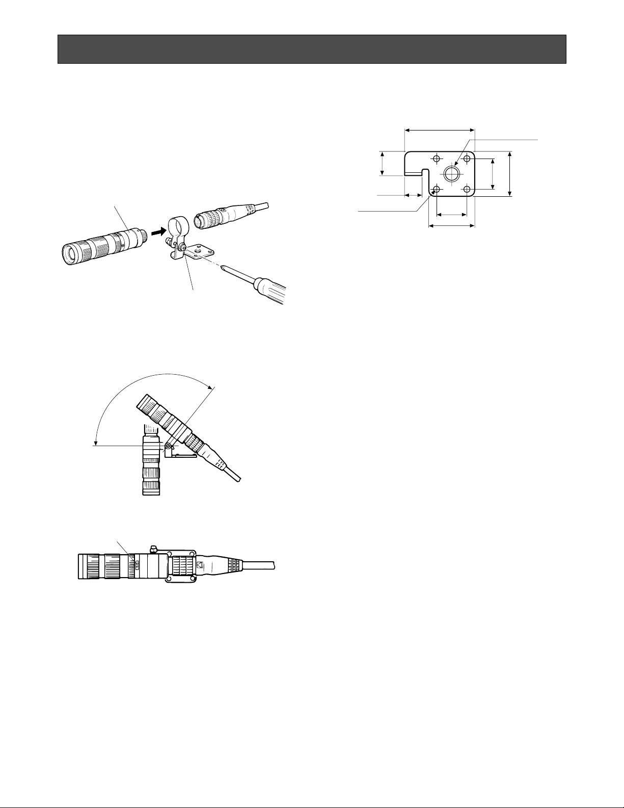
PREPARATION
Camera Head with GP-AD22TA and optional C-mount lens
1. Remove the body cap of the camera head and confirm that the surface of the optical filter of the camera head is clean.
If the surface of the optical filter is not clean, use a
blower brush or lens cleaning tissue.
2. Attach the optional C-mount lens to the C-mount
adapter GP-AD22TA by rotating it clockwise.
3. Rotate the focus lock ring fully.
Mount the lens and C-mount adapter by rotating
them clockwise slowly.
Caution: If the optional C-mount lens size exceeds
50mm (2”) in diameter, 70mm (2-3/4”) in length
and 300 g (0.66 lbs) in weight, both the camera
and lens should be secure.
Body Cap
Focus Lock Ring
Page 10
-8-
The camera head can be installed on the ceilling, wall
or etc. by using the threaded 1/4”-20 UNC screw hole
of the camera holder (optional accessory).
1. Loosen the screw of the camera holder until it is
tight and insert the camera head into it as shown
below.
2. Adjust the tilt angle and rotation of the camera head
and secure the camera and camera holder by tightening the screw.
3. Install the camera with camera holder onto the tripod or other mounting bracket.
Caution: If the optional C-mount lens size exceeds
50mm (2”) in diameter, 70mm (2-3/4”) in length
and 300g (0.66 lbs) in weight, both the camera
and lens should be secure.
Holding position
Screw
Approx.
130°
Marker (Red, Green, Blue)
31.5 (1-1/4”)
1/4”-20UNC
8 (5/16”)
11
(7/16”)
14
(9/16”)
20
(3/4”)
14
(9/16”)
20 (3/4”)
4-φ3.3 (4-φ1/8”)
Unit: mm (inches)
INSTALLATION
Page 11

-9-
Cautions:
• Keep the DC Power ON / OFF switch in the OFF
position until all connections have been properly
made.
• Connect the enclosed camera head and the camera control unit in the same package. Connecting
other models may cause malfunctions.
Internal Sync Operation
1. Connect the camera cable between the camera
head and control unit.
2. Connect the coaxial cable with the BNC connectors
between the Video Output Connector of the camera
control unit and the video monitor or VTR.
3. Connect the power cable from the 12 V DC input
terminal to a 12 V DC power supply unit (purchasable locally).
• Calculation method of maximum cable length
between camera control unit and the power supply
unit is as follows:
11.5V DC < VA - (R x 0.42 x L) < 16V DC
L: Cable length (meter)
R: Resistance of copper wire (Ω / meter)
VA: DC output voltage of power supply unit
L standard = VA – 12 / 0.42 x R (meter)
L minimum = VA – 16 / 0.42 x R (meter)
L maximum = VA – 11.5 / 0.42 x R (meter)
Using coaxial cables with BNC connectors, connect the
video output connector of the camera control unit to the
video input connector of a Special Effects Generator
(SEG) (purchasable locally) and the G/L input connector
of the camera control unit to the black burst output of
the SEG.
Cautions:
• Connect this to a DC 12 V class 2 power supply
only.
• To prevent fire or electric shock hazard, the UL listed wire VW-1 style 1007 should be used for the
cable for DC 12V Input Terminal.
Cautions:
• Connect this to a DC 12 V class 2 power supply
only.
• To prevent fire or electric shock hazard, the UL listed wire VW-1 style 1007 should be used for the
cable for DC 12V Input Terminal.
Gen-lock Operation
Connect the camera head and the camera control unit
with the camera cable.
IN
OUT
VIDEO
Hi-Z75Ω
IN
OUT
VIDEO
Hi-Z75Ω
S-VIDEO OUT
VIDEO OUT G/L IN
OFF
ON
75
Ω
EVR
1
2
3
4
5
6
7
8
9
0
1
2
3
4
5
6
7
8
9
0
DC 12V IN
RGB/SYNC OUT
Video
Monitor
VTR or
Video Monitor
Coaxial
Cable
CCU
S-VIDEO OUT
VIDEO OUT G/L IN
OFF
ON
75
Ω
EVR
1
2
3
4
5
6
7
8
9
0
1
2
3
4
5
6
7
8
9
0
DC 12V IN
RGB/SYNC OUT
S-VIDEO OUT
VIDEO OUT G/L IN
OFF
ON
75
Ω
EVR
1
2
3
4
5
6
7
8
9
0
1
2
3
4
5
6
7
8
9
0
DC 12V IN
RGB/SYNC OUT
CCU
CCU
75Ω set to ON
Video Out
75Ω set to ON
G/L In
Video Out
G/L In
Video In
Black Burst
Out
Special Effects Generator
(SEG)
CONNECTIONS
Page 12

-10-
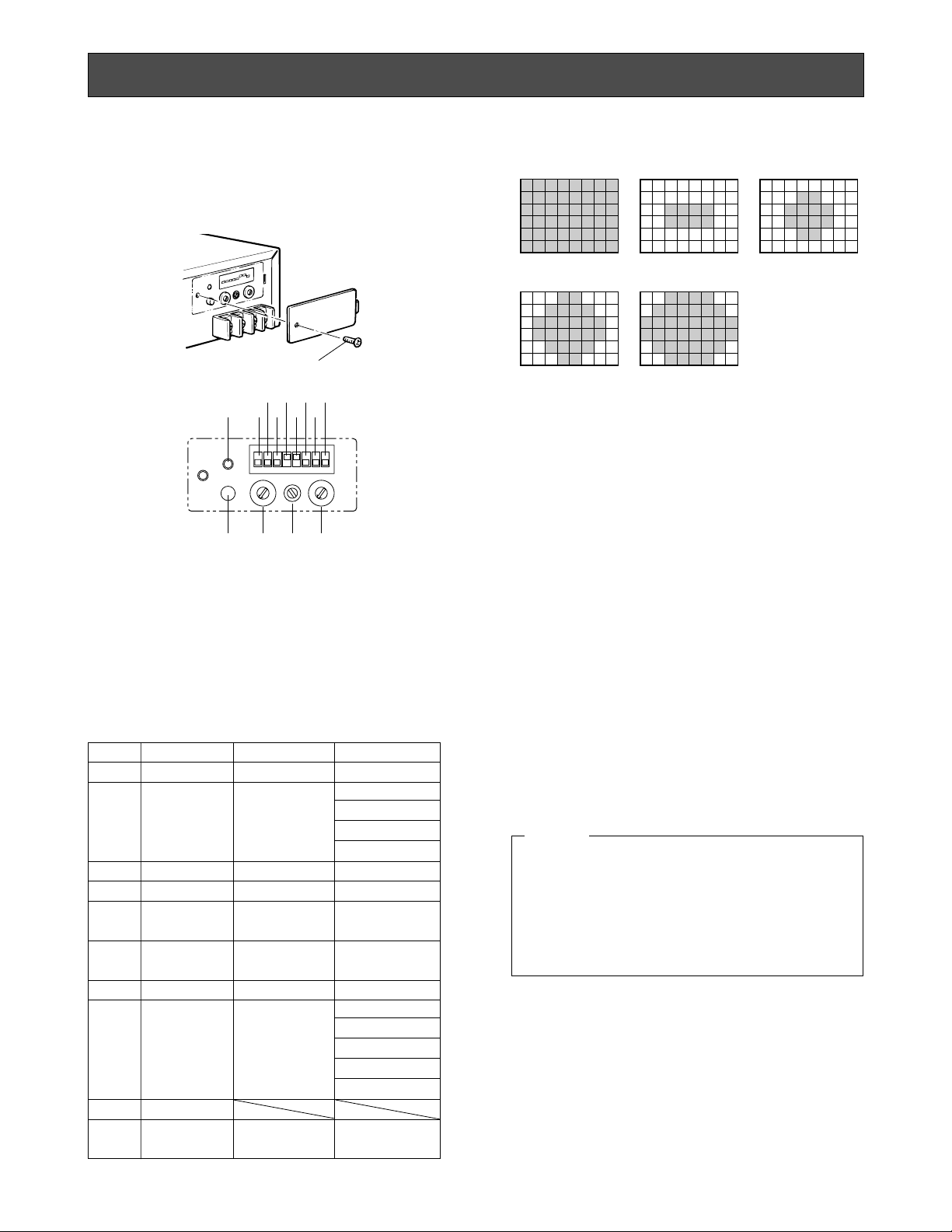
User preference stored can be accessed by selecting
user switch.
1. Remove the switch cover on the rear of the camera
control unit by removing the screw.
8 (NC)
9
Reset All
Settings
Invalid Invalid
7
AGC/ELC
Sensing Zone
Invalid
0: ALL
1: CENTRE
2: S CIRCLE
3: M CIRCLE
4: L CIRCLE
Item No.
Item Adjust control
@3
Select switch
@4
0
G/L H Phase Valid Invalid
1
G/L SC
Coarse/Phase
Valid
Valid 0:0°
1:90°
2:180°
3:270°
2 DTL Level Valid Invalid
3 Chroma Gain Valid Invalid
4
Colour Matrix
(R-G)
Valid Invalid
5
Colour Matrix
(B-G)
Valid Invalid
6 Pedestal Level Valid Invalid
AGC/ELC Sensing Zone (Item No. 7)
0:ALL 1:CENTRE 2:S CIRCLE
3:M CIRCLE 4:L CIRCLE
Note: Item 1 and 2 settings are not stored at each user
file distinctively.
5. Select or adjust the level of each item by the User
File Select switch @4 or User File Adjust control @3.
6. Press User File Set switch @1 to store the adjusted
value in the memory.
7. Repeat the above steps 4 to 6 set the other items.
8. After all the necessary items have been set, set Use
File Set ON/OFF Switch @5 to OFF.
9. Place the switch cover back on the switch panel on
the rear of the camera control unit and fasten it with
the screws.
2. Select a desired user file (1 - 4) by turning User
Switch !0 on the front panel.
3. Set User File Set On/Off Switch @5 on the rear panel
to ON.
4. Select an item for adjustment by turning User File
Item Switch @2 on the rear panel.
The item numbers and the corresponding items are
shown below.
Do not set User File Item switch @2 to A through F
positions.
If A to F is selected, use both User File Item switch @2
and User File Select switch @4 to the position F, then
press User File Set switch @1.
Caution
0
1ON2 3 4 5 6 7 8
@2 @3 @4@1
@5
@7 @9 #1
#2#0@8@6
@0
F
E
D
C
B
A
9
8
7
6
5
4
3
2
1
0
F
E
D
C
B
A
9
8
7
6
5
4
3
2
1
Screw
USER FILE SETTING
Page 13

-11-
When the camera is aimed towards spotlights or other
bright lights or light reflecting objects, smearing or
blooming may appear. Therefore the camera should be
used carefully in the vicinity of extremely bright objects
to avoid smearing or blooming.
If the camera is aimed at the sun or very bright light,
such as a laser beam, for a long period of time, the
CCD image sensor may become damaged and blemishes (white or black dots) may appear on the monitor
screen.
,
,
,,
,,
Smear
Bright object
Ring type flare
PREVENTION OF BLOOMING AND SMEARING
Page 14

-12-
Image Sensor: 1 / 2“ interline transfer (IT) CCD image sensor
Pixels: 838 (Horizontal) x 1 164 (Vertical)
Scanning Standard: 625 lines, 50 fields, 25 frames
Synchronizing System: Internal or External (Gen-lock), automatically switchable PAL standard
External (Gen-lock) Input: VBS / VS is selectable
Video Output: Video Output : BNC Connector x 1
1.0 V [p-p] PAL composite / 75 Ω
Y/C (S-VIDEO) Output : S-VIDEO Connector x 1
0.7 V [p-p] Luminance level (Y) / 75 Ω (S-VIDEO connector)
0.3 V [p-p] Burst level (C) / 75 Ω (S-VIDEO connector)
RGB / SYNC Output : D-SUB 9-pin Connectors x 1
R / G / B : 0.7 V [p-p] each / 75 Ω
SYNC : 0.3 V [p-p] / 75 Ω selectable
Required Illumination: 2000 lx at F5.6, 3200 K
Minimum Illumination: 5 lx (0.5 fc) at F1.4 with +18dB gain, 30 IRE level
Signal to Noise Ratio: 54 dB (Typical luminance) without aperture and gamma
Horizontal Resolution: 560 lines at center (Y signal)
White Balance: ATW (Automatic Tracing White Balance Control), AWC (Automatic White Balance
Control) and Manual
Colour Bar: Built-in EBU colour bar
Electronic Shutter: Selectable : AUTO, 1/120, 1/250, 1/500, 1/1000, 1/2000, 1/4000 and 1/8000
Gain Selection: AGC and Gain Up (OFF / LOW / HIGH)
Switches: Power On/Off (POWER), Camera / Colour Bar Selection (CAM / BAR), Gain Selection
(AGC / OFF / LOW / HIGH (0 / +9 / +18dB)), Auto White Balance Set (AWC SET),
White Balance Selection (ATW / AWC / MANU), Shutter Speed Selection,
User File Selection (1 / 2 / 3 / 4)
Controls: R gain, B gain and VIDEO Level
Lens Mount: Special Mount
Power Source: 12V DC, 700 mA
Ambient Operating Temperature: −10°C - +40°C
Ambient Operating Humidity: 30 %- 90%
Dimensions: Camera Head (Excluding Lens and Body Cap):
17 mm (Diameter) x 42 mm (11/16” x 1-5/8”)
Camera Control Unit (Excluding Rubber Feet and Connectors):
170 (W) x 43.5 (H) x 227 (D) mm (4-11/16”(W) x 1-7/16”(H) x 6-1/8”(D))
Weight : Camera Head (Including Body Cap): 18 g (0.04 lbs)
Camera Control Unit: 1.3 kg (2.86 lbs)
Weight and dimensions indicated are approximate.
Specifications are subject to change without notice.
SPECIFICATIONS
• Camera Cable GP-CA1K/2, GP-CA1K/3, GP-CA1K/38 or GP-CA1K/10
• C-mount Adaptor GP-AD22TA
• Wide Angle Lens GP-LM7TA
• Pinhole Lens GP-LP12TA
• Tele Angle Lens GP-LM15TA or GP-LM24TA
• Camera Holder GP-AD1K
OPTIONAL ACCESSORIES
Page 15

-13-
DEUTSCHE AUSGABE
(GERMAN VERSION)
INHALT
VORWORT .............................................................................................................................................................................. 14
MERKMALE ............................................................................................................................................................................ 14
VORSICHTSMASSNAHMEN ................................................................................................................................................... 15
SYSTEMBLOCKSCHALTBILD ................................................................................................................................................ 16
WICHTIGE BEDIENUNGSELEMENTE UND IHRE FUNKTIONEN .......................................................................................... 16
VORBEREITUNG .................................................................................................................................................................... 20
INSTALLATION ....................................................................................................................................................................... 21
ANSCHLÜSSE ........................................................................................................................................................................ 22
ANWENDERDATEI-EINSTELLUNG ........................................................................................................................................ 23
VERMEIDUNG VON ÜBERSTRAHLEN UND LEUCHTFAHNEN ............................................................................................. 24
TECHNISCHE DATEN ............................................................................................................................................................ 25
SONDERZUBEHÖR ................................................................................................................................................................ 25
Die in dieser Bedienungsanleitung aufgeführten Modellnummern weisen keinen Anhang auf.
Das Blitzzeichen mit Pfeil im gleichseitigen Dreieck soll den Benutzer auf das
Vorhandensein von nichtisolierter "gefährlicher Spannung" innerhalb des Gehäuses hinweisen, die so groß sein
kann, daß sie Gefahr eines elektrischen
Schlags darstellt.
Das Ausrufezeichen im gleichseitigen
Dreieck soll den Benutzer auf wichtige
Bedienungs- und Wartungsanweisungen in den Unterlagen hinweisen, die
dem Gerät beiliegen.
Die Fabriknummer dieses Gerätes ist auf dessen Bodenabdeckung angegeben.
Sie sollten die Fabriknummer dieses Gerätes in den
dafür vorgesehenen Raum eintragen und diese
Anleitung als Kaufsunterlage aufbewahren, um im Falle
eines Diebstahls die ldentifizierung zu erleichtern.
Modellnummer
Fabriknummer
WARNUNG: UM DIE GEFAHR VON BRAND ODER STROMSCHLAG ZU VERHÜTEN, DIESES GERÄT WEDER REGEN
NOCH FEUCHTIGKEIT AUSSETZEN.
WARNUNG:
WEDER DECKEL NOCH RÜCKPLATTE ABNEHMEN,
UM DIE GEFAHR EINES ELEKTRISCHEN SCHLAGS
ZU VERMEIDEN. DAS GERÄT ENTHÄLT KEINE
BAUTEILE, DIE VOM KUNDEN GEWARTET WERDEN
KÖNNEN.
CAUTION
RISK OF ELECTRIC SHOCK
DO NOT OPEN
DEUTSCH
Wir erklären in alleiniger Verantwortung, daß das Produkt, auf das
sich diese Erklärung bezieht, mit der folgenden Normen oder
normativen Dokumenten übereinstimmt.
Gemäß den Bestimmungen der Richtlinie 89/336/EEC.
Page 16

-14-
Die industrielle Farbkamera mit Digital-Signalverarbeitung GP-KS1000E von Panasonic macht Schluß mit
Raumbegrenzungen, die viele Video-Applikationen
erschwert haben. Mit einem Gewicht von nur 18 g, weist
diese extrem kompakte industrielle Kamera einen
Durchmesser von nur 17 mm und eine Länge von nur
43 mm auf. Unter Verwendung eines als Sonderzubehör
erhältlichen Kamerakabels kann die Kamera in einer
Entfernung von bis zu 10 m von der Kamerasteuer-
1. 1/2-Zoll CDD-Bildsensor mit Zwischenzeilenübertragung und 838 (H) x 1 164 (V) Pixel.
2. Horizontale Auflösung 560 Zeilen.
3. Minimale Szenenbeleuchtung beträgt 5 Lux bei
F1,4.
4. Rauschabstand 54 dB.
5. Auto-Tracing-Weißbalance (ATW), Auto-Weißbalance-Regelung (AWC) oder manuelle Weißbalance-Regelung wählbar.
6. Automatische Gewinnregelung und Verschlußzeit
können auf Position AUTO eingestellt werden, um
automatische Steuerung des Videopegels zu erhalten.
7. 12 V Gleichstrombetrieb.
VORWORT
MERKMALE
einheit installiert werden. Mit 1 000 000 Pixel gewährleistet der 1/2-Zoll CCD-Bildsensor eine horizontale Auflösung von mehr als 560 Zeilen und einen Rauschabstand von 54 dB. Bei auf AGC (automatische Gewinnregelung) gestelltem Gewinnwahlschalter werden
hochwertige Bilder bei einer Beleuchtung von nur 5 Lux
(bei F1,4) erhalten.
8. Maximale Kabellänge zwischen dem Kamerakopf
und der Kamerasteuereinheit 10 Meter mit dem
optionalen Kamerakabel.
9. Taktsynchronisierung möglich.
10. Eingebauter EBU-Farbbalkengenerator.
11. RGB- und S-Video-Eingänge vorhanden.
12. Die elektronische Verschlußzeit ist wie folgt variabel:
Auto (die Verschlußzeit wird automatisch geändert)
und sieben feste Zeiten.
13. Vier Positionen für die Speicherung der Einstellungen, die gemäß Anforderungen (Blendenpegel,
Chromagewinn usw.) mit Hilfe des Anwenderschalters in Abhängigkeit von der Situation geändert
werden können.
Page 17

-15-
• Die Kamera oder die Kamerasteuereinheit niemals
zerlegen.
Niemals Schrauben oder Abdeckungen entfernen,
um elektrische Schläge zu vermeiden. Im Inneren
befinden sich keine vom Anwender zu wartenden
Teile. Wartungsarbeiten nur von qualifiziertem Wartungspersonal ausführen lassen.
• Die Kamera oder die Kamerasteuereinheit niemals
Regen oder Feuchtigkeit aussetzen und auch niemals an einem nassen Ort betreiben.
Falls die Kamera oder die Kamerasteuereinheit naß
wird, sofort die Stromversorgung ausschalten und
von einem qualifizierten Wartungstechniker warten
lassen.
Feuchtigkeit kann die Kamera und die Kamerasteuereinheit beschädigen und zu elektrischen
Schlägen führen.
• Zulässiger Temperaturbereich
Die Kamera niemals an einem Ort installieren, an
dem die Temperatur außerhalb des zulässigen
Bereichs von −10°C bis +40°C liegt.
• Das Kamerakabel nicht abdrücken oder einklemmen.
Das Kamerakabel niemals zu stark abbiegen oder in
einer engen Spule aufspulen.
• Niemals die Kamera auf die Sonne richten, ob diese
nun eingeschaltet ist oder nicht.
Vorsicht ist geboten, wenn die Kamera in der Nähe
von Punktleuchten oder anderen starken Leuchten
bzw. lichtreflektierenden Apparaten verwendet wird.
• Wartung
Nachdem der Gleichstrom-Ein/Aus-Schalter ausgeschaltet wurde, den Kamerakopf und die Kamerasteuereinheit mit einem trockenen Tuch reinigen.
Hartnäckig anhaftender Schmutz oder Staub ist mit
einem in neutralem Reinigungsmittel angefeuchteten (nicht nassen!) Tuch zu entfernen.
Für das Reinigen des Objektivs ist im Fachhandel
erhältliches Objektiv-Reinigungspapier zu verwenden.
• Nur an eine 12 V Gleichstromversorgung der Klasse
2 anschließen.
• Nach der Verwendung der Kamera, den Gleichstrom-Ein/Aus-Schalter ausschalten und den
Objektivdeckel an dem Kamerakopf anbringen.
• Nur den in der gleichen Schachtel (als Paar)
verpackten Kamerakopf mit der Kamerasteuereinheit verbinden. Anderenfalls kann es zu Fehlbetrieb kommen.
• Alle erforderlichen Vorgänge hinsichtlich der Installation sollten nur von qualifiziertem Wartungs- oder
Kundendienstpersonal ausgeführt werden.
Vorsicht:
Anschließen oder Abtrennen des Kamerakabels an
die/von der Kamerasteuereinheit und dem Kamerakopf ist nur nach dem Ausschalten des GleichstromEin/Aus-Schalters der Kamerasteuereinheit gestattet.
Anderenfalls kann der Kamerakopf beschädigt werden.
VORSICHTSMASSNAHMEN
Page 18

CAMERA
DC POWER
ON
OFF
SET
AWC
ATW
MANU
R B
VIDEO LEVEL
GP-
KS1000
AGC
OFF LOW
HIGH
OFF
120
250
500 1000
2000
4000
8000
AUTO
SHUTTER
1234
USER
CAM
BAR
GAIN
FOC
US
LOC
K
FOCUS LOCK
#3 #4 #5
-16-
Kamerasteuereinheit
Kamerakopf und optionales Objektiv
CAMERA
DC POWER
ON
OFF
SET
AWC
ATW
MANU
R B
VIDEO LEVEL
GP-
KS1000
AGC
OFF LOW
HIGH
OFF
120
250
500 1000
2000
4000
8000
AUTO
SHUTTER
1234
USER
CAM
BAR
GAIN
q
i
e t y u o !0 !2
!1
w r
S-VIDEO OUT
VIDEO OUT G/L IN
OFF
ON
75
Ω
EVR
DC 12V IN
RGB/SYNC OUT
!3 @5@6@7@8@9#0#1
#2
!4 !5 !6
!8
!7 !9
@0
@2
@4
@1
@3
0
F
E
D
C
B
A
9
8
7
6
5
4
3
2
1
0
F
E
D
C
B
A
9
8
7
6
5
4
3
2
1
Kamerakabel
GP-CA1K/2: 2 m
GP-CA1K/3: 3 m
GP-CA1K/38: 3,8 m
GP-CA1K/10: 10 m
Kamerasteuereinheit
Kamerakopf
Standard-Konfiguration der GP-KS1000 Serie
Kamerakopf und Kamerasteuereinheit
Weitwinkelobjektiv
GP-LM7TA
Teleobjektiv
GP-LM15TA
Sonderzubehör
Lochkamera
GP-LP12TA
C-Fassungs-Adapter
GP-AD22TA
Teleobjektiv
GP-LM24TA
Kamerahalter
GP-AD1K
SYSTEMBLOCKSCHALTBILD
WICHTIGE BEDIENUNGSELEMENTE UND IHRE FUNKTIONEN
Page 19

Position des Schalters
-17-
Kamerasteuereinheit
q Stromversorgungs-Kontrolleuchte
Diese Kontrolleuchte leuchtet rot auf, wenn der
Gleichstrom-Ein/Aus-Schalter w eingeschaltet ist.
w Gleichstrom-Ein/Aus-Schalter (DC POWER,
ON/OFF)
Mir diesem Schalter wird die Stromversorgung der
Kamera und der Kamerasteuereinheit ein- und ausgeschaltet.
e Kamera/Farbbalken-Wahlschalter (CAM/BAR)
Diese Wahlschalter wird verwendet, um entweder
das Kamerabild oder das EBU-Farbbalkensignal zu
wählen, das an dem Video-Ausgangssteckverbinder
(VIDEO OUT), Y/C-Ausgangssteckverbinder (SVIDEO OUT) oder RGB-Ausgangssteckverbinder
(D-SUB, 9-Stift) ausgegeben wird.
CAM: Das Kamerabild wird ausge-geben.
BAR: Das EBU-Farbbalkensignal wird ausgegeben.
Stellen Sie diesen Schalter auf BAR, wenn Einstellungen an dem Videomonitor und Aufnahmen des Farbbalkensignals ausgeführt werden.
r Einstelltaste für automatische Weißbalance
(AWC SET)
Die Weißbalance kann durch Drücken dieser Taste
eingestellt werden, wenn der Weißbalance-Wahlschalter y auf Position AWC gestellt ist.
t Weißbalance-Kontrolleuchte
Diese Kontrolleuchte blinkt, wenn die Weißbalance
automatisch eingestellt wird. Diese Kontrolleuchte
leuchtet kontinuierlich, wenn die Weißbalance richtig
eingestellt ist. In diesem Fall ist der automatische
Weißbalance-Einstellvorgang auszuführen.
y Weißbalance-Wahlschalter (ATW/AWC/MANU)
ATW: In dieser Position für die Auto-Tracing-
Weißbalance (ATW) wird die Farbtemperatur der
Beleuchtung kontinuierlich überwacht, wobei die
Weißbalance automatisch eingestellt wird.
AWC: In dieser Position wird die Auto-Weißbalance-
Regelung (AWC) gemeinsam mit dem Einstellschalter für automatische Weißbalance r eingestellt.
Hinweis: Wenn der Weißbalance-Offset-Ein/Aus-
schalter @8 eingeschaltet ist, können die R/B-
Gewinnregler eingestellt werden, nachdem die
Weißbalance-Einstellung beendet wurde.
MANU: Der R/B-Gewinn der Weißbalance kann mit
den R/B-Gewinnreglern manuell eingestellt werden.
u Gewinn-Wahlschalter (GAIN HIGH/LOW/OFF)
Dieser Wahlschalter wird verwendet, um den
Gewinnpegel des Video-Verstärkers wie folgt einzustellen.
Gewinn
AGC Maximal +18 dB
+18 dB
+ 9 dB
0 dB
HIGH
LOW
OFF
MANU
i R/B-Gewinnregler (R/B)
Diese Regler werden verwendet, um den Rot- und
Blaugewinn der Weißbalance einzustellen.
Diese Regler stehen nur dann zur Verfügung, wenn
der Weißbalance-Offset-Ein/Ausschalter @8 in dem
AWC- oder MANU-Modus eingeschaltet ist.
o Schalter für elektronischen Verschluß (AUTO;
OFF, 1/120, 1/250, 1/500, 1/1 000, 1/2 000, 1/4 000,
1/8 000)
AUTO: In dieser Position wird die elektronische
Verschlußzeit automatisch geändert, um den
richtigen Videopegel in Abhängigkeit von den
Beleuchtungsbedingungen zu erhalten. Der
Zielwert der Verschlußzeit kann manuell mit dem
Videopegelregler !1 eingestellt werden.
OFF: In dieser Position ist der elektronische
Verschluß ausgeschaltet.
1/120-1/8 000: Sieben feste Verschlußzeiten von
1/120 bis 1/8 000 Sekunde stehen für den
elektronischen Verschluß zur Verfügung.
!0 Anwenderschalter (USER)
• Wenn die AWC-Einstellung durch Drücken der
Einstelltaste für die automatische Weißbalance
r ausgeführt wird, wird die AWC-Einstellung an
der gewählten Position des Schalters gespeichert.
Die gespeicherten AWC-Einstellungen stehen
nur dann zur Verfügung, wenn der WeißbalanceWahlschalter y auf Position AWC gestellt ist.
• Die Anwenderdateieinstellung kann mit Hilfe des
Anwenderdatei-Einstellschalters @1 eingestellt
und abgespeichert werden. Der AnwenderdateiPostenschalter @2, der Anwenderdatei-Einstellregler @3 und der Anwenderdatei-Wahl-
schalter @4 können auf vier Arten verwendet
werden.
Für Einzelheiten siehe Anwenderdateieinstellung auf
Seite 23.
!1 Videopegelregler (VIDEO LEVEL)
Der Standard-Videopegel kann eingestellt werden,
wenn der Gewinnwahlschalter u auf Position AGC
oder der Schalter für den elektronischen Verschluß
o auf Position AUTO gestellt ist.
!2 Kamerakabel-Steckverbinder (CAMERA)
Dieser 20-Stift Steckverbinder dient für den Anschluß des optionalen Kamerakabels.
Vorsicht: Das Anschließen und Abtrennen des
Kamera-kabels darf nur nach dem Ausschalten
des Gleichstrom-Ein/Aus-Schalters w ausge-
führt werden.
Page 20

Stift-Nr.
Stift-Nr.
Beschreibung
-18-
Erdung (GND)1
Erdung (GND)2
Rot- (R ) Ausgang (0,7 V[p-p]/75 Ω)
3
Grün- (G) Ausgang (0,7 V[p-p]/75 Ω)
4
Blau- (B) Ausgang (0,7 V[p-p]/75 Ω)
5
Bildaustastsynchron-Videosignal (1,0 V[p-p]/75 Ω)
6
Sync- (SYNC) Ausgang (0,3 V[p-p]/75 Ω)
7
Erdung (GND)8
Erdung (GND)9
!5 Video-Ausgangssteckverbinder (VIDEO OUT)
An diesem Steckverbinder liegt ein 1,0 V[p-p]
Bildaustastsynchron-Signal an.
!6 Taktsynchronisierungssignal-
Eingangssteckverbinder (G/L IN)
Das Farb-Videosignal der Kamera wird automatisch
mit dem Taktsynchronisierungssignal (Bildaustastsynchron-Signal, Schwarzburst-Signal oder VideoSync) synchronisiert, wenn eines dieser Signale an
diese Steckverbinder geliefert wird.
Vorsicht: Falls das von diesem Steckverbinder
angezeigte Kamerabild Jitter aufweist (wie im
Falle eines VTR-Wieder-gabebildes), kann die
Kamera nicht richtig synchronisiert werden.
!4 S-Video-Ausgangssteckverbinder (S-VIDEO OUT)
Die Luminanz- (Y) und Chrominanz- (C ) Signale für
den S-VHS VTR oder Monitor liegen an diesem
Steckver-binder an.
Stift-Konfiguration
423
1
Beschreibung
Y-Erdung (GND)1
C-Erdung (GND)2
Y-Signal-Ausgang (0,7 V[p-p] (Y-Pegel)/75 Ω)
3
C-Signal-Ausgang
(0,3 V
[p-p]
(Burstpegel)/75 Ω)
4
Um Feuer und elektrische Schläge zu vermeiden, nur
UL-geprüfte Drähte VW-1, Typ 1007, für den
Anschluß an die 12 V Gleichstrom-Eingangsklemmen
verwenden.
@0 Anwenderdatei-Einstellkontrolleuchte
Diese Kontrolleuchte zeigt die Einstellschritte für die
Anwenderdatei-Einstellung wie folgt an:
Vorsicht:
Einstellung Kontrolleuchte
Wird ausgeführt Blinkt
Ist beendet Erlischt nach dem Blinken
Ist unvollständig Leuchtet auf
@1 Anwenderdatei-Einstellschalter
Dieser Schalter wird verwendet, um die Einstellung
der Anwenderdatei-Einstellfunktion zu ändern und
abzuspeichern.
@2 Anwenderdatei-Postenschalter
Dieser Schalter wird verwendet, um den gewünschten Posten für die Anwenderdatei-Einstellung zu
wählen.
Für weitere Einzelheiten siehe Anwenderdatei-Einstellung auf Seite 23.
@3 Anwenderdatei-Einstellregler
Dieser Schalter wird verwendet, um den den weit
des mittels Anwenderdatei-Postenschalters gewählten Posten einzustellen.
@4 Anwenderdatei-Wahlschalter
Mit diesem Wahlschalter wird die SC-Grobeinstellung (Posten-Nr. 1) oder die Sensorzone
(Posten-Nr. 7) gewählt.
!7 75
Ω Abschluß-Ein/Ausschalter für Takt-
synchronisierungs-Videosignal (75
Ω ON/OFF)
Wenn das Taktsynchronisierungs-Videosignal über
einen BNC-T-Adapter durchgeschleift wird, diesen
Schalter auf Position OFF stellen. Die Position ON
dieses Schalters verwenden, wenn kein Durchschleifen durch den BNC-T-Adapter erfolgt.
!8 Einstellungs-Steckverbinder für elektronische
Videoaufzeichnung (EVR)
Hier wird ein Gerät für die elektronische Videoaufzeichnung (EVR) angeschlossen.
Normalerweise ist dieser Steckverbinder mit einer
Gummikappe abgedeckt.
!9 12 V Gleichstrom-Eingangsklemmen (DC 12V IN)
An diese Klemmen ist eine externe Gleichstromquelle mit 12 V, 0,7 A bis 1,0 A anzuschließen.
Vorsicht: An diese Klemmen nur eine 12 V Gleich-
stromversorgung der Klasse 2 anschließen.
5
9
6
1
RGB/SYNC OUT (D-SUB, 9-Stift)
!3 RGB/SYNC-Ausgangssteckverbinder (D-SUB, 9-
PIN)
Die Rot-, Grün-, Blau-, Synchron- und Bildaustastsynchron-Videosignale liegen an diesem Steckverbinder an.
Page 21

-19-
Hinweis: Auf richtige Einstellung dieser Schalter
gemäß verwendeter Kabellänge achten.
Bei falscher Kabellänge kann das Kamerabild
nicht riehtig angezeigt werden.
Kabelschalter #1 Kabelschalter #2 Kabel (Länge)
AUS AUS GP-CA1K/2 (2 m)
EIN AUS GP-CA1K/3 (3 m)
AUS EIN GP-CA1K/38 (3,8 m)
EIN EIN GP-CA1K/10 (10 m)
Kamerakopf mit optionalem Objektiv
#3 Manueller Blendenring
Mit diesem Ring wird die Blende des Objektivs
manuell eingestellt.
#4 Fokussierring
Mit diesem Ring wird der Fokus des Bildes
eingestellt. Um den Fokus einzustellen, den Fokusverriegelungsring #5 durch Drehen im Uhrzeigersinn (gesehen von der Vorderseite der Kamera)
lösen und den Fokussierring drehen, bis das Bild
scharf abgebildet ist. Danach den Fokussiering
sichern, indem der Fokusverriegelungsring #5
gegen den Uhrzeigersinn gedreht wird.
#5 Fokusverriegelungsring
Mit diesem Ring wird der Fokussierring #4 gesichert.
@5 Anwenderdatei-Einstellungs-Ein/Ausschalter
Mit diesem Schalter wird die AnwenderdateiEinstellungsfunktion aktiviert. Wenn dieser Schalter
eingeschaltet ist (Position ON), stehen der Anwenderdatei-Postenschalter @2, der Anwenderdatei-Einstellregler @3 und der Anwenderdatei-Wahlschalter
@4 für die Anwenderdatei-Einstellfunktion zur Verfügung.
@6 Dieser Schalter wurde werksseitig voreingestellt.
Diesen Schalter auf Position OFF belassen.
@7 Spitzen-/Durchschnittswertschalter (PEAK/AVE
ON/OFF)
Dieser Schalter wird für die Wahl des PEAK- oder
AVERAGE-Detektors für AGC und ELC verwendet.
Diesen Schalter ein- oder ausschalten, um den
PEAK- bzw. AVERAGE-Detektor zu wählen. Der Zielpegel des Videosignals kann unter Verwendung des
Videopegelreglers !1 an der Frontseite geändert
werden.
Diesen Schalter normalerweise ausschalten.
@8 Weißbalance-Offset-Ein/Ausschalter
Falls dieser Schalter eingeschaltet ist, kann der
Weißbalance-Offset der automatischen Weißbalance-Regelung (AWC) unter Verwendung der
R/B-Gewinnregler i fein eingestellt werden.
Diesen Schalter normalerweise einschalten.
@9 Dieser Schalter wurde werksseitig voreinge-
stellt.
Diesen Schalter auf Position ON belassen.
#0 Dieser Schalter wurde werksseitig voreingestellt.
Diesen Schalter auf Position OFF belassen.
#1/#2 Kabelschalter (ON/OFF)
Diese Schalter dienen für die optionalen Kabel.
Diese Schalter gemäß Länge der optionalen Kabel
wie folgt einstellen.
on
offonoff
on
off
on
off
on
off
on
off
on
off
Page 22

-20-
Vorsicht: Während der Installation den Gleichstrom-
Ein/Aus-Schalter ausgeschaltet (Position OFF)
belassen.
Kamerakopf mit GO-LM7TA, GP-LM15TA, GP-LM24TA oder GP-LP12TA
1. Die Gehäusekappe der Kamera abnehmen und
darauf achten, daß die Oberfläche des optischen
Filters des Kamerakopfes sauber ist.
Falls die Oberfläche des optischen Filters nicht
sauber ist, diese mit einem Gummipuster oder mit
Objektiv-Reinigungspapier reinigen.
2. Den Fokusverriegelungsring bis zum Anschlag im
Uhrzeigersinn drehen.
Das Lochobjektiv, Weitwinkelobjektiv oder Teleobjektiv langsam im Uhrzeigersinn auf die Kamera
aufschrauben.
Gehäusekappe
Fokusverriegelungsring
VORBEREITUNG
Kamerakopf mit GP-AD22TA und optionalem Objektiv mit C-Fassung
1. Die Gehäusekappe des Kamerakopfes abnehmen
und darauf achten, daß die Oberfläche des optischen Filters des Kamerakopfes sauber ist.
Falls die Oberfläche des optischen Filters nicht
sauber ist, diese mit einem Gummipuster oder mit
Objektiv-Reinigungspapier reinigen.
2. Das optionale Objektiv mit C-Fassung an dem CFassungs-Adapter GP-AD22TA anbringen, indem
dieses im Uhrzeigersinn gedreht wird.
3. Den Fokusverriegelungsknopf bis zum Anschlag
drehen.
Das Objektiv und den C-Fassungs-Adapter langsam
im Uhrzeigersinn auf den Kamerakopf aufschrauben.
Vorsicht: Falls die Größe des optionalen Objektives
mit C-Fassung einen Durchmesser von mehr als
50 mm, eine Länge von mehr als 70 mm und ein
Gewicht von mehr als 300 g aufweist, sollten die
Kamera und das Objektiv abgestützt werden.
Gehäusekappe
Fokusverriegelungsring
Page 23

-21-
Der Kamerakopf kann an der Decke, einer Wand usw.
installiert werden, indem die 1/4”-20 UNC-Gewindebohrung des Kamerahalters (Sonderzubehör) verwendet wird.
1. Die Schraube des Kamerahalters lösen und den
Kamerakopf gemäß Abbildung einsetzen.
2. Den Neigungswinkel einstellen und den Kamerakopf
drehen; danach die Kamera und den Kamerahalter
sichern, indem die Schraube festgezogen wird.
3. Die Kamera mit dem Kamerahalter an einem Stativ
oder einer anderen Einbauhalterung anbringen.
Vorsicht: Falls die Größe des optionalen Objektives
mit C-Fassung einen Durchmesser von mehr als
50 mm, eine Länge von mehr als 70 mm und ein
Gewicht von mehr als 300 g aufweist, müssen
die Kamera und das Objektiv abgestützt
werden.
Halteposition
Schraube
Ca. 130°
Markierung (Rot, Grün, Blau)
31.5
1/4-Zoll-20UNC
8
11
14
20
14
20
4-φ3.3
Einheit : mm
INSTALLATION
Page 24

-22-
Vorsicht:
• Den Gleichstrom-Ein/Aus-Schalter auf Position OFF
belassen, bis alle Anschlüsse richtig ausgeführt
wurden.
• Den gemeinsam mit der Kamerasteuereinheit in
einer Schachtel (als Paar) verpackten Kamerakopf
anschließen. Falls ein anderes Modell angeschlossen wird, kann es zu fehlerhaftem Betrieb
kommen.
Interner Synchronbetrieb
1. Das Kamerakabel zwischen dem Kamerakopf und
der Kamerasteuereinheit anschließen.
2. Ein Koaxialkabel mit BNC-Steckverbindern zwischen dem Video-Ausgangssteckverbinder der
Kamerasteuereinheit und des Video-Monitors oder
VTR anschließen.
3. Das Stromkabel zwischen den DC 12 V Eingangsklemmen und der 12 V Gleichstromversorgungseinheit (örtlich zu beschaffen) anschließen.
• Die maximale Kabellänge zwischen der Kamerasteuereinheit und der Stromversorgungseinheit ist
wie folgt zu berechnen:
11,5 V Gs < VA - (R x 0,42 x L) < 16 V Gs
L: Kabellänge (Meter)
R: Widerstand des Kupferdrahtes (Ω/Meter)
VA: Gs-Ausgangsspannung der Stromversorgungs-
einheit
L Standard = VA - 12/0,42 x R (Meter)
L Minimum = VA - 16/0,42 x R (Meter)
L Maximum = VA - 11,5/0,42 x R (Meter)
Vorsicht:
Nur an eine 12 V Gleichstromversorgung der Klasse
2 anschließen.
Das Koaxialkabel mit BNC-Steckverbindern zwi-schen
dem Video-Ausgangssteckverbinder der Kamerasteuereinheit und dem Video-Eingangs-steckverbinder des
Spezialeffektgenerators (SEG) sowie zwischen dem
G/L-Eingangssteckverbinder der Kamerasteuereinheit
und dem Schwarzburst-Ausgangsstechverbinder des
Spezialeffektgenerators (örtlich beschefft) anschließen.
Vorsicht:
• Nur an eine 12 V Gleichstromversorgung der Klasse
2 anschließen.
• Um Feuer und Stromschlaggefahr zu vermeiden,
sollten UL-geprüfte Drähte VW-1, Typ 1007, für den
Anschluß an die 12 V Gleichstrom-Eingangsklemmen verwendet werden.
Vorsicht:
Um Feuer und Stromschlaggefahr zu vermeiden,
sollten die UL-geprüften Drähte VW-1, Typ 1007, für
den Anschluß an die 12 V Gleichstrom-Eingangsklemmen verwendet werden.
Genlock-Betrieb
Das Kamerakabel zwischen dem Kamerakopf und der
Kamerasteuereinheit anschließen.
IN
OUT
VIDEO
Hi-Z75Ω
IN
OUT
VIDEO
Hi-Z75Ω
S-VIDEO OUT
VIDEO OUT G/L IN
OFF
ON
75
Ω
EVR
1
2
3
4
5
6
7
8
9
0
1
2
3
4
5
6
7
8
9
0
DC 12V IN
RGB/SYNC OUT
VideoMonitor
VTR oder
Video-Monitor
Koaxialkabel
Kamerasteuereinheit
S-VIDEO OUT
VIDEO OUT G/L IN
OFF
ON
75
Ω
EVR
1
2
3
4
5
6
7
8
9
0
1
2
3
4
5
6
7
8
9
0
DC 12V IN
RGB/SYNC OUT
S-VIDEO OUT
VIDEO OUT G/L IN
OFF
ON
75
Ω
EVR
1
2
3
4
5
6
7
8
9
0
1
2
3
4
5
6
7
8
9
0
DC 12V IN
RGB/SYNC OUT
75Ω auf ON gestellt
75Ω auf ON gestellt
VideoAusgang
VideoAusgang
G/LEingang
G/LEingang
Video-Eingang
SchwarzburstAusgang
Spezialeffektgenerator
(SEG)
Kamerasteuereinheit
Kamerasteuereinheit
ANSCHLÜSSE
Page 25
0: Alle
1: Mitte
2: Kleiner Kreis
3: Mittlerer Kreis
4:Großer Kreis
Posten-Nr.
1
-23-
Die abgespeicherten Anwendervorgaben können mit
dem Anwenderschalter gewählt werden.
1. Die Schalterabdeckung von der Rückseite der
Kamerasteuereinheit abnehmen, nachdem eine
Schraube entfernt wurde.
8 (Kein)
9
Alle
Einstellungen
zurückstellen
Ungültig Ungültig
7
AGC/ELC-
Sensorzone
Ungültig
Posten Einstellregler
@3
Wahlschalter
@4
0
G/L H-Phase Gültig Ungültig
G/L SC-
Grob/Phase
Gültig
Gültig 0 : 0°
1 : 90°
2 : 180°
3 : 270°
2 DTL-Pegel
Gültig Ungültig
3 Chromagewinn Gültig Ungültig
4
Farbmatrix
(R-G)
Gültig Ungültig
5
Farbmatrix
(B-G)
Gültig Ungültig
6
Schwarzwertpegel
Gültig Ungültig
AGC/ELC-Sensorzone (Posten 7)
0: Alle
1: Mitte
2: Kleiner Kreis
3: Mittlerer Kreis 4: Großer Kreis
Hinweis: Die Einstellungen der Posten 1 und 2
werden nicht separat in der Anwenderdatei
abgespeichert.
5. Den Pegel des gewünschten Postens wählen oder
einstellen, indem der Anwenderdatei-Wahlschalter
@4 oder der Anwenderdatei-Einstellregler @3
verwendet wird.
6. Den Anwenderdatei-Einstellschalter @1 drücken, um
den eingestellten Wert abzuspeichern.
7. Die obigen Vorgänge 4 bis 6 wiederholen, um
andere Posten einzustellen.
8. Nachdem alle Einstellungen beendet wurden, den
Anwenderdatei-Einstellungs-Ein/Ausschalter @5 aus-
schalten (Position OFF).
9. Die Schalterabdeckung wieder an der Schalttafel an
der Rückseite der Kamerasteuereinheit anbringen
und mit der Schraube sichern.
2. Die gewünschte Anwenderdatei (1 - 4) wählen,
indem der Anwenderschalter !0 auf der Fronttafel
gedreht wird.
3. Den Anwenderdatei-Einstellungs-Ein/Ausschalter @5
an der Rückseite auf Position ON stellen.
4. Den zu ändernden Posten wählen, indem der
Anwenderdatei-Postenschalter @2 an der Rückseite
gedreht wird.
Die Postennummern geben die unten gezeigten
Posten an.
Den Anwenderdatei-Postenschalter @2 nicht auf die
Positionen A bis F stellen.
Falls die Positionen A bis F gewählt werden, sowohl
den Anwenderdatei-Postenschalter @2 als auch den
Anwenderdatei-Wahlschalter @4 auf Position F stellen,
und danach den Anwenderdatei-Einstellschalter @1
drücken.
Vorsicht:
0
1ON2 3 4 5 6 7 8
@2 @3 @4@1
@5
@7 @9 #1
#2#0@8@6
@0
F
E
D
C
B
A
9
8
7
6
5
4
3
2
1
0
F
E
D
C
B
A
9
8
7
6
5
4
3
2
1
Schraube
ANWENDERDATEI-EINSTELLUNG
Page 26

-24-
Wenn die Kamera auf Punktleuchten, andere helle
Leuchten oder lichtreflektierende Objekte gerichtet
wird, kann es zu einem Überstrahlen oder zu Leuchtfahnen kommen.
Daher sollte die Kamera in der Nähe von extrem hellen
Objekten vorsichtig bedient werden, um ein Überstrahlen und Leuchtfahnen zu vermeiden.
Falls die Kamera für längere Zeit auf die Sonne oder ein
sehr helles Licht (Laser-Strahl usw.) gerichtet wird,
kann es zu einem Einbrennen des CCD-Bildsensors
kommen, so daß Störungen (weiße oder schwarze
Punkte) auf dem Monitorbildschirm erscheinen.
,,
,
,
Leuchtfahne
Helles Objekt
Ringförmiges
Überstrahlen
VERMEIDUNG VON ÜBERSTRAHLEN UND LEUCHTFAHNEN
Page 27

-25-
Bildsensor: 1/2-Zoll CCD-Bildsensor mit Zwischenzeilenübertragung (IT)
Pixel: 838 (Horizontal) x 1 164 (Vertikal)
Abtaststandard: 625 Zeilen, 50 Halbbilder, 25 Vollbilder
Synchronisierungssystem: Intern oder extern (Taktsynchronisierung),
automatisch umschaltbar auf PAL-Standard
Externer (Taktsynchronisierungs) Eingang: VBS/VS wählbar
Video-Ausgänge: Video-Ausgang: BNC-Steckverbinder x 1
1,0 V[p-p] PAL-BAS-Signal/75 Ω
Y/C (S-VIDEO)-Ausgang: S-VIDEO-Steckverbinder x 1
0,7 V[p-p] Luminanzpegel (Y)/75 Ω
(S-VIDEO-Steckverbinder)
0,3 V[p-p] Burstpegel (C )/75 Ω
(S-VIDEO-Steckverbinder)
RGB/SYNC-Ausgang: D-SUB 9-Stift Steckverbinder x 1
R/G/B: Jeweils 0,7 V[p-p]/75 Ω
SYNC: 0,3 V[p-p]/75 Ω wählbar
Erforderliche Beleuchtung: 2 000 Lux bei F5,6, 3 200 K
Minimale Beleuchtung: 5 Lux (0,5 fc) bei F1,4 mit +18 dB Gewinn, 30 IRE-Pegel
Rauschspannungsabstand: 54 dB (typisch, Luminanz) ohne Blende und Gamma
Horizontale Auflösung: 560 Zeilen in Mitte (Y-signal)
Weißbalance: ATW (Automatische Tracing-Weißbalance-Regelung),
AWC (Automatische Weißbalance-Regelung) und manuell
Farbbalken: EBU-Farbbalkengenerator eingebaut
Elektronischer Verschluß: Wählbar: AUTO, 1/120, 1/250, 1/500, 1/1 000, 1/2 000, 1/4 000 und 1/8 000
Gewinn-Wahl: AGC und Gewinnerhöhung (OFF/LOW/HIGH)
Schalter: Strom-Ein/Aus (POWER), Kamera/Farbbalken-Wahlschalter (CAM/BAR),
Gewinn-Wahlschalter (AGC/OFF/LOW/HIGH (0/+9/+18 dB),
Automatische Weußbalance-Einstellung (AWC SET),
Weißbalance-Wahl (ATW/AWC/MANU), Verschlußzeitenwahl,
Anwenderdateiwahl (1/2/3/4)
Regler: R-Gewinn, B-Gewinn und VIDEO-Pegel
Objektivfassung: Spezialfassung
Stromversorgung: 12 V Gleichstrom, 700 mA
Zul. Betriebstemperatur: −10°C bis +40°C
Zul. Luftfeuchtigkeit: 30 % bis 90 %
Abmessungen: Kamerakopf (ohne Objektiv und Gehäusekappe):
17 mm (Durchmesser) x 42 mm
Kamerasteuereinheit (ohne Gummifüße und Steckverbinder):
170 (B) x 43,5 (H) x 227 (T) mm
Gewicht: Kamerakopf (mit Gehäusekappe): 18 g
Kamerasteuereinheit: 1,3 kg
Abmessungen und Gewichte sind ungefähre Werte.
Änderungen der technischen Daten ohne Vorankündigung vorbehalten.
TECHNISCHE DATEN
• Kamerakabel GP-CA1K/2, GP-CA1K/3, GP-CA1K/38 oder GP-CA1K/10
• C-Fassungs-Adapter GP-AD22TA
• Weitwinkelobjektiv GP-LM7TA
• Lochobjektiv GP-LP12TA
• Teleobjektiv GP-LM15TA oder GP-LM24TA
• Kamerahalter GP-AD1K
SONDERZUBEHÖR
Page 28

N1098-0 YWV8QA5111AN Printed in Japan
N 19 Gedruckt in Japan
Matsushita Electric Industrial Co., Ltd.
Central P.O. Box 288, Osaka 530-91, Japan
 Loading...