

Page 1

Industrial Colour CCD Camera
GP-KR222E
(Lens : option)
Before attempting to connect or operate this product,
please read these instructions completely.
FRANÇAIS
DEUTSCH
ENGLISH
Page 2
CAUTION
RISK OF ELECTRIC SHOCK
DO NOT OPEN
CAUTION:
TO REDUCE THE RISK OF ELECTRIC
SHOCK, DO NOT REMOVE COVER (OR
BACK), NO USER SERVICEABLE PARTS
INSIDE.
REFER SERVICING TO QUALIFIED SERVICE
PERSONNEL.
The serial number of this product may be found on the bottom of the unit.
You should note the serial number of this unit in the space
provided and retain this book as a permanent record of
your purchase to aid identification in the event of theft.
Model No.
Serial No.
The exclamation point within an equilateral triangle is intended to alert the user
to the presence of important operating
and maintenance (servicing) instructions in the literature accom-panying
the appliance.
WARNING:
TO PREVENT FIRE OR SHOCK HAZARD, DO NOT EXPOSE THIS APPLIANCE TO RAIN OR MOISTURE.
ENGLISH VERSION
The lighthing flash with arrowhead symbol, within an equilateral triangle, is
interned to alert the user to the presence of uninsulated "dangerous voltage" within the product's enclosure that
may be of sufficient magnitude to constitute a risk of electric shock to persons.
Dit modelis onderworpen aan de EEG-richtlijn (ter
voor-koming van radio-interferentie) 87/308/EGG.
Denne model opfylder EF direktiv 87/308/EF (for forebyggelse af radiointerferens).
Este modelo cumple con la norma EC (para interferencias de radio 87/308/EEC).
La Società PANASONIC ITALIA S.p.A., importatrice di
questo prodotto, dichiara che questo apprarecchio è
conforme alle disposizioni della direttiva C.E.E./
87/308 (D.M. 13 aprile 1989).
This model conforms of the EC directive (for radio
interference) 87/308/EEC.
This apparatus was produced to BS 800:1987.
Page 3

CONTENTS
PREFACE ........................................................................................................................................................................ 2
FEATURES ...................................................................................................................................................................... 2
PRECAUTIONS ............................................................................................................................................................... 3
MAJOR OPERATING CONTROLS AND THEIR FUNCTIONS ......................................................................................... 4
CONNECTION ................................................................................................................................................................ 8
MOUNTING THE LENS ................................................................................................................................................. 10
FLANGE-BACK FOCAL LENGTH ADJUSTMENT ......................................................................................................... 10
PREVENTION OF BLOOMING AND SMEAR ................................................................................................................ 11
SPECIFICATIONS ......................................................................................................................................................... 12
-1-
The model numbers listed in this Operating Instructions have no suffixed attached to it.
ENGLISH
Page 4

-2-
PREFACE
Panasonic`s Colour Digital Camera GP-KR222 introduce a new level of high picture quality and resolution
through the utilization of a 1/2-inch interline CCD image
sensor having 752 horizontal pixels (picture elements),
and through the use of digital signal processing LSI`s.
High sensitivity is ensured by the use of on-chip micro
lenses on each pixel. In addition, the use of aspherical
high speed lenses further improves sensitivity. High
performance-to-cost ratio is achieved through the
extensive use of newly developed digital LSI`s.
FEATURES
1. Automatic Light Control (ALC)/ Electronic Light
Control (ELC) are built in.
2. Back light Compensation is available.
3. Auto/Manual White Balance Control Function are
provided.
4. Selectable of Soft/Sharp Aperture
5. Signal-to-noise ratio of 50 dB
6. Minimum illumination of 3 lux with F1.4 lenses
7. Minimum illumination of 0.9 lux by using Panasonic
aspherical high speed (F0.75) lenses.
8. 480 lines of horizontal resolution
9. High quality picture :
(a) 2H type vertical enhancer for greater picture
sharpness
(b) Chroma averaging circuit for better colour sig-
nal to noise ratio
(c) Minimum of aliasing on fine objects
(d) Expanded dynamic range by use of knee cir-
cuit signal to noise ratio.
(e) Highlight aperture correction for greater pic-
ture detail of bright object
10. Ability to shoot indoor scenes with fixed iris lens by
use of Electronic Light Control(ELC) function.
11. Backlight compensation for use against unusual
lighting conditions.
Page 5

PRECAUTIONS
1. Do not attempt to disassemble the camera
To prevent electric shock, do not remove screws
or cover. There are no user-service parts inside.
Refer servicing to qualified service personnel.
2. Handle the camera with care
Do not abuse the camera. Avoid striking or shaking it. The camera could be damaged by improper
handing or storage.
3. Do not expose the camera to rain or moisture,
avoid operation in wet areas.
Do take immediate action if the camera should
become wet. Turn the power off and request servicing to qualified service personnel. Moisture can
damage the camera and also create the danger of
electric shock.
4. Never aim the camera at the sun
Whether the camera is in use or not, never aim it at
the sun or an extremely bright object laser beam
etc., as this could cause a damage of CCD image
sensor or smear on the picture.
5. Do not operate the camera beyond its
temperature, humidity or power source ratings.
(a) Designed for indoor use
(b) Ambient temperature must not range beyond
−10° C +50° C (14° F + 122° F).
(c) Avoid using the camera when humidity is
above 90%.
(d) The input power source is 12 V DC, 300mA.
-3-
Page 6

MAJOR OPERATING CONTROLS AND THEIR FUNCTIONS
-4-
L
VIDEO OUT
OFF
ELC
SOFT
OFF
OFF
AGC ON
ALC
SHARP
BLC ON
ATW ON
H
DC 12V IN
GP-
KR222
VIDEO
LEVEL
POWER
S VIDEO OUT
R B
(AWC)
!1 !2 !3 !4
!0
q
we
rt
u
i
o
y
Page 7

1. Camera Mounting Screw Hole
This threaded hole (1/4” - 20) is used to mount the
camera onto a mounting bracket or tripod.
2. Flange-back Adjusting Ring
This is used to adjust the back focal length or picture focus by rotating this ring to clockwise for Cmount lens or counterclockwise for special Cmount (CS mount) lens.
CAUTIONS :
1. Always set this ring to fully clockwise before
mounting the lens to prevent damage of inner
glass or CCD image sensor.
2. Do not turn this ring too much to counterclockwise when the C-mount lens is mounted as
this could damage the inner glass or CCD
image sensor.
3. Lens (Option)
4. 12 V In Terminal (DC 12V IN)
This terminal accepts 12 V DC power source
(10.8V - 16V)
-5-
5. AGC ON/OFF Switch (AGC ON/OFF)
This switch is used to select the gain of the video
amplifier as follows :
ON: When the lens iris is fully opened at low light
shooting, a clear picture is obtained by automatic increase of the gain.
OFF: A natural and low-noise picture is obtained
under a low light condition.
6. Automatic Light Control/Electronic Light
Control Selection Switch (ELC / ALC)
This switch is used to select the lens as follows.
ALC: Choose this position when using an auto iris
lens.
ELC: Choose this position when using a fixed or
manual iris lens.
7. Detail Level Selection Switch (SOFT/SHARP)
The detail/aperture level can be selected by this
switch. Set this switch to the desired position while
observing the picture on the monitor.
Note: The aperture is cut off at SOFT position.
Page 8

-6-
8. Back Light Compensation On/Off Switch (BLC
ON/OFF)
When back light affects the picture, set this switch
to the ON position for a clear picture.
9. Automatic Tracing White Balance Control
On/Off Switch (ATW, ON/OFF(AWC))
The white balance setting can be selected as ;
ON: The white balance is automatically and con-
tinuously set by detecting the characteristic /
colour temperature of light source through the
lens and controlling the gain of red and blue
signal even if the characteristic / colour temperature varies.
Note: The white balance setting is effected by the
setting level of the ATW Control (11). (The
bluish white is obtained when the ATW Control
has been set to the B side.
OFF: The white balance is automatically set and
fixed with the condition switched to the AWC
from ATW. When the characteristic/colour
temperature of light source changes, set this
switch to the ATW ON position then set it back
OFF.
Note: The white balance setting is effected by the
setting level of the ATW Control (11). (The
bluish white is obtained when the ATW Control
has been set to the B side.
10. Power Indicator (POWER)
11. ATW Control (ATW ON, R/B)
This control adjusts the level of red and blue
colour balance even if the ATW ON/OFF Switch (9)
is set to any position. It is preset at the centre position which usually provides accurate colour reproduction.
12. Video Level Control (VIDEO LEVEL, L/H)
This control adjusts the level of auto iris control
when the ELC/ALC Selection switch (6) is set to
the ALC position, or the level of electric light control when the selection switch (6) is set to the ELC
position.
Note: This control does not work in the following
conditions
• AGC ON/OFF Switch (5) is set to OFF with the
manual or fixed lens.
• AGC gain reaches the maximum level when
setting the AGC ON/OFF Switch (5) to ON.
13. S-Video Output Connector (S-VIDEO OUT)
The luminance (Y) and chroma (C) signals for
monitor are provided at this connector.
14. Video Output Connector (VIDEO OUT)
A 1.0 Vp-p / 75 ohms composite video signal is
provided at this connector.
Page 9

-7-
ELC (Electronic Light Control)/BLC (Back Light Compensation) Description
1. ELC (Electronic Light Control)
In this mode a continuously variable electronic
shutter is employed to automatically control exposure times in the CCD Image Sensor, according to
the incoming light level. When this mode is selected, fixed or manual iris lens can be used instead
of an ALC type lens.
Caution :
1. Under bright conditions such as outdoors, use
an ALC type lens as the ELC control range is
not wide enough under these conditions.
2. Under certain unique lighting conditions, the
following may appear :
• strong smear and/or blooming on high light
objects such as spot lights or windows.
• noticeable flicker in the picture and/or the
colour rendition variations.
• periodic variance of white balance
Should these phenomena occur, use an ALC lens.
2. BLC (Back Light Compensation)
ON OFF
When strong, unwanted background lighting interferes with the clarity of important scene objects,
turn the Back Light Compensation On/Off Switch
(8) to the “ON” position.
Caution :
Setting this switch to the “BLC OFF” position
is recommended in the use with the pan/tilt
head or in the object having the rapid change
illumination since the speed of lens iris
becomes slow in the “BLC ON” position.
Page 10
CONNECTION
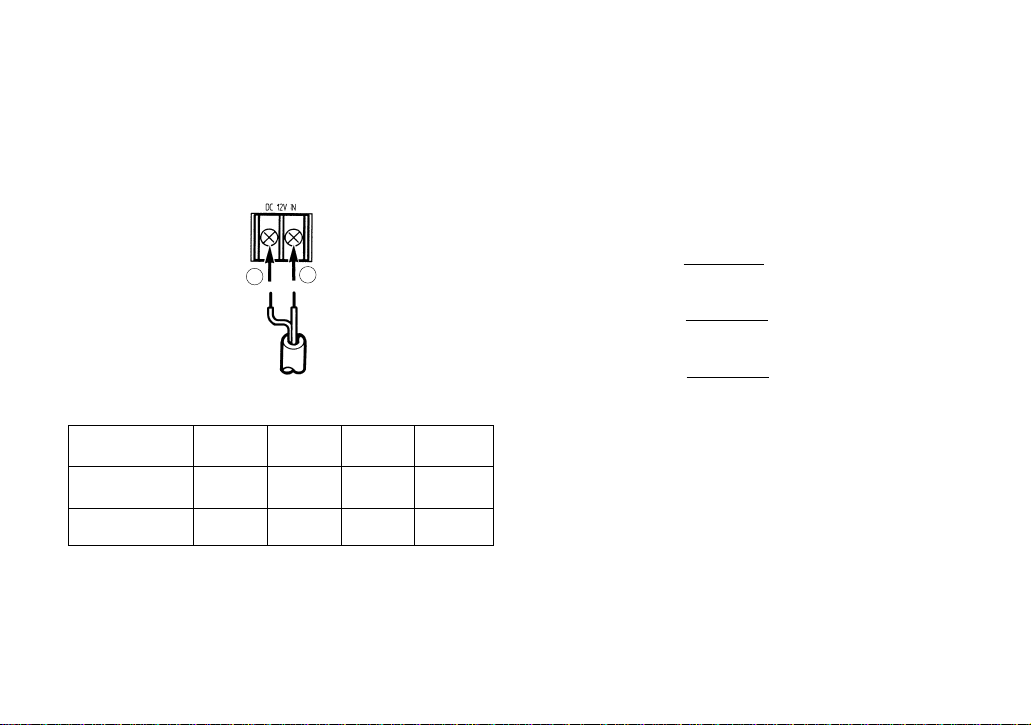
1. A power supply of 12V DC is required.
2. Connect the power cable to the 12V DC Power
Terminal on the rear panel of the camera.
Copper wire #24 #22 #20 #18
size (AWG) (0.22mm2) (0.33mm2) (0.52mm2) (0.83mm2)
Resistance 0.257 0.165 0.099 0.059
ohms/ft
Resistance 0.078 0.050 0.030 0.018
ohms/m
Resistance of copper wire [at 20°C (68°F)]
12 VDC
(10.5 V - 16 V)
−
+
• Calculation method of maximum cable length
between camera and power supply.
10.5V DC ≤ V
A − (R x 0.42 x L) ≤ 16V DC
L : Cable length (meter)
R : Resistance of copper wire (ohms/meter)
V
A : DC output voltage of power supply unit
V
A − 12
L standard = (meter)
0.42 x R
V
A − 16
L minimum = (meter)
0.42 x R
V
A − 10.5
L maximum = (meter)
0.42 x R
-8-
Page 11
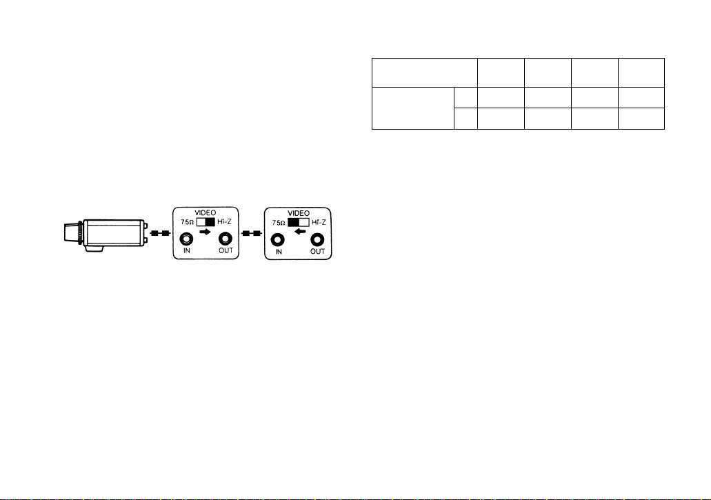
Video Cable
1. It is recommended to use a video monitor whose
resolution is at least equal to the camera's.
2. Terminate the camera output with 75-ohm resistor
at the furthest end of its cable run.
A. It is recommended to use 75-ohms coaxial
cable.
(RG-59/U, RG-6/U, RG-11/U, RG-15/U)
B. Always set the last monitor`s termination
switch to 75 ohms, and set the termination
switches of intermediate monitors to high
impedance (Hi-Z) position.
C. The maximum extensible coaxial cable length
between the camera and the monitor is shown
in the table 1. Since cable quality varies
among manufactures, verify video quality
before final installation if maximum length are
to be used.
Monitor
Monitor
-9-
Type of RG-59/U RG-6U RG-11/U RG-15/U
coaxial cable (3C-2V) (5C-2V) (7C-2V) (10C-2V)
Recommended (ft) 825 1,650 1,980 2,640
maximum
cable length (m) 250 500 600 800
Table 1
3. Wiring precautions :
• Do not bend coaxial cable into a curve whose
radius is smaller than 10 times the cables diameter.
• Never staple the cable - not even with circular staples. Mismatching will occur.
• Never crush or pinch the cable
All of these will change the impedance of the
cable and cause poor picture quality.
Page 12
Caution: Always set the Flange-back adjusting ring to
fully clockwise (C-mount side) by loosing the
screw on the ring before mounting the lens otherwise the inner glass and CCD image sensor could
be damaged by the lens.
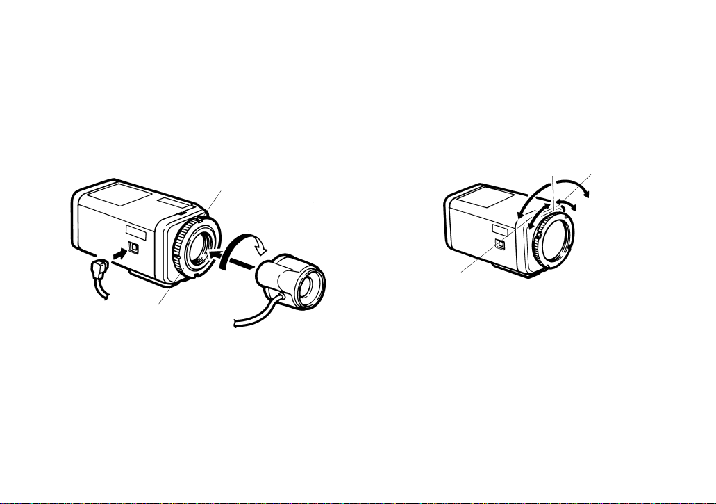
MOUNTING THE LENS
(1) Mount the lens by turning it clockwise onto the
lens mount of the camera.
(2) Connect the lens cable to the Auto Iris Lens
Connector on the camera when an auto iris lens is
used.
-10-
1
2
Screw
Flange-back
Adjusting Ring
FLANGE-BACK FOCAL LENGTH ADJUSTMENT
The following adjustment should be made by qualified
service personnel or system installers.
When the flange-back focal length should be changed,
the following adjustment is necessary.
Focus adjust for
C-mount lens
Focus adjust for
CS-mount lens
Page 13

-11-
PREVENTION OF BLOOMING AND SMEAR
When the camera is aimed towards spotlights or other
bright lights or light reflecting objects, smear or blooming may appear. Therefore the camera should be operated carefully in the vicinity of extremely bright objects
to avoid smear or blooming.
If the camera is aimed at the sun or very bright light,
such as laser beam, for a long period of time, the CCD
image sensor may be burned in and blemishes (white
or black dots) appears on the picture.
Bright object
Smear
Page 14

SPECIFICATIONS
Pick-up Device : 752(H) x 582(V) pixels, 1/2” Interline Transfer CCD
Scanning System : 2 : 1 Interlace
Scanning : 625 Lines / 50 Fields / 25 Frames
Horizontal : 15,625 kHz
Vertical : 50 Hz
Horizontal Resolution : 480 lines
Video Output : 1.0 Vp-p PAL composite, 75 ohms/BNC connector
Signal to Noise Ratio : 50 dB (AGC OFF)
Electronic Light Control : Equivalent to continuous variable shutter speed between 1/50 sec. and
1/15,600 sec.
Minimum Illumination : 3 lux (0.3 footcandle) at F 1.4 (AGC ON)
White Balance : AWC / ATW selectable
Back-Light Compensation : Selectable On/Off
Sync System : Internal
Aperture : Selectable Soft/Sharp
AGC : Selectable On/Off
Ambient Operating Temperature : −10° C - +50° C (14° F - +122° F)
Power Source : 10.8 - 16 V DC, 300mA
Dimensions (excluding lens) : 67(W) X 55(H) X 123(D) mm
2-5/8”(W) X 2-3/16”(H) X 4-13/16”(D)
Weight (excluding lens) : 460g (1.0 lbs.)
Weights and dimensions indicated are approximate.
Specifications are subject to change without notice.
-12-
Page 15

-13-
Die Fabriknummer dieses Gerätes ist auf dessen Bo-denabdeckung angegeben.
Sie sollten die Fabriknummer dieses Gerätes in den da-für
vorgesehenen Raum eintragen und diese Anleitung als
Kaufsunterlage aufbewahren, um im Falle eines Diebstahls
die ldentifizierung zu erleichtern.
Modellnummer
Fabriknummer
WARNUNG: UM DIE GEFAHR VON BRAND ODER STROMSCHLAG ZU VERHÜTEN, DIESES GERÄT WEDER
REGEN NOCH FEUCHTIGKEIT AUSSETZEN.
Das Blitzzeichen mit Pfeil im gleichseitigen Dreieck soll den Benutzer auf das
Vorhandensein von nichtisolierter "gefährlicher Spannung" innerhalb des Gehäuses hinweisen, die so groß sein kann,
daß sie Gefahr eines elektrischen Schlags
darstellt.
Das Ausrufezeichen im gleichseitigen
Dreieck soll den Benutzer auf wichtige
Bedienungs und Wartungsanweisungen in
den Unterlagen hinweisen, die dem Gerät
beiliegen.
Bescheinigung des Herstellers/Importeurs
Hiermit wird bescheinigt, daß der/die/das
Digital-Farbkamera GP-KR222E
(Gerät, Typ, Bezeichnung)
in Übereinstimmung mit den Bestimmungen der
VFG 1046/1984
(Amtsblattverfügung)
funkentstört ist.
Dieses Gerät entspricht als Einzelgerät den Entstörauflagen der
Amtsblatt-Vfg. 1046/1984 bzw. VDE 0871/6.78, Grenzwerklasse
B.
Beim Betried innerhalb von Anlagen sind die einschlägigen
Funkentstörbestimmungen einzuhalten.
Der Deutschen Bundespost wurde das Inverkehrbringen dieses
Gerätes angezeigt und die Berechtigung zur Überprüfung der Serie
auf Einhaltung der Bestimmungen eingeräumt.
Panasonic Deutschland GmbH
Name des Herstellers/Importeurs
Dieses Modell entspricht der EG-Vorschrift (für Funkstörungsschutz) 87/308/EG.
WARNUNG:
WEDER DECKEL NOCH RÜCKPLATTE
ABNEHMEN, UM DIE GEFAHR EINES ELEKTRISCHEN SCHLAGS ZU VERMEIDEN, DAS
GERÄT ENTHÄLT KEINE BAUTEILE, DIE VOM
KUNDEN GEWARTET WERDEN KÖNNEN.
CAUTION
RISK OF ELECTRIC SHOCK
DO NOT OPEN
DEUTSCHE AUSGABE
(GERMAN VERSION)
DEUTSCH
Page 16

-14-
INHALT
VORWORT .................................................................................................................................................................... 15
MERKMALE .................................................................................................................................................................. 15
VORSICHTSMASSREGELN .......................................................................................................................................... 16
WICHTIGE BEDIENUNGSELEMENTE UND IHRE FUNKTIONEN ................................................................................17
ANSCHLÜSSE .............................................................................................................................................................. 21
ANBRINGEN DER OBJEKTIVS ..................................................................................................................................... 23
RÜCKFLANSCHBRENNWEITENEINSTELLUNG .......................................................................................................... 24
VERMEIDUNG VON ÜBERSTRAHLEN UND LEUCHTFAHNEN ...................................................................................24
TECHNISCHE DATEN .................................................................................................................................................. 25
Die in dieser Bedienungsanleitung aufgeführten Modellnum-mern weisen keinen Anhang auf.
Page 17

-15-
VORWORT
Die Digital-Farbkamera der GP-KR222 von Panasonic
stellen hohe Bildqualität und hohe Auf-lösung sicher,
da ein 1/2-Zoll Zwischenzeilen-CCD-Bildsensor mit 752
horizontalen Bildelementen und DigitalSignalverarbeitungs-LSIs verwendet werden.
Hohe Empfindlichkeit wird durch Verwendung von "onchip" Mikro-Linsen für jeden Bildpunkt gewährleistet.
Zusätzlich wird die Empfindlichkeit durch asphärische
Objektive hoher Lichtstärke weiter verbessert. Durch
die Verwendung neuentwickelter Digital-LSIs wird ein
ausgezeichnetes Preis/Leistungs-Verhältnis sichergestellt.
MERKMALE
1. Mit Funktionen für automatische Lichtregelung
(ALC)/elektronische Lichtregelung (ELC) ausgestattet.
2. Hintergrundbeleuchtungskompensation steht zur
Verfügung.
3. Funktionen für automatischen/manuellen Weißabgleich können benutzt werden.
4. Zwischen weicher/scharfer Blendenôffnung wählbar.
5. Rauschspannungsabstand 50 dB
6. Mindestbeleuchtung 3 Lux mit F1,4 Objektiv
7. Mindestbeleuchtung 0,9 Lux bei Verwendung eines
asphärischen Objektivs hoher Lichtstärke (F0,75)
von Panasonic
8. 480 Zeilen horizontale Auflösung
9. Hohe Bildqualität:
(a) 2H-Typ Vertikalbetoner für bessere Bildschärfe
(b) Chromasignal-Durchschnittswert-Schaltkreis für
besseren Farb-Fremdspannungsabstand
(c) Minimaler Umfalteffekt bei feinen Objekten
(d) Größerer Dynamikbereich durch die Benutzung
eines Knieschaltunngs-Rauschspannungsab-
stands.
(e) Starklicht-Blendenkorrektur für verbesserte Ein-
zelheiten bei hellen Objekten
10. Möglichkeit von Innenaufnahmen mit Objektiv mit
fester Blende durch die Verwendung der elektronischen Lichtregelungsfunktion (ELC)
11. Hintergrundbeleuchtungskompensation für die Verwendung bei ungewöhnlichen Beleuchtungsbedingungen
Page 18

-16-
4. Die Kamera niemals auf die Sonne richten.
Ganz gleich, ob die Kamera in Betrieb ist oder
nicht, sollte diese niemals auf die Sonne oder ein
extrem helles Objekt, wie z.B. einen Laserstahl,
gerichtet werden, weil, dadurch der CCDBildsensor beschädigt oder das Bild verschmiert
werden könnte.
5. Die Kamera nicht außerhalb ihrer vorgeschriebenen Temperatur-, Luftfeuchtigkeitsoder Stromversorgungsbereiche betreiben.
(a) Für Verwendung in Innenräumen vorgesehen.
(b) Die Umgebungstemperatur darf den Bereich
von −108°C bis +50°C nicht überschreiten.
(c) Die Kamera nicht verwenden, wenn die
Luftfeuchtigkeit 90% übersteigt.
(d) Die Eingangsstromversorgung beträgt 12V
Gleichstrom, 300 mA.
VORSICHTSMASSREGELN
1. Niemals die Kamera zerlegen.
Um elektrische Schläge zu vermeiden, niemals
Schrauben oder Abdeckungen entfernen. Im Inneren der Kamera befinden sich keine vom Anwender wartbare Teile.
Wartungsarbeiten sollten nur von qualifizierten
Wartungstechnikern ausgeführt werden.
2. Die Kamera vorsichtig behandeln.
Die Kamera muß immer sorgfältig behandelt werden. Stöße und Erschütterungen vermeiden. Bei
falscher Handhabung oder Lagerung kann die
Kamera beschädigt werden.
3. Regen und Feuchtigkeit vermeiden; die Kamera
nicht an nassen Orten verwenden.
Falls die Kamera naß wird, sind sofortige Maßnahmen erforderlich. Die Stromversorgung ausschalten, und die Kamera von einem qualifizierten
Wartungstechniker warten lassen. Feuchtigkeit
kann die Kamera beschädigen und zu elektrischen Schlägen führen.
Page 19

-17-
L
VIDEO OUT
OFF
ELC
SOFT
OFF
OFF
AGC ON
ALC
SHARP
BLC ON
ATW ON
H
DC 12V IN
GP-
KR222
VIDEO
LEVEL
POWER
S VIDEO OUT
R B
(AWC)
!1 !2 !3 !4
!0
q
we
rt
u
i
o
y
WICHTIGE BEDIENUNGSELEMENTE UND IHRE FUNKTIONEN
Page 20

-18-
1. Kamera-Befestigungsbohrung
Diese Gewindebohrung (1/4” - 20) wird für die
Montage der Kamera auf einer Einbaukonsole
oder einem Stativ verwendet.
2. Rückflansch-Einstellring
Wird für die Einstellung der Rückflansch-Brennweite oder der Bildschärfe verwendet, indem
dieser Ring für Objektive mit C-Fassung im
Uhrzeigersinn oder für Objektive mit CS-Fassung
gegen den Uhrzeigersinn gedreht wird.
VORSICHT:
1. Diesen Ring immer bis zum Anschlag im
Uhrzeigersinn drehen, bevor das Objektiv
angebracht wird, um eine Beschädigung des
inneren Glases oder des CCD-Bildsensors zu
vermeiden.
2. Diesen Ring nicht zu weit gegen den
Uhrzeigersinn drehen, wenn ein Objektiv mit
C-Fassung angebracht ist, da sonst der
innere CCD-Bildsensor beschädigt werden
kann.
3. Objektiv (Option)
4. 12V-Gleichstrom-Eingangsklemme (DC 12V IN)
Diese Klemme ist zum Anschließen einer 12VGleichstromquelle (10,8V - 16V) vorgesehen.
5. Ein/Aus-Schalter für automatische
Verstärkungsregelung (AGC ON/OFF)
Dieser Schalter wird verwendet, um den
Verstärkungsgrad des Videoverstärkers wie folgt
zu wählen :
ON: Wenn die Objektivblende beim Aufnehmen
bei schlechten Lichtverhältnissen ganz
geöffnet wird, läßt sich durch die automatische Erhöhung des Verstärkungsgrads ein
klares Bild erzielen.
OFF: Bei schwacher Beleuchtung läßt sich ein
natürliches und störungsarmes Bild erzielen.
6. Wahlschalter für elektronische Lichtregelung/
automatische Lichtregelung (ELC / ALC)
Dieser Schalter wird verwendet, um das Objektiv
wie folgt zu wählen :
ALC: Diese Stellung wählen, wenn ein Objektiv mit
automatischer Blendenregelung verwendet
wird.
ELC: Diese Stellung wählen, wenn ein Objektiv mit
Festblende oder manueller Blendenregelung
verwendet wird.
7. Detailpegel-Wahlschalter (SOFT/SHARP)
Der Detail-/Blendenöffnungspegel kann mit Hilfe
dieses Schalters gewählt werden. diesen Schalter
auf die gewünschte Stellung einstellen, während
dabei das Bild auf dem Monitor-Bildschirm
beobachtet wird.
Page 21

-19-
Zur Beachtung: Die Blendenöffnung wird in der
Stellung "SOFT" nicht beeinflußt.
8. HintergrundbeleuchtungskompensationsEin/Aus-Schalter (BLC ON/OFF)
Wenn eine Hintergrundbeleuchtung das Bild
beeinträchtigt, diesen Schalter auf "ON" einstellen,
um ein klares Bild erzielen zu können.
9. Ein/Aus-Schalter für Weißabgleich mit
automatischer Abtastung (ATW, ON/OFF(AWC))
Die Einstellung des Weißabgleichs kann wie folgt
gewählt werden :
ON: Die Einstellung des Weißabgleichs erfolgt
automatisch und fortlaufend durch Erkennen
der Charakteristik/Farbtemperatur der Lichtquelle und Regeln des Verstärkungsgrads der
Rot- und blausignale, selbst wenn sich die
Charakteristik/Farbtemperatur ändert.
Zur Beachtung: Die Einstellung des Weißabgle-
ichs wird durch den Einstellpegel des Reglers
für Weißableich mit automatischer Abtastung
(11) beeinflußt. (ein bläuliches Weiß ergibt
sich, wenn der erwähnte Regler auf die Seite
B eingestellt worden ist.)
OFF: Der Weißableich wird automatisch eingestellt
und festgehalten, wenn von weißableich mit
automatischer Abtastung auf automatischen
Weißabgleich umeschaltet wird. Wenn sich
die Charakterisitik/Farbtemperatur der Lichtquelle ändert, diesen Schalter auf die Stellung
"ATW ON", dann wieder auf "OFF" einstellen.
Zur Beachtung: Die Einstellung des Weißabgle-
ichs wird durch den Einstellpegel des Reglers
für Weißabgleich mit automatischer Abtastung
(11) beeinflußt. (Ein bläuliches Weiß ergibt
sich, wenn der erwähnte Regler auf die seite
b eingestellt worden ist.)
10. Einschaltanzeige (POWER)
11. Regler für Weißableich mit automatischer
Abtastung (ATW ON, R/B)
Tieser Regler regelt den Pegel des Rot- und BlauFarbabgleichs, selbst wenn der Ein/Aus-Schalter
für Weißabgleich mit automatischer Abtastung (9)
beliebig eingestellt wird. Dieser Regler ist auf die
mittlere Position voreingestellt worden, die
gewöhnlich für eine genaue Farbwiedergabe
sorgt.
Page 22

-20-
12. Videopegelregler (VIDEO LEVEL, L/H)
Dieser Regler regelt bei Einstellung des
Wahlschalters für elektronische Lichtregelung/automatische Lichtregelung (6) auf die Position
"ALC" den Pegel der Blendenautomatik bzw. bei
Einstellung des Wahlschalters (6) auf die Position
"ELC" den Pegel der elektronischen Lichtregelung.
Zur Beachtung: Dieser Regler funktioniert unter
den folgenden bedingungen nicht :
• Der Ein/Aus-Schalter für automatische
Verstärkungsregelung (AGC ON/OFF) (5) ist
bei Verwendng eines Objektivs mit
Festblende oder manueller blendenregelung
auf "OFF" eingestellt worden.
• Die automatische Verstärkungsregelung erreicht bei Einstellung des erwähnten Schalters
(5) auf "ON" den maximalen Pegel.
13.S-Videoausgangs-Steckverbinder
(S-VIDEO OUT)
Die Luminanz(Y)- und Chroma(C)-Signale für den
Monitor stehen an diesem Steckverbinder zur
Verfügung.
14. Videoausgangs-Steckverbinder (VIDEO OUT)
Ein Videosignalgemisch mit 1,0 Vss steht an
diesem Steckverbinder zur Verfügung.
Beschreibung der elektronischen Lichtregelung (ELC)/Hintergrundbeleuchtungskompensation (BLC)
1. Elektronische Lichtregelung (ELC)
In dieser Betriebsart wird ein stufenlos geregelter
elektronischer Verschluß benutzt, um die
Belichtungszeiten im CCD-Bildsensor entsprechend dem Pegel des einfallenden Lichtes
automatisch zu steuern. Bei Wahl dieser
Betriebsart kann anstelle eines Objektivs mit
automatischer Lichtregelung ein Objektiv mit
Festblende oder manueller Blendenregelung verwendet werden.
Vorsichtsmaßregeln :
1. Bei hellem Licht, wie z.B. im Freien, ein
Objektiv mit automatischer Lichtregelung verwenden, weil der Bereich der elektronischen
Lichtregelung unter diesen bedingungen nicht
groß genug ist.
2. Unter bestimmten ungewöhnlichen beleuchtungsbedingungen können die folgenden
Störungen auftreten :
• Starke Verschmierung und/oder Überstrahlen
bei Objekten, die durch Scheinwerfer oder
Tageslicht in Fensternähe hell beleuchtet
sind.
• Ein wahrnehmbares Flimmern im Bild
und/oder eine unterschiedliche Farbwiedergabe.
Page 23

-21-
−
+
ANSCHLÜSSE
1. Eine Stromversorgung von 12V Gleichstrom ist
erforderlich.
2. Das Stromversorgungskabel an die Eingangsklemme für 12V Gleichstrom (DC 12V IN) (4) an
der Rückwand der Kamera anschließen.
12 V Gs
(10,5 V - 16 V)
2. Hintergrundbeleuchtungskompensation (BLC)
EIN AUS
• Eine periodische Varianz des Farbabgleichs.
Sollten derartige Störungen auftreten, ein
Objektiv mit automatischer Lichtregelung verwenden.
Wenn sich eine starke, unerwünschte Hintergrundbeleuchtung störend auf die Deutlichkeit
wichtiger Szenenobjekte auswirkt, den Hintergrundbeleuchtungskompensations-Ein/AusSchalter (8) auf "ON" einstellen.
Vorsicht :
Einstellung dieses Schalters auf "BLC OFF" ist
empfehlenswert, wenn der Kopf für Schwenken/Neigen verwendet wird oder wenn sich
die beleuchtung eines Objekts schnell ändert,
weil die Geschwindigkeit der Objektivblende
in der Stellung "BLC ON" abnimmt.
Kupferdraht #24 #22 #20 #18
Querschnitt (0,22 mm
2
) (0,33 mm2) (0,52 mm2) (0,83 mm2)
Widerstand (AWG)
Widerstand 0,257 0,165 0,099 0,059
Ohm/Fuß
Widerstand 0,078 0,050 0,030 0,018
Ohm/m
Widerstand des Kupferdrahtes (20°C)
Page 24

-22-
Videokabel
1. Es ist empfehlenswert, einen Videomonitor zu verwenden, dessen Auflösung mindestens derjenigen
der Kamera entspricht.
2. Den Kameraausgang am äußersten Kabelende mit
einem 75-Ohm-Widerstand abschließen.
A. Es ist empfehlenswert, ein 75-Ohm-Kabel
(RG-59/U, RG-6/U, RG-11/U, RG-15/U) zu verwenden.
B. Immer den Abschlußschalter des letzten
Monitors auf 75 Ohm einstellen, und die
Abschlußschalter der dazwischenliegenden
Monitore auf HIGH (Hi-Z) stellen.
C. Die maximale Länge des Koaxialkabels zwi-
schen der Kamera und dem Monitor ist in
Tabelle 1 aufgeführt. Da die Kabelqualiät vom
Hersteller abhängt, die Bildqualität vor dem
endgültigen Einbau überprüfen, wenn die
maximale Länge verwendet wird.
OUTIN 75 
Hi-Z
VIDEO
OUTIN 75 
Hi-Z
VIDEO
Monitor
Monitor
• Berechnung der maximalen Kabellänge zwischen
Kamera und Stromversorgung.
10,5V DC ≤ V
A - (R x 0,42 x L) ≤ 16V DC
L: Kabellänge (Meter)
R: Widerstand des Kupferdrahtes (Ohm/m)
V
A: Gleichspannung der Stromversorgung
V
A − 12
L Standard = (Meter)
0,42 x R
V
A − 16
L Minimum = (Meter)
0,42 x R
V
A − 10.5
L Maximum = (Meter)
0,42 x R
Page 25

-23-
Vorsicht:
Immer den Rückflansch-Einstellring bis zum
Anschlag im Uhrzeigersinn drehen (C-Fassungsseite), indem eine Schraube an dem Ring gelöst
wird, bevor das Objektiv angebracht wird, da
anderenfalls das innere Glas und der CCD-Bildsensor durch das Objektiv beschädigt werden
können.
ANBRINGEN DER OBJEKTIVS
(1) Das Objektiv anbringen, indem dieses im
Uhrzeigersinn auf die Objektivfassung der Kamera
aufgeschraubt wird.
(2) Das Objektivkabel an den Steckverbinder für das
Objektiv mit Blendenautomatik an der Kamera
anschließen, wenn ein Objektiv mit Blendenautomatik verwendet wird.
1
2
Schraube
RückflanschEinstellring
3. Vorsichtsmaßregeln für die Verdrahtung:
• Der Biegeradius des Koaxialkabels darf den zehnfachen Kabeldurchmesser nicht unterschreiten.
• Das Kabel niemals mit Krampen befestigen, auch
nicht mit runden Krampen. Es könnte zu einer
Fehlanpassung kommen.
• Das Kabel niemals zerquetschen oder zusammendrücken.
All diese Probleme ändern die Impedanz des
Kabels und können zu einer schlechten Bildqualität führen.
Tabelle 1
Koaxialkabeltyp RG-59/U RG-6U RG-11/U RG-15/U
(3C-2V) (5C-2V) (7C-2V) (10C-2V)
Empfohlene (ft) 825 1650 1980 2640
maximale
Kabellänge (m) 250 500 600 800
Page 26

-24-
VERMEIDUNG VON ÜBERSTRAHLEN UND LEUCHTFAHNEN
Wenn die Kamera auf Scheinwerfer oder andere helle
Lichter und lichtreflektierende Objekte gerichtet ist,
kann es zu Leuchtfahnen oder zu Überstrahlen kommen. Daher sollte die Kamera in der Nähe von extrem
hellen Objekten sorgfältig bedient werden, um derartige Störungen zu vermeiden.
Wird die Kamera für längere Zeit auf die Sonne oder
ein sehr helles Licht (wie z.B. Laser-Strahl) gerichtet,
dann kann es zu einem Einbrennen auf dem CCDBildsensor kommen, so daß weiße oder schwarze
Punkte in dem Bild erscheinen.
Helles Objekt
Leuchtfahne
RÜCKFLANSCHBRENNWEITENEINSTELLUNG
Die folgende Einstellung sollte von qualifiziertem
Kundendienstpersonal oder Systemmonteuren vorgenommen werden.
Wenn die Rückflansch-Brennweite geändert werden
muß, ist die folgende Einstellung erforderlich.
Scharfeinstellung
für Objektiv mit
C-Fassung
Scharfeinstellung
für Objektiv mit
CS-Fassung
Page 27

-25-
TECHNISCHE DATEN
Aufnahmeelement: 752(H) x 582(V) Pixels, CCD mit 1/2-Zoll-Zwischenzeilenübertragung
Abtastsystem: 2:1 Zeilensprung
Abtastung: 625 Zeilen/50 Halbbilder/25 Vollbilder
Horizontal: 15,625 kHz
Vertikal: 50 Hz
Horizontale Auflösung: 480 Zeilen
VideoAusgang: 1,0 Vs-s PAL Komposit, 75 Ohm/BNC-Stecker
Fremdspannungsabstand: 50 dB (AGC OFF)
Elektronische Lichtsteuerung: Gleichwertig zu variabler Verschlußzeit zwischen 1/50 sek.
und 1/15.600 sek.
Mindestbeleuchtung: 3 Lux bei Blende 1,4 (AGC ON)
Weißabgleich: AWC/ATW wählbar
Hintergrundbeleuchtungskompensation: EIN/AUS wählbar
Synch.-System: Internen
Blendenöffnung: Zwischen Weich/Scharf wählbar
Automatische Verstärkungsregelung: Zwischen Ein/Aus wählbar
Zul. Umgebungstemperatur: −10° C - +50° C
Stromversorgung: 10,8 - 16 V Gleichstrom, 300mA
Abmessungen (ohne Objektiv): 67(B) x 55(H) x 123(T) mm
Gewicht (ohne Objektiv): 460 g
Abmessungen und Gewicht sind ungefähre Werte.
Änderungen der technischen Daten ohne Vorankündigung vorbehalten.
Page 28

-26-
AVERTISSEMENT: NE JAMAIS EXPOSER CET APPAREIL À LA PLUIE NI LE LAISSER DANS UN LIEU HUMIDE
SOUS PEINE DE CRÉER UN AMORÇAGE ÉLECTRIQUE OU UNE ÉLECTROCUTION.
L'éclair à extrémité fléchée placé dans un
triangle équilatéral est destiné à attirer l'attention de l'utilisateur sur la présence
d'une "tension potentiellement dangereuse" et non isolée se trouvant dans
les limites du coffret de l'appareil dont la
puissance est suffisante pour constituer un
risque important d'électrocution.
Le numéro de série de l'appareil se trouve sur la plaque de
fond.
Nous vous conseillons de relever le numéro de série de
votre appareil dans l'espace réservé ci-dessous et de conserver précieusement votre notice d'instructions en tant que
justificatif d'achat aux fins d'identification en cas de vol.
No. de modèle
No. de série
Cet appareil est conforme aux prescriptions de la directive
87/308/C.E.E. (concernant les interférences radio).
La Société PANASONIC-FRANCE, importateur du matériel
MATSUSHITA-JAPON déclare que cet appareil est conforme aux prescriptions de la directive 87/308/C.C.E. modifiée par la directive 82/499/CEE.
ATTENTION:
POUR ÉVITER TOUT RISQUE D'ÉLECTROCUTION,
LE COUVERCLE (OU LE PANNEAU ARRIÈRE) NE
DOIT JAMAIS ÊTRE DÉMONTÉ. AUCUNE PIÈCE
DESTINÉE À L'UTILISATEUR SE TROUVE À L'INTÉRIEUR DE L'APPAREIL. CONFIER LES RÉGLAGES ET LES RÉPARATIONS À UN DÉPANNEUR
PROFESSIONNEL.
CAUTION
RISK OF ELECTRIC SHOCK
DO NOT OPEN
VERSION FRANÇAISE
(FRENCH VERSION)
Le point d'exclamation placé dans un triangle équilatéral sert à attirer l'attention
de l'utilisateur sur des instructions de
fonctionnement et d'entretien (de dépannage) à caractère important dans la
brochure qui accompagne l'appareil.
Page 29

-27-
SOMMAIRE
PRÉFACE ...................................................................................................................................................................... 28
CARACTÉRISTIQUES DOMINANTES ........................................................................................................................... 28
MESURES DE PRÉCAUTION ........................................................................................................................................ 29
COMMANDES PRINCIPALES ET FONCTIONS ............................................................................................................ 30
RACCORDEMENTS ...................................................................................................................................................... 34
INSTALLATION DEL'OBJECTIF .................................................................................................................................... 36
RÉGLAGE DE LONGUEUR FOCALE DE FOYER ARRIÈRE ......................................................................................... 37
MESURE PRÉVENTIVE CONTRE L'HYPERLUMINOSITÉ ET LE TRÎNAGE .................................................................. 37
FICHE TECHNIQUE ...................................................................................................................................................... 38
Les numéros de modèle qui sont mentionnés dans les instructions d'utilisation n'ont aucune suffixe indiqué.
FRANÇAIS
Page 30

-28-
PRÉFACE
La caméra vidéo de surveillance couleur et numériques GP-KR222 Panasonic introduit une nouvelle
norme en termes de haute qualité d'image et de
résolution supérieure grâce à l'adoption d'un nouveau
type d'analyseur d'image à transfert de charges de
lignes de 1/2 pouce de 752 pixels horizontaux
(éléments d'image), mais aussi avec l'emploi de circuits à intégration à grande échelle de traitement de
signaux numériques.
La haute sensibilité est assurée par l'utilisation de
micro-lentilles sur puces pour chaque élément d'image. En outre, l'adjonction d'objectifs à lentilles asphériques à haute luminosité renforce la sensibilité
générale. Un rapport hautes performances-qualité-prix
tout à fait favorable est ainsi obtenu grâce à un usage
intensif de nouveaux types de circuits numériques à
intégration à grande échelle.
CARACTÉRISTIQUES DOMINANTES
1. Fonctions de contrôle automatique de lumière
(ALC)/contrôle électronique de lumière (ELC)
incorporées.
2. Compensation d'éclairage en contre-jour disponible.
3. Pourvue des fonctions de contrôle automatique/
manuel de balance des blancs.
4. Sélection d'ouverture enveloppée/détaillée
5. Rapport signal-sur-bruit de 50 dB
6. Éclairement minimum de 3 lux avec des objectifs
f/1,4 asphériques à haute luminosité Panasonic.
7. Éclairement minimum de 0,9 lux avec des objectifs
asphériques à haute luminosité Panasonic (f/0,75).
8. Résolution horizontale de 480 lignes.
9. Images à huate définition:
(a) Optimiseur vertical numérique de 2H renfor-
çant la netteté des images
(b) Circuit de pondération de chrominance favori-
sant un rapport signal-sur-bruit couleur supérieur
(c) Élimination minimale des sujets les plus in-
fimes
(d) Étalement de la gamme dynamique grâce à
l'usage d'un circuit de contrôle rapport signalsur-bruit à rotule (3).
(e) Correction d'ouverture sous éclairage puis-
sant en faveur d'une meilleure définition des
images de sujets brillants
10. Possibilité d'enregistrement de scènes en intérieur
avec un objectif à focale fixe et en utilisant la fonction de contrôle électronique de lumière (ELC).
11. Compensation d'éclairage en contre-jour permettant de filmer dans des conditions d'éclairage
inhabituelles.
Page 31

-29-
4. Ne jamais diriger la caméra vidéo de
surveillance directement vers le soleil.
Que la caméra soit mise en service ou non, il ne
faut jamais la diriger directement vers le soleil ni
en direction de toute autre source lumineuse puissante tel qu'un rayon laser lumineux, etc., sous
peine d'endommager l'analyseur d'image à
système à transfert de charges ou de provoquer
un traînage.
5. La caméra vidéo de surveillance ne doit pas
être mise en service au-delà de ses limites de
température, d'humidité et de puissance
d'alimentation.
(a) Conçue pour être utilisée
(b) Les limites de température ne doivent pas
être dépassées −10° C à +50° C.
(c) Éviter de mettre la caméra vidéo de surveil-
lance dans un milieu où le taux d'humidité est
supérieur à 90%.
(d) La source d'alimentation doit être de 12V de
courant continu et 300 mA.
MESURES DE PRÉCAUTION
1. Ne jamais essayer de démonter cette caméra
vidéo de surveillance.
Ne jamais retirer les vis de fixation ni les éléments
du coffret de la caméra vidéo de surveillance sous
peine de risque d'électrocution. Aucun composant
destiné à l'utilisation du propriétaire de l'appareil
n'a été placé à l'intérieur.
Confier les réglages et le dépannage à un technicien professionnel.
2. Manipuler la caméra vidéo de surveillance avec
délicatesse.
Ne jamais manipuler brutalement cette caméra
vidéo de surveillance. Lui éviter tout choc et secousses. Cette caméra vidéo de surveillance
risque d'être endommagée à la suite d'une manipulation brutale ou d'un rangement inapproprié.
3. Ne jamais exposer la caméra vidéo de surveillance à la pluie ni la soumettre à l'humidité et
éviter de la placer dans des lieux humides.
Prendre immédiatement les mesures qui s'imposent si la caméra vidéo de surveillance a été
mouillée. Couper tout de suite l'alimentation et
demander à un technicien professionnel de la
vérifier. Non seulement l'humidité risque d'endommager la caméra vidéo de surveillance, mais ceci
peut également favoriser une électrocution dans
les pires cas.
Page 32

-30-
L
VIDEO OUT
OFF
ELC
SOFT
OFF
OFF
AGC ON
ALC
SHARP
BLC ON
ATW ON
H
DC 12V IN
GP-
KR222
VIDEO
LEVEL
POWER
S VIDEO OUT
R B
(AWC)
!1 !2 !3 !4
!0
q
we
rt
u
i
o
y
COMMANDES PRINCIPALES ET FONCTIONS
Page 33

-31-
1. Embase filetée de montage de caméra vidéo de
surveillance
Cette embase filetée (de 1/4 de pouce - 20) permet d'installer la caméra vidéo de surveillance sur
une potence ou un trépied.
2. Bague de réglage de foyer arrière
Cette bague permet d'effectuer un réglage de
foyer arrière ou de mise au point de l'image par
simple rotation dans le sens horaire dans le cas
d'un objectif à monture de type C ou dans le sens
horaire inverse dans le cas d'un objectif à monture
de type CS.
Attention:
1. Cette bague doit toujours être tournée au
maximum dans le sens horaire avant que soit
monté un objectif sur la caméra vidéo de surveillance afin de pas endommager la surface
en verre de l'analyseur d'image à dispositif de
transfert de charges.
2. Ne jamais tourner excessivement cette bague
dans le sens horaire inverse quand un objectif
à monture C est installé sur la caméra vidéo
de surveillance car ceci aurait pour effet d'endommager la surface en verre de l'analyseur
d'image à dispositif de transfert de charges.
3. Objectif (Option)
4. Bornes d'entrée 12V de courant continu
(DC 12V IN)
Cette borne de raccordemnt permet de recevoir
du courant d'alimentation continu de 12V (10,8 16V).
5. Commutateur de contrôle automatique de gain
(AGC ON/OFF)
Ce commutateur est utilisé pour sélectionner le
gain de l'amplificateur vidéo de la façon suivante :
ON: Lorsque le diaphragme de l'objectif est
complètement ouvert sous de faibles conditions d'éclairage, une image claire est
obtenue grâce à l'accroissement automatique
du gain.
OFF: Une image aux couleurs naturelles et à
faible bruit est obtenue sous de faibles conditions d'éclairage.
6. Sélecteur de contrôle automatique de
lumière/contrôle électronique de lumière (ELC /
ALC)
Ce sélecteur est utilisé pour choisir un objectif de
la façon suivante.
ALC: Choisir cette position quand un objectif à
diaphragme automatique est utilisé.
ELC: Choisir cette position quand un objectif à
focale fixe ou à diaphragme à réglae manuel
est utilisé.
7. Sélecteur de niveau de détail (SOFT/SHARP)
Le niveau de détail/d'ouverture peut être choisi
avec ce sélecteur. Le placer sur la position voulue
tout en observant les imaes sur l'écran du moniteur vidéo.
Remarque: L'ouverture ou conpée avec la posi-
tion SOFT.
Page 34

-32-
8. Commutateur marche/arrêt de compensation
de contre-jour (BLC ON/OFF)
Lorsque la source d'éclairage en contre-jour
affecte la qualité de l'image, ce commutateur doit
être placé en position "ON" afin de pouvoir obtenir
des images de meilleure qualité.
9. Interrupteur marche-arrêt de commande de
balance des blancs par analyse automatique
(ATW, ON/OFF(AWC))
Le calage de balance des blancs peut être
sélectionné de la façon suivante :
ON: La balance des blancs est calée automa-
tiquement et en permanence par détection
des caractéristiques/température de couleur
de la source d'éclairage analysée au traverse
de l'objectif, ce qui permet de contrôler le
gain du signal du rouge et du signal du bleu
quand bien même les
caractéristiques/température de couleur de la
source d'éclairage varieraient.
Remarque: Le calage de balance des blancs est
mis en vigueur par le niveau calé de la commande ATW (11). (Le blanc bleuâtre est
obtenu quand la commande ATW a été
placée en position B.
OFF: La balance des blancs est automatiquement
calée et fixée par les conditions suivant le
positionnment AWC à ATW. Lorsque les caractéristiques/température de couleur de la
source d'éclairae analysée varient, placer le
sélecteur en position ATW ON puis le ramener
sur OFF.
Remarque: Le calage de balance des blancs est
mis en vigueur par le niveau calé de la commande ATW (11). (Le blanc bleuâtre est
obtenu quand la commande ATW a été
placée en position B.
10. Témoin d'alimentation (POWER)
11. Commande ATW (ATW ON, R/B)
Cette commande permet d'ajuster le niveau de la
balance du rouge et du bleu quand l'interrupteur
marche-arrêt de commande de balance des
blancs par analyse automatique (9) est placé sur
n'importe quelle position. Il est préréglé en position centrale, positionnement qui permet d'obtenir
normalement une excellente reproduction des
couleurs.
12. Commande de niveau vidéo
(VIDEO LEVEL, L/H)
Cette command permet d'ajuster le niveau de
commande du diaphragme automatique quand le
sélecteur ELC/ALC (6) est placé en position ALC
ou le niveau de la commande de calage électronique de lumière quand le sélecteur (6) est placé
en position ELC.
Remarque: Cette commande est inopérante dans
les conditions suivantes.
• Lorsque le sélecteur AGC ON/OFF se trouve
en position OFF et qu'un objectif à réglae
manuel ou à focale fixe est qtilisé.
Page 35

-33-
• Le gain du contrôle automatique de gain
parvient au niveau maximum quand la commande de contrôle automatique de gain (AGC
ON/OFF) (5) se trouve en position ON.
13.Connecteur de sortie S-vidéo (S-VIDEO OUT)
Les signaux de luminance (Y) et de chorminance
destinés au moniteur vidéo sont présents à ce
connecteur.
14. Connecteur de sortie vidéo (VIDEO OUT)
Un signal vidéo composite de 1,0 Vcc/75 ohms est
présent à ce connecteur.
Description du contrôle électronique de lumière (ELC)/de la compensation de contre-jour (BLC)
1. Contrôle électronique de lumière (ELC)
Avec ce mode, un obturateur électronique variable
continu est utilisé pour assurer le contrôle automatique de l'exposition dans l'analyseur d'image à
dispositif de transfert de charges en fonction du
niveau de la lumière d'arrivée. Quand ce mode est
choisi, un objectif à diaphragme fixe ou manuel
peut être utilisé à la place d'un objectif de type
ALC.
Mesures de précautions :
1. Quand les conditions d'éclairage sont bonnes
telles que la lumière extérieure, utiliser un
objectif de type ALC parce que les limites de
contrôle en mode ELC ne sont pas suffisantes
pour couvrir ces conditions d'éclairage.
2. Sous certains conditions d'éclairage, l'un des
phénomènes suivant risque de se produire
auquel cas un objectif de type ALC doit être
utilisé.
• Important traînage et/ou hyperluminosité des
sujets fortement lumineux tels que des projecteurs d'éclairage ou des fenêtres.
• Un scintillement évident des images et/ou des
variations de rendu chromatique.
• Variation périodique de balance des blancs
Se servir d'un objectif de type ALC si l'un des
phénomènes indiqués se manifeste.
Page 36

-34-
−
+
RACCORDEMENTS
1. Utiliser une source d’alimentation de 12V c.c.
2. Raccorder le cordon d’alimentation à la borne
d’entrée de 12V c.c. à l’arrière de la caméra.
12 V c.c.
(10,5 V - 16 V)
Calibre de fil de
cuivre (calibrage #24 #22 #20 #18
américain (0,22mm
2
) (0,33mm2) (0,52mm2) (0,83mm2)
normalisé) (AWG)
Résistance 0,257 0,165 0,099 0,059
ohms/ft
Résistance 0,078 0,050 0,030 0,018
ohms/m
Résistance du fil de cuivre (à 20˚C)
2. Compensation de contre-jour (BLC)
En fonction Hors service
Lorsqu'une puissante et indésirable source
d'éclairage en contre-jour affecte réellement la
définition de sujets d'observation placés au centre
de l'image, placer ce commutateur en position
"ON".
Mesures de précaution :
Il est vivement conseillé de de placer le commutateur en position "BLC OFF" quand une
tourelle télécommandée de balayage
panoramique/vertical est utilisée ou lorsqu'un
sujet exposé à de rapides changements
d'éclairement doit être observé parce que la
vitesse de réaction du diaphragme de l'objectif est plus lente en position "BLC ON".
Page 37

-35-
Câble vidéo
1. Il est recommandé d’utiliser un moniteur vidéo
dont la définition est au moins égale à celle de la
caméra.
2. Terminer la sortie de la caméra par une résistance
de 75 ohms à l’extrémité la plus éloignée du
câble.
A. Il est conseillé d'utiliser un câble coaxial de
75 ohms. (RG-59/U, RG-6/U, RG-11/U, RG15/U)
B. Régler l’interrupteur de terminaison du dernier
moniteur à 75 ohms et mettre les interrupteurs
de terminaison des moniteurs intermédiaires
en position HIGH.
C. La longueur maximale extensible du câble
coaxial entre la caméra et le moniteur est
indiquée dans le tableau 1. Étant donné que
la qualité des câbles varie d’un fabricant à
l’autre, il est préférable de vérifier la netteté
de l’image avant d’effectuer l’installation,
surtout si l’on utilise les longueurs maximales.
Moniteur vidéo
Moniteur vidéo
• Mode de calcul de la longueur maximale du câble
entre la caméra et la source d’alimentation.
10,5V de courant continu ≤ V
A − (R x 0,42 x L)
≤ 16V de courant continu
L: Longueur du câble (en mètres)
R: Résistance du fil en cuivre (ohms/mètre)
V
A: Tension de sortie c.c. du bloc d’alimentation
V
A − 12
L standard = (mètres)
0,42 x R
V
A − 16
L minimale = (mètres)
0,42 x R
V
A − 10,5
L maximale = (mètres)
0,42 x R
Page 38

-36-
Attention: La bague de réglage de foyer arrière doit
toujours être tournée au maximum dans le sens
horaire (côté monture C) en desserrant une vis de
fixation de la bague avant que soit monté l'objectif
sur la caméra vidéo de surveillance sinon la surface en verre de l'analyseur d'image à dispositif
de transfert de charges risque d'être endommagée par l'objectif.
INSTALLATION DE L'OBJECTIF
(1) Monter l'objectif en le tournant dans le sens des
aiguilles d'une montre sur la monture d'objectif de
la caméra vidéo de surveillance.
(2) Raccorder le câble de raccordement d'objectif au
connecteur d'objectif à diaphragme automatique
de la caméra vidéo de surveillance utilisée.
1
2
Vis de fixation
Bague de réglage de
focalisation arrière
3. Précautions à suivre pour le câblage:
• Ne pas plier le câble coaxial suivant une courbe
dont le rayon est inférieur à 10 fois le diamètre.
• Ne jamais agrafer le câble, même pas avec des
agrafes rondes, afin d’éviter les défauts d’accord.
• Ne pas écraser ou pincer le câble.
Si ces précautions ne sont pas observées,
l’impédance du câble risque d’être altérée et la
qualité de l’image réduite.
Tableau 1
Type de RG-59/U RG-6U RG-11/U RG-15/U
câble coaxial (3C-2V) (5C-2V) (7C-2V) (10C-2V)
Longueur
(ft) 825 1 650 1 980 2 640
maximum de câble
recommandée
(m) 250 500 600 800
Page 39

-37-
RÉGLAGE DE LONGUEUR FOCALE DE FOYER ARRIÈRE
Le réglage suivant doit être réalisé par un technicien
qualifié ou par les installateurs du système.
When the flange-back focal length should be changed,
the following adjustment is necessary.
Sujet lumineux
Traînage d'image
MESURE PRÉVENTIVE CONTRE L'HYPERLUMINOSITÉ ET LE TRÎNAGE
Lorsque la caméra vidéo de surveillance est dirigée
vers des spots d'éclairage ou vers toute source de
lumière intense ou des objets réfléchissants la lumière,
une hyperluminosité ou un traînage risquent de se produire. C'est la raison pour laquelle la caméra vidéo de
surveillance doit être mise en fonction avec circonspection en présence d'objets très lumineux pour
éviter qu'une hyperluminosité ou un traînage d'image
se produisent.
Si la caméra vidéo de surveillance est dirigée vers le
soleil ou vers une source très lumineuse tel qu'un faisceau laser pendant un long moment, ceci risque d'endommager définitivement l'analyseur d'image à dispositif de transfert de charges ou endommagé (apparition de points blancs ou noirs) sur l'image.
Réglage de
mise au point
pour objectif
à monture C
Réglage de mise
au point pour
objectif à monture
CS
Page 40

-38-
FICHE TECHNIQUE
Analyseur d'image: Analyseur d'image à dispositif de transfert de charges de 1/2 pouce,
752(H) x 582(V) éléments d'image
Systèm de balayage: Entrelacé 2:1
Balayage: 625 lignes/50 trames/25 images
Horizontal: 15,625 kHz
Vertical: 50 Hz
Résolution horizontale: 480 lignes
Sortie vidéo: Signal vidéo composite PAL 1,0 Vcc, 75 ohms/par connecteur BNC
Rapport signal-sur-bruit: 50 dB (contrôle automatique de gain hors service)
Cpmtrôle électronique de lumière: Équivant à une vitesse d'obturation variable continue entre 1/50 sec. et
1/15 600 sec.
Éclairement minimum: 3 lux à f/1,4 (contrôle automatique de gain en service)
Balance des blancs: Modes AWC/ATW commutable
Compensation de contre-jour: Commutable en service/hors service
Système de synchronisation: Interne
Ouverture: Commutable sur enveloppé/net
Contrôle automatique de gain: Commutable en service/hors service
Limites de température ambiante: −10° C - +50° C.
Source d'alimentation: Courant continu de 10,8 - 16 V, 300mA
Encombrement (Objectirf non compris): 67(L) x 55(H) x 123(P) mm
Poids (Objectirf non compris): 460 g
Les poids et dimensions indiqués sont approximatifs.
Sous réserve de modification des renseignements techniques sans préavis.
Page 41

N0195-0 YWV8QA3483AN Printed in Japan
N 13 Gedruckt in Japan
Imprimé au Japon
Matsushita Electric Industrial Co., Ltd.
Central P.O. Box 288, Osaka 530-91, Japan
 Loading...