

Page 1

TechInfo Sheet fax: 01344 853689
Audio Visual email: av.technical@mail.panasonic.co.uk
Product Group: General Model: General
Date: 23/07/99 Revision No: 01 Document No: 01
Subject: Safety Testing
GUIDANCE NOTES FOR THE SAFETY OF PANASONIC CONSUMER
PRODUCTS AFTER REPAIR
PCSUK have become aware of some confusion that exists with dealers, as to their legal obligations in
respect of safety testing. In particular engineers seem confused by the application of the Electricity at Work
Regulations 1989 and the test regimes established by the British Standards Institute or other standards
organisations.
The following notes are intended to give guidance on both the legal position and the testing procedures. They
are not definitive of either aspect, however, and any repairer who is not clear as to their legal responsibility or
test procedures should seek appropriate specialist advice.
Electricity at Work Regulations 1989
These regulations came into force on the 1st April 1990 and relate, in the main, to the duties and obligations
of employers and employees regarding the use of electricity in the work place. Whilst the regulations may
affect the place in which repairs are made, they are not directly applicable to the testing of consumer products
after repair.
British and European Safety Standards
In the case of Panasonic products, safety testing of products prior to their release on the market is conducted
within the framework of British Standards (BS) or European Harmonised Standards (EN). It is neither
necessary, nor practical, to test to the relevant standard following repair, particularly since some of the tests
are destructive.
Imagine the joy of your customer when advised that following safety testing after repair, the remains of the
product are available for collection.
The Legal Position
Repairers are NOT generally required by law to conduct particular (or indeed any) tests following the repair
of a product. It is prudent however, to do so, particularly since repairers may be liable for the consequences
of an imperfectly carried out repair giving rise to a safety hazard. Such liability may arise out of a breach of
contract (whether containing express or implied terms: implied, for example, by the operation of the Supply of
Goods and Services Act 1982) or as a result of negligence by the repairer. In practice it is extremely hard to
limit or exclude such liability in normal consumer transactions and impossible to exclude in cases relating to
claims of death or personal injury.
Panasonic CS U.K. Document No: 01
Model: General
1
Page 2
TechInfo Sheet fax: 01344 853689
Audio Visual email: av.technical@mail.panasonic.co.uk
The exact extent of a repairers liability is extremely hard to quantify and varies according to the circumstances
of each claim. It is, therefore, important to exercise reasonable care so as to ensure that a repair has been
properly effected.
Who should carry out safety testing?
Tests should be carried out by a suitably qualified person (whether qualified by the passing of appropriate
examinations or by experience) able to effectively and safely execute such tests. Repairers should always bear
in mind that apart from ensuring that the product is safe, it is also important to ensure that the process of
initial inspection, repair and safety testing is in itself conducted in a safe manner. This is a legal requirement,
breach of which may involve both civil and criminal actions.
Effecting the repair
As these notes refer to safety testing of Panasonic products, we do not propose to consider the process of
repair in any detail. However, it should be pointed out that it is the responsibility of the repairer to ensure that
safety provisions built in to the equipment are not compromised. Thus, for example, safety components
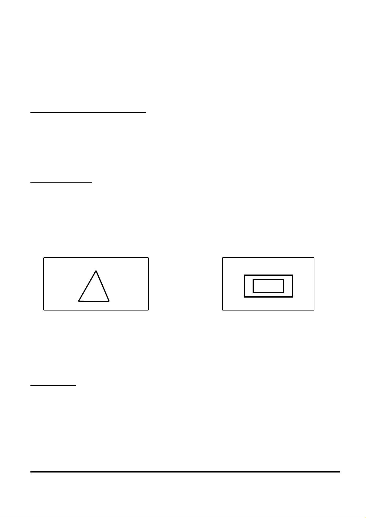
marked with the symbol shown in Fig. 1a in need of replacement, should be replaced strictly in accordance
with the manufacturers instruction, both as to component type and manner of fitting.
!
Fig. 1a Fig. 1b
The above statement is not restricted to safety related components, and engineers should be aware that the
replacement of any components or cabinet part not approved by the manufacturer, could compromise safety
features, or give rise to a safety hazard, which may not be immediately apparent.
Before Testing
Any testing must be carried out with regard to construction and type of equipment. In respect of electrical
protection built into any particular product, it is important to differentiate between products protected by
means of an earth conductor (identified as Class I products) and those solely protected by insulation
(Class II products). Note that Class I products may also have Class II areas, i.e., protection by double or
reinforced insulation in areas where protection is not provided by earthed metal.
Panasonic CS U.K. Document No: 01
Model: General
2
Page 3

TechInfo Sheet fax: 01344 853689
Audio Visual email: av.technical@mail.panasonic.co.uk
Class II products can be identified by the absence of an earth conductor and the symbol shown in Fig. 1b
located on the equipment.
TESTS TO BE CARRIED OUT
Visual Checks
These checks should not be underestimated and should be carried out both prior to and after repair to ensure
both engineer’s and consumer’s safety. The following should be looked for:
1. Casing damage
2. Mains cable damage
3. Loose connections
4. Incorrect wiring of mains plug or inappropriate plug fuse rating
5. Overheating
6. Signs of liquid ingress or foreign matter
7. Unauthorised access
Rather than delay a repair, the above procedures may actually assist in fault diagnosis, as well as identifying
safety hazards.
It is recommended that the results of a visual examination are recorded in detail.
Particular attention should be given to visual checks after repair, to ensure that conductors are not trapped or
exposed by incorrect cabinet fitting.
Mains Plug Fuse Rating
When identifying the fuse rating for the mains plug, the equipment operating instructions should be consulted.
If no guidance is given on fuse type, or advice on plug fitting, repairers are recommended to refer to a leaflet
produced by the Electricity Association Services Ltd, 30 Millbank, London SW1P 4RD
(leaflet no. 1083/6.90).
The following table is given by the Electricity Association and may assist in selecting the correct fuse.
Maximum Input Power Fuse Value
Up to but not exceeding 750 Watts 3A
Greater than 750 but not exceeding 1200 Watts 5A
Greater than 1200 Watts 13A
This table is for guidance only. Surge currents may need to be taken into account (thus, for example,
televisions should be fitted with a 5A fuse in the plug unless otherwise stated in the operating instructions).
Panasonic CS U.K. Document No: 01
Model: General
3
Page 4

TechInfo Sheet fax: 01344 853689
Audio Visual email: av.technical@mail.panasonic.co.uk
Electrical Safety Testing
Electrical safety testing after repair is performed in addition to visual checks, not in substitution. The tests
below are for guidance only, it may not be necessary or possible to carry them out, in other cases additional
tests may be required.
Before carrying out electrical safety tests, the equipment must be disconnected from the mains supply. The
ON/OFF switch however, (if fitted) should be in the ON position. In addition, the product under test should
be disconnected from any other equipment, otherwise misleading results may be obtained.
Detachable Mains Leads
These should be checked separately for end to end polarity, continuity and of course damage.
Protective Earth Continuity
This test applies to Class I only. Any exposed metal parts that could become live by the breakdown of a single
layer of basic insulation must be earthed. This test will check the resistance of the earth path and seek out any
weakness.
A 25A 50Hz AC current (with an open circuit voltage not exceeding 12V) is applied between the earth
connection of the plug and conductive parts of the appliance intended to be earthed. The current is applied for
sufficient time to establish equilibrium and to seek out any potential weakness, such as a stranded earth wire
which will fuse while passing a high current. Poor earthing to the metal casing could show as a high
resistance. The resistance reading should not exceed 0.1 ohm. The actual reading should be recorded.
If the resistance reading exceeds 0.1 ohm, check the integrity of the mains plug earth connection, the earth
supply conductor and the earth termination within the appliance. If they are in order, repeat the test excluding
the mains conductor, that is apply the test between the mains supply earth terminal within the equipment and
other earthed parts.
Equipment with long mains leads (vacuum cleaners for example) will typically have an earth conductor
resistance in excess of 0.1 ohm.
Equipment fitted with a mains lead with a cross sectional area of 0.5mm squared will not withstand a 25A
test current through the earth conductor. In this case, a 10A 50Hz AC current (with an open circuit voltage of
6V) is applied as described above. The resistance reading should not exceed 0.5 ohm, the actual reading
should be recorded. This type of appliance must be fitted with a 3A fuse in the mains plug.
Panasonic CS U.K. Document No: 01
Model: General
4
Page 5

TechInfo Sheet fax: 01344 853689
Audio Visual email: av.technical@mail.panasonic.co.uk
Insulation Resistance
Class I
Apply a 500V DC supply voltage between the live and neutral conductors which are connected together and
the earth connection in the plug.
The insulation resistance should not be less than 2M ohm.
Class II (or Class II areas)
Apply a 500V DC supply voltage between the live and neutral conductors connected together and accessible
metal parts of the equipment. It may be necessary to test several different points in order to check the total
integrity of the insulation.
The insulation resistance should normally not be less than 4M ohm. However, also refer to Test Equipment
Specifications and Special Cases in this document for further guidance. The insulation resistance measurement
should be recorded.
Flash Test
Anyone wishing to apply this test should first contact the manufacturer for advice, since applying this test may
result in damage to the equipment.
Test Equipment Specifications
When purchasing equipment to carry out safety testing, it should be remembered that at some time in the
future, you may be required to produce your test results in a court of law. Any test equipment should
therefore comply with the appropriate standards for measuring instruments. Test equipment must be regularly
calibrated and a calibration certificate obtained from an approved test house.
Home made test equipment is not to be recommended, unless it can be calibrated and an approved calibration
certificate obtained.
A good test instrument will give a metered reading. A PASS/FAIL only indicator is not ideal. Obtaining an
accurate reading provides useful comparison for tests between the same model.
A low reading for a given model/test may result in a pass, but may help to indicate a deterioration of the
insulation necessitating further investigation. Also, in the case of a test failure, the actual reading may help to
establish the reason for the failure.
Panasonic CS U.K. Document No: 01
Model: General
5
Page 6

TechInfo Sheet fax: 01344 853689
Audio Visual email: av.technical@mail.panasonic.co.uk
When using proprietary test equipment, the test parameters and pass limits are often pre-selected. For
example, Class I 500V DC Insulation Resistance pass limits are set to 2M ohm for basic insulation and
Class II to 7M ohm for reinforced insulation. These pass limits would apply to electrical products complying
with the European Norm EN 60 335-1 for example, but not necessarily those complying with other safety
standards. Therefore, before carrying out tests, pass limits should be checked to ensure that erroneous failures
are not indicated.
The voltage applied for the DC Insulation Resistance measurement must be 500 DC. An AC test is applied by
some manufacturers instruments. This is not generally suitable for testing electronic equipment, which
employs capacitive/inductive mains filter components and will result in misleading measurements.
It is recommended that all test results are recorded in a book or on a computer data base and kept for the life
of the equipment. Test results must be regularly audited for the results to be valid.
Special Cases
When checking the insulation resistance on televisions, the test procedure given in the Panasonic Service
Manual should be carried out. This test procedure is based on the original British Standards laid down in
BS 415, which states that the maximum permitted leakage current should not exceed 0.7mA. This current is
detected by measuring the voltage drop across a 2K ohm, 10 Watt resistor connected between accessible
metal parts of the TV and a suitable earthing point, under operating conditions.
Although 0.7mA is not dangerous, it can result in a muscular contraction (which could be dangerous to an
aerial rigger on the roof for example). In addition to the above test the 500V DC insulation resistance
measurement should be applied separately to the aerial socket, the resistance reading should not normally be
less than 2M ohm. However, the shunt resistance connected to the aerial isolator, may be between 0.5-4M
ohm, which may account for an insulation resistance reading less than 2M ohm, on televisions fitted with a
live chassis. This should be checked by referring to the circuit diagram.
CONCLUSIONS
If there is any doubt regarding a safety test, the manufacturer should be consulted. Panasonic will require
full details of the test equipment being used and the model number of the equipment under test. In the case of
equipment failing a safety test, the full test results will be required for analysis. These should be documented
and if possible faxed to our Technical Support Centre in Bracknell on 01344 853689, addressed for the
attention of the Technical Support Manager.
Panasonic CS U.K. Document No: 01
Model: General
6
 Loading...