

Page 1

MANUAL SETTING FIBER SENSOR
Applied for
UL Recognition
Conforming to
EMC Directive
Sensing New Frontiers
Presenting the ultimate in manual-setting fiber sensors.
Equips volume-control variety of sensors with sensitivity.
Page 2

●
●
FX-311 realizes the ultimate in ease-of-operation.
Its operation enables easy and full use of latest technology.
Presenting a product which satisfies professionals using volume control. Besides featuring an operation which makes
full use of the latest functions easy, it provides maximum flexibility in dealing with different situations. FX-311 is, indeed,
a professional fiber sensor.
Simple Realization of Ultimate in Easy-of-operation
Operation indicator
Stability indicator
Operation selection switch
Selectable either
L-ON (Light-ON) or
D-ON (Dark-ON)
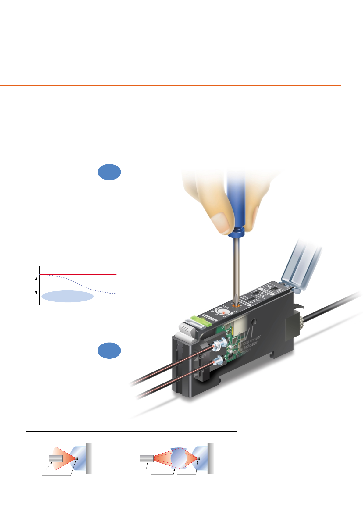
12-turn Potentiometer with Visible Indicator
12-turn potentiometer has been incorporated for fine adjustments.
It enables detection of very fine differences.
Moreover, since the pointer of indicator has a red backlight, its
position can be confirmed at a glance even in a dark area.
Selectable Timer Period of OFF-delay Timer
FX-311 incorporates an OFF-delay timer. It is useful when the
connected device has a slow response time or when small objects
are being sensed and the output signal width is small. The timer
period can be selected not only 40ms but also 10ms. It is also
suitable for increased PLC speeds.
Selectable Between Three Modes According to Application
The most suitable sensing mode can be selected according to the
application from three different modes with the mode selection
switch.
Selectable between three modes
Applications
• When using long-range mode
Sensing the presence
of a translucent sheet
•
When using reduced intensity mode
Detecting PCB rack
Long-range mode
(LONG)
Used in case long distance sensing is required.
(Response time: 2ms)
Used for general sensing application.
(Response time: 250!s)
Standard mode
(STD)
Reduced
intensity
mode
(S-D)
Since the emitted light amount is restricted in this mode, it is
suitable for delicate sensing, such as when the received light
is saturated due to too short a sensing distance or when
detecting translucent objects, etc. (Response time: 250!s)
FT-KV8
FD-FM2
Reflective tape
RF-12
1
Page 3

L-ON/D-ON/L-ON
1
2
3
A
A
ON
B
OFF
A
B
Easy Adjustment with ‘Assist Function’ for Knowing
Optimum Sensitivity
FX-311 has a built-in convenient ‘assist function’ which indicates the optimum
sensitivity position by the rapid flashing of the indicator at the time of sensitivity
adjustment. This enables easy and reliable sensitivity adjustment, which is
convenient for a narrow sensing range requiring fine tuning.
Easy Operation by Using a Convenient, Hand-turned
Adjusting Knob of Hand-turned Knob Attached Cover
An optional hand-turned knob attached cover (FX-AJ1/AJ1P) is
available, which makes a screwdriver unnecessary. On-site
adjustment of sensitivity can be done at any time quickly and easily.
Now It’s Possible to Simultaneously Cut Two
Fibers to the Same Length
Each fiber (with some exceptions) has a newly developed two-in-one
fiber attachment
(FX-AT2/AT3/AT4/AT5/AT6)
which enables two
fibers to be cut simultaneously to the same length with the new fiber
cutter (FX-CT2).
Also, since the fibers can be attached to the
amplifier while being fixed in position in the two-in-one fiber
attachment, sensitivity changes due to variation in the amount of
fiber insertion do not occur.
2
m
In order to make ‘assist function’ effective, switch the operation selection switch in the order .
Find the point A where the sensor
is switched ON in the sensing
condition.
Optimum sensitivity point
located.
Sensing (beam received)
condition
Non-sensing (beam not
received) condition
The pointer
flashes once
at the point A.
The pointer
flashes twice
at the point B.
Confirm the operation
indicator lights up.
Detectable range
The pointer
flashes faster
at the optimum
sensitivity.
ON
Innovative
feature
Sensing methed
Sensing methed
In the non-sensing condition, turn the
adjuster until ON state again, turn the
adjuster counterclockwise and find the
point
B
where it is switched OFF.
Page 4
3
Innovative product based on FX-301 design concepts.
Advanced manual setting fiber sensor.
Utilizes the Most Advanced Optical
Technology Offered by SUNX
The original SUNX optical technology developed for the FX-301 digital fiber
sensor, including its benefits of simple maintenance, reduced wiring and
easy installation, is taken a step further with FX-311.
FX-311 incorporates technology to handle every major concern and deliver
superior performance for a variety of on-site requirements.
Long Life and Stable
Operational Settings
Assure Dependable Performance
Newly
developed
The light-emitting elements of conventional
fiber sensors are affected by temperature
and long-term use, changing their emission
over time and requiring sensitivity
readjustment. FX-311 uses the newly
developed ‘LED using four chemical
elements’, a new LED first used in FX-301.
This emitter greatly reduces adverse
influences on emission performance,
resulting in stable operation that almost
never needs adjustment.
No performance
deterioration over time
No reduced life
expectancy for elements
Newly developed
light emitting
element
Conventional light emitting element
Light emission decreases over time,
adversely effecting sensing operations.
Time
High
Low
Emitted
light
intensity
Conventional fiber sensor system (without lens)
FX-311 (built-in double coupling lens)
Low efficiency due to the diffusion and loss of emitted
light.
The light emission efficiency is increased tremendously,
as light is now collected and focused into the fiber by the lens.
Double
coupling lens
Fiber
Fiber
Light emitting element
Light
emitting element
The new developed optical ‘double coupling
lens’ has been incorporated directly into the
fiber sensor itself. This lens maximizes the
light emission efficiency, resulting in a
tremendous improvement in the sensing
range. Sensing ranges with small diameter
fiber and ultra-small diameter fiber, which
have become very popular in recent years
due to the miniaturization of chip
components, have been increased by 50%
over previous values achieved with other
amplifiers.
Innovative
feafure
Long-range Sensing
Made Possible with
Built-in Optical Lens
Page 5
Digital fiber sensor FX-301 is
now available also!
Digital fiber sensor FX-301 is
now available also!
● Easy operation with MODE NAVI
● Super high-speed response (150!s)
● Optional communication function enables copying
and saving
4
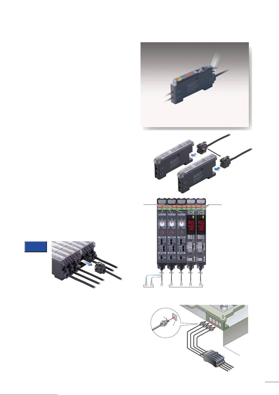
Side-by-side Connection with FX-301 Is also Possible
for Wide-saving and Quick Installation
mNOTE
Note that settings other than that
of the interference prevention
function cannot be transmitted
between this product and digital
fiber sensor FX-301(P).
Therefore, in case both models
of amplifiers are mounted in
cascade, make sure to mount
identical models together.
FX-301FX-311
FD-FM2
Tag
Specially Designed for Flexible Use
and Simple Operation
Maintenance Made Easy with Quick-connection Cables
Both main and sub units utilize the same amplifier body. This
feature allows for easy mounting in the side-by-side configuration,
because main and sub unit functions are distinguished only by the
proper use of 3-core main cable for the main unit and 1-core sub
cable for each sub unit. Moreover, due to the utilization of the same
main body for both main and sub units, inventory management and
maintenance, is simplified.
Each sub cable is a single output wire, reducing wiring and
simplifying installation. Quick-connection cables are the same type
as used on the FX-301, facilitating side-by-side connection. Further,
the connectors are slide type, allowing removal without shifting
amplifier positions. This eliminates the need to provide extra
maintenance space around the amplifiers.
Close Mounting Is Possible for up to
Four Fiber Heads
If amplifiers are mounted side-by-side in cascade, the optical
communication function automatically sets different emission timing
for the amplifiers, at the time of switching on the power supply. Up to
four fiber heads can be mounted closely, without mutual interference.
FX-301 units can also be used in these configurations.
Main cable
Main cable
Power supply
wires 2 Nos.
Sub cables are just
single output wires.
Output wire
Sub cable
Sliding connectors
are easy to insert
and remove
Page 6

5
ORDER GUIDE
OPTIONS
Amplifiers
Appearance Emitting element
Red LED
OutputModel No.
FX-311
FX-311P
Quick-connection cables
Type DescriptionModel No.
CN-73-C1
CN-73-C2
CN-73-C5
NPN open-collector
transistor
PNP open-collector
transistor
Main cable
0.2mm
2
3-core cabtyre cable, with connector on one end
Cable outer diameter: "3.8mm "0.15in
0.2mm
2
1-core cabtyre cable, with connector on one end
Cable outer diameter: "3.8mm "0.15in
CN-71-C1
CN-71-C2
Sub cable
CN-71-C5
Length: 1m
3.281ft
Length: 2m
6.562ft
Length: 5m
16.404ft
Length: 1m
3.281ft
Length: 2m
6.562ft
Length: 5m
16.404ft
Designation
Description
Model No.
MS-DIN-2
Amplifier mounting
bracket
Fiber sensor amplifier
protection seal
Mounting bracket for amplifier
Hand-turned knob allows easy
adjustment of sensor sensitivity.
FX-AJ1
FX-AJ1P
FX-MB1
MS-DIN-E
Hand-turned knob
attached cover
Amplifier mounting
bracket
Hand-turned knob attached
cover
Fiber sensor amplifier
protection seal
End plates are not supplied with the amplifier. Please order it separately when the amplifiers are mounted in cascade.
Quick-connection cable is not supplied with the amplifier. Please order it separately.
Please order the quick-connection cable separatebly.
When connecting multiple amplifiers, these end plates ensure
that all amplifiers are mounted together in a secure and fully
connected manner.
Two Nos. per set
End plates
Appearance Model No. Description
Communication
window seal
Connector seal
For NPN output type
For PNP output type
10 sets of 2 communication window seals and 1 connector seal
Communication window seal:
It prevents malfunction due to transmission signal from another
amplifier, as well as, prevents effect on another amplifier.
Connector seal:
It prevents contact of any metal, etc., with the pins of the quickconnection cable.
Page 7

6
Type
Shape of fiber head
(mm) (in)
:
STD
:
S-D
:
LONG
[]
][
Sensing range
(Note 1)
Features
: Free-cut
Fiber cable
length
Allowble
bending
radius
Model No.
Min. sensing object
under the optimum
condition (Note 3)
3) The optimum condition is the condition when the sensitivity is set so that the output just changes to light
incident operation in the object absent condition.
"0.03mm
"0.001in
opaque object
"0.03mm
"0.001in
opaque object
"0.04mm
"0.002in
opaque object
"0.03mm
"0.001in
opaque object
"0.02mm
"0.001in
opaque object
"0.04mm
"0.002in
opaque object
"0.02mm
"0.001in
opaque object
"0.03mm
"0.001in
opaque object
"0.03mm
"0.001in
opaque object
"0.03mm
"0.001in
opaque object
"0.02mm
"0.001in
opaque object
"0.02mm
"0.001in
opaque object
"0.025mm
"0.001in
opaque object
"0.03mm
"0.001in
opaque object
"0.03mm
"0.001in
opaque object
Long sensing
range
Long sensing
range
Standard
With lens
Sharp bend
Small diameter
Standard
Small fiber
head
Small diameterFlexible
Economy
Notes: 1) Please take care that the sensing range of the free-cut type fiber may be reduced by 20% max. depending upon how the fiber is cut.
Notes: 2) Fiber cutter is not supplied as accessory along with standard (economy) fibers. Please order it separately.
M4
Lens mountable
Lens mountable
M4
With sleeve
M4
"1.48
"0.058
"2.5
"0.098
M4
M4
M3
M3
With sleeve
M3
"0.88
"0.035
"1.5
"0.059
M4
"2.5
"0.098
M3
"1.5
"0.059
"3
"0.118
123
39.37
9.843
Front sensing
M4
Small diameter
M3
Small diameter
"1.5
"0.059
• 1.5 times approx. the sensing
range as standard type
• Suitable for detection in a
congested equipment
• Free-cut type
• The fiber can be bent
sharply, like an electric wire,
to avoid space wastage in
installation because of its
small allowable bending
radius of R1mm R0.039in or
more.
• Allowable bending radius:
R4mm R0.157in or more
• Bending durability:
one million times or more
at R4mm R0.157in,
FT-P80: at R10mm R0.394in
• Installs with M2 screws,
allowing easy beam axis
alignment
• Allowable bending radius:
R4mm R0.157in or more
• Bending durability:
one million times or more
(at R10mm R0.349in)
• Low price & free-cut
• Miniature head but having
the same sensing range as
the standard type fiber
• Free-cut type
2m
2m
R25mm
R0.984in
or more
2m
(Note 2)
2m
R25mm
R0.984in
or more
R25mm
R0.984in
or more
R1mm
R0.039in
or more
R4mm
R0.157in
or more
1m
3.281ft
FT-B8
FT-FM2
FT-FM2S
With sleeve 90mm 3.543in
FT-NFM2S
With sleeve 90mm 3.543in
FT-FM2S4
With sleeve 40mm 1.575in
FT-NFM2S4
With sleeve 40mm 1.575in
FT-SFM2
FT-NB8
FT-N8
FT-T80
FT-NFM2
FT-SNFM2
FT-W8
FT-WS8
FT-W4
FT-WS4
FT-WS8L
FT-P80
FT-Z8
FT-P40
FT-P2
FT-Z8E
FT-Z8H
Top sensing
Side sensing
128
39.37
26.247
812
26.247
39.37
700mm 27.559in
360mm 14.173in
126mm 4.961in
160mm 6.299in
80mm 3.15in
28mm 1.102in
650mm 25.591in
320mm 12.598in
110mm 4.331in
250mm
100mm
250mm 9.843in
100mm 3.937in
35mm 1.378in
280mm 11.024in
120mm 4.724in
42mm 1.654in
270mm 10.63in
140mm 5.512in
49mm 1.929in
1,200mm 47.244in
600mm 23.622in
210mm 8.268in
1,000mm 39.37in
480mm 18.898in
168mm 6.614in
570mm 22.441in
290mm 11.417in
100mm 3.937in
1,600mm 62.992in
800mm 31.496in
280mm 11.024in
2,700mm 106.299in
1,400mm 55.118in
490mm 19.291in
800mm 31.496in
400mm 15.748in
140mm 5.512in
780mm 30.709in
400mm 15.748in
130mm 5.118in
ORDER GUIDE
General use fibers [Thru-beam type (one pair set)]
1,100mm 43.307in
530mm 20.866in
180mm 7.087in
780mm 30.709in
400mm 15.748in
130mm 5.118in
6.562ft
6.562ft
6.562ft
6.562ft
2m
6.562ft
2m
6.562ft
2m
6.562ft
2m
6.562ft
Lens mountable
Lens mountable
Lens mountable
Page 8

• Ultra-small diameter heads,
very narrow beam
"0.125mm "0.005in
• Ultra-small diameter heads,
very narrow beam "0.25mm
"0.01in
• Aperture angle 2
• Laser beam equivalent
detection
• Aperture angle 2
• Side-view type
"0.4mm
"0.016in
opaque object
"0.02mm
"0.001in
opaque object
"0.02mm
"0.001in
opaque object
"0.04mm
"0.002in
opaque object
"0.02mm
"0.001in
opaque object
"0.02mm
"0.001in
opaque object
"0.02mm
"0.001in
opaque object
"0.02mm
"0.001in
opaque object
"0.02mm
"0.001in
opaque object
Horizontal: "0.025mm
Horizontal "0.001in
Horizontal : opaque object
Vertical:
"0.45mm
Horizontal "0.018in
Horizontal :opaque object
Horizontal: "0.025mm
Horizontal : "0.001in
Horizontal : opaque object
Vertical: "0.45mm
Horizontal"0.018in
Horizontalopaque object
FT-FM10L
Wide beamArray
Long sensing
range with lens
ElbowSide-view
Ultra-small
diameter
Narrow beam
10m
Notes: 1) Please take care that the sensing range of the free-cut type fiber may be reduced by 20% max. depending upon how the fiber is cut.
Notes:
2) The optimum condition is the condition when the sensitivity is set so that the output just changes to light
incident operation in the object absent condition.
Side sensing
FT-SFM2L
2m
R25mm
R0.984in
or more
R25mm
R0.984in
or more
FT-A8
FT-AFM2
FT-AFM2E
2m
R25mm
R0.984in
or more
FT-R80
2m
R25mm
R0.984in
or more
R5mm
R0.197in
or more
FT-V22
FT-V41
FT-SFM2SV2
FT-E12
FT-E22
FT-K8
"0.06mm
"0.002in
opaque object
FT-KV8
2m
R25mm
R0.984in
or more
"2.5 "0.098
Top sensing
• Large lenses on the fiber
heads increase the sensing
range significantly.
• Fiber cable length 10m
32.808ft each
• The wide beam detects an
object at any place within the
range.
• Long sensing range with
small fiber heads of "2.5mm
"0.099in
2m
• The wide beam detects an
object at any place within the
range.
• Long-distance detection is
possible.
M14
3113.5
1.220.531
15
0.591
Small diameter
Sleeve part cannot be bent.
Sleeve part cannot be bent.
Sleeve part cannot be bent.
Sleeve part cannot be bent.
15
0.591
• The fiber head is bent at a
right angle with 5mm
0.197in bending radius.
1m
500mm
19.685in
1m
3.281ft
2m
R25mm
R0.984in
or more
• The side-view sensing
enables it to be used in a
small space.
M4
"1
(FT-V22: "2 "
0.079
)
"2.5
0.6
0.024
0.8
"1.5
"0.059
"2.5
"0.099
"3"0.25
"3"0.4
"3.5 "3.7
"4
3
1,600mm 62.992in
800mm 31.496in
280mm 11.024in
3,000mm
118.11in
1,500mm 59.055in
520mm 20.472in
650mm 25.591in
330mm 12.992in
115mm 4.528in
590mm 23.228in
290mm 11.417in
100mm 3.937in
530mm 20.866in
230mm 9.055in
80mm 3.15in
390mm 15.354in
180mm 7.087in
63mm 2.48in
175mm 6.89in
80mm 3.15in
27mm 1.063in
400mm 15.748in
200mm 7.874in
70mm 2.756in
2,000mm 78.74in
1,000mm 39.37in
350mm 13.78in
80mm 3.15in
50mm 1.969in
15mm 0.591in
18mm 0.709in
10mm 0.394in
3mm 0.118in
19,500mm 767.715in
14,000mm 551.18in
3,800mmm 149.606in
Type
Shape of fiber head
(mm) (in)
:
STD
:
S-D
:
LONG
[]
][
Sensing range
(Note 1)
Features
: Free-cut
Fiber cable
length
Allowble
bending
radius
Model No.
Min. sensing object
under the optimum
condition (Note 2)
ORDER GUIDE
Special use fibers [Thru-beam type (one pair set)]
"
0.039"0.098
"0.01
"0.016
"0.118
"0.118
"0.138
"0.157
"0.146
32.808ft
6.562ft
6.562ft
6.562ft
6.562ft
3.281ft
6.562ft
6.562ft
7
0.031
0.118
Lens mountable
Page 9

8
Type
Shape of fiber head
(mm) (in)
:
STD
:
S-D
:
LONG
[]
][
Sensing range
(Note 1)
Features
: Free-cut
Fiber cable
length
Allowble
bending
radius
Model No.
Min. sensing object
under the optimum
condition (Note 2)
Notes: 1) Please take care that the sensing range of the free-cut type fiber may be reduced by 20% max. depending upon how the fiber is cut.
2) The optimum condition is the condition when the sensitivity is set so that the output just changes to light
incident operation in the object absent condition.
"0.04mm
"0.002in
opaque object
"0.02mm
"0.001in
opaque object
"0.04mm
"0.002in
opaque object
"0.06mm
"0.002in
opaque object
"0.08mm
"0.003in
opaque object
"0.08mm
"0.003in
opaque object
"0.02mm
"0.001in
opaque object
"0.02mm
"0.001in
opaque object
FT-H35-M2
FT-H35-M2S6
With sleeve 60mm 2.362in
FT-H20W-M1
FT-H20W-M2
FT-H20-M1
FT-H13-FM2
FT-L8Y
FT-V8Y
FT-6V
FT-60V
With sleeve
2m
6.562ft
2m
6.562ft
2m
6.562ft
1m
3.281ft
1m
3.281ft
1m
3.281ft
1m
3.281ft
R10mm
R0.394in
or more
R25mm
R0.984in
or more
R25mm
R0.984in
or more
R30mm
R1.181in
or more
R200mm
R7.874in
or more
R30mm
R1.181in
or more
Heat-resistant
Chemical-resistant
Vacuum
•
Flexible cable with silicone jacket
•
Heat-resistant temp.: 200C 392F
Cold-resistant temp.:60C 76F
•
Heat-resistant temp.: 130C 266F
Cold-resistant temp.:60C 76F
• Free-cut type
• Usable in chemical solvents
•
Heat-resistant specification (115C 239F)
• Long sensing range with lens
• Usable in chemical solvents
• Rectangular head with no
beam misalignment
• Usable in chemical solvents
•
Heat-resistant specification (115C 239F)
• Side-view type
• Usable in vacuum chamber
• Heat-resistant temp.: 120C
248F
• Heat-resistant temp.: 350C
662F
Cold-resistant temp.:60C
76F
• Heat-resistant temp.:200C
392F
Cold-resistant temp.:60C
76F
M4
M4
"2.1 "0.083
M4
M4
M4
2m
"5.5
"0.217
"5.5
"0.217
M4
The vacuum type fiber must be used with the following products as a set.
FT-J6: Fiber at atmospheric side (one pair set)
FV-BR1: Photo-terminal (one pair set)
Semi-standard fibers (Custom-order made)
The fiber cable length or sleeve length of the standard fibers can be modified at your request. Select the fiber cable length (symbol ) or the sleeve
length (symbol ) from the table below.
Type
Basic model No.
Standard threaded
head (free-cut)
2 6.562, 3 9.843
20 65.617, 30 98.425
3 9.843
Small diameter
threaded head with
sleeve (free-cut)
200C 392F
heat-resistant
With large diameter lens
350C 662F
heat-resistant
With sleeve
550mm 21.654in
280mm 11.024in
90mm 3.543in
310mm 12.205in
140mm 5.512in
50mm 1.969in
550mm 21.654in
280mm 11.024in
90mm 3.543in
880mm 34.646in
440mm 17.323in
155mm 6.102in
3,500mm 137.795in
1,500mm 59.055in
530mm 20.866in
3,500mm
137.795in
1,500mm 59.055in
530mm 20.866in
800mm 31.496in
400mm 15.748in
140mm 5.512in
470mm 18.504in
230mm 9.055in
80mm 3.15in
220mm 8.661in
100mm 3.937in
35mm 1.378in
□
□
f
1315
0.5120.591
"4mm
"0.157in
opaque object
5m
7m
FT-Z802Y
FT-Z805Y
FT-Z807Y
R25mm
R0.984in
or more
5
16.4041032.8081549.213
20
65.617
0
0.4
0.8
0.2
0.6
1.2
1.0
25
82.0213098.425
Sensing range
attenuation coefficient
Fiber cable length
# (m)
(ft)
• Correlation between sensing range attenuation
• coefficient and fiber cable length
Longer the fiber cable,
shorter is the sensing
range.
ORDER GUIDE
Environment resistant fibers [Thru-beam type (one pair set)]
6.562ft
2m
6.562ft
16.404ft
22.966ft
3 9.843, 4 13.123,
5 16.404, 10 32.808,
15 49.213, 20 65.617,
25 82.021, 30 98.425
2 6.562 (Note), 3 9.843,
4 13.123, 5 16.404, 10 32.808,
15 49.213, 20 65.617,
25 82.021, 30 98.425
1 0.394 , 2 0.787, 3 1.181,
4 1.575, 5 1.969, 6 2.362,
7 2.756, 8 3.15, 9 3.543,
10 3.937, 11 4.331, 12 4.724
1 0.394, 2 0.787, 3 1.181,
4 1.575, 5 1.969, 6 2.362,
7 2.756, 8 3.15, 9 3.543,
10 3.937, 11 4.331, 12 4.724
FT-FM
FT-FM -S
FT-FM L
FT-H20-M
FT-H35-M
□
□
□
□
f
□
f
□
FT-NFM2-S
f
□
Fiber cable length
(Unit: m ft)
Sleeve length
(Unit: cm in)
□
□
f
Type
Note: The standard fiber has a 2m 6.562ft fiber cable length and a 4cm 1.575in or 9cm
3.543in sleeve length.
Lens mountable
Lens mountable
Lens mountable
Lens mountable
Lens mountable
Page 10

Type
Shape of fiber head
(mm) (in)
:
STD
:
S-D
:
LONG
[]
][
Sensing range
(Note 1,2)
Features
:
Free-cut
Fiber cable
length
Allowble
bending
radius
Model No.
Min. sensing object
at the maximum
sensitivity (Note 3)
"0.02mm
"0.001in
gold wire
"0.02mm
"0.001in
gold wire
"0.02mm
"0.001in
gold wire
"0.02mm
"0.001in
gold wire
"0.02mm
"0.001in
gold wire
"0.02mm
"0.001in
gold wire
"0.02mm
"0.001in
gold wire
"0.02mm
"0.001in
gold wire
"0.02mm
"0.001in
gold wire
"0.02mm
"0.001in
gold wire
"0.02mm
"0.001in
gold wire
"0.02mm
"0.001in
gold wire
"0.02mm
"0.001in
gold wire
"0.02mm
"0.001in
gold wire
"0.02mm
"0.001in
gold wire
"0.02mm
"0.001in
gold wire
"0.02mm
"0.001in
gold wire
"0.02mm
"0.001in
gold wire
FD-B8
Long sensing
range
Economy
Standard
Small head
High precision
Small diameter
with sleeve
Small
diameter
StandardSmall fiber headSmall diameterFlexible
Sharp bend
2m
2m
FD-5
FD-FM2
FD-N8
FD-N4
FD-FM2S
With sleeve 90mm 3.543in
FD-FM2S4
With sleeve 40mm 1.575in
500mm
19.685in
1m
3.281ft
R25mm
R0.984in
or more
R25mm
R0.984in
or more
R25mm
R0.984in
or more
R1mm
R0.039in
or more
R2mm
R0.079in
or more
R4mm
R0.157in
or more
M6
Coaxial
With sleeve
Small diameter
Small diameter
FD-T80
FD-T40
• As fiber cutting is not required,
sensing range will not be reduced.
• Free-cut type
• Low price & free-cut
• Miniature head but having the
same sensing range as the
standard type fiber
• Long sensing range
• Free-cut type
FD-S80
FD-W8
FD-W44
FD-WT8
FD-WS8
FD-WT4
FD-WG4
FD-WSG4
FD-P80
FD-P60
FD-P50
FD-P40
FD-P2
2m
FD-NFM2
FD-NFM2S
With sleeve 90mm 3.543in
• Suitable for detection in a
congested equipment
• Free-cut type
FD-NFM2S4
With sleeve 40mm1.575in
FD-SNFM2
With sleeve
With sleeve
Lens mountable
Small
diameter
M6
"2.5 "0.098
M6
M4
M4
M3
"3 "0.118
M4
M4
"1.48 "0.058
"2.5 "0.098
M6
M4
"1.48 "0.058
M4
"3 "0.118
M3
M4
Coaxial
"3 "
0.118
"3 "0.118
M6
Small
diameter
M3
M4
"1.5 "0.059
M6
480mm 18.898in
220mm 8.661in
75mm 2.953in
310mm 12.205in
140mm 5.512in
47mm 1.85in
270mm 10.63in
110mm 4.331in
39mm 1.535in
260mm 10.236in
120mm 4.724in
42mm 1.654in
270mm 10.63in
110mm 4.331in
39mm 1.536in
270mm 10.63in
110mm 4.331in
39mm 1.536in
30mm 1.181in
15mm 0.591in
5mm 0.197in
30mm 1.181in
15mm 0.591in
5mm 0.197in
190mm 7.48in
90mm 3.543in
32mm 1.26in
190mm 7.48in
90mm 3.543in
32mm 1.26in
220mm 8.661in
100mm 3.937in
35mm 1.378in
65mm 2.559in
32mm 1.26in
11mm 0.433in
90mm 3.543in
45mm 1.772in
16mm 0.63in
90mm 3.543in
45mm 1.772in
16mm 0.63in
90mm 3.543in
45mm 1.772in
16mm 0.63in
36mm 1.417in
18mm 0.709in
6mm 0.236in
50mm 1.969in
25mm 0.984in
9mm 0.354in
75mm 2.953in
38mm 1.496in
13mm 0.512in
Coaxial
2m
6.562ft
(Note 3)
ORDER GUIDE
General use fibers [Reflective type]
6.562ft
2m
6.562ft
6.562ft
2m
6.562ft
2m
6.562ft
6.562ft
9
Notes: 1)
The sensing range is specified for white non-glossy paper [100100mm 3.9373.937in (FD-B8, FD-5, FD-FM2, FD-FM2S, FD-FM2S4, FD-N8, FD-T80 and FD-S80: 400400mm 15.74815.748in,
FD-N4, FD-T40, FD-NFM2, FD-NFM2S, FD-NFM2S4, FD-SNFM2, FD-W8, FD-WT8, FD-WS8, FD-P80, FD-P60 and FD-P50: 200200mm 7.8747.874in)] as the object.
Notes: 2) Please take care that the sensing range of the free-cut type fiber may be reduced by 20% max. depending upon how the fiber is cut.
Notes: 3) Fiber cutter is not supplied as accessory along with standard (economy) fibers. Please order it separately.
4)
The minimum sensing object is specified for maximum sensitivity. Also, note that the corresponding setting distance is different from the rated sensing distance.
• The fiber can be bent
sharply, like an electric wire,
to avoid space wastage in
installation because of its
small allowable bending
radius of R1mmR0.039in or more.
FD-WG4, FD-WSG4:
R2mm R0.079in or more
Sleeve part of FD-W44:
R10mm 0.394in or more
• Allowable bending radius:
R4mm R0.157in or more
• Bending durability:
one million times or more
at R10mm 0.394in,
FD-P40 or FD-P2:
at R4mm R0.157in
Page 11

Type
Shape of fiber head
(mm) (in)
:
STD
:
S-D
:
LONG
[]
][
Sensing range
(Note 1,2)
Features
:
Free-cut
Fiber cable
length
Allowble
bending
radius
Model No.
Min. sensing object
at the maximum
sensitivity (Note 3)
Coaxial
Sleeve part cannot be bent.
1814
0.709
0.551
24
21
0.9945
0.827
1513
0.591
0.512
(Liquid)
(Liquid)
Applicable pipe diameter: Outer dia. "6 to
"26mm "0.236 to "1.024in transparent pipe
Applicable pipe diameter: Outer dia. "6 to
"26mm"0.236 to "1.024in transparent pipe
PVC, fluorine resin, PC,
acrylic, glass, wall thickness
1 to 3mm 0.039 to 0.118in
PFA (fluorine resin) or
equivalently transparent pipe,
wall thickness 1mm 0.039in
FD-L4
FD-L43
FD-L41
FD-L42
FD-G4
FD-EG1
FD-AFM2
FD-AFM2E
Lens mountable
Lens mountable
Top sensing
Side sensing
Small diameter
Coaxial
Sleeve part cannot be bent.
Sleeve part cannot be bent.
Sleeve part cannot be bent.
Sleeve part cannot be bent.
Coaxial
Coaxial·small diameter
Specular object
detection
Fixed-focus reflective
High precisionArrayElbowSide-viewUltra-small diameter
Mountable on pipe
Standard
For PFA, wall thickness 1mm 0.039in pipe
Liquid level
sensing
2m
2m
5m
500mm
6.562ft
2m
6.562ft
2m
6.562ft
2m
6.562ft
2m
6.562ft
6.562ft
2m
6.562ft
2m
6.562ft
16.404ft
5m
16.404ft
19.685in
500mm
19.685in
1m
3.281ft
1m
3.281ft
R10mm
R0.394in
or more
R10mm
R0.394in
or more
R10mm
R0.394in
or more
R10mm
R0.394in
or more
R4mm
R0.197in
or more
R25mm
R0.079in
or more
R25mm
R0.079in
or more
R25mm
R0.079in
or more
R25mm
R0.079in
or more
R25mm
R0.079in
or more
FD-R80
FD-V41
FD-SFM2SV2
FD-EN500S1
FD-ENM1S1
FD-E12
FD-E22
FD-F8Y
FD-F41
FD-F91
FD-F4
FD-F9
M4
M3
□ 20 □ 0.787
□ 20
□ 0.787
M6
"1.5 "0.059
"3 "0.118
0.7
"2 "0.079
"0.5 "0.02
"1.5 "0.059
"0.65 "0.026
"3 "0.118
"5 "0.197
0.8
"0.5 "0.02
M3
M3
"0.8 "0.031
"6 "0.236
"5 "0.197
2520
0.984
0.787
• Detection is not affected by
object color.
• Just 4mm 0.15in thick
• Glass substrate is reliably
detected.
•
Just 3mm 0.118in thick
•
Wafer is reliably detected.
• Just 3.8mm 0.15in thick
• Glass substrate is reliably
detected.
• Precise position sensing with
coaxial fiber
• Its wide beam meets various
needs.
• The fiber head is bent at a
right angle with 5mm 0.197in
bending radius at the neck.
• The side view sensing
enables it to be used in a
small space.
• Suitable for detection in a
very congested equipment
• Easy fine adjustment of the
installation position.
• Precise position sensing with
coaxial fiber
• Reduces malfunction due to
liquid drop at the tip.
• Liquid level is reliably
detected from outside the
pipe.
• Precise position sensing with
coaxial fiber
•
Combination with the FX-MR3 lens
gives an extremely small spot diameter
of "0.3mm "0.012in approx.
Sleeve part cannot be bent.
"0.02mm
"0.001in
gold wire
(LCD glass)
"0.02mm
"0.001in
gold wire
"0.02mm
"0.001in
gold wire
"0.02mm
"0.001in
gold wire
"0.02mm
"0.001in
gold wire
"0.02mm
"0.001in
gold wire
"0.02mm
"0.001in
gold wire
"0.02mm
"0.001in
gold wire
"0.02mm
"0.001in
gold wire
"0.02mm
"0.001in
gold wire
"0.02mm
"0.001in
gold wire
"0.02mm
"0.001in
gold wire
2 to18mm 0.079 to 0.709in
4.5 to12mm 0.177 to 0.473in
4.8 to 9.5mm 0.189 to 0.374in
2 to16mm 0.079 to 0.63in
3 to14mm 0.118 to 0.551in
6.5 to11mm 0.256 to 0.433in
110mm 4.331in
55mm 2.165in
19mm 0.748in
38mm 1.496in
18mm 0.709in
6mm 0.236in
220mm
8.661in
110mm 4.331in
39mm 1.536in
185mm 7.284in
85mm 3.347in
30mm 1.181in
55mm 2.165in
25mm 0.984in
9mm 0.354in
100mm 3.937in
45mm 1.772in
16mm 0.63in
45mm 1.772in
23mm 0.906in
7mm 0.276in
38mm 1.496in
18mm 0.709in
6mm 0.236in
5mm 0.197in
3mm 0.118in
Unusable
11mm 0.433in
6mm 0.236in
1mm 0.039in
0.5 to4mm 0.02 to 0.158in
1to 3mm 0.039 to 0.118in
1.8 to 2.5mm 0.071 to 0.099in
Convergent point:
6mm 0.236in
(
(
Convergent point:
8mm 0.315in
(
(
Convergent point:
2mm 0.079in
(
(
0 to 20mm 0 to 0.787in
1729
0.669
1.142
Glass substrate
detection
ORDER GUIDE
Special use fibers [Reflective type]
10
0.028
0.031
Notes: 1) The sensing range is specified for white non-glossy paper [100100mm 3.9373.937in (FD-G4, FD-AFM2, FD-AFM2E, FD-R80 and FD-SFM2SV2:
200
200mm 0.1570.157in, FD-L43: glass substrate 7652t1.1mm 0.1970.236t0.043in, FD-L41: glass substrate 100100t2mm
3.937
3.937t0.079in)] as the object.
Notes: 2) Please take care that the sensing range of the free-cut type fiber may be reduced by 20% max. depending upon how the fiber is cut.
3) The minimum sensing object is specified for maximum sensitivity. Also, note that the corresponding setting
distance is different from the rated sensing distance. However, in the case of fixed-focus reflective type,
when the sensitivity is at MAX., it is only possible to detect the minimum size of sensing object at a distance
of convergent point.
Page 12

Notes: 1) The sensing range is specified for white non-glossy paper [400400mm 15.74815.748in (FD-6V: 200200mm 7.8747.874in) ] as the object.
Notes: 2) Please take care that the sensing range of the free-cut type fiber may be reduced by 20% max. depending upon how the fiber is cut.
3) The minimum sensing object is specified for maximum sensitivity. Also, note that the corresponding setting
distance is different from the rated sensing distance.
The vacuum type fiber must be used with the following products as a set.
FT-J6: Fiber at atmospheric side (one pair set)
FV-BR1: Photo-terminal (one pair set)
FD-H35-M2
FD-H35-M2S6
With sleeve 60mm 2.362in
FD-H20-M1
FD-H13-FM2
FD-6V
Coaxial
With sleeve
Coaxial
Heat-resistant
Vacuum
2m
6.562ft
1m
3.281ft
1m
3.281ft
R25mm
0.984in
or more
R200mm
7.874in
or more
•
Heat-resistant temp.: 350C 662F
Cold-resistant temp.:
60C 76F
•
Flexible cable with silicone jacket
•
Heat-resistant temp.: 200C 392F
•
Cold-resistant temp.:
60C 76F
•
Heat-resistant temp.: 130C 266F
•
Cold-resistant temp.:
60C 76F
• Free-cut type
• Usable in vacuum chamber
•
Heat-resistant temp.: 120C 248F
M6
M6
"2.8 "0.11in
M6
M6
M6
Semi-standard fibers (Custom-order made)
The fiber cable length or sleeve length of the standard fibers can be modified at your request. Select the fiber cable length (symbol ) or the sleeve
length (symbol ) from the table below.
FD-FM
Standard threaded
head (free-cut)
2 6.562, 3 9.843
3 9.843
Small diameter
threaded head with
sleeve (free-cut)
200C 392F
heat-resistant
350C 662F
heat-resistant
With sleeve
FD-FM -S
FD-NFM2-S
FD-H20-M
FD-H35-M
• Correlation between sensing range attenuation
• coefficient and fiber cable length
Longer the fiber cable,
shorter is the sensing
range.
"0.02mm
"0.01in
gold wire
"0.02mm
"0.01in
gold wire
"0.02mm
"0.01in
gold wire
"0.02mm
"0.01in
gold wire
310mm 12.205in
140mm 5.512in
47mm 1.85in
310mm 12.205in
140mm 5.512in
47mm 1.85in
310mm 12.205in
140mm 5.512in
47mm 1.85in
165mm 6.496in
75mm 2.953in
26mm 1.024in
Accessaries (attached with fibers)
Fiber cutter
• FX-CT2
Fiber attachment
• FX-AT2 (for fixed-length fiber)
• FX-AT4 (for "1mm "0.039in fiber)
• FX-AT5 (for "1.3mm "0.051in fiber)
• FX-AT6 (for "1mm "0.039in and
"1.3mm "0.051in fiber)
• FX-AT3 (for "2.2mm "0.087in fiber)
Type
:
STD
:
S-D
:
LONG
[]
][
Sensing range
(Note 1,2)
Features
: Free-cut
Fiber cable
length
Allowble
bending
rudius
Model No.
Min. sensing object
at the maximum
sensitivity (Note 3)
Type
Basic model No.
Fiber cable length
(Unit: m ft)
Sleeve length
(Unit: cm in)
□
□
f
□
□
f
□
□
□
□
f
□
f
□
5
16.4041032.8081549.213
15
49.213
0
0.4
0.8
0.2
0.6
1.2
1.0
Sensing range
attenuation coefficient
2m
6.562ft
ORDER GUIDE
Environment resistant fibers [Reflective type]
11
Shape of fiber head
(mm) (in)
3 9.843, 4 13.123,
5 16.404, 10 32.808,
15 49.213, 20 65.617
2 6.562 (Note), 3 9.843,
4 13.123, 5 16.404,
10 32.808, 15 49.213,
20 65.617
1 0.394 , 2 0.787, 3 1.181,
4 1.575, 5 1.969, 6 2.362,
7 2.756, 8 3.15, 9 3.543,
10 3.937, 11 4.331, 12 4.724
1 0.394, 2 0.787, 3 1.181,
4 1.575, 5 1.969, 6 2.362,
7 2.756, 8 3.15, 9 3.543,
10 3.937, 11 4.331, 12 4.724
Note: The standard fiber has a 2m 6.562ft fiber cable length and a 4cm 1.575in or 9cm
3.543in sleeve length.
Fiber cable length
# (m)
(ft)
Included from Dec. 2001
Page 13

SPECIFICATIONS
Type
Item
Selectable either Light-ON or Dark-ON, with selection switch
DC-12 or DC-13
250!s or less (STD / S-D), 2ms or less (LONG) selectable with selection switch
12 to 24V DC
10% Ripple P-P 10% or less
Refer to Fiber Sensor Guide Book or Sensor General Catalog for fiber’s specifications.
840mW or less (Current consumption 35mA or less at 24V supply voltage)
NPN open-collector transistor
• Maximum sink current: 100mA (Note 1)
• Applied voltage: 30V DC or less (between output and 0V)
• Residual voltage: 1.5V or less
[at 100mA (Note 1) sink current]
PNP open-collector transistor
• Maximum source current: 100mA (Note 1)
• Applied voltage: 30V DC or less (between output and V)
• Residual voltage: 1.5V or less
[at 100mA (Note 1) source current]
Incorporated
Orange LED (lights up when the output is ON)
Green LED (lights up under stable light received condition or stable dark condition)
12-turn potentiometer with indicator (Pointer part: red backlight) (Note 2)
FX-311PFX-311
Output operation
Utilization category
Short-circuit protection
Model No.
Supply voltage
Power consumption
Output
Response time
Operation indicator
Stability indicator
Sensitivity adjuster
NPN output PNP output
Incorporated (Up to 4 sets of fiber heads can be mounted closely.) (Note 3)
3 (Industrial environment)
Incorporated with OFF-delay timer, selectable either effective (approx. 10ms or 40ms) or ineffective
10 to55°C 14 to 131°F (If 4 to 7 units are connected in cascade: 10 to50°C14 to 122°F, if 8 to 16 units are
connected in cascade:
10 to45°C 14 to 113°F) (No dew condensation or icing allowed), Storage: 20 to70°C 4 to 158°F
35 to 85% RH, Storage: 35 to 85% RH
Sunlight: 10,000#x at the light-receiving face, Incandescent light: 3,000#x at the light-receiving face
Emission: EN50081-2, Immunity: EN50082-2
1,000V AC for one min. between all supply terminals connected together and enclosure (Note 4)
20MΩ, or more, with 250V DC megger between all supply terminals connected together and enclosure (Note 4)
10 to 150Hz frequency, 0.75mm 0.03in in amplitude in X, Y and Z directions for two hours each
98m/s
2
acceleration (10G approx.) in X, Y and Z directions for five times each
Red LED (modulated)
Enclosure: Heat-resistant ABS, Case cover: Polycarbonate
Connector connection (Note 5)
15g 0.529oz approx.
Extension up to total 100m 328.084ft is possible with 0.3mm
2
, or more, cable
Environmental resistance
Timer function
Automatic interference prevention function
Emitting element
Material
Connecting method
Cable extension
Weight
Ambient temperature
Pollution degree
Ambient humidity
Ambient illuminance
EMC
Voltage withstandability
Insulation resistance
Vibration resistance
Shock resistance
Notes: 1) 50mA, if five, or more, amplifiers are connected in cascade.
2) The red backlight of the pointer part lights up more brightly when the power is turned ON and when the sensitivity is adjusted.
3) When the power supply is switched on, the emission timing are automatically set for interference prevention.
4) The voltage withstandability and the insulation resistance values given in the above table are for the amplifier only.
5) The cable for amplifier connection is not supplied as an accessory. Make sure to use the optional quick-connection cable given below.
Main cable (3-core): CN-73-C1 (cable length 1m 3.281ft), CN-73-C2 (cable length 2m 6.562ft), CN-73-C5 (cable length 5m 16.404ft)
Sub cable (1-core): CN-71-C1 (cable length 1m 3.281ft), CN-71-C2 (cable length 2m 6.562ft), CN-71-C5 (cable length 5m 16.404ft)
12
Page 14

This product is not a safety sensor. Its use is not
intended or designed to protect life and prevent body
injury or property damage from dangerous parts of
machinery. It is a normal object detection sensor.
I/O CIRCUIT AND WIRING DIAGRAMS
Notes: 1)
The quick-connection sub cable does not have V (brown) and 0V (blue).
2) 50mA max., if five amplifiers, or more, are connected together.
Notes: 1)
The quick-connection sub cable does not have V (brown) and 0V (blue).
2) 50mA max., if five amplifiers, or more, are connected together.
Note: The quick-connection sub cable does not have brown cable and blue
cable.
Note: The quick-connection sub cable does not have brown cable and blue
cable.
FX-311
I/O circuit diagram Wiring diagram
Symbols ... D: Reverse supply polarity protection diode
Z
D: Surge absorption zener diode
T
r: NPN output transistor
Symbols ... D: Reverse supply polarity protection diode
Z
D: Surge absorption zener diode
Tr: PNP output transistor
FX-311P
I/O circuit diagram
NPN output
PNP output
Wiring diagram
Terminal arrangement diagram
Terminal arrangement diagram
100mA max. (Note 2)
(Black) Output
(Blue) 0V (Note 1)
12 to 24V DC
10%
Color code of quick-connection cable
Sensitivity adjuster
Stability indicator
(Green)
Operation
indicator
(Orange)
Mode selection switch
Operation selection
switch
Timer selection switch
Sensitivity indicator
(Pointer part: Red backlight)
(Brown)
V (Note 1)
PRECAUTIONS FOR PROPER USE
12 to 24V DC
10%
Brown (Note)
Black
Blue (Note)
+
−
Color code of quick-connection cable
Load
12 to 24V DC
10%
Load
Brown (Note)
Black
Blue (Note)
+
−
Color code of quick-connection cable
Refer to Sensor General Catalog for fiber’s precautions.
100mA max. (Note 2)
(Blue) 0V (Note 1)
12 to 24V DC
10%
(Brown)
V (Note 1)
(Black) Output
Color code of quick-connection cable
Users’ circuitInternal circuit
Tr
D
ZD
Sensor circuit
Load
Users’ circuitInternal circuit
D
ZD
Tr
Load
+V
Output
0V
+V
Output
0V
Part description
Mode selection switch
•
The most suitable sensing mode can be selected according to the
application from LONG(long-range), STD (standard) or S-D (reduced
intensity).
250!s
2ms
Sensor circuit
Mode
selection
switch
Response
time
Application
Note: Make sure to carry out sensitivity adjustment after mode setting.
Since the emitted light amount is restricted
in this mode, it is suitable for delicate
sensing, such as when the received light is
saturated due to too short a sensing
distance or when detecting translucent
objects, etc.
Used for general sensing application.
13
Used in case long distance sensing is
required.
However, the response time is longer
than in STD mode.
LONG
STD
S-D
LONG
STD
S-D
LONG
STD
S-D
Page 15

Note: The diagram shows the case when 10ms time period is selected.
Timer period T: 10ms approx. (when set to 10ms)
40ms approx. (when set to 40ms)
1
2
3
4
5
Sensing
condition
Output
operation
Make sure that the
operation selection switch
is set to L-ON (Light-ON).
In case ‘assist function’ is
to be used, switch the
operation selection switch
in the order of L-ON
(Light-ON)
n D-ON (Dark-
ON)
n L-ON(Light-ON).
B
BA
A
Notes: 1) When ‘assist function’ is not used, the pointer does not flash.
2) When ‘assist function’ is not used, the middle point of A and B is
regarded as the optimum sensitivity point.
3)
In order to protect the mechanism, the sensitivity adjuster idles when
over turned, which may result in a backlash of 1 to 2 divisions.
4)
Depending upon the sensing conditions, stable sensing may be possible
at a position which is slightly shifted from the optimum sensitivity point.
5) Do not move or bend the fiber cable after the sensitivity adjustment.
Detection may become unstable.
Wiring
Sensitivity adjustment
Others
• Make sure to carry out the wiring in the power supply off condition.
• Verify that the supply voltage variation is within the rating.
• Take care that if a voltage exceeding the rated range is applied,
or if an AC power supply is directly connected, the sensor may
get burnt or damaged.
• If power is supplied from a commercial switching regulator,
ensure that the frame ground (F.G.) terminal of the power supply
is connected to an actual ground.
•
In case noise generating equipment (switching regulator, inverter
motor, etc.) is used in the vicinity of this product, connect the
frame ground (F.G.) terminal of the equipment to an actual ground.
• Take care that short-circuit or wrong wiring of the load may burn
or damage the sensor.
• Do not run the wires together with high-voltage lines or power
lines or put them in the same raceway. This can cause
malfunction due to induction.
• Ensure that an isolation transformer is utilized for the DC power
supply. If an autotransformer is utilized, the main amplifier or
power supply may be damaged.
• Make sure to use the optional quick-connection cable for the
connection of the amplifier. Extension up to total 100m is
possible with 0.3mm2, or more, cable. However, in order to
reduce noise, make the wiring as short as possible.
• Do not use during the initial transient time (0.5 sec. approx.) after
the power supply is switched on.
• Take care that the sensor is not directly exposed to fluorescent
light from a rapid-starter lamp or a high frequency lighting device,
as it may affect the sensing performance.
• This sensor is suitable for indoor use only.
• Avoid dust, dirt, and steam.
• Take care that the product does not come in direct contact with
organic solvents, such as, thinner, etc.
• This sensor cannot be used in an environment containing
inflammable or explosive gases.
• Never disassemble or modify the sensor.
•
This product incorporates an automatic interference prevention
function. If the amplifiers are mounted in cascade, since a
different emission timing is automatically set for up to 4 amplifiers,
up to 4 sets of fiber heads can be mounted closely.
Further, even if the amplifiers are mounted closely along with
digital fiber sensor FX-301(P), the interference prevention
function works. However, in case both models of amplifiers are
mounted in cascade, mount identical models together.
Interference prevention function
PRECAUTIONS FOR PROPER USE
Refer to Sensor General Catalog for fiber’s precautions.
•
Adjust the sensitivity, observing the
operation indicator (orange). However,
since the condition for lighting up of
the indicator depends on the
combination of the sensing condition
and selected operation for L/D-ON,
verify it from the table on the right.
•
The sensitivity adjuster is a
12-turn
potentiometer. The maximum
sensitivity is obtained by turning it fully clockwise.
•
The pointer shows the present sensitivity level.
Notes: 1)
‘Assist function’ cannot be used when adjusting sensitivity for moving objects.
2)
‘Assist function’ turns off automatically once the sensitivity adjustment has been completed.
3)
In case ‘assist function’ is not to be used, set the operation selection switch to
D-ON(Dark-ON) and wait for 2 sec., or more, to make ‘assist function’ ineffective.
Assist function
•
This product incorporates an ‘assist function’,
which helps to easily search the optimum
sensitivity position by flashing of the pointer.
In order to make ‘assist function’ effective,
switch the operation selection switch in the
order L-ON (Light-ON) n D-ON (Dark-ON) n
L-ON (Light-ON).
Pointer
Optimum point
<Sensitivity indicator>
Step
Sensing method
Reflective type
Thru-beam type
Operation
Sensitivity
indicator
Beam received
Beam not receivedBeam not received
Beam received
Turn the sensitivity adjuster
fully counterclockwise.
(Minimum sensitivity)
In the beam received
condition, slowly turn the
adjuster clockwise and find
the point
A where the
sensor is switched ON. The
pointer flashes once at the
point A. (Note 1)
Turn the adjuster towards
the point A from the point
B slowly. The pointer starts
flashing when it approaches the optimum
sensitivity point and flashes
faster at the optimum
sensitivity point for 3 sec.
This point is the optimum
sensitivity point. (Note 2)
In the beam not received
condition, slowly turn the
adjuster further clockwise
until the sensor goes into
the ON state again. Once it
is switched on, turn the
adjuster counterclockwise
a little and find the point B
where it is switched OFF.
The pointer flashes twice
at the point B . (Note 2)
Select either L-ON (Light-ON) or D-ON(Dark-ON) according to your application.
ON
ON
0
MAX
0
MAX
0
MAX
0
MAX
OFF
•
This product incorporates OFF-delay timer function. The timer period
can be selected as either 10ms. approx. or 40ms. approx. with the
timer selection switch. Since the output is extended by a fixed period, it
is useful when the connected device has a slow response time or
when small objects are being sensed and the output signal width is
small.
Timer function
Timer
selection
switch
OFF-delay timer
Normal
Light-ON
Dark-ON
Light-ON
Dark-ON
Light
Dark
ON
TT T
T
OFF
ON
OFF
ON
OFF
ON
OFF
0
4
6
8
MAX
(Note)
40
40
ms
ms
OFF
40
10
ms
ms
OFF
14
: Lights off: Lights up
Sensing condition
Light
Dark
Operation
Operation indicator
D-ON(Dark-ON)
L-ON(Light ON)
D-ON(Dark-ON)
L-ON(Light ON)
If the sensor does not
go into the ON state,
MAX is the point B .
Page 16

3
0.118
10.5
0.413
3.95 0.156
No. CE-FX311-3 October, 2001
2431-1 Ushiyama-cho, Kasugai-shi, Aichi,
486-0901, Japan
Phone: +81-(0)568-33-7211
FAX: +81-(0)568-33-2631
SUNX Limited
Phone: +81-(0)568-33-7861
FAX: +81-(0)568-33-8591
Overseas Sales Dept.
Printed on 100% recycled paper PRINTED IN JAPAN
http://www.sunx.co.jp/
All information is subject to change without prior notice.
DIMENSIONS (Unit: mm in)
Refer to Fiber Sensor Guide Book or Sensor General Catalog for fiber’s dimentions.
Main cable (Optional)
CN-73-C1
CN-73-C5
CN-73-C2
Amplifier
FX-311
FX-311P
2.65
0.104
2.54
0.1
2.54
0.1
10.5
0.413
0.2
0.008
13.6
0.536
10
0.394
10
0.394
7
0.276
7
0.276
14
0.551
7.2
0.284
7.2
0.284
3
0.118
3
0.118
2.9
0.114
2.9
0.114
6 0.236
10 0.394
Sub cable (Optional)
CN-71-C1
CN-71-C5
CN-71-C2
2.65
0.104
2.54
0.1
2.54
0.1
10.5
0.413
0.2
0.008
14
0.551
1,000 39.37
CN-73-C2: 2,000 78.74
CN-73-C5: 5,000 196.85
End plate (Optional)
MS-DIN-E
1.6
0.063
4
0.157
5.6
0.221
2.75
0.108
M3 (length 18 0.709) pan head screws
M3 square nut
15
0.591
3
0.118
3
0.118
Amplifier mounting bracket (Optional)
MS-DIN-2
2
0.079
t 1
t 0.039
0.4
0.016
7.5
0.295
4.2 0.165
2 0.079
"
1.8
"
0.071
2-"3.2 0.126 holes
5.2
0.205
8.5 0.335
5.2
0.205
16
0.63
3.2
0.126
3.2
0.126
5 0.197
10 0.394
Material: Cold rolled carbon steel (SPCC)
(Uni-chrome plated)
Material: Polycarbonate
Mounting drawing with a hand-turned knob attached cover
FX-AJ1 (P) (Optional)
Stability indicator
(Green)
Operation indicator
(Orange)
Communication
window
Timer selection switch
Mode selection switch
Operation selection switch
Hand-turned knob
attached cover
Hand-turned knob
attached cover
Sensitivity indicator
(Pointer part: Red backlight)
Suitable for 35mm
width DIN rail
Beamemitting
part
Beamreceiving
part
Sensitivity adjuster
1.75
0.069
0.35
0.014
8.5
0.335
6.5
0.256
42.55
1.675
8
0.315
25.6
1.008
2.5
0.099
8.3
0.327
10
0.394
64.5
2.539
27.8
1.095
3
0.118
7
0.276
36.5
1.437
13.5
0.532
34.5
1.358
30.5
1.201
3
0.118
7 0.276
7 0.276
13.6
0.536
6 0.236
10
0.394
60
2.362
32
1.26
24.7
0.972
21.6 0.85
35
1.378
27
1.063
1,000 39.37
CN-73-C2: 2,000 78.74
CN-73-C5: 5,000 196.85
 Loading...