

Panasonic FX-305P Instruction Manual
For further details on the fiber sensor amplifier, please refer to 'Panasonic
Industrial Devices SUNX website' or contact our office.
٨
٨
Never use this product as a sensing device for personnel protection.
In case of using sensing devices for personnel protection, use
products which meet standards, such as OSHA, ANSI or IEC etc.,
for personnel protection applicable in each region or country.
WARNING
CAUTIONS
3
٨
٨
٨
٨
٨
٨
٨
٨
٨
٨
٨
٨
٨
٨
٨
٨
٨
This product has been developed / produced for industrial use only.
When the emission halt of the emitting power switching function is set from 'OFF' to 'ON', the
output may be unstable. Do not use the output control for 0.5 sec. after starting emission.
Make sure that the power supply is off while wiring.
Verify that the supply voltage variation is within the rating.
Take care that if a voltage exceeding the rated range is applied, or if an AC power
supply is directly connected, the sensor may get burnt or damaged.
In case noise generating equipment (switching regulator, inverter motor, etc.) is used in the vicinity
of this product, connect the frame ground (F.G.) terminal of the equipment to an actual ground.
If power is supplied from a commercial switching regulator, ensure that the frame
ground (F.G.) terminal of the power supply is connected to an actual ground.
Do not use during the initial transient time (0.5 sec.) after the power supply is switched on.
Take care that short-circuit of the load or wrong wiring may burn or damage the sensor.
Do not run the wires together with high-voltage lines or power lines or put them in
the same raceway. This can cause malfunction due to induction.
Make sure to use the optional quick-connection cable for the connection of the amplifier.
Extension up to total 100m (if 5 to 8 units are connected in cascade: 50m, if 9 to 16 units are connected
in cascade: 20m) is possible with 0.3mm
2
, or more, cable. However, in order to reduce noise, make the
wiring as short as possible. Furthermore, take care that cable extension increases the residual voltage.
This sensor is suitable for indoor use only.
Avoid dust, dirt, and steam.
Take care that the product does not come in contact with water, oil, grease, organic solvents, such as, thinner, etc.
, strong acid or alkaline.
This sensor cannot be used in an environment containing inflammable or explosive gases.
Never disassemble or modify the sensor.
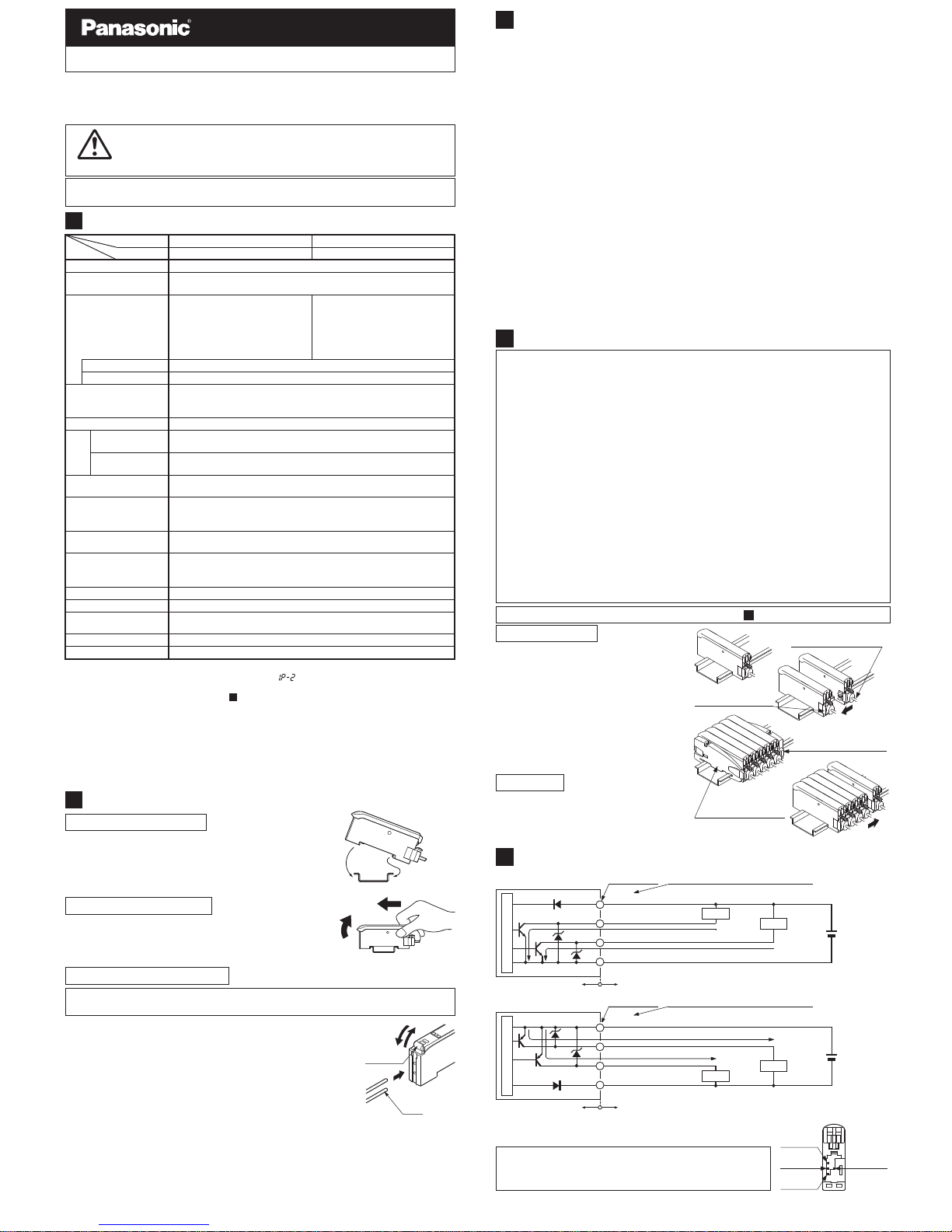
CASCADING
4
٨
٨
٨
٨
٨
٨
٨
٨
٨
Make sure that the power supply is off while adding or removing the amplifiers.
Make sure to check the allowable ambient temperature, as it depends on the
number of amplifiers connected in cascade.
In case two, or more, amplifiers are connected in cascade, make sure to mount them on a DIN rail.
When the amplifiers move on the DIN rail depending on the attaching condition or
the amplifiers are mounted close to each other in cascade, fit them between the
optional end plates (MS-DIN-E) mounted at the two ends.
When connecting amplifiers not close to each other in parallel, be sure to mount the optional end plate (MS-DIN-E) at both sides of each amplifier or affix the communication window
seal of the accessory amplifier protection seal (FX-MB1) to the communication window.
Up to maximum 15 amplifiers can be added (total 16 amplifiers connected in cascade.)
When connecting more than two amplifiers in cascade, use the sub cable (CN-72-Cغ)
as the quick-connection cable for the second amplifier onwards.
The settings other than the interference prevention function cannot be transmitted
between this product and other digital fiber amplifiers. Therefore, in case both models of amplifiers are mounted in cascade, be sure to mount identical models together. However, the interference prevention function is not incorporated in the
FX-301(P)-HS and FX-303(P). Take care when the sensors are mounted in cascade.
The communication function of this product and that of the FX-301(P)-F is different. If these models are mounted in cascade, affix the accessory amplifier protection seal (FX-MB1) to the communication windows of the amplifiers.
For mounting and removing the amplifier, refer to ' MOUNTING'.
2
Ԙ
ԙ
Ԛ
ԛ
Mount the amplifiers, one by one,
on the 35mm width DIN rail.
Slide the amplifiers next to each
other, and connect the quick-connection cables.
Mount the optional end plates
(MS-DIN-E)
at both the ends to hold
the amplifiers between their flat sides.
Tighten the screws to fix the end
plates.
Ԙ
ԙ
Ԛ
Loosen the screws of the end plates.
Remove the end plates.
Slide the amplifiers and remove
them one by one.
Cascading method
Dismantling
I/O CIRCUIT DIAGRAMS
5
٨
NPN output type
D1
50mA max. (Note 2)
50mA max. (Note 2)
ZD1
Tr1
Tr2
(Brown) +V (Note 1)
(Black) Output 1
(White) Output 2
+
12 to 24V DC
r10%
-
(Blue) 0V (Note 1)
1
2
3
4
Color code of quick-connection cable
Terminal No.
ZD2
Load
Load
Users' circuitInternal circuit
Sensor circuit
Color code of quick-connection cable
Terminal No.
+
12 to 24V DC
r10%
-
Load
50mA max. (Note 2)
50mA max. (Note 2)
(Brown) +V (Note 1)
(Black) Output 1
(White) Output 2
(Blue) 0V (Note 1)
D2
1
2
3
ZD3
Tr3
Tr4
ZD4
4
Load
Users' circuitInternal circuit
Sensor circuit
٨ PNP output type
Notes: 1)2)The quick-connection sub cable does not have +V (brown) and 0V
(blue). The power is supplied from the connector of the main cable.
25mA max. if five, or more, amplifiers are connected in cascade.
Symbols...D1, D2: Reverse supply polarity protection diode
Z
D1, ZD2, ZD3, ZD4: Surge absorption zener diode
T
r1, Tr2: NPN output transistor
T
r3, Tr4: PNP output transistor
Terminal arrangement
diagram
Ԙ +V
Ԛ
Output 1
ԛ
Output 2
ԙ 0V
SPECIFICATIONS
1
MOUNTING
2
ԘԙFit the rear part of the mounting section of the amplifier
on a 35mm width DIN rail.
Press down the rear part of the mounting section of the
unit on the 35mm width DIN rail and fit the front part of
the mounting section to the DIN rail.
How to mount the amplifier
Ԙ
35mm width DIN rail
ԙ
ԘԙPush the amplifier forward.
Lift up the front part of the amplifier to remove it.
Ԙ
ԙ
Take care that if the front part is lifted without pushing the
amplifier forward, the hook on the rear portion of the mounting section is likely to break.
Note:
How to remove the amplifier
Ԙ
ԙ
Ԛ
Snap the fiber lock lever down.
Insert the fiber cables slowly into the inlets until they stop. (Note 1)
Return the fiber lock lever to the original position, till it stops.
How to connect the fiber cables
Notes: 1)2)In case the fiber cables are not inserted to a position where they
stop, the sensing range reduces. In case of a flexible fiber, take
care that it may bend inside the amplifier, during insertion.
With the coaxial reflective type fiber, such as, FD-G4 or FD-FM2,
insert the single-core fiber cable into the beam-emitting inlet and
the multi-core fiber cable into the beam-receiving inlet. If they are
inserted in reverse, the sensing accuracy will deteriorate.
Ԙ
ԙ
Ԛ
Fiber
lock lever
Fiber
Be sure to fit the attachment to the fibers first before inserting the fibers to the
amplifier. For details, refer to the instruction manual enclosed with the fibers.
Notes: 1)
2)
3)
4)
50mA per output. 25mA if five, or more, amplifiers are connected in cascade.
When the interference prevention function ' ' is set, the number of mountable fibers
becomes double. Furthermore, take care that the response time also becomes double.
For the setting method, refer to ' PRO MODEPRO5 mode setting'.
When the power supply is switched on, the light emission timing is automatically set for
interference prevention.
The cable for amplifier connection is not supplied as an accessory. Make sure to use the
optional quick-connection cables given below.
Main cable (4-core): CN-74-C1 (cable length 1m), CN-74-C2 (cable length 2m)
CN-74-C5 (cable length 5m)
Sub cable (2-core):
CN-72-C1 (cable length 1m), CN-72-C2 (cable length 2m)
CN-72-C5 (cable length 5m)
13
Teaching (1-level / 2-level / 3-level) / Manual adjustment
Window comparator
mode
Sensitivity
setting
NPN open-collector transistor
Maximum sink current: each 50mA (Note 1)
Applied voltage: 30V DC or less
(between output and 0V)
Residual voltage: 1.5V or less
[at each 50mA (Note 1) sink current]
PNP open-collector transistor
Maximum source current: each 50mA (Note 1)
Applied voltage: 30V DC or less
(between output and +V)
Residual voltage: 1.5V or less
[at each 50mA (Note 1) source current]
Model No.
12 to 24V DCr10% Ripple P-P 10% or lessSupply voltage
Item FX-305PFX-305
PNP outputType NPN output
Power consumption
(Note 2)
Normal operation: 960mW or less (current consumption 40mA or less at 24V supply voltage)
ECO mode: 600mW or less (current consumption 25mA or less at 24V supply voltage)
Output
(Output 1, Output 2)
2-level teaching / Limit teaching / Full-auto teaching / Max. sensitivity teaching
/ Manual adjustment
Normal mode
H-SP: 65Ǵs or less, FAST: 150Ǵs or less, STD: 250Ǵs or less
STDF: 700Ǵs or less, LONG: 2.5ms or less, U-LG: 4.5ms or less
selectable with jog switch
Response time
4 digit red LED displayDisplay
Light-ON or Dark-ON, selectable with jog switchOutput operation
Incorporated
Short-circuit protection
Timer function
Incorporated with variable ON-delay / OFF-delay / ONE-SHOT / ONdelay
OFF-delay / ON-delayONE-SHOT timer, switchable either
effective or ineffective (Timer: approx. 0.5 to 9999ms)
Incorporated
Fine sensitivity
adjustment function
Interference prevention
function (Note 2) (Note 3)
Ambient temperature
-10 to +55 (If 4 to 7 units are connected in cascade: -10 to +50,
if 8 to 16 units are connected in cascade: -10 to +45)
(No dew condensation or icing allowed), Storage: -20 to +70
Red LED (modulated)Emitting element
Enclosure: Heat-resistant ABS, Transparent cover: Polycarbonate
Press switches: Acrylic, Jog switch: Heat-resistant ABS
Material
20g approx.Weight
35 to 85% RH, Storage: 35 to 85% RHAmbient humidity
Incorporated [up to four fibers can be mounted adjacently (However,
U-LG mode is eight fibers, H-SP mode is two fibers.)]
Accessory FX-MB1 (Amplifier protection seal): 1 set
Main cable (CN-74-Cغ)
(optional)
End plates (MS-DIN-E)
(optional)
End plates (MS-DIN-E)
(optional)
Sub cable (CN-72-Cغ)
(optional)
Slide
Slide
Thank you very much for purchasing Panasonic products. Please read this Instruction
Manual carefully and thoroughly for the correct and optimum use of this product.
Kindly keep this manual in a convenient place for quick reference.
INSTRUCTION MANUAL
Digital Fiber Sensor Amplifier FX-305(P)
MJE-FX305 No.0034-49V
Phone: 800.894.0412 - Fax: 888.723.4773 - Web: www.clrwtr.com - Email: info@clrwtr.com
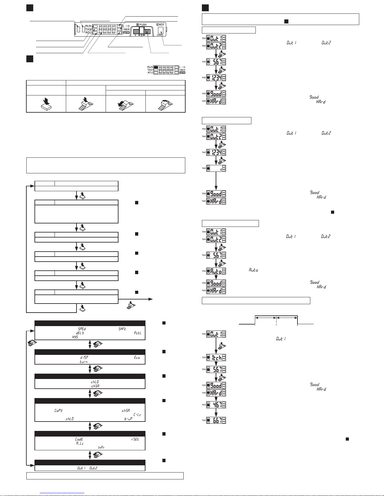
PART DESCRIPTION
6
MODE key
Jog switch
Digital display (Red)
MODE indicator /
PRO (Yellow)
MODE indicator / L/D ON (Yellow)
Output 1 operation indicator
(Orange)
MODE indicator / RUN (Green)
MODE indicator / ADJ (Yellow)
MODE indicator / TEACH (Yellow)
MODE indicator / TIMER (Yellow)
Output 2 operation
indicator (Orange)
OPERATION PROCEDURE
7
٨
When the power supply is switched on, communication self-check is carried out and normal condition is displayed [MODE indicator / RUN
(green)] lights up and the digital display shows the incident light intensity.
TEACHING MODE
8
In case of 2-level teaching
ԙ
Press Jog switch in the object present condition. If the
teaching is accepted, the read incident light intensity blinks in
the digital display. (Note 1)
Ԛ Press Jog switch in the object absent condition. (Note 1)
Press
Press
Press
Ԙ
Press MODE key to light up MODE indicator / TEACH (yellow).
Set to either Output 1 ' ' or Output 2 ' '.
Turn Jog switch: Select
Press Jog switch: Confirmed
ԛ
The threshold value is set at the mid-value between ԙ and Ԛ.
In case stable sensing is possible: '䇭䇭䇭䇭' is displayed.
In case stable sensing is not possible: '䇭䇭䇭䇭' is displayed.
Note:
In case of using the fibers, if Jog switch is pressed in the object absent condition at ԙ and Ԛ,
the sensitivity is set to the maximum.
Press
Press
Ԙ
Press MODE key to light up MODE indicator / TEACH (yellow).
Set to either Output 1 ' ' or Output 2 ' '.
Turn Jog switch: Select
Press Jog switch: Confirmed
ԛ In case stable sensing is possible: '䇭䇭䇭䇭' is displayed.
In case stable sensing is not possible: '䇭䇭䇭䇭' is displayed.
ԙ
Press Jog switch continuously for 0.5 sec. or more with the
object moving on the assembly line.
Ԛ
' ' is displayed on the digital display. Release the jog
switch when the object has passed.
In case of full-auto teaching
Press
Press
Ԙ
Press MODE key to light up MODE indicator / TEACH (yellow).
Set to Output 1 ' '.
Turn Jog switch: Select
Press Jog switch: Confirmed
ԛ In case stable sensing is possible: '䇭䇭䇭䇭' is displayed.
In case stable sensing is not possible: '䇭䇭䇭䇭' is displayed.
٨
This is the method of setting the threshold range by 1-level teaching. The shift
value can be set as desired.
In case of window comparator mode / 1-level teaching
1_SL P-1 2_SL
Set as
desired
Set as
desired
ԙ The current teaching method is displayed for 0.5 sec.
Ԛ Press Jog switch in the object present condition. If the
teaching is accepted, the read incident light intensity blinks in
the digital display.
Ԝ A value deducted the shift value (100) from the incident light
intensity becomes the threshold value (1_SL), which is
displayed. (Note 1) (Note 2)
ԝ A value added the shift value (100) to the incident light
intensity becomes the threshold value (2_SL), which is
displayed. (Note 1) (Note 2)
The shift value 100 digits is the initial value. The shift value can be changed in PRO mode.
Furthermore, 'digit' or 'percent' can be selected. For the setting method refer to ' PRO
MODEPRO6 mode setting'.
In case the set value exceeds the max. (min.) sensitivity, the set value is fixed at max.
(min.) sensitivity.
Notes: 1)
2)
13
In case of teaching in the window comparator mode, set the detailed settings in
PRO6 beforehand. For the settings, refer to ' PRO MODEPRO6 mode setting'.
13
In case of limit teaching
Press
Press
Ԙ
Press MODE key to light up MODE indicator / TEACH (yellow).
Set to either Output 1 ' ' or Output 2 ' '.
Turn Jog switch: Select
Press Jog switch: Confirmed
ԙ
Press Jog switch in the object absent condition. If the
teaching is accepted, the read incident light intensity blinks in
the digital display.
Ԛ Turn Jog switch to the '+' side or the '-' side.
If Jog switch is turned to '+' side, the threshold value level is shift
ed
to a value approx. 15% higher (lower sensitivity) than that set at Ԙ.
If Jog switch is turned to '-' side, the threshold value level is shifted
to a value approx. 15% lower (higher sensitivity) than that set at Ԙ
ԛ In case stable sensing is possible: '䇭䇭䇭䇭' is displayed.
In case stable sensing is not possible: '䇭䇭䇭䇭' is displayed.
The approx. 15% amount of shift is the initial value. The amount of shift can be changed in the
PRO mode from approx. 0 to 80% (5% step). For the setting method refer to ' PRO MODE
PRO1 mode setting'.
Note:
13
The 0-ADJ setting function in this product was removed from production starting May, 2005.
*1:
*2:
*3:
*4:
*5:
When Jog switch is pressed, the setting is confirmed.
When MODE key is pressed for 2 sec., or more, the sensor returns to the 'RUN' mode.
Cancellation is possible by pressing MODE key during setting.
When Jog switch is turned in the 'RUN' mode, the current threshold value is displayed.
And then, the current incident light intensity display appears again automatically.
If the jog switch and MODE key are pressed for more than 2 sec. at the same time in 'RUN'
mode condition, the key operations are locked, and only the threshold value confirmation
function or the adjust function (valid only when the adjust lock function is canceled) is valid.
To cancel the lock function, press both the keys for more than 2 sec. once again.
MODE key
Press Press
Turn
'+' side '-' side
Jog switch
٨ PRO mode
The items that can be set in output 1 and output 2 respectively are only the following.
The items other than those are common.
ԘThreshold value ԙOutput operation ԚTimer operation and Timer priod ԛDetection mode
٨ NAVI mode
This indicates normal sensing operation.
RunRUN
Refer to ' TEACHING MODE'.
8
Sets the threshold value by, '2-level teaching' or
'limit teaching', 'full-auto teaching', 'Max. sensitivity
teaching', 'Window comparator1-level / 2-level /
3-level teaching'.
TeachingTEACH
Refer to ' THRESHOLD VALUE FINE
ADJUSTMENT MODE'.
9
Allows fine adjustment of the threshold value.
AdjustADJ
Refer to ' OUTPUT OPERATION
SETTING MODE'.
11
Sets output operation either Light-ON, or Dark-ON.
L-ON/D-ONL/D ON
Refer to ' TIMER OPERATION
SETTING MODE'.
12
Configures operation of the timer.
TimerTIMER
Refer to ' PRO MODE'.
13
Allows various detailed settings to be configured, such
as optical communications, save/load and other settings.
ProPRO
Press
٨
To PRO mode
Press
Press
Press
Press
Press
Press
Refer to ' PRO
MODE PRO1
mode setting'.
13
Turn
Response time change function
''
Timer setting function ''
Hysteresis function ''
Shift function ''
Emitting power selection function
''
PRO1
Refer to ' PRO
MODE PRO2
mode setting'.
13
PRO2
Turn
Refer to ' PRO
MODE PRO3
mode setting'.
13
Refer to ' PRO
MODE PRO5
mode setting'.
13
Refer to ' PRO
MODE PRO4
mode setting'.
13
Setting condition copy
function ''
Remote data bank load
setting function ''
Remote data bank save
setting function ''
Communication lock function
''
Back-up function ''
PRO4
Turn
Turn
Turn
Turn
PRO3
Data bank load setting function ''
Data bank save setting function ''
Refer to ' PRO
MODE PRO6
mode setting'.
13
PRO5
Code setting function ''
Adjust lock setting function
''
Setting reset function ''
Interference prevention function
''
PRO6
Output setting function '', ''
ECO mode setting function ''
Digital display setting function ''
Digital display inversion function ''
Phone: 800.894.0412 - Fax: 888.723.4773 - Web: www.clrwtr.com - Email: info@clrwtr.com
 Loading...