

Page 1
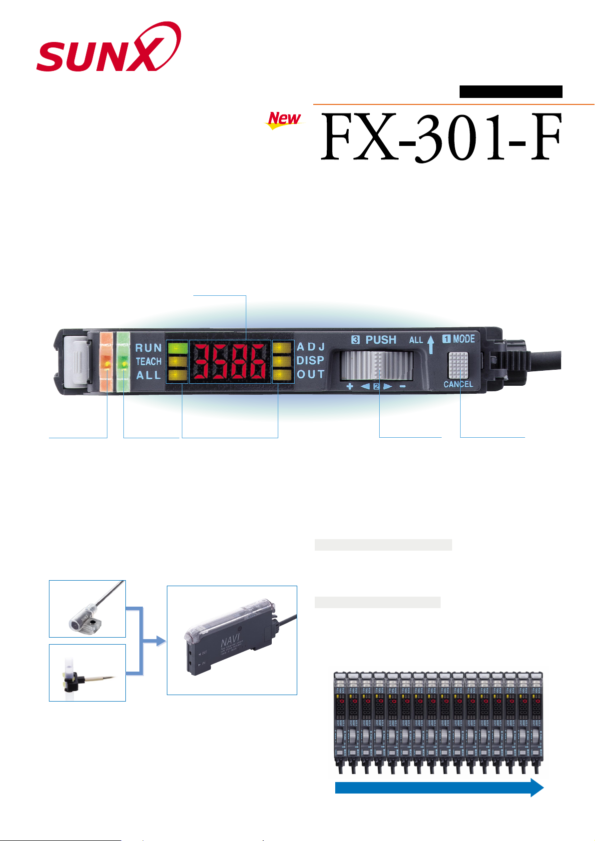
Operation indicator
●
●
Digital display
Large MODE key
●
Large jog switch
●
Model indicator
MODE indicators
DIGITAL FIBER SENSOR
Easy operation even for beginners
Optimum settings can be realized with simple operations.
Use Only with Leak or Liquid Fiber
For leak / liquid fibers only
FX-301-F is designed for use with only leak fiber, FD-F7 series or
liquid fiber, FT-F9 series. You can set the optimum conditions with
simple operations.
Easy to Operate with Individual / Collective Teaching Mode
Individual teaching mode (TEACH)
After you select FD-F7 series or FT-F9 series by the jog switch, the
optimum threshold level is automatically set by just pressing the jog
switch.
Collective teaching mode (ALL)
You can set the optimum sensitivity for all cascaded units in one step
by the optical communications function. Further, since the settings
are also copied to all the units, cumbersome setting operation is
considerably reduced.
Flashing Function Incorporated
When the leak fiber is connected (F7 mode), if a leak is detected, you
will recognize which fiber detects the leak at one sight because the
emitter will start flashing.
Long Life and No Adjustment Required with a Newly Developed LED
The new ‘LED using four chemical elements’ used in FX-301-F
minimizes light deterioration with time and enables stable detection
for a very long period.
Leak fiber,
FD-F7 series
Liquid fiber,
FT-F9 series
Leak fiber
FD-F7 series
Liquid fiber
FT-F9 series
FX-301-F
Quick-connection cable is optional.
Communication direction
Collective teaching mode is possible for 16 units max.
Page 2
SPECIFICATIONS
DIMENSIONS (Unit: mm)
I/O CIRCUIT DIAGRAMS
PRECAUTIONS FOR PROPER USE
Notes: 1)
50mA, if five, or more, amplifiers are connected in cascade.
2)
When detecting leak (output OFF) during leak setting (F7 mode), since the sensor flashes the emitted
light,only the response action for turning the signal back to ON is delayed (1 sec. approx.).
3) Please refer to FX-301 catalog or FIBER SENSOR GUIDE BOOK for the options.
1
Operation indicator (Orange) ··· Lights up when the output is ON.
2
Model indicator (Green) ··· Lights up during liquid setting (F9 mode).
3
MODE indicator ··· RUN (Green): Lights up during normal sensing operation.
TEACH (Yellow): Lights up when the individual teaching mode is selected.
ALL (Yellow): Lights up when the collective teaching mode is selected.
ADJ (Yellow):
Lights up when the threshold value fine adjustment mode is selected
or the sensitivity switching function is activated.
DISP (Yellow): Lights up when the digital display setting mode is selected or the
timer function is activated.
OUT (Yellow): Lights up when the forced output mode is selected or the NO/NC
switching function is activated.
4
Jog switch ··· Moving this switch in the ‘’ or ‘’ direction, allows different items to be viewed for
selection and pressing the switch then confirms the selected setting.
5
MODE key ···
This key is used to select operating modes and to cancel settings during the configuration process.
This product is not a safety sensor. Its use is not intended or designed
to protect life and prevent body injury or property damage from
dangerous parts of machinery. It is a normal object detection sensor.
Functional description
1
Operation indicator (Orange)
2
Model indicator (Green)
4
Jog switch
5
MODE key
3
MODE indicators
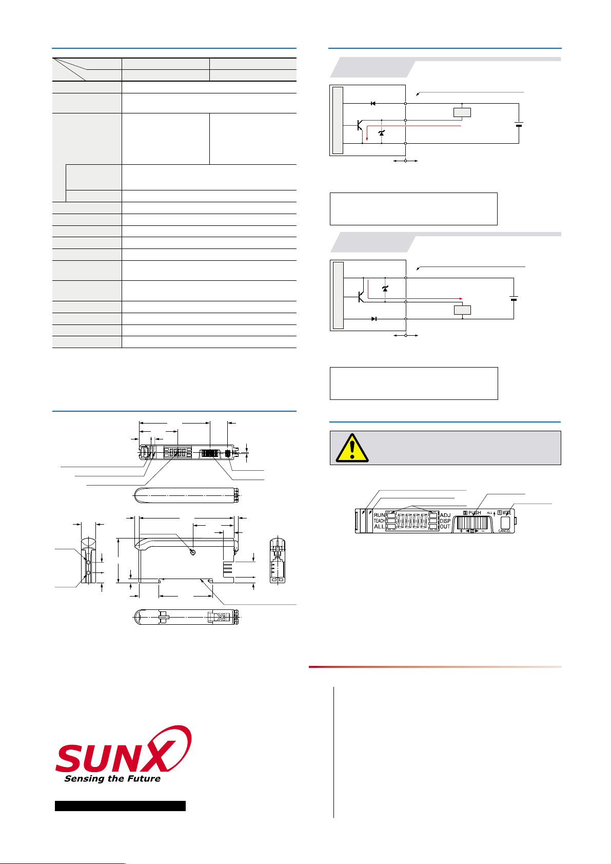
Notes: 1)
The quick-connection sub cable does not have V (brown) and 0V (blue).
2) 50mA max., if five amplifiers, or more, are connected in cascade.
3) Never connect several amplifiers in series (AND).
Symbols ...D:
Reverse supply polarity protection diode
ZD: Surge absorption zener diode
T
r: NPN output transistor
Symbols ...D:
Reverse supply polarity protection diode
ZD: Surge absorption zener diode
T
r: PNP output transistor
100mA max. (Note 2)
100mA max. (Note 2)
(Blue) 0V (Note 1)
(Blue) 0V (Note 1)
12 to 24V DC
10%
12 to 24V DC
10%
(Brown)
V (Note 1)
(Black) Output
(Black) Output
Color code of quick-connection cable
Users’ circuitInternal circuit
Tr
D
ZD
Sensor circuit
Load
0.7
48.2
12
26.3
2.58.3
MODE key
Jog switch
Digital display (Red)
Model indicator (Green)
Operation indicator (Orange)
27.8
7
10.5
3.95
36.513.5
364.53
30.5
3
Communication
window
Suitable for 35mm width DIN rail
7
7
10
Beamemitting
part
Beamreceiving
part
Item
250!s or less (Note 2)
Individual / collective teaching
12 to 24V DC
10% Ripple P-P 10% or less
Normal operation: 960mW or less (Current consumption 40mA or less at 24V supply voltage)
ECO mode: 600mW or less (Current consumption 25mA or less at 24V supply voltage)
NPN open-collector transistor
• Maximum sink current: 100mA (Note 1)
• Applied voltage: 30V DC or less
(between output and 0V)
• Residual voltage: 1.5V or less
[at 100mA (Note 1) sink current]
PNP open-collector transistor
• Maximum source current: 100mA (Note 1)
• Applied voltage: 30V DC or less
(between output and V)
•
Residual voltage: 1.5V or less
[at 100mA (Note 1) source current]
Incorporated
Leak setting (F7 mode): OFF with detection of leak
Liquid setting (F9 mode):
Using the jog switch, choose the signal
OFF condition between absence of liquid and presence of liquid.
Incorporated
Delay timer [used only for liquid setting (F9 mode)]
(Timer setting selectable from 10ms, 100ms, 1,000ms, and none)
Green LED [lights up during liquid setting (F9 mode)]
Orange LED (lights up when the output is ON)
0 to 50°C (If 8 to 16 units are connected in cascade: 0 to 45°C)
(No dew condensation), Storage:
20 to 70°C
Red LED (modulated)
Enclosure: Heat-resistant ABS, Case cover: Polycarbonate
20g approx.
Extension up to total 100m is possible with 0.3mm2, or more, cable.
FX-301-F
Output operation
Short-circuit protection
Supply voltage
Power consumption
Output
Response time
Operation indicator
Model indicator
Fine sensitivity adjustment function
Sensitivity setting
Timer function
Ambient temperature
Emitting element
Material
Cable extension
Weight
NPN output
FX-301P-F
PNP outputType
Model No.
No. LCE-FX301F-5 September, 2001
2431-1 Ushiyama-cho, Kasugai-shi, Aichi,
486-0901, Japan
Phone: +81-(0)568-33-7211
FAX: +81-(0)568-33-2631
SUNX Limited
Phone: +81-(0)568-33-7861
FAX: +81-(0)568-33-8591
Overseas Sales Dept.
Printed on 100% recycled paper PRINTED IN JAPAN
http://www.sunx.co.jp/
All information is subject to change without prior notice.
FX-301-F
NPN output
FX-301P-F
PNP output
Notes: 1)
The quick-connection sub cable does not have V (brown) and 0V (blue).
2) 50mA max., if five amplifiers, or more, are connected
in cascade
.
3) Never connect several amplifiers in series (AND).
Color code of quick-connection cable
(Brown)
V (Note 1)
Users’ circuitInternal circuit
D
ZD
Tr
Sensor circuit
Load
 Loading...