

Page 1
FX-301
08/2005
Digital Fiber Sensor
http://www.fiber-sensor.com
* UL 61010C-1 compatible, Passed the UL 991 Environment Test based on SEMI S2-0200.
[Category applicable for semiconductor manufacturing: TWW2, Process Equipment]
[Applicable standards: UL 61010C-1]
[Additional test / evaluation standards as per intended use: UL 991, SEMI S2-0200]
SERIES
Superior performance and
advanced user-friendly
multi-functionality
enables expert usage on
the very first day
* Passed the UL 991 Environment Test
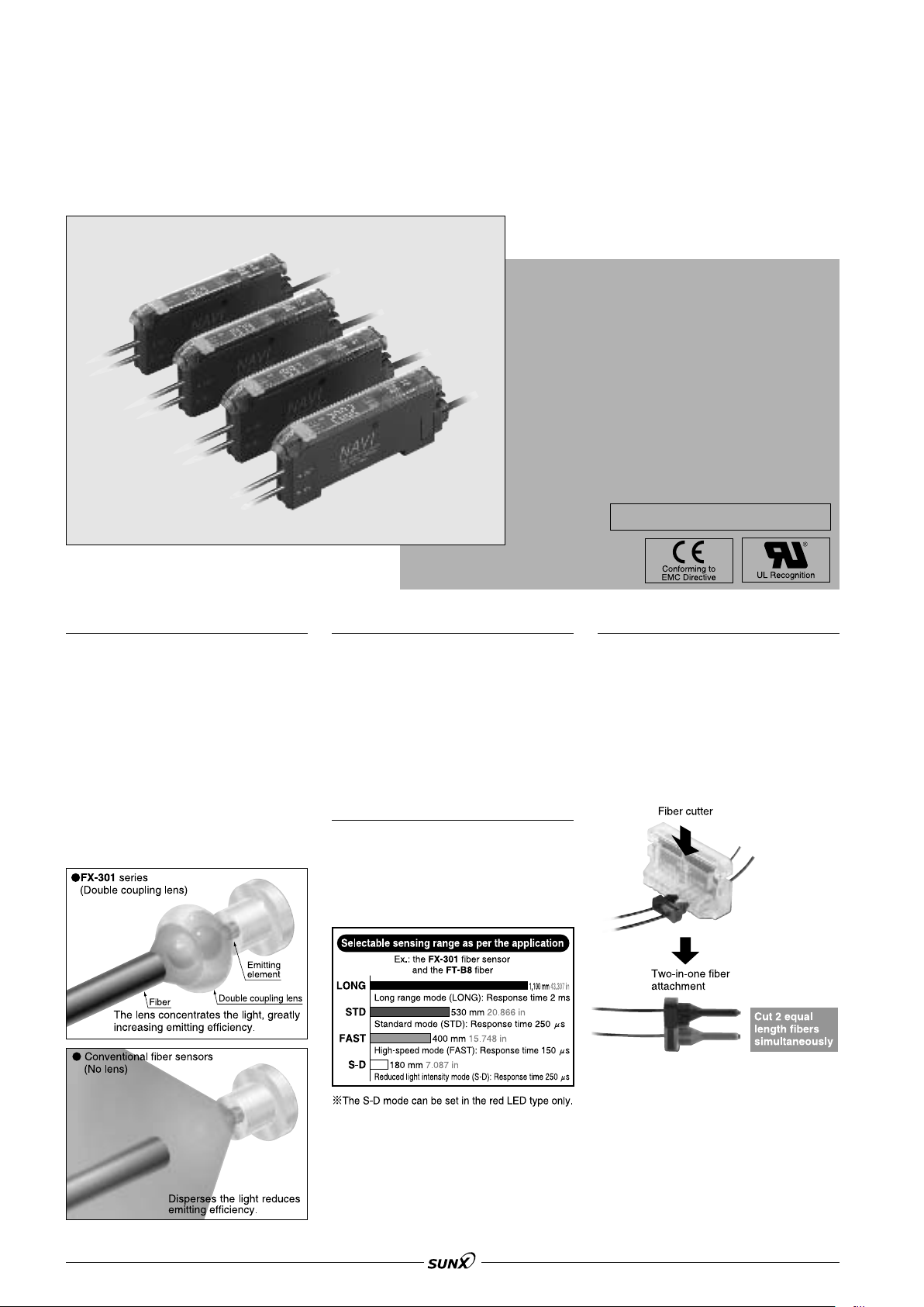
Long-range sensing made possible with built-in optical lens
For the first time in the industry, an
optical ‘double coupling lens’ has been
incorporated directly into the fiber
sensor itself. This lens maximizes the
light emission efficiency, resulting in a
tremendous improvement in the
sensing range. Sensing ranges with
small diameter fibers and ultra-small
diameter fibers, which have become
very popular in recent years due to the
miniaturization of chip components,
have been increased by 50 % over
previous values achieved with other
amplifiers.
Stable long-term sensing
The newly developed four-chemical
emitting element that uses the FX-301
(red LED type) suppresses changes
over long periods of time as much as
possible, so that a stable light emitting
level is maintained. There is very little
element deterioration so that stable
and accurate sensing can be
maintained over long periods.
Selectable response time
We offer 4 selectable levels to
correspond with various applications:
the response time 150 !s FAST mode,
the LONG mode, perfect for adverse
environments, and the S-D mode,
especially made for minute detection.
Enhanced worksite-friendly installability
Our new fiber cutter utilizes a specially
developed two-in-one fiber attachment
that now makes it possible to cut two
fibers simultaneously to exactly the
same length. Also, since the fibers can
be attached to the amplifier while
being fixed in position in the two-in-one
fiber attachment, sensitivity changes
due to variation in the amount of fiber
insertion do not occur.
68
Page 2
FX-301
08/2005
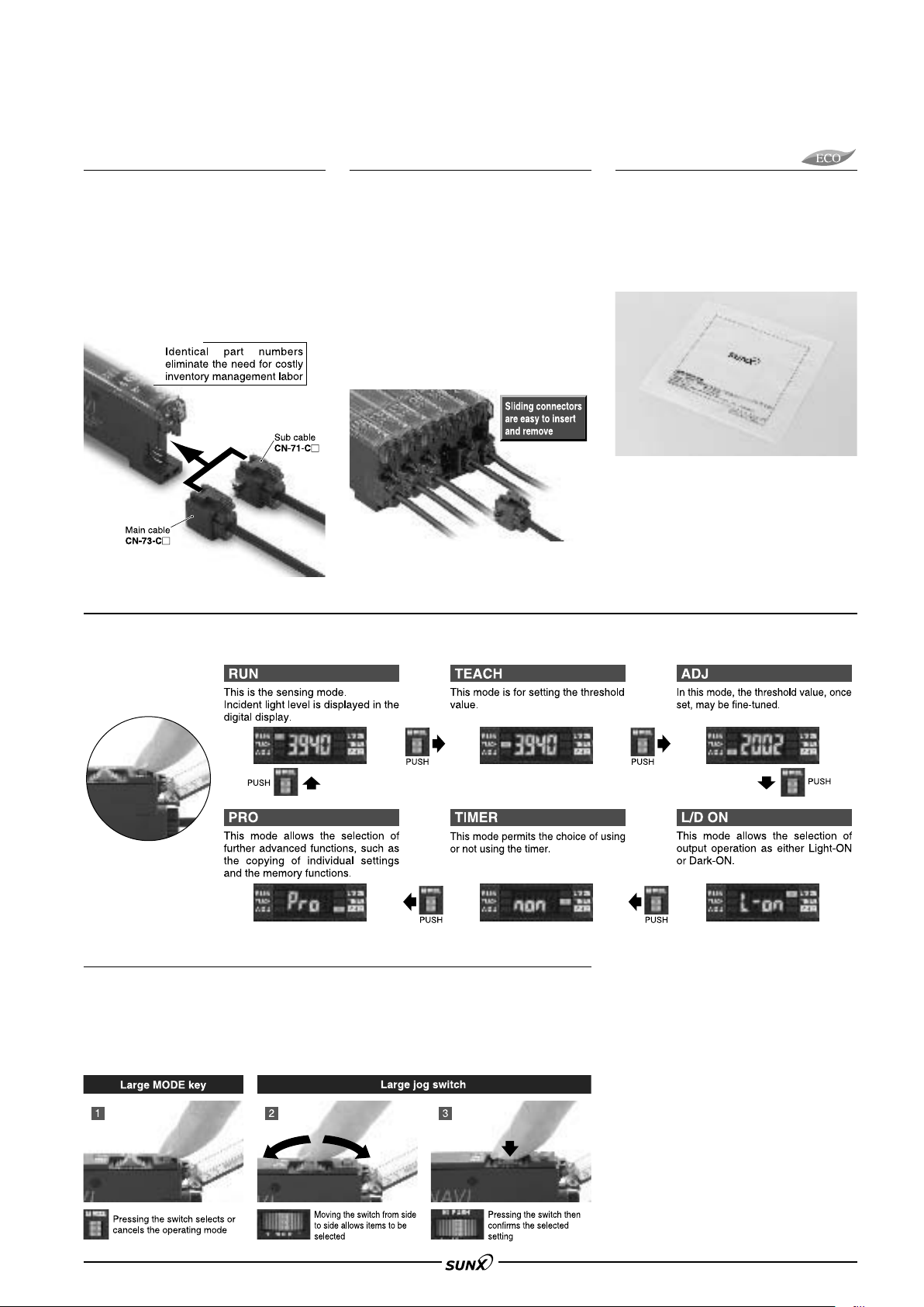
Easy maintenance, as main
and sub units are identical
Both main and sub units utilize the same
amplifier body. This feature allows for
easy mounting in the side-by-side
configuration. The main and sub unit
functions are distinguished only by the
proper use of 3-core main cable and the
1-core sub cable. Moreover, by utilizing
the same body for both main and sub
units, inventory management and
maintenance is simplified.
Wiring- and labor-saving design allows sideby-side configuration for up to sixteen units
Up to sixteen amplifiers can be
connected in a side-by-side configuration.
As the sub cable contains only one output
line, a great amount of wiring and space
can be saved. Also, special ‘sliding’
connectors have been provided for all
main and sub cables, which can be
detached merely by releasing the lock
and pulling directly back, without having
to slide the amplifier body to the side.
Using this connector system, only a
minimal amount of space is required for
regular maintenance.
Environmentally friendly packaging
With regard to effects on the environment,
we only utilize the simplest of packaging
methods greatly contributing to the reduction
in wastes generated by your worksite.
Also, the bags are made of polyethylene, a
substance that doesn’t give off polluting
gases when burned.
Polyethylene packaging
Even beginners can quickly learn how to use the MODE NAVI
MODE NAVI uses six indicators to display the amplifier’s basic operations. The current operating mode can be confirmed at a
glance, so even a first time user can easily operate the amplifier without becoming confused.
The use of only two switches makes for very simple operations
Only two switches, the large jog switch and the large MODE key, are required for
operation. Depressing the large MODE key sets the ‘mode selection’ and ‘mode
cancel’ functions. The large jog switch is used to select from the detailed functions
available within each mode, as well as to change numerical values after the mode
has been chosen.
69
Page 3
FX-301
08/2005
4 types of light sources available
In addition to our red LED (four-chemical
emitting element) type, the blue, green,
and infrared LED types are also provided
to correspond to your specific application.
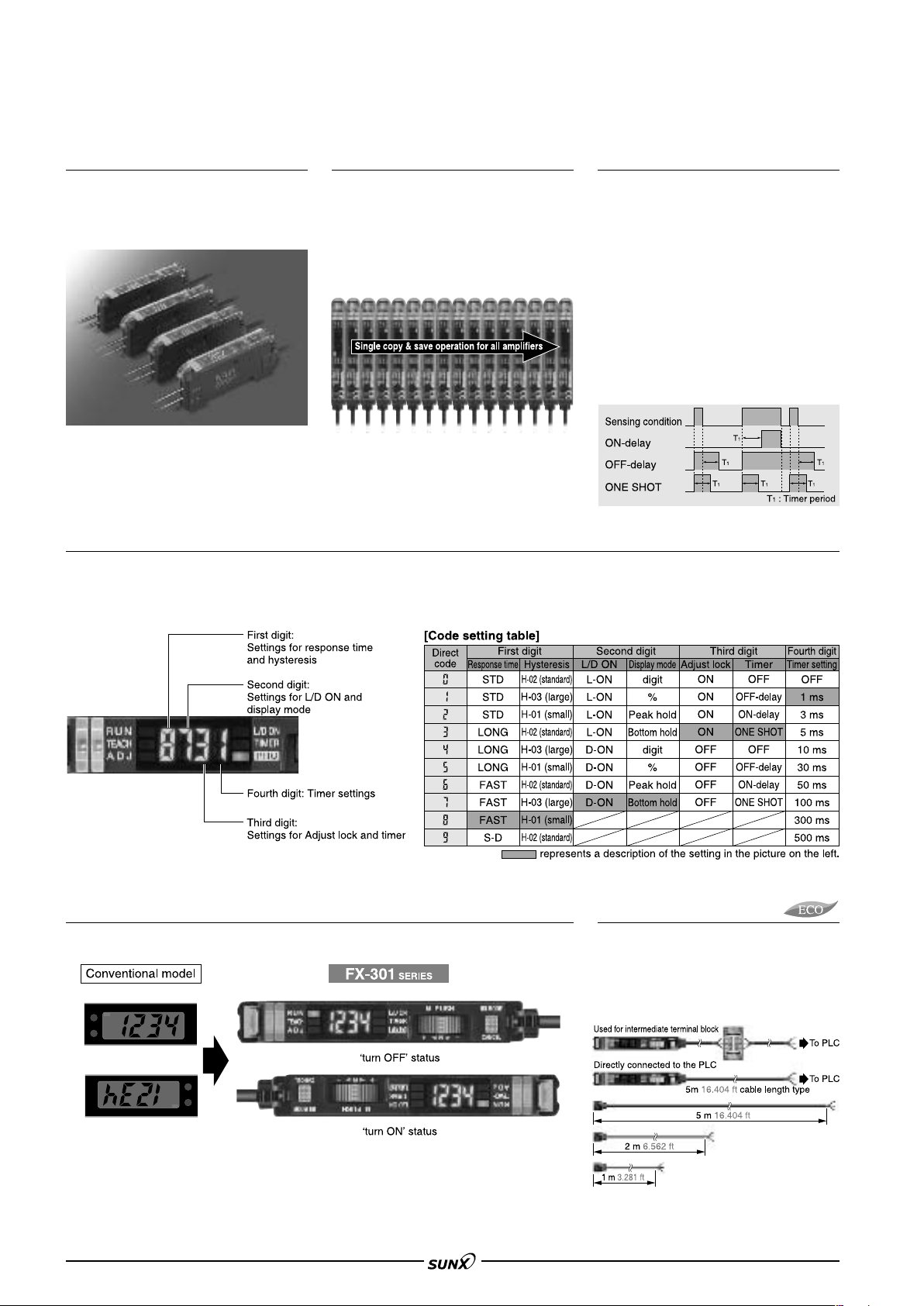
Optical communication function lets
multiple sensors be adjusted all at once
The optical communication function
allows the data that is currently set to
be copied and saved all at once for all
amplifiers connected together from the
right side. This greatly reduces
troublesome setup tasks and makes
setup much smoother.
Equipped with each type of timer
These sensors are equipped with 3
types of timers, ON-delay, OFF-delay,
and ONE SHOT, for compatibility to
variegated environments.
ON-delay timer
This function is useful for sensing only
objects taking a long time travel.
OFF-delay timer
This function is useful when the
connected device has a slow response
time.
ONE SHOT timer
This function is useful when the input
specifications of the connected device
require a signal of fixed width.
Easy code input setting
Every function can be directly set merely by the input of a four digit code (numbers) from the code table. This convenient
feature is easy to set up.
In the event that settings are accidentally changed at the operating site, merely entering the correct code can restore the
original settings. This results in easy and quick maintenance.
Invertible digital display
The digital display can be inverted as per its orientation once mounted onto the amplifier.
Selectable cable length
Made available are 3 lengths, 1 m 3.281 ft,
2 m 6.562 ft, and 5 m 16.404 ft, to suit
your application requirements. This helps
reduce the waste caused by cutting cables
and lightens the installation workload.
70
Page 4
FX-301
08/2005
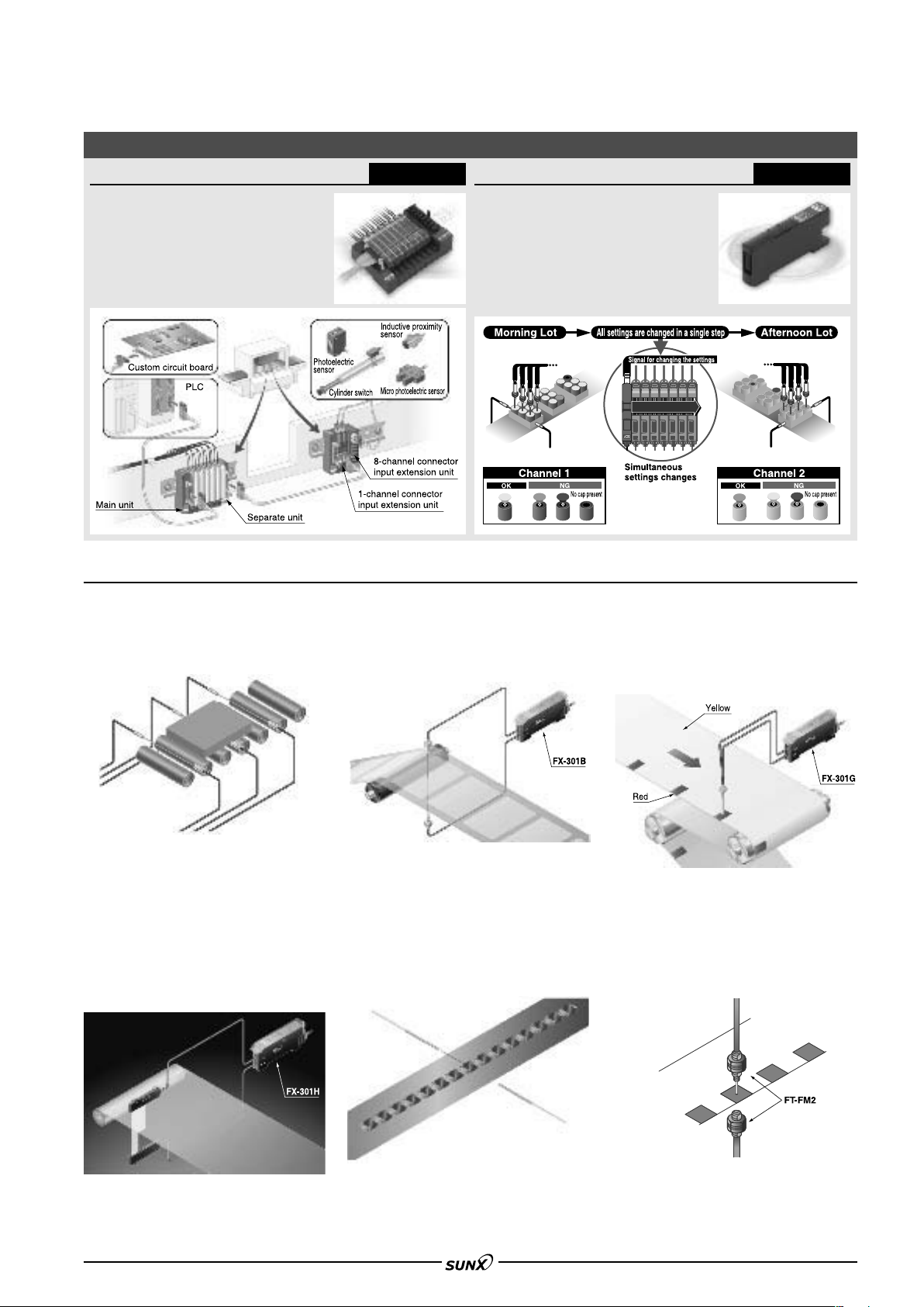
Optional units for greater freedom and control when installing
Sensor-PLC connection system
This wire-saving system enables the
collective connection of up to 16 I/O
devices with an MIL connector.
Scattered installation is also possible
with the help of a sensor separate
unit.
APPLICATIONS
Workpieces detection
This standard type of FX-301 using red light
has a four-chemical emitting element for
stable sensing over long periods.
SC
SERIES
Bank selection unit
Without directly manipulating the
sensor itself, you can simultaneously
switch up to 16 fiber sensors’ settings
using an external emitted signal.
(Load and save)
mAlso possible with the FX-301 series’ databank
function
Sensing semi-transparent stickers
The blue LED type greatly reduces the
dampening rate, making it ideal for delicate
sensing.
FX-CH
SERIES
Sensing register marks
The green LED type can accurately
discriminate between red and yellow, that
cannot be easily detected using red LED
type.
Sensing film meandering
Infrared LED type is ideal for sensing
environments with light restrictions, such as
places where light-sensitive film is being
handled. (The emission peak wavelength:
940 nm 0.037 mil.) It includes full-auto
teaching function which allows sensitivity to
be set without stopping the workpiece line.
Detecting chip component
Because of low light intensity fluctuations
when detecting minute moving objects,
decrease the hysteresis in PRO mode and
accurate sensing will be possible in highspeed mode. This method is optimal for chip
component verification in taping equipment.
Detecting register marks on a
transparent sheet
When detecting registration marks on
transparent film with a thru-beam type, the
S-D (reduced light intensity) mode will
enable minute light intensity fluctuation
sensing.
71
Page 5
FX-301
08/2005
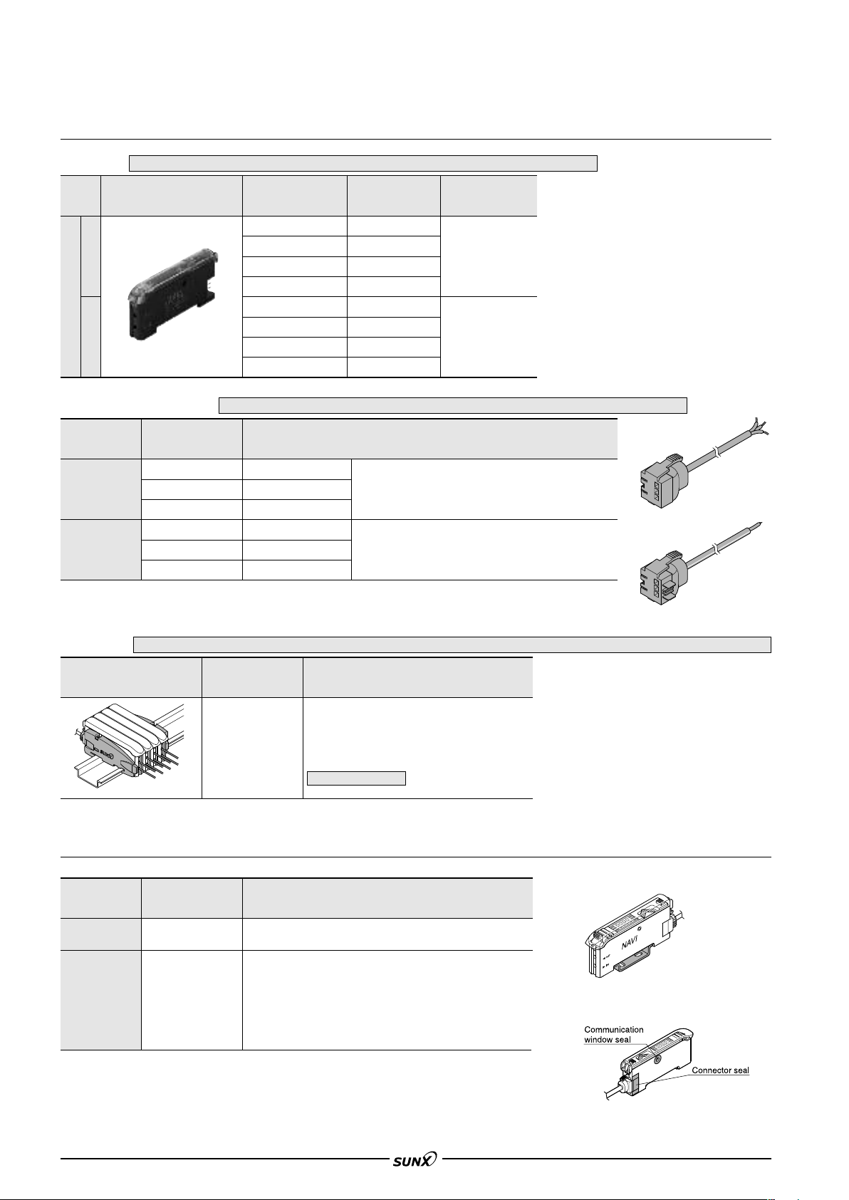
ORDER GUIDE
Amplifiers
Quick-connection cable is not supplied with the amplifier. Please order it separately.
Type Appearance Model No. Emitting element Output
Red LED
Blue LED
Green LED
Infrared LED
Red LED
Blue LED
Green LED
Infrared LED
NPN open-collector
transistor
PNP open-collector
transistor
NPN output
Digital
PNP output
Quick-connection cables
FX-301
FX-301B
FX-301G
FX-301H
FX-301P
FX-301BP
FX-301GP
FX-301HP
Quick-connection cable is not supplied with the amplifier. Please order it separately.
Type Model No. Description
Length: 1 m 3.281 ft
Length: 2 m 6.562 ft
Length: 5 m 16.404 ft
Length: 1 m 3.281 ft
Length: 2 m 6.562 ft
Length: 5 m 16.404 ft
2
0.15 mm
Cable outer diameter: "3.0 mm "0.118 in
0.15 mm
Cable outer diameter: "3.0 mm "0.118 in
3-core cabtyre cable, with connector on one end
2
1-core cabtyre cable, with connector on one end
Main cable
Sub cable
CN-73-C1
CN-73-C2
CN-73-C5
CN-71-C1
CN-71-C2
CN-71-C5
Main cable
• CN-73-C
Sub cable
• CN-71-C
End plates
End plates are not supplied with the amplifier. Please order separately when the amplifiers are mounted in cascade.
Appearance Model No. Description
When cascading multiple amplifiers, or when it
moves depending on the way it is installed on a
MS-DIN-E
DIN rail, these end plates ensure that all
amplifiers are mounted together in a secure and
fully connected manner.
Two pcs. per set
OPTIONS
Designation Model No. Description
Amplifier mounting
bracket
Fiber amplifier
protective seal
MS-DIN-2
FX-MB1
Mounting bracket for amplifier
10 sets of 2 communication window seals and 1 connector seal
Communication window seal:
It prevents malfunction due to transmission signal from another
amplifier, as well as, prevents effect on another amplifier.
Connector seal:
It prevents contact of any metal, etc., with the pins of the quickconnection cable.
Amplifier mounting bracket
• MS-DIN-2
Fiber amplifier protective seal
• FX-MB1
72
Page 6
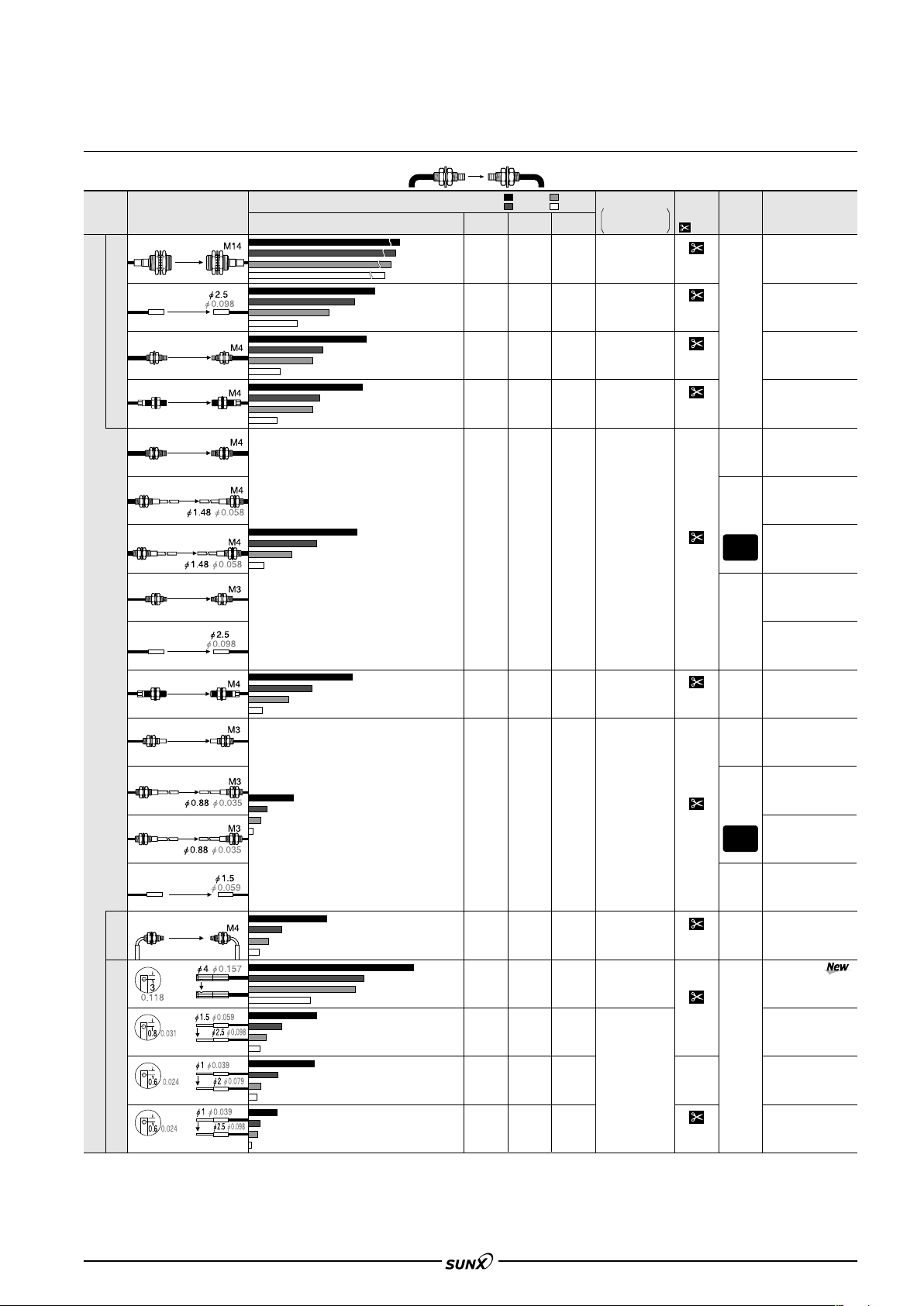
LIST OF FIBERS
08/2005
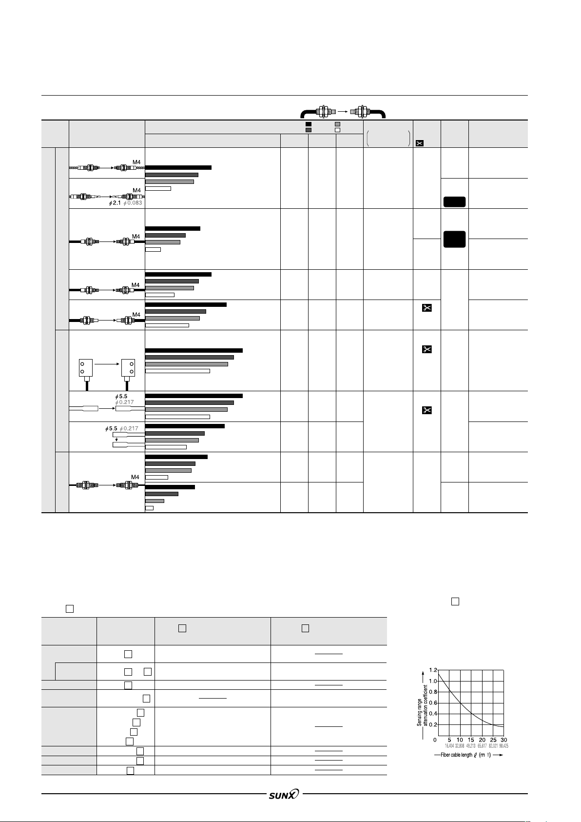
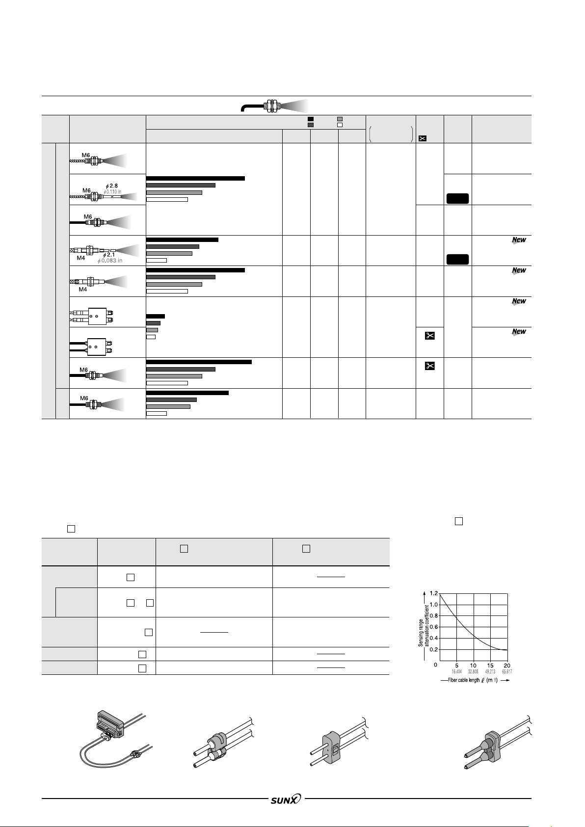
Standard fibers [Thru-beam type (one pair set)]
Shape of fiber head
Type
With lens
With lens
Lens mountable
Long sensing range
Lens mountable
Sleeve 90 mm 3.543 in
Sleeve 40 mm 1.575 in
Lens mountable
(mm in)
Sensing range (mm in ) (Note 1)
Red LED
1,600 62.992
800 31.496
580 22.835
280 11.024
180 7.087
168 6.614
280 11.024
130 5.118
400 15.748
360 14.173
400 15.748
530 20.866
480 18.898
780 30.709
1,100 43.307
1,000 39.370
19,500 767,715
14,000 551.180
10,000 393.700
3,800 149.606
Blue LED
5,400
212.598
2,700
106.299
1,900 74.803
400 15.748
200 7.874
130 5.118
220 8.661
110 4.331
75 2.953
200 7.874
100 3.937
70 2.756
150 5.906
75 2.953
40 1.575
:LONG
:STD
Green LED
Infrared LED
2.400
2,800
110.236
1,200 47.244
1,400 55.118
1,000 39.370
200 7.874
100 3.937
65 2.559
110 4.331
55 2.165
40 1.575
100 3.937
50 1.969
35 1.378
70 2.756
35 1.378
24 0.945
900 35.433
(Note 3)
155 6.102
100 3.937
:FAST
Min. sensing object
:S-D
under the optimum
condition (Note 2)
94.488
"0.4 mm
"0.016 in
opaque object
"0.02 mm
77 3.031
"0.0008 in
55 2.165
opaque object
"0.04 mm
50 1.969
"0.0016 in
30 1.181
opaque object
90 3.543
"0.03 mm
45 1.772
"0.0012 in
28 1.102
opaque object
50 1.969
"0.03 mm
25 0.984
"0.0012 in
18 0.709
opaque object
FX-301
Allowable
Fiber cable
bending
length
:
Free-cut
10 m
32.808 ft
2 m
6.562 ft
2 m
6.562 ft
2 m 6.562 ft
(Note 4)
2 m
6.562 ft
radius
R25 mm
R0.984 in
R25 mm
R0.984 in
Fiber
R25 mm
R0.984 in
Sleeve
R10 mm
R0.394 in
R25 mm
R0.984 in
Model No.
FT-FM10L
FT-SFM2L
FT-B8
FT-NB8
FT-FM2
FT-FM2S
FT-FM2S4
FT-T80
FT-SFM2
700 27.559
360 14.173
250 9.843
Standard
Sleeve 90 mm 3.543 in
Sleeve 40 mm 1.575 in
Lens mountable
Elbow
Sleeve part cannot be bent.
Side-view
Sleeve part cannot be bent.
Sleeve part cannot be bent.
Notes: 1)
Notes: 2) The minimum sensing object size is the value for red LED type. Please contact our office for information on the minimum sensing object size if using
Notes: 3) Sensing range for a 2 m 6.562 ft long fiber. A 10 m 32.808 ft long fiber will cause damping of the beam and cannot be used.
Notes: 4) The fiber cutter is not supplied as an accessor y with FT-NB8 and FT-N8. Please order it separately.
Please take care that the sensing range of the free-cut type fiber may be reduced by 20 % max. depending upon how the fiber is cut. In addition, the infrared
type is easily affected by humidity, so contact our office if using these sensors in environments with high humidity or where humidity levels can fluctuate.
amplifiers other than red LED type.
The optimum condition is the condition when the sensitivity is set so that the sensing output just changes to light incident operation in the object absent
condition.
126 4.961
140 5.512
100 3.937
49 1.929
150 5.906
80 3.150
140 5.512
70 2.756
180 7.087
125 4.921
63 2.480
175 6.890
80 3.150
60 2.362
27 1.063
270 10.630
230 9.055
350 13.780
400 15.748
200 7.874
390 15.354
530 20.866
1,000 39.370
800 31.496
2,000 78.740
140 5.512
70 2.756
40 1.575
50 1.969
25 0.984
16 0.630
85 3.346
42 1.654
28 1.102
400 15.748
200 7.874
130 5.118
80 3.150
40 1.575
28 1.102
50 1.969
25 0.984
16 0.630
28 1.102
14 0.551
10 0.394
200 7.874
100 3.937
66 2.598
33 1.299
22 0.866
24 0.945
12 0.472
8 0.315
44 1.732
22 0.866
16 0.630
65 2.559
40 1.575
20 0.787
14 0.551
26 1.024
13 0.512
8 0.315
14 0.551
7 0.276
5 0.197
45 1.772
22 0.866
17 0.669
16 0.630
8 0.315
5 0.197
32 1.260
16 0.630
12 0.472
150 5.906
75 2.953
40 1.575
30 1.181
15 0.591
12 0.472
44 1.732
22 0.866
15 0.591
10 0.394
5 0.197
3 0.118
"0.03 mm
"0.0012 in
opaque object
"0.025 mm
"0.0010 in
opaque object
"0.04 mm
"0.0016 in
opaque object
"0.05 mm
"0.0019 in
opaque object
"0.02 mm
"0.0008 in
opaque object
2 m 6.562 ft
(Note 4)
2 m
6.562 ft
2 m
6.562 ft
2 m
6.562 ft
1 m
3.281 ft
2 m
6.562 ft
R25 mm
R0.984 in
R25 mm
R0.984 in
Fiber
R25 mm
R0.984 in
Sleeve
R10 mm
R0.394 in
R25 mm
R0.984 in
R25 mm
R0.984
in
R25 mm
R0.984 in
FT-N8
FT-NFM2
FT-NFM2S
FT-NFM2S4
FT-SNFM2
FT-R80
FT-V10
FT-SFM2SV2
FT-V22
FT-V41
73
Page 7
FX-301
08/2005
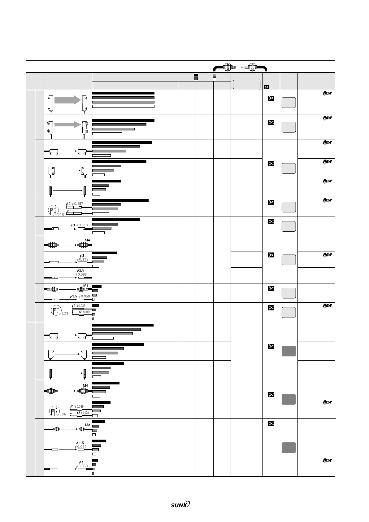
LIST OF FIBERS
Sharp bending fibers / Flexible fibers [Thru-beam type (one pair set)]
700 27.559
600 23.622
300 11.811
220 8.661
400 15.748
200 7.874
140 5.512
240 9.449
120 4.724
80 3.150
80 3.150
40 1.575
25 0.984
300 11.811
150 5.906
100 3.937
240 9.449
120 4.724
90 3.543
90 3.543
45 1.772
30 1.181
16 0.630
8 0.315
5 0.197
560 22.047
280 11.024
200 7.874
400 15.748
200 7.874
140 5.512
120 4.724
60 2.362
40 1.575
130 5.118
65 2.559
45 1.772
50 1.969
25 0.984
18 0.709
32 1.260
16 0.630
12 0.472
36 1.417
18 0.709
14 0.551
14 0.551
7 0.276
4 0.157
:LONG
:STD
Green LED
1,200 47.244
600 23.622
350 13.780
300 11.811
150 5.906
110 4.331
200 7.874
100 3.937
70 2.756
120 4.724
60 2.362
40 1.575
40 1.575
20 0.787
13 0.512
160 6.299
80 3.150
60 2.362
120 4.724
60 2.362
40 1.575
56 2.205
28 1.102
20 0.787
10 0.394
5 0.197
3 0.118
200 7.874
100 3.937
65 2.559
200 7.874
100 3.937
65 2.559
60 2.362
30 1.181
22 0.866
70 2.756
35 1.378
25 0.984
26 1.024
13 0.512
8 0.315
18 0.709
9 0.354
7 0.276
20 0.787
10 0.394
8 0.315
6 0.236
3 0.118
2 0.079
Shape of fiber head
Type
Wide beam
Rectangular head
Narrow beam
Sharp bending
Long sensing range
Standard
Small diameter
Side-view
Rectangular head
Flexible
Standard
Small diameter
Notes: 1)
Notes: 2)
Notes: 3) The fiber cable length practically limits the sensing range to 3,500 mm 137.795 in long.
(mm in)
Wide area sensing
Sensing width
32 mm
1.260 in
W5H69D20
W0.197H2.717D0.787
Wide area sensing
Sensing width
11 mm
0.433 in
W4.2H31D13.5
W0.165H1.220D0.531
Easy mounting Top sensing
W3H8D12 W0.118H0.315D0.472
Easy mounting Side sensing
W3H12D8 W0.118H0.472D0.315
Easy mounting Front sensing
W8.5H12D3 W0.335H0.472D0.118
Side-view type with small light
dispersion
With lens Long sensing range
Lens mountable
Sleeve part cannot be bent.
Easy mounting
W3H8D12 W0.118H0.315D0.472
Easy mounting Side sensing
W3H12D8 W0.118H0.472D0.315
Easy mounting
W8.5H12D3 W0.335H0.472D0.118
Lens mountable
Lens mountable
Please take care that the sensing range of the free-cut type fiber may be reduced by 20 % max. depending upon how the fiber is cut. In addition, the infrared
type is easily affected by humidity, so contact our office if using these sensors in environments with high humidity or where humidity levels can fluctuate.
The minimum sensing object size is the value for red LED type. Please contact our office for information on the minimum sensing object size if using amplifiers other than red LED
type. The optimum condition is the condition when the sensitivity is set so that the sensing output just changes to light incident operation in the object absent co
Top sensing
Front sensing
Sensing range (mm in) (Note 1)
Red LED
1,100 43.307
750 29.528
1,200 47.244
850 33.465
410 16.142
700 27.559
500 19.685
210 8.268
700 27.559
330 12.992
240 9.449
120 4.724
700 27.559
600 23.622
210 8.268
200 7.874
100 3.937
160 6.299
80 3.150
55 2.165
28 1.102
90 3.543
40 1.575
30 1.181
15 0.591
280 11.024
140 5.512
230 9.055
110 4.331
190 7.480
140 5.512
80 3.150
250 9.843
100 3.937
75 2.953
35 1.378
280 11.024
120 4.724
90 3.543
42 1.654
80 3.150
40 1.575
30 1.181
17 0.669
300 11.811
600 23.622
420 16.535
570 22.441
290 11.417
490 19.291
600 23.622
400 15.748
300 11.811
650 25.591
320 12.598
400 15.748
1,000 39.370
800 31.496
800 31.496
1,200 47.244
1,400 55.118
1,600 62.992
3,500 137.795
3,500 137.795
3,500 137.795
3,500 137.795
(Note 3)
3,500 137.795
1,500 59.055
2,500 98.425
1,500 59.055
1,700 66.929
2,700 106.299
Blue LED
2,400 94.488
1,200 47.244
:FAST
:S-D
Infrared LED
800 31.496
400 15.748
240 9.449
220 8.661
110 4.331
80 3.150
180 7.087
90 3.543
65 2.559
100 3.937
50 1.969
30 1.181
36 1.417
18 0.709
12 0.472
150 5.906
75 2.953
45 1.772
110 4.331
55 2.165
35 1.378
42 1.654
21 0.827
15 0.591
8 0.315
4 0.157
2.5 0.098
180 7.087
90 3.543
65 2.559
140 5.512
70 2.756
50 1.969
46 1.811
23 0.906
16 0.630
56 2.205
28 1.102
20 0.787
20 0.787
10 0.394
7 0.276
14 0.551
7 0.276
5 0.197
18 0.709
9 0.354
7 0.276
14 0.551
7 0.276
4 0.157
Min. sensing object
under the optimum
condition (Note 2)
"0.3 mm
"0.012 in
opaque object
"0.25 mm
"0.010 in
opaque object
"0.08 mm
"0.003 in
opaque object
"0.05 mm
"0.0020 in
opaque object
"0.04 mm
"0.0016 in
opaque object
"0.06 mm
"0.0024 in
opaque object
"0.02 mm
"0.0008 in
opaque object
"0.03 mm
"0.0012 in
opaque object
"0.05 mm
"0.0020 in
opaque object
"0.03 mm
"0.0012 in
opaque object
"0.02 mm
"0.0008 in
opaque object
"0.02 mm
"0.0008 in
opaque object
"0.03 mm
"0.0012 in
opaque object
"0.04 mm
"0.0016 in
opaque object
"0.02 mm
"0.0008 in
opaque object
Fiber cable
length
:
Free-cut
2 m
6.562 ft
2 m
6.562 ft
2 m
6.562 ft
2 m
6.562 ft
2 m
6.562 ft
2 m
6.562 ft
2 m
6.562 ft
2 m
6.562 ft
2 m
6.562 ft
2 m
6.562 ft
2 m
6.562 ft
1 m
3.281 ft
500 mm
19.685 in
Allowable
bending
radius
R1 mm
R0.039 in
R1 mm
R0.039 in
R1 mm
R0.039 in
R1 mm
R0.039 in
R1 mm
R0.039 in
R1 mm
R0.039 in
R1 mm
R0.039 in
R1 mm
R0.039 in
R4 mm
R0.157 in
R4 mm
R0.157 in
R4 mm
R0.157 in
Model No.
FT-WA30
FT-WA8
FT-WZ8H
FT-WZ8E
FT-WZ8
FT-WKV8
FT-WS8L
FT-W8
FT-WS3
FT-WS8
FT-W4
FT-WS4
FT-WV42
FT-Z8H
FT-Z8E
FT-Z8
FT-P80
FT-P60
FT-P40
FT-P2
FT-PS1
ndition.
74
Page 8
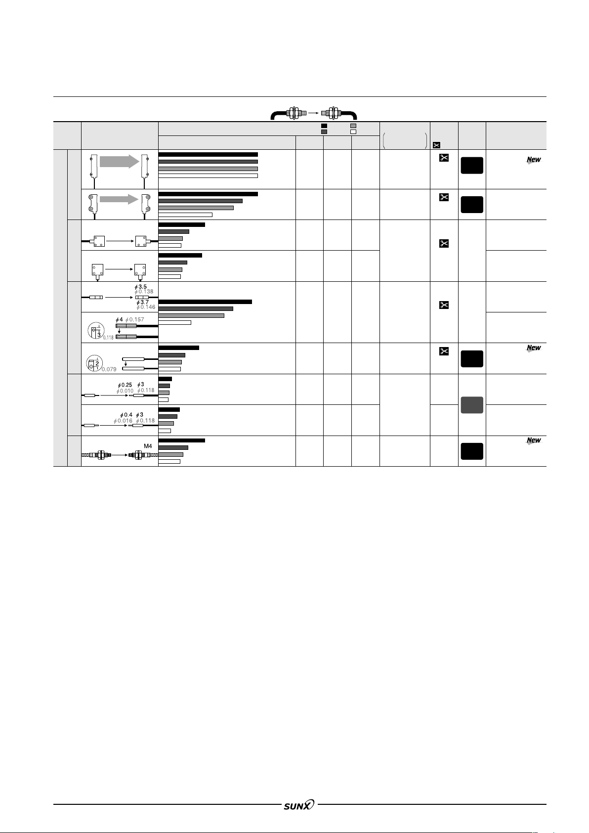
LIST OF FIBERS
08/2005
Special use fibers [Thru-beam type (one pair set)]
Shape of fiber head
Type
Wide beam
Array
(mm in)
Sensing width
32 mm
1.260 in
W5H69D20
W0.197H2.717D0.787
Sensing width
11 mm
0.433 in
W4.2H31D13.5
W0.165H1.220D0.531
Top sensing
W5H15D15 W0.197H0.591D0.591
Side sensing
W5H15D15 W0.197H0.591D0.591
Sensing range (mm in) (Note 1)
Red LED
1,500 59.055
1,100 43.307
750 29.528
650 25.591
330 12.992
220 8.661
115 4.528
590 23.228
290 11.417
200 7.874
100 3.937
3,500 137.795
3,500 137.795
3,500 137.795
3,500 137.795
(Note 3)
3,500 137.795
Blue LED
2,400 94.488
1,200 47.244
700 27.559
600 23.622
300 11.811
220 8.661
120 4.724
60 2.362
40 1.575
120 4.724
60 2.362
40 1.575
:LONG
:STD
Green LED
Infrared LED
1,200 47.244
600 23.622
350 13.780
300 11.811
150 5.906
110 4.331
60 2.362
30 1.181
20 0.787
60 2.362
30 1.181
20 0.787
800 31.496
400 15.748
240 9.449
220 8.661
110 4.331
:FAST
Min. sensing object
:S-D
under the optimum
condition (Note 2)
"0.3 mm
"0.012 in
opaque object
"0.25 mm
"0.010 in
80 3.150
opaque object
Horizontal:
48 1.890
"0.025 mm
24 0.945
"0.0010 in
18 0.709
opaque object
Vertical:
48 1.890
"0.45 mm
24 0.945
"0.018 in
18 0.709
opaque object
FX-301
Allowable
Fiber cable
bending
length
:
Free-cut
2 m
6.562 ft
2 m
6.562 ft
2 m
6.562 ft
radius
R10 mm
R0.394 in
R10 mm
R0.394 in
R25 mm
R0.984 in
Model No.
FT-A30
FT-A8
FT-AFM2
FT-AFM2E
2,000 78.740
1,000 39.370
Side-view
Special use
Narrow beam
Side-view
W2H1.5D20
Beam diameter:"0.125 mm "0.005 in
Sleeve part cannot be bent.
Beam diameter:"0.25 mm "0.010 in
Ultra-small diameter
Sleeve part cannot be bent.
Lens mountable
Tough flexible
Notes: 1) Please take care that the sensing range of the free-cut type fiber may be reduced by 20 % max. depending upon how the fiber is cut. In addition, the
Notes: 2) The minimum sensing object size is the value for red LED type. Please contact our office for information on the minimum sensing object size if using
Notes: 3) The fiber cable length practically limits the sensing range to 3,500 mm 137.795 in long.
infrared type is easily affected by humidity, so contact our office if using these sensors in environments with high humidity or where humidity levels can
fluctuate.
amplifiers other than red LED type.
The optimum condition is the condition when the sensitivity is set so that the sensing output just changes to light incident operation in the object absent
condition.
W0.079H0.059D0.787
250 9.843
180 7.087
100 3.937
18 0.709
10 0.394
8 0.315
3 0.118
80 3.150
50 1.969
36 1.417
15 0.591
230 9.055
110 4.331
350 13.780
320 12.598
800 31.496
500 19.685
650 25.591
400 15.748
200 7.874
130 5.118
80 3.150
35 1.378
10 0.394
3 0.118
2 0.079
1 0.039
14 0.551
7 0.276
4 0.157
130 5.118
64 2.520
45 1.772
200 7.874
100 3.937
65 2.559
1 0.039
6 0.236
3 0.118
2 0.079
64 2.520
32 1.260
22 0.866
150 5.906
75 2.953
40 1.575
4 0.157
2 0.079
1.5 0.059
10 0.394
5 0.197
3 0.118
130 5.118
64 2.520
45 1.772
"0.06 mm
"0.0024 in
opaque object
"0.02 mm
"0.0008 in
opaque object
"0.02 mm
"0.0008 in
opaque object
"0.05 mm
"0.0020 in
opaque object
2 m
6.562 ft
2 m
6.562 ft
500 mm
19.685 in
1 m
3.281 ft
1 m
3.281 ft
R25 mm
R0.984 in
R10 mm
R0.394 in
R5 mm
R0.197 in
R10 mm
R0.394 in
FT-K8
FT-KV8
FT-KV1
FT-E12
FT-E22
FT-P81X
75
Page 9
FX-301
08/2005
LIST OF FIBERS
Environment resistant fibers [Thru-beam type (one pair set)]
Shape of fiber head
Type
Heat-resistant
Environment resistant
(mm in)
350 C 662 F
Lens mountable
350 C 662 F
Sleeve 60 mm 2.362 in
Allows flexible wiring
200 C 392 F
Lens mountable
200 C 392 F
Lens mountable
130 C 266 F
Lens mountable
Easy mounting Rectangular head
SEMI S2 compliant
W7H15D13
W0.276
H0.591D0.512
Sensing range (mm in) (Note 1)
Red LED
550 21.654
280 11.024
200 7.874
90 3.543
310 12.205
140 5.512
100 3.937
50 1.969
550 21.654
280 11.024
200 7.874
90 3.543
155 6.102
440 17.323
300 11.811
530 20.866
880 34.646
3,500 137.795
1,500 59.055
1,000 39.370
Blue LED
100 3.937
50 1.969
35 1.378
44 1.732
22 0.866
14 0.551
100 3.937
50 1.969
35 1.378
72 2.835
36 1.417
26 1.024
320 12.598
160 6.299
120 4.724
:LONG
:STD
Green LED
Infrared LED
50 1.969
420 16.535
25 0.984
210 8.268
18 0.709
160 6.299
22 0.866
220 8.661
11 0.433
110 4.331
7 0.276
50 1.969
420 16.535
25 0.984
210 8.268
18 0.709
160 6.299
32 1.260
16 0.630
10 0.394
160 6.299
320 12.598
80 3.150
160 6.299
60 2.362
120 4.724
:FAST
Min. sensing object
:S-D
under the optimum
condition (Note 2)
"0.04 mm
"0.0016 in
opaque object
"0.02 mm
"0.0008 in
70 2.756
opaque object
"0.04 mm
"0.0016 in
opaque object
70 2.756
"0.06 mm
35 1.378
"0.0024 in
25 0.984
opaque object
"4 mm
"0.157 in
opaque object
Fiber cable
length
:
Free-cut
2 m
6.562 ft
1 m
3.281 ft
2 m
6.562 ft
1 m
3.281 ft
2 m
6.562 ft
2 m
6.562 ft
Allowable
bending
radius
R25 mm
R0.984 in
Fiber
R25 mm
R0.984 in
Sleeve
R10 mm
R0.394 in
R10 mm
R0.394 in
R25 mm
R0
.984 in
R25 mm
R
0.984 in
Model No.
FT-H35-M2
FT-H35-M2S6
FT-H20W-M1
FT-H20W-M2
FT-H20-M1
FT-H13-FM2
FT-Z802Y
160 6.299
160 6.299
3,500 137.795
1,500 59.055
1,000 39.370
400 15.748
280 11.024
140 5.512
470 18.504
230 9.055
165 6.496
220 8.661
530 20.866
800 31.496
Chemical-resistant
Side-view
Lens mountable
80 3.150
Vacuum
Notes: 1)
Please take care that the sensing range of the free-cut type fiber may be reduced by 20 % max. depending upon how the fiber is cut. In addition, the infrared
type is easily affected by humidity, so contact our office if using these sensors in environments with high humidity or where humidity levels can fluctuate.
Notes: 2)
The minimum sensing object size is the value for red LED type. Please contact our office for information on the minimum sensing object size if using amplifiers other than red
LED type. The optimum condition is the condition when the sensitivity is set so that the sensing output just changes to light incident operation in the object absent
Notes: 3) The allowable cutting range is 500 mm 19.685 in from the end that the amplifier inserted.
75 2.953
35 1.378
100 3.937
80 3.150
50 1.969
120 4.724
60 2.362
35 1.378
100 3.937
50 1.969
30 1.181
36 1.417
18 0.709
12 0.472
80 3.150
50 1.969
80 3.150
40 1.575
25 0.984
46 1.811
23 0.906
16 0.630
18 0.709
9 0.354
6 0.236
400 15.748
200 7.874
150 5.906
75 2.953
38 1.496
24 0.945
70 2.756
35 1.378
22 0.866
28 1.102
14 0.551
10 0.394
"0.08 mm
"0.003 in
opaque object
"0.02 mm
"0.0008 in
opaque object
2 m
6.562 ft
(Note 3)
1 m
3.281 ft
R30 mm
R1.181 in
R200 mm
R7.874 in
R30 mm
R1.181 in
FT-L8Y
FT-V8Y
FT-6V
FT-60V
condition.
The vacuum type fiber must be used with the following products as a set.
FT-J6: Fiber at atmospheric side (one pair set) FV-BR1: Photo-terminal (one pair set)
Semi-standard fibers (Custom made per order)
The fiber cable length or sleeve length of the standard fibers can be modified at your request. Select the fiber cable length (symbol ) or the sleeve length
(symbol f ) from the table below.
Type
Standard threaded
head (free-cut)
With sleeve
With large diameter lens
Small diameter threaded
head with sleeve (free-cut)
Basic model No.
FT-FM
FT-FM -S f
FT-FM L
FT-NFM2-S f
FT-WA30-
Wide beam
FT-WA8-
FT-A30-
(Unit: m ft)
3 9.843, 4 13.123, 5 16.404, 10 32.808,
15 49.213, 20 65.617,25 82.021, 30 98.425
2 6.562 (Note), 3 9.843, 4 13.123, 5 16.404,
10 32.808, 15 49.213, 20 65.617, 25 82.021, 30 98.425
20 65.617, 30 98.425
5 16.404
1 0.394, 2 0.787, 3 1.181, 4 1.575, 5 1.969, 6 2.362,
7 2.756, 8 3.150, 9 3.543, 10 3.937, 11 4.331, 12
4.724
1 0.394, 2 0.787, 3 1.181, 4 1.575, 5 1.969, 6 2.362,
7 2.756, 8 3.150, 9 3.543, 10 3.937, 11 4.331, 12
4.724
Sleeve length
f
(Unit: cm in)
Fiber cable length
FT-A8-
200C 392F heat-resistant
350C 662F heat-resistant
Chemical-resistant
Note:
The standard fiber has a 2 m 6.562 ft fiber cable length and a 4 cm 1.575 in or 9 cm 3.543 in sleeve length.
FT-H20-M
FT-H35-M
FT-Z80 Y
2 6.562, 3 9.843
3 9.843
5 16.404, 7 22.966
Correlation between sensing
range attenuation coefficient and
fiber cable length
The longer the fiber cable, the shorter the
sensing range.
76
Page 10
LIST OF FIBERS
08/2005
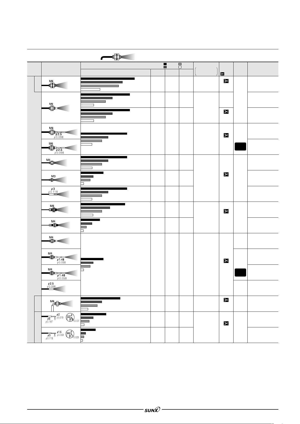
Standard fibers (Reflective type)
Shape of fiber head
Type
Long sensing range
Coaxial
Sleeve 90 mm 3.543 in
Sleeve 40 mm 1.575 in
Small diameter
Standard
Sleeve 90 mm 3.543 in
Sleeve 40 mm 1.575 in
(mm in)
Sensing range (mm in ) (Note 1, 2)
35 1.378
16 0.630
28 1.102
13 0.512
35 1.378
16 0.630
75 2.953
47 1.850
47 1.850
85 3.346
39 1.535
85 3.346
39 1.535
45 1.772
85 3.346
39 1.535
85 3.346
42 1.654
75 2.953
38 1.496
45 1.772
Red LED
140 5.512
100 3.937
140 5.512
100 3.937
110 4.331
110 4.331
90 3.543
110 4.331
120 4.724
90 3.543
220 8.661
160 6.299
310 12.205
310 12.205
270 10.630
270 10.630
270 10.630
260 10.236
480 18.898
Blue LED
80 3.150
40 1.575
26 1.024
46 1.811
23 0.906
15 0.591
46 1.811
23 0.906
15 0.591
46 1.811
23 0.906
15 0.591
46 1.811
23 0.906
15 0.591
16 0.630
8 0.315
5 0.197
46 1.811
23 0.906
15 0.591
46 1.811
23 0.906
15 0.591
16 0.630
8 0.315
5 0.197
16 0.630
8 0.315
5 0.197
:LONG
:STD
Green LED
Infrared LED
42 1.654
21 0.827
14 0.551
24 0.945
12 0.472
8 0.315
24 0.945
12 0.472
8 0.315
24 0.945
12 0.472
8 0.315
24 0.945
12 0.472
8 0.315
8 0.315
4 0.157
2 0.079
24 0.945
12 0.472
8 0.315
24 0.945
12 0.472
8 0.315
8 0.315
4 0.157
2 0.079
8 0.315
4 0.157
2 0.079
:FAST
Min. sensing object
:S-D
at the maximum
sensitivity (Note 3)
26 1.654
13 0.827
9 0.551
90 3.543
45 1.772
30 1.181
20 0.787
10 0.394
7 0.276
20 0.787
10 0.394
7 0.276
20 0.787
10 0.394
7 0.276
6 0.236
3 0.118
2 0.079
20 0.787
10 0.394
7 0.276
20 0.787
10 0.394
7 0.276
4 0.157
2 0.079
1.5 0.059
6 0.236
3 0.118
2 0.079
"0.02 mm
"0.0008 in
gold wire
"0.02 mm
"0.0008 in
gold wire
"0.02 mm
"0.0008 in
gold wire
"0.02 mm
"0.0008 in
gold wire
"0.02 mm
"0.0008 in
gold wire
"0.02 mm
"0.0008 in
gold wire
FX-301
Allowable
Fiber cable
bending
length
:
Free-cut
2 m
6.562 ft
500 mm
19.685 in
2 m
6.562 ft
2 m
6.562 ft
2 m
6.562 ft
2 m
6.562 ft
(Note 4)
2 m
6.562 ft
radius
R25 mm
R0.984 in
Fiber
R25 mm
R0.984 in
Sleeve
R10 mm
R0.394 in
R25 mm
R0.984 in
R25 mm
R
0.984 in
R25 mm
R0.984 in
Fiber
R25 mm
R0.984 in
Sleeve
R10 mm
R0.394 in
Model No.
FD-B8
FD-5
FD-FM2
FD-FM2S
FD-FM2S4
FD-T80
FD-T40
FD-S80
FD-N8
FD-N4
FD-NFM2
FD-NFM2S
FD-NFM2S4
R25 mm
R0.984 in
32 1.260
16 0.630
85 3.346
60 2.362
30 1.181
45 1.772
32 1.260
Sleeve part cannot be bent.
Small diameter
Side-view Elbow
Sleeve part cannot be bent.
Notes: 1) The sensing range is specified for white non-glossy paper (FD-B8, FD-5, FD-FM2, FD-FM2S, FD-FM2S4, FD-N8, FD-T80, FD-S80 and FD-R80:
Notes: 2) Please take care that the sensing range of the free-cut type fiber may be reduced by 20 % max. depending upon how the fiber is cut. In addition, the
Notes: 3) The minimum sensing object size is the value for red LED type at maximum sensitivity. Please contact our office for information on the minimum sensing
Notes: 4) The fiber cutter is not supplied as an accessor y with FD-N8 and FD-N4. Please order it separately.
400 mm 15.74815.748 in, FD-T40, FD-N4, FD-NFM2, FD-NFM2S, FD-NFM2S4, FD-SNFM2, FD-SFM2SV2 and FD-V41: 200200 mm
400
7.874 in) as the object.
7.874
infrared type is easily affected by humidity, so contact our office if using these sensors in environments with high humidity or where humidity levels can
fluctuate.
object size if using amplifiers other than red LED type.
Also, note that the corresponding setting distance is different from the rated sensing distance.
16 0.630
25 0.984
17 0.669
9 0.354
55 2.165
185 7.283
100 3.937
16 0.630
10 0.394
14 0.551
7 0.276
4 0.157
6 0.236
3 0.118
8 0.315
5 0.197
7 0.276
3.5 0.138
3 0.118
10 0.472
5 0.197
3 0.118
4 0.157
"0.02 mm
"0.0008 in
gold wire
"0.02 mm
"0.0008 in
gold wire
2 m
6.562 ft
2 m
6.562 ft
R25 mm
R0.984 in
R25 mm
R0.984
FD-SNFM2
FD-R80
FD-SFM2SV2
in
FD-V41
77
Page 11
FX-301
08/2005
LIST OF FIBERS
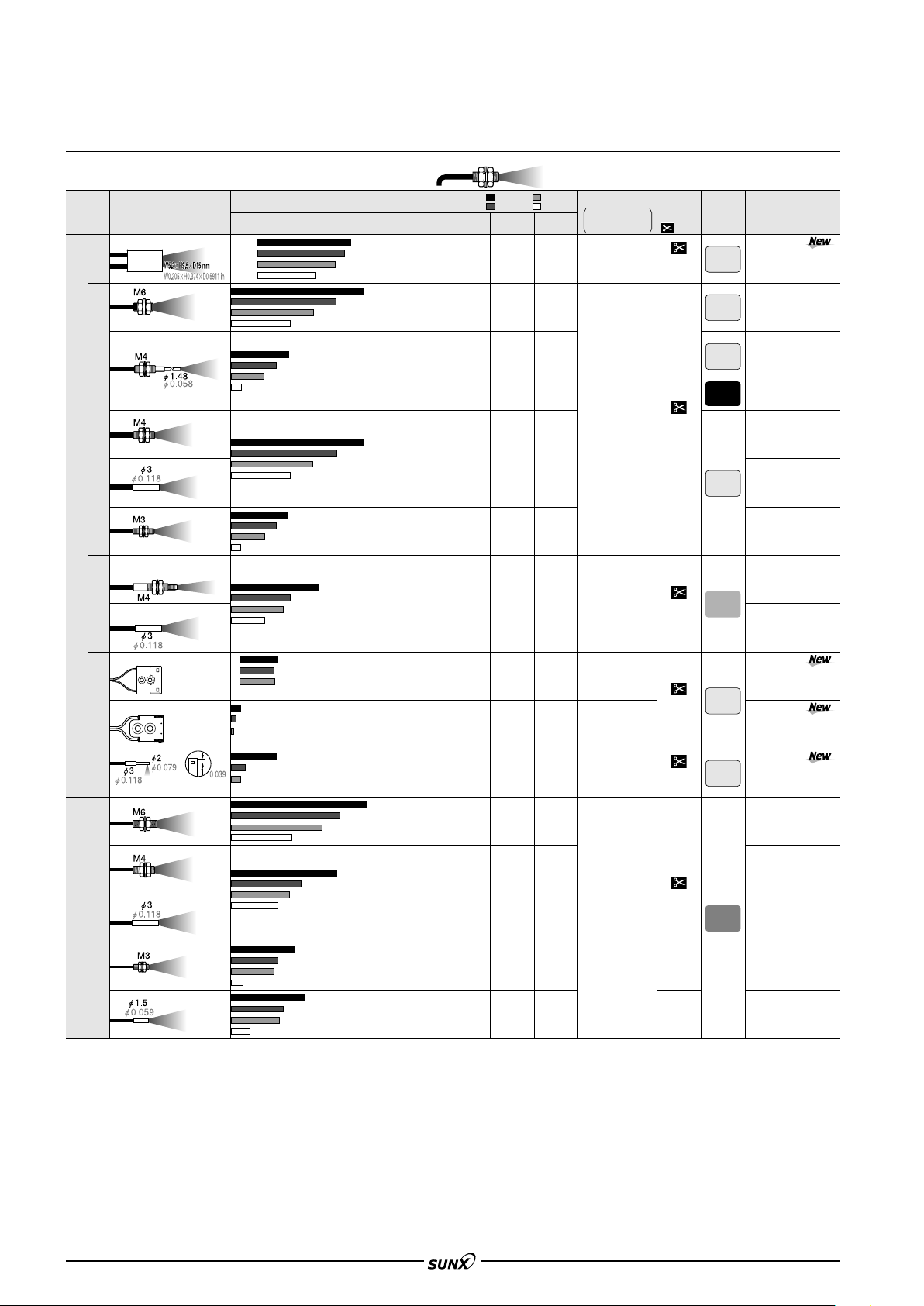
Sharp bending fibers / Flexible fibers (Reflective type)
Shape of fiber head
Type
Long sensing range
Standard
Sharp bending
High precision
Fixed-focus reflective
Side-view
(mm in)
Long sensing range Rectangular head
Sleeve 40 mm 1.575 in
Small spot for sensing minute objects
Coaxial Lens mountable
For sensing minute objects Coaxial
Glass substrate detection
Specular object detection
Sleeve part cannot be bent.
W24H21D4
W0.945H0.8270.157
W15H19D3
W0.591H0.7480.118
Sensing range (mm in) (Note 1, 2)
Red LED
20 to 480 0.787 to 18.898
20 to 230 0.787 to 9.055
20 to 170 0.787 to 6.693
25 to 100 0.984 to 3.937
60 2.362
32 1.260
30 1.181
15 0.591
12 0.472
5 0.197
60 2.362
32 1.260
30 1.181
15 0.591
12 0.472
5 0.197
32 1.260
25 0.984
11 0.433
6.5 to 14 0.256 to 0.551 (Convergent point 8 0.315)
7 to 12 0.276 to 0.472 (Convergent point 8 0.315)
7.5 to 12 0.295 to 0.472 (Convergent point 8 0.315)
Cannot use
0.6 to 3.5 0.024 to 0.138 (Convergent point 2 0.079)
0.9 to 2.7 0.035 to 0.106 (Convergent point 2 0.079)
1 to 2.5 0.039 to 0.098 (Convergent point 2 0.079)
Cannot use
15 0.591
7 0.276
5 0.197
Cannot use
35 1.378
90 3.543
90 3.543
65 2.559
100 3.937
70 2.756
190 7.480
190 7.480
220 8.661
Blue LED
23 0.906
11 0.433
8 0.315
5 0.197
2.5 0.098
1.5 0.059
23 0.906
11 0.433
8 0.315
5 0.197
2.5 0.098
1.5 0.059
11 0.433
5 0.197
3 0.118
40 1.575
20 0.787
13 0.512
:LONG
:STD
Green LED
Infrared LED
14 0.551
7 0.276
4 0.157
3 0.118
1.5 0.059
1 0.039
14 0.551
7 0.276
4 0.157
3 0.118
1.5 0.059
1 0.039
6 0.236
3 0.118
2 0.079
20 0.787
10 0.394
7 0.276
:FAST
Min. sensing object
:S-D
at the maximum
sensitivity (Note 3)
"0.3 mm
"0.012 in
copper wire
11 0.433
5.5 0.217
3 0.118
2 0.079
1 0.039
11 0.433
5.5 0.217
3 0.118
2 0.079
1 0.039
5 0.197
2.5 0.098
1.5 0.059
"1.9 mm
"0.075 in
metal pipe (gray)
18 0.709
9 0.354
6 0.236
"0.02 mm
"0.0008 in
gold wire
"0.02 mm
"0.0008 in
gold wire
"0.08 mm
"0.003 in
gold wire
"0.02 mm
"0.0008 in
gold wire
Fiber cable
length
:
Free-cut
2 m
6.562 ft
2 m
6.562 ft
2 m
6.562 ft
2 m
6.562 ft
2 m
6.562 ft
Allowable
bending
radius
R1 mm
R0.039 in
R1 mm
R0.039 in
Fiber
R1 mm
R0.039 in
Sleeve
R10 mm
R0.394 in
R1 mm
R0.039 in
R2 mm
R0.079 in
R1 mm
R0.039 in
R1 mm
R0.039 in
Model No.
FD-WKZ1
FD-W8
FD-W44
FD-WT8
FD-WS8
FD-WT4
FD-WG4
FD-WSG4
FD-WL41
FD-WL42
FD-WV42
FD-P80
20 0.787
90 3.543
Standard
Flexible
6 0.236
Small diameter
Notes: 1) The sensing range is specified for white non-glossy paper [100100 mm 3.9373.937 in (FD-WKZ1, FD-W8, FD-WT8, FD-WS8 and FD-P80:
Notes: 2) Please take care that the sensing range of the free-cut type fiber may be reduced by 20 % max. depending upon how the fiber is cut. In addition, the
Notes: 3) The minimum sensing object size is the value for red LED type at maximum sensitivity. Please contact our office for information on the minimum sensing
78
400 mm 15.748 15.748 in, FD-WG4, FD-WSG4, FD-P60 and FD-P50: 200 200 mm 7.8747.874 in, FD-WL41: glass substrate
400
100t 2 mm 3.9373.937t 0.472 in)] as the object.
100
infrared type is easily affected by humidity, so contact our office if using these sensors in environments with high humidity or where humidity levels can
fluctuate.
object size if using amplifiers other than red LED type.
Also, note that the corresponding setting distance is different from the rated sensing distance. However, with the fixed-focus reflective type, when the
sensitivity is at MAX., it is only possible to detect the minimum size of the sensing object at a distance corresponding to the convergent point.
9 0.354
45 1.772
30 1.181
16 0.630
36 1.417
18 0.709
14 0.551
25 0.984
19 0.748
50 1.969
10 0.394
6 0.236
5 0.197
2.5 0.098
1.5 0.059
8 0.315
4 0.157
2.5 0.098
10 0.394
1.5 0.059
1.5 0.059
5 0.197
3 0.118
3 0.118
1 0.039
4 0.157
2 0.079
8 0.315
4 0.157
2.5 0.098
2 0.079
1 0.039
7 0.276
3.5 0.138
2 0.079
"0.02 mm
"0.0008 in
gold wire
2 m
6.562 ft
1 m
3.281 ft
R4 mm
R0.157 in
FD-P60
FD-P50
FD-P40
FD-P2
Page 12
FX-301
08/2005
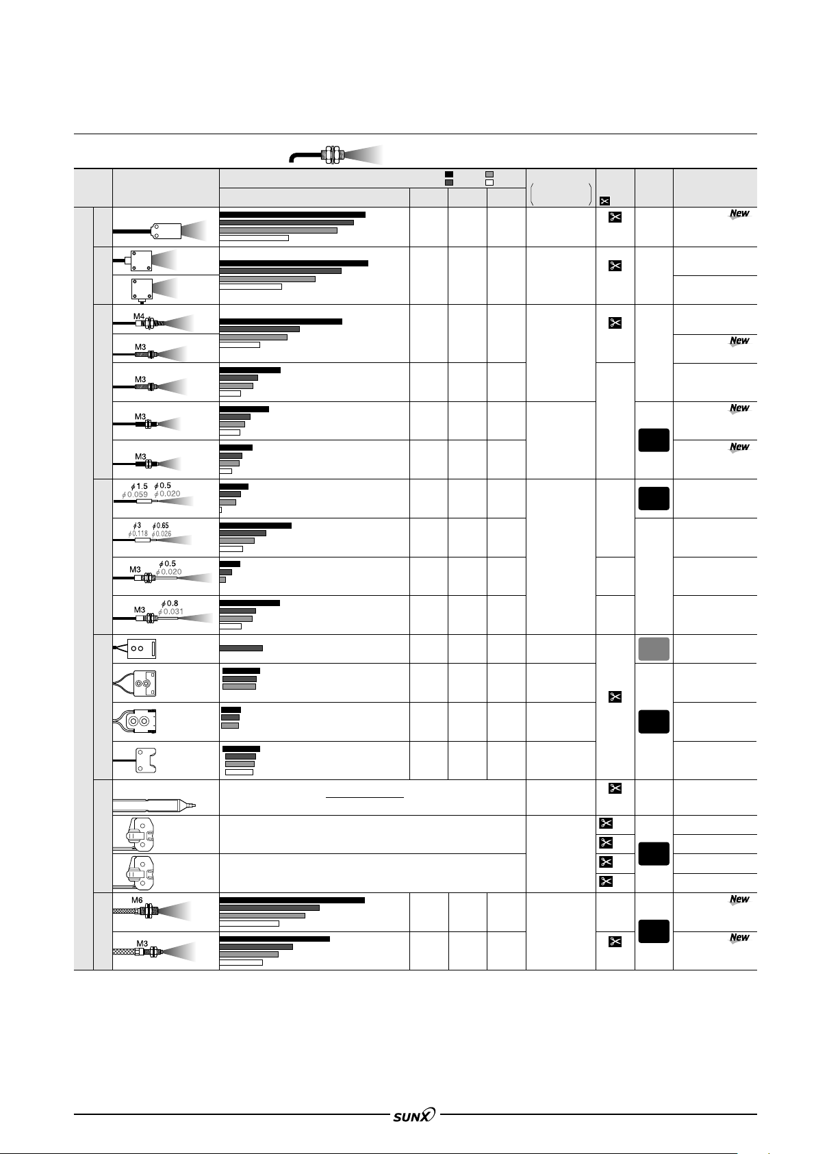
LIST OF FIBERS
Special use fibers (Reflective type)
:LONG
:FAST
Shape of fiber head
Type
(mm in)
W7H15D30 W0.276H0.591D1.181
Wide beam
Top sensing
W5H20D20
W0.197H0.787D0.787
Array
Side sensing
W5H20D20
W0.197H0.787D0.787
Coaxial Lens mountable
Coaxial Lens mountable
Coaxial Lens mountable
Coaxial Lens mountable
High precision
Coaxial Lens mountable
Sleeve part cannot be bent.
Coaxial
Sleeve part cannot be bent.
Sleeve part cannot be bent.
Ultra-small diameter
Coaxial
Special use
Sleeve part cannot be bent.
Fixed-focus reflective
Contact type
Liquid level sensing
Small spot for sensing minute objects
Glass substrate detection
SEMI S2 compliant
W17H29D3.8
W0.669H1.142D0.150
Glass substrate detection
W24H21D4
W0.945H0.827D0.157
Specular object detection
W15H19D3
W0.591H0.748D0.118
W6H18D14
W0.236H0.709D0.551
"6 "0.236
Mountable on pipe
Standard
W25H13D20
W0.984H0.512D0.787
Mountable on pipe For PFA, wall
thickness 1 mm 0.039 in pipe
W25H13D20
W0.984H0.512D0.787
Tough flexible
Coaxial High precision
Notes: 1)
Notes: 2) Please take care that the sensing range of the free-cut type fiber may be reduced by 20 % max. depending upon how the fiber is cut. In addition, the
The sensing range is specified for white non-glossy paper [100100 mm 3.9373.937 in (FD-A15, FD-G4, FD-G6X:200200 mm 7.8747.874 in,
FD-AFM2, FD-AFM2E, FD-P81X: 400
glass substrate 100
100t 2 mm 3.9373.937t 0.079 in)] as the object.
Sensing range (mm in) (Note 1, 2)
Red LED
78 3.071
55 2.165
100 3.937
110 4.331
110 4.331
50 1.969
39 1.535
42 1.654
19 0.748
38 1.496
18 0.709
14 0.551
6 0.236
25 0.984
12 0.472
9 0.354
5 0.197
15 0.591
8 0.315
5 0.197
3 0.118
11 0.433
6 0.236
4 0.157
1 0.039
45 1.772
23 0.906
17 0.669
7 0.276
5 0.197
3 0.118
2 0.079
Cannot use
38 1.496
18 0.709
14 0.551
6 0.236
0 to 20 0 to 0.787
2.5 to 18 0.098 to 0.709 (Convergent point 8 0.315)
3 to 16 0.118 to 0.630 (Convergent point 8 0.315)
3.5 to 15 0.138 to 0.591 (Convergent point 8 0.315)
Cannot use
0.5 to 4 0.020 to 0.157 (Convergent point 2 0.079)
1 to 3.8 0.039 to 0.150 (Convergent point 2 0.079)
1.3 to 3.5 0.051 to 0.138 (Convergent point 2 0.079)
Cannot use
2.5 to 18 0.098 to 0.709 (Convergent point 6 0.236)
4 to 12 0.157 to 0.472 (Convergent point 6 0.236)
4.5 to 11 0.177 to 0.433 (Convergent point 6 0.236)
4.8 to 9.5 0.189 to 0.374 (Convergent point 6 0.236)
200 7.874
150 5.906
220 8.661
Blue LED
4.5 to 9.5 0.177 to 0.374
:STD
Green LED
25 0.984
15 0.591
40 1.575
20 0.787
13 0.512
22 0.866
11 0.433
8 0.315
6 0.236
3 0.118
2 0.079
5 0.197
2 0.079
1 0.039
2 0.079
1 0.039
2 0.079
1 0.039
6 0.236
3 0.118
2 0.079
6 0.236
3 0.118
2 0.079
5 to 9 0.197 to 0.354
5.5 to 8 0.217 to 0.315
18 0.709
9 0.354
5 0.197
12 0.472
6 0.236
4 0.157
3 0.118
1.5 0.059
1 0.039
2 0.079
1 0.039
1 0.039
1 0.039
3 0.118
1.5 0.059
1 0.039
3 0.118
1.5 0.059
1 0.039
5 to 9 0.197 to 0.354
5.5 to 8 0.217 to 0.315
Applicable pipe diameter:
Outer dia. "6 to "26 mm "0.236 to "1.024 in transparent pipe
[
PVC, fluorine resin, polycarbonate, acrylic, glass, wall thickness 1 to 3 mm 0.039 to 0.118 in
Applicable pipe diameter:
Outer dia. "6 to "26 mm "0.236 to "1.024 in transparent pipe
[PFA (fluorine resin) or equivalently transparent pipe, wall thickness 1 mm 0.039 in]
80 3.150
60 2.362
35 1.378
45 1.772
35 1.378
20 0.787
400 mm 15.74815.748 in, FD-L43: glass substrate 7652t 1.1 mm 2.9922.047t 0.043 in, FD-L41:
185 7.283
90 3.543
32 1.260
16 0.630
10 0.394
22 0.866
11 0.433
6 0.236
16 0.630
8 0.315
5 0.197
12 0.472
6 0.236
4 0.157
Min. sensing object
:S-D
12 0.472
6 0.236
4 0.157
7 0.276
3.5 0.138
2 0.079
10 0.394
5 0.197
3 0.118
6 0.236
3 0.118
2 0.079
3 0.118
1.5 0.059
1 0.039
1 0.039
6 0.236
3 0.118
2 0.079
4 0.157
2 0.079
1.5 0.059
at the maximum
sensitivity (Note 3)
"0.02 mm
"0.0008 in
gold wire
"0.02 mm
"0.0008 in
gold wire
"0.02 mm
"0.0008 in
gold wire
"0.04 mm
"0.0016 in
gold wire
"0.02 mm
"0.0008 in
gold wire
(LCD glass)
"0.06 mm
"0.0024 in
gold wire
"0.03 mm
"0.0012 in
gold wire
"0.02 mm
"0.0008 in
gold wire
Infrared LED
4.5 to 9.5 0.177 to 0.374
(Liquid)
]
(Liquid)
30 1.181
15 0.591
10 0.394
18 0.709
9 0.354
5 0.197
"0.02 mm
"0.0008 in
gold wire
infrared type is easily affected by humidity, so contact our office if using these sensors in environments with high humidity or where humidity levels can
fluctuate.
Notes: 3) The minimum sensing object size is the value for red LED type at maximum sensitivity. Please contact our office for information on the minimum sensing
object size if using amplifiers other than red LED type.
Also, note that the corresponding setting distance is different from the rated sensing distance. However, with the fixed-focus reflective type, when the
sensitivity is at MAX., it is only possible to detect the minimum size of the sensing object at a distance corresponding to the convergent point.
Notes: 4) Following is the allowable cutting range from the end that the amplifier is inserted FD-F8Y: 1,000 mm 39.370 in, FD-G6X: 700 mm 27.559 in.
Fiber cable
length
:
Free-cut
2 m
6.562 ft
2 m
6.562 ft
2 m
6.562 ft
500 mm
19.685 in
1 m
3.281 ft
500 mm
19.685 in
1 m
3.281 ft
2 m
6.562 ft
2 m 6.562 ft
(Note 4)
2 m
6.562 ft
5 m
16.404 ft
2 m
6.562 ft
5 m
16.404 ft
1 m
3.281 ft
1 m 3.281 ft
(Note 4)
Allowable
bending
radius
R25 mm
R0.984 in
R25 mm
R0.984 in
R25 mm
R0.984 in
R10 mm
R0.394 in
R10 mm
R0.394 in
R25 mm
R0.984 in
R4
R0.157
R10 mm
R0.394 in
Protective tube
R40 mm R1.575 in
Fiber
R15 mm R0.591 in
R10 mm
R0.394 in
R10 mm
R0.394 in
Model No.
FD-A15
FD-AFM2
FD-AFM2E
FD-G4
FD-G6
FD-EG1
FD-EG2
FD-EG3
FD-E12
FD-E22
FD-EN500S1
FD-ENM1S1
FD-L43
FD-L41
FD-L42
FD-L4
FD-F8Y
FD-F41
FD-F91
FD-F4
FD-F9
FD-P81X
FD-G6X
79
Page 13
FX-301
08/2005
LIST OF FIBERS
Environment resistant fibers (Reflective type)
:LONG
:FAST
Shape of fiber head
Type
Heat-resistant
Environment resistant
Vacuum
Notes: 1)
Notes: 2)
Notes: 3) The minimum sensing object size is the value for red LED type at maximum sensitivity. Please contact our office for information on the minimum sensing
(mm in)
350 C 662 F Coaxial
350 C 662 F Sleeve 60 mm 2.362 in
200 C 392 F Coaxial
350 C 662 F Sleeve 90 mm 3.543 in
200 C 392 F Coaxial
300 C 572 F Glass substrate detection
Fixed-focus reflective type
180 C 356 F Glass substrate detection
Fixed-focus reflective type
130 C 266 F
The sensing range is specified for white non-glossy paper [400400 mm 15.74815.748 in (FD-H30-L32, FD-H18-L31: glass substrate 5050 mm 1.9691.969 in)] as the object.
Please take care that the sensing range of the free-cut type fiber may be reduced by 20 % max. depending upon how the fiber is cut. In addition, the infrared
type is easily affected by humidity, so contact our office if using these sensors in environments with high humidity or where humidity levels can fluctuate.
object size if using amplifiers other than red LED type. Also, note that the corresponding setting distance is different from the rated sensing distance.
W19H27D5
H1.063
W0.748
D0.197
W19H27D5
W0.748H1.063
D0.197
Sensing range (mm in) (Note 1, 2)
Red LED
270 10.630
140 5.512
100 3.937
47 1.850
160 6.299
80 3.150
57 2.244
26 1.024
100 3.937
47 1.850
0 to 15 0 to 0.591
0 to 10 0 to 0.394
1 to 8 0.039 to 0.315
2 to 6 0.079 to 0.236
100 3.937
47 1.850
75 2.953
52 2.047
26 1.024
140 5.512
140 5.512
165 6.496
270 10.630
310 12.205
Blue LED
36 1.417
18 0.709
12 0.472
22 0.866
11 0.433
7 0.276
36 1.417
18 0.709
12 0.472
20 0.787
11 0.433
7 0.276
26 1.024
13 0.512
9 0.354
:STD
Green LED
20 0.787
10 0.394
7 0.276
12 0.472
6 0.236
4 0.157
20 0.787
10 0.394
7 0.276
20 0.787
11 0.433
7 0.276
14 0.551
7 0.276
4 0.157
Min. sensing object
:S-D
140 5.512
70 2.756
45 1.772
80 3.150
40 1.575
28 1.102
140 5.512
70 2.756
45 1.772
25 0.984
12 0.472
8 0.315
21 0.827
10 0.394
6 0.236
at the maximum
sensitivity (Note 3)
Infrared LED
"0.02 mm
"0.0008 in
gold wire
"0.02 mm
"0.0008 in
gold wire
"0.02 mm
"0.0008 in
gold wire
"0.02 mm
"0.0008 in
gold wire
"0.02 mm
"0.0008 in
gold wire
"0.02 mm
"0.0008 in
gold wire
Fiber cable
length
:
Free-cut
2 m
6.562 ft
1 m
3,281 ft
1 m
3,281 ft
1 m
3,281 ft
2 m
6.562 ft
2 m
6.562 ft
2 m
6.562 ft
1 m
3,281 ft
Allowable
bending
radius
R25 mm
R0.984 in
Fiber
R25 mm
R0.984 in
Sleeve
R10 mm
R0.394 in
R25 mm
R0.984 in
Fiber
R25 mm
R0.984 in
Sleeve
R10 mm
R0.394 in
R25 mm
R0.984 in
R25 mm
R0
.984 in
R25 mm
R0.984 in
R200 mm
R7.874 in
Model No.
FD-H35-M2
FD-H35-M2S6
FD-H20-M1
FD-H35-20S
FD-H20-21
FD-H30-L32
FD-H18-L31
FD-H13-FM2
FD-6V
The vacuum type fiber must be used with the following products as a set.
FT-J6: Fiber at atmospheric side (one pair set)
FV-BR1: Photo-terminal (one pair set)
Semi-standard fibers (Custom made per order)
The fiber cable length or sleeve length of the standard fibers can be modified at your request. Select the fiber cable length (symbol ) or the sleeve length
(symbol f ) from the table below.
Fiber cable length
Type
Standard threaded
head (free-cut)
With sleeve
Small diameter
threaded head with
sleeve (free-cut)
200C 392F heat-resistant
350C 662F heat-resistant
Note:
The standard fiber has a 2 m 6.562 ft fiber cable length and a 4 cm 1.575 in or 9 cm 3.543 in sleeve length.
Basic model No.
FD-FM
FD-FM -S f
FD-NFM2-S f
FD-H20-M
FD-H35-M
(Unit: m ft)
3 9.843, 4 13.123, 5 16.404,
10 32.808, 15 49.213, 20 65.617
2 6.562 (Note), 3 9.843, 4 13.123,
5 16.404, 10 32.808, 15 49.213,
20 65.617
2 6.562, 3 9.843
3 9.843
1 0.394, 2 0.787, 3 1.181, 4 1.575,
5 1.969, 6 2.362, 7 2.756, 8 3.150,
9 3.543, 10 3.937, 11 4.331, 12 4.724
1 0.394, 2 0.787, 3 1.181, 4 1.575,
5 1.969, 6 2.362, 7 2.756, 8 3.150,
9 3.543, 10 3.937, 11 4.331, 12 4.724
Sleeve length
f
(Unit: cm in)
Correlation between sensing
range attenuation coefficient and
fiber cable length
The longer the fiber cable, the
shorter the sensing range.
Accessories (attached with fibers)
Fiber cutter
• FX-CT2
Notes: 1)
Fiber cutter is not supplied as accessory along with FT-NB8, FT-N8, FD-N8 and FD-N4. Please order it separately.
The fiber attachment is not attached with FT-N8/NB8/P80 and FD-N8/P80. The previous FX-AT10 attachment is attached with FD-N4.
Notes: 2)
Fiber attachment
• FX-AT2
(for fixed-length fiber)
• FX-AT3
for "2.2 mm
()
"0.087 in fiber
• FX-AT4
(for "1 mm "0.039 in fiber)
• FX-AT5
(for "1.3 mm "0.051 in fiber)
• FX-AT6
for "1 mm "0.039 in and "1.3 mm
(
"0.051 in mixed fiber
)
80
Page 14
FX-301
08/2005
FIBER OPTIONS
Lens (For thru-beam type fiber)
Designation
Model No.
Increases the sensing range by 5 times or
more.
• Ambient temperature:
60 to 350 C
Expansion
lens
(Note 1)
FX-LE1
76 to 662 F
Tremendously increases the sensing
range with large diameter lenses.
• Ambient temperature:
60 to 350 C
Superexpansion
lens
FX-LE2
76 to 662 F
(Note 1)
For thru-beam type fiber
Beam axis is bent by 90 .
• Ambient temperature:
60 to 300 C
76 to 572 F
Sideview
FX-SV1
lens
Expansion
lens for
vacuum
FV-LE1
fiber
(Note 1)
Notes: 1)
Notes: 2) The sensing ranges are the values for red LED type amplifier. Please contact our office for details on sensing ranges for other types of amplifiers.
Be careful when installing the thru-beam type fiber equipped with the expansion lens, as the beam envelope becomes narrow and alignment is difficult.
Especially when installing a fiber with many cores (sharp bending fibers and heat-resistant glass fiber) please be sure to use it only after you have adjusted it sufficiently.
Sensing range increases by 15 times or
more.
• Ambient temperature:
40 to 120 C
40 to 248 F
Notes: 3) The fiber cable length practically limits the sensing range to 3.500 mm 137.795 in long (FT-H20W-M1 and FT-H20-M1: 1,600 mm 62.992 in).
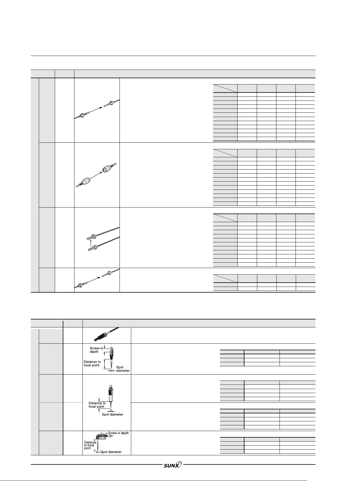
Lens (For reflective type fiber)
Designation
Pinpoint
spot lens
Zoom lens
Finest spot
lens
For reflective type fiber
Finest spot
lens
Zoom lens
Side-view
type
()
Note:
The sensing ranges are the values when used in combination with red LED type amplifier. Please contact our office for details on sensing distances for other types of amplifier.
Model No.
FX-MR1
FX-MR2
FX-MR3
FX-MR6
FX-MR5
Pinpoint spot of "0.5 mm "0.020 in. Enables detection of minute objects or small marks.
• Applicable fibers: FD-WG4, FD-G4 • Distance to focal point: 6
• Ambient temperature:
The spot diameter is adjustable from "0.7 mm
"0.028 in to "2 mm "0.079 in according to
how much the fiber is screwed in.
• Applicable fibers: FD-WG4, FD-G4
Ambient temperature:40 to70 C 40 to 158 F
•
• Accessory: MS-EX-3 (mounting bracket)
Extremely fine spot of "0.3 mm "0.012 in approx.
achieved.
•
Applicable fibers:
•
Ambient temperature:40 to 70 C 40 to 158 F
Extremely fine spot of "0.1 mm "0.004 in
achieved.
•
Applicable fibers:
•
Ambient temperature:20 to 60 C 4 to 140 F
FX-MR2 is converted into a side-view type and
can be mounted in a very small space.
• Applicable fibers: FD-WG4, FD-G4
Ambient temperature:40 to 70 C 40 to 158 F
•
Description
Sensing range (mm) [Lens on both sides]
Sensing range (mm) [Lens on both sides]
Sensing range (mm) [Lens on both sides]
Sensing range (mm) [Lens on both sides] (Note 2)
Description
40 to 70 C 40 to 158 F
FD-WG4, FD-G4, FD-EG1,
FD-EG3, FD-G6X, FD-G6
FD-WG4, FD-G4, FD-EG1
FD-EG3, FD-G6X, FD-G6
FD-EG2,
approx.
,FD-EG2,
Mode
Fiber
FT-B8
FT-FM2
FT-T80
FT-R80
FT-W8
FT-P80
FT-P60
FT-P81X
FT-H35-M2
FT-H20W-M1
FT-H20W-M2
FT-H20-M1
Fiber
FT-B8
FT-FM2
FT-R80
FT-W8
FT-P80
FT-P60
FT-P81X
FT-H35-M2
FT-H20W-M1
FT-H20W-M2
FT-H20-M1
FT-H13-FM2
Fiber
FT-B8
FT-FM2
FT-T80
FT-W8
FT-P80
FT-P60
FT-P81X
FT-H35-M2
FT-H20W-M1
FT-H20W-M2
FT-H20-M1
Fiber
FT-6V
FT-60V
LONG STD FAST S-D
(
)
Note 3
3,500
3,500
3,500
3,500
3,500
3,500
3,500
3,500
3,500
1,600
2,600
1,600
Mode
LONG STD FAST S-D
3,500
3,500
3,500
3,500
3,500
3,500
3,500
3,500
1,600
3,500
1,600
3,500
Mode
LONG STD FAST S-D
Mode
LONG STD FAST S-D
3,500
2,800
1,100
1,200
1,200
900
1,200
650
1,200
550
310
310
550
(
Note 3
(
Note 3
(
Note 3
(
Note 3
(
Note 3
(
Note 3
(
Note 3
(
Note 3
(
Note 3
(
Note 3
(
Note 3
(
Note 3
(
Note 3
(
Note 3
(
Note 3
(
Note 3
(
Note 3
(
Note 3
(
Note 3
(
Note 3
(
Note 3
(
Note 3
(
Note 3
)
)
)
)
)
)
)
)
)
)
)
)
)
)
)
)
)
)
)
)
)
)
)
2,500
3,500
3,500
2,300
2,900
3,500
3,500
3,500
2,000
1,300
1,300
1,600
3,500
3,500
3,500
3,500
3,500
3,500
3,500
3,500
1,600
3,500
1,600
3,500
530
600
600
450
600
300
600
280
140
140
280
2,700
1,450
(
Note 3
(
Note 3
(
Note 3
(
Note 3
(
Note 3
(
Note 3
(
Note 3
(
Note 3
(
Note 3
(
Note 3
(
Note 3
(
Note 3
(
Note 3
(
Note 3
(
Note 3
(
Note 3
(
Note 3
(
Note 3
)
)
)
)
)
)
)
)
)
)
)
)
)
)
)
)
)
)
3,500
3,500
3,500
3,500
3,500
3,500
3,500
3,500
1,600
3,000
1,600
3,500
2,000
2,500
2,500
1,600
2,000
2,500
1,500
2,500
1,500
900
900
1,100
400
440
440
330
440
200
440
200
100
100
200
1,800
1,000
(
Note 3
(
Note 3
(
Note 3
(
Note 3
(
Note 3
(
Note 3
(
Note 3
(
Note 3
(
Note 3
(
Note 3
(
Note 3
1 mm 0.236 0.039 in
Sensing range (Note 1)
Screw-in depth Distance to focal point Spot diameter
7 mm
12 mm
14 mm
Sensing range (Note 1)
Fiber Distance to focal point Spot diameter
FD-EG3
FD-EG2
FD-EG1
FD-WG4/G4/G6X/G6
Sensing range (Note 1)
Fiber Distance to focal point Spot diameter
FD-EG3
FD-EG2
FD-EG1
FD-WG4/G4/G6X/G6
Sensing range (Note 1)
Screw-in depth Distance to focal point Spot diameter
8 mm
10 mm
14 mm
"18.5 mm approx.
"27 mm approx.
"43 mm approx.
7.5 0.5 mm
7.5
0.5 mm
7.5
0.5 mm
7.5
0.5 mm
7 0.5 mm
7
0.5 mm
7
0.5 mm
7
0.5 mm
13 mm approx.
15 mm approx.
30 mm approx.
"
"
"
"0.15 mm approx.
"0.2 mm approx.
"0.3 mm approx.
"0.5 mm approx.
"0.1 mm approx.
"0.15 mm approx.
"0.2 mm approx.
"0.4 mm approx.
"0.5 mm
"0.8 mm
"3.0 mm
)
3,500
)
3,500
)
3,500
)
3,500
)
3,500
)
3,500
)
3,500
)
3,500
)
1,500
1,500
)
1,600
)
3,500
0.7 mm
1.2 mm
2.0 mm
(Note 2)
1,000
1,300
1,300
800
1,000
1,100
900
1,100
750
500
500
900
(Note 2)
(
Note 3
(
Note 3
(
Note 3
(
Note 3
(
Note 3
(
Note 3
(
Note 3
(
Note 3
(
Note 3
(
Note 3
(Note 2)
186
210
210
160
210
130
200
90
50
50
90
940
490
)
)
)
)
)
)
)
)
)
)
81
Page 15
FX-301
08/2005
FIBER OPTIONS
Others
Designation
Protective tube
For thru-beam
(
type fiber
Protective tube
For reflective
(
type fiber
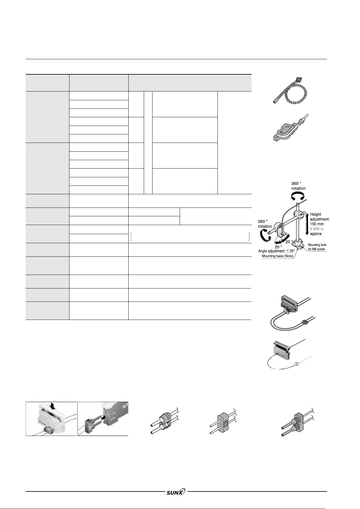
Fiber bender
Universal sensor
mounting stand
(Note 2)
Fiber cutter
Attachment for fixedlength fiber
)
)
Model No. Description
FTP-500 (0.5 m 1.640 ft)
FTP-1000 (1 m 3.281 ft)
FTP-1500 (1.5 m 4.921 ft)
FTP-N500 (0.5 m 1.640 ft)
FTP-N1000 (1 m 3.281 ft)
FTP-N1500 (1.5 m
4.921 ft
FDP-500 (0.5 m 1.640 ft)
FDP-1000 (1 m 3.281 ft)
FDP-1500 (1.5 m 4.921 ft)
FDP-N500 (0.5 m 1.640 ft)
FDP-N1000 (1 m 3.281 ft)
FDP-N1500 (1.5 m
4.921 ft
FB-1
MS-AJ1-F
MS-AJ2-F
FX-CT2
FX-CT1
FX-AT2
For
M4
thread
For
M3
thread
)
For
M6
thread
For
M4
thread
)
The fiber bender bends the sleeve part of the fiber head at the
proper radius. (Note 1)
Horizontal mounting type
Vertical mounting type
The free-cut type fiber can be easily cut.
Accessory. Does not attach with the FT-N8/NB8 or the
FD-N8/N4. (Note 3)
This is the attachment for the fixed length fiber. (
FT-B8
FT-NB8
FT-FM2
FT-FM2S
FT-FM2S4
FT-T80
FT-NFM2
FT-NFM2S
FT-NFM2S4
FD-B8
FD-FM2
FD-FM2S
Applicable fibers
FD-FM2S4
FD-N8
FD-T80
FD-N4
FD-NFM2
FD-NFM2S
FD-NFM2S4
FT-N8
FT-P80
FT-P60
FT-H13-FM2
FT-P40
FD-T40
FD-P40
FD-P80
FD-H13-FM2
Mounting stand assembly for fiber
(For M3, M4 or M6 threaded head fiber)
The protective
tube, made of
non-corrosive
stainless steel,
protects the
inner fiber cable
from any
external forces.
Accessory
)
Protective tube
• FTP-
• FDP-
Fiber bender
• FB-1
Universal sensor mounting stand
• MS-AJ1-F
• MS-AJ2-F
Using the arm which enables adjustment
in the horizontal direction, sensing can
also be done from above an assembly line.
Attachment for "2.2 mm
"0.087 in fiber
Attachment for "1 mm
"0.039 in fiber
Attachment for "1.3 mm
"0.051 in fiber
Attachment for "1 mm
"0.039 in / "1.3 mm
"0.051 in mixed fiber
Notes: 1) Do not bend the sleeve part of any side-view type fiber or ultra-small diameter head type fiber.
Notes: 2) Refer to p.332l for details of the universal sensor mounting stand.
Notes: 3) A conventional FX-CT1 fiber cutter is attached with the FT-P80 and the FD-P80.
Notes: 4) The conventional FX-AT10 fiber attachment is attached with the FD-N4.
FX-AT3
FX-AT4
FX-AT5
FX-AT6
This is the attachment for the "2.2 mm "0.087 in fiber.
Accessory. Does not attach with the FT-N8/NB8/P80 or the FD-N8/P80
(
This is the attachment for the "1 mm "0.039 in fiber
(Accessory. Does not attach with the FD-N4.) (Note 4)
This is the attachment for the "1.3 mm "0.051 in fiber (Accessory)
This is the attachment for the "1 mm"0.039 in / "1.3 mm
"0.051 in mixed fiber. (Accessory)
Note:
.)
Fiber cutter
• FX-CT2
• FX-CT1
The above figure is MS-AJ1-F.
The mounting base of MS-AJ2-F
has a different shape.
Fiber attachment
It’s possible to simultaneously cut two fibers to the same length
Each fiber (with some exceptions) has a newly developed two-in-one fiber attachment (FX-AT3/AT4/AT5/AT6) which enables two fibers to be cut simultaneously
to the same length with the new fiber cutter (FX-CT2). Also, since the fibers can be attached to the amplifier while being fixed in position in the two-in-one fiber
attachment, sensitivity changes resulting from variation in the amount of fiber insertion do not occur.
FX-AT2 FX-AT3
FX-AT4/AT5/AT6
82
Page 16
FX-301
08/2005
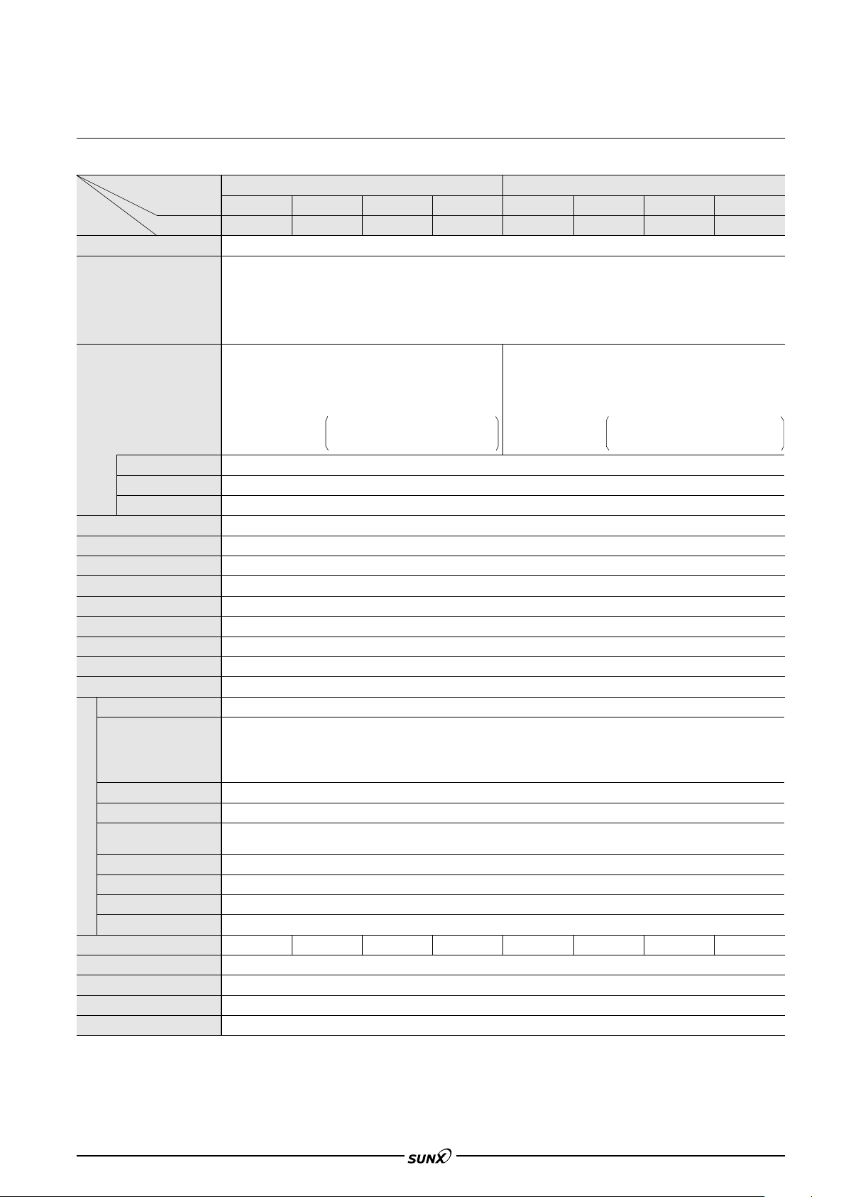
SPECIFICATIONS
Amplifiers
Type
Red LED Blue LED Green LED Infrared LED Red LED Blue LED Green LED
Item
Supply voltage
Model No.
FX-301 FX-301B FX-301G FX-301H FX-301P FX-301BP FX-301GP FX-301HP
<Red LED / Infrared LED type>
Normal operation: 960 mW or less
Power consumption
Output
Utilization category
Output operation
Short-circuit
protection
Response time
Sensitivity setting
Operation indicator
Stability indicator
MODE indicator
Digital display
Fine sensitivity adjustment function
Timer function
Automatic interference prevention function
Pollution degree
Ambient temperature
Ambient humidity
Ambient illuminance
EMC
Voltage withstandability
Environmental resistance
Insulation resistance
Vibration resistance
Shock resistance
Emitting element (modulated)
Material
Connecting method
Cable extension
Weight
Notes: 1) When the power supply is switched on, the emission timing are automatically set for interference prevention.
Notes: 2) The voltage withstandability and the insulation resistance values given in the above table are for the amplifier only.
Notes: 3) The cable for amplifier connection is not supplied as an accessory. Make sure to use the optional quick-connection cable given below.
Main cable (3-core): CN-73-C1 (cable length 1 m 3.281 ft), CN-73-C2 (cable length 2 m 6.562 ft), CN-73-C5 (cable length 5 m 16.404 ft)
Sub cable (1-core): CN-71-C1 (cable length 1 m 3.281 ft), CN-71-C2 (cable length 2 m 6.562 ft), CN-71-C5 (cable length 5 m 16.404 ft)
ECO mode: 600 mW or less
NPN open-collector transistor
65 !s or less (ultra high speed), 150 !s or less (FAST), 250 !s or less [STD / S-D (Red LED type only)], 2 ms or less (LONG) selectable with jog switch
Incorporated with variable ON-delay / OFF-delay / ONE SHOT timer, switchable either effective or ineffective. (timer period: 0.5 to 500 ms approx.)
Red LED Blue LED Green LED Infrared LED Red LED Blue LED Green LED
Current consumption 25 mA or less at 24 V
()( )
supply voltage
Maximum sink current:100 mA
•
Applied voltage:
•
Residual voltage: 1.5 V or less
•
Sunlight: 10,000?x at the light-receiving face, Incandescent light: 3,000?x at the light-receiving face
20 MΩ, or more, with 250 V DC megger between all supply terminals connected together and enclosure (Note 2)
NPN output PNP output
12 to 24 V DC10 % Ripple P-P 10 % or less
<Blue LED / Green LED type>
Current consumption 40 mA or less at
()
24 V supply voltage
50 mA, if five, or more, amplifiers
()()
are connected in cascade.
30 V DC or less (between output and 0 V)
at 100 mA (at 50 mA, if five, or more,
amplifiers are connected in cascade)
sink current.
Selectable either Light-ON or Dark-ON, with jog switch
2-level teaching / Limit teaching / Manual adjustment / Full auto-teaching (excluding red LED type)
Orange LED (lights up when the output is ON)
Green LED (lights up under stable light received condition or stable dark condition)
RUN: Green LED, TEACH ADJ L/D ON TIMER PRO: Yellow LED
4 digit red LED display
Incorporated (Up to four sets of fiber heads can be mounted close together) (Note 1)
3 (Industrial environment)
Normal operation: 720 mW or less
ECO mode: 430 mW or less
PNP open-collector transistor
DC-12 or DC-13
Incorporated
Incorporated
Current consumption 18 mA or less at 24 V
supply voltage
• Maximum source current: 100 mA
•
Applied voltage: 30 V DC or less (between output and V)
• Residual voltage: 1.5 V or less
Current consumption 30 mA or less at
()
24 V supply voltage
50 mA, if five, or more, amplifiers
are connected in cascade.
at 100 mA (at 50 mA, if five, or more,
amplifiers are connected in cascade)
source current.
10 to 55 °C 14 to 131 °F
If 4 to 7 units are connected in cascade:
if 8 to 16 units are connected in cascade:
(No dew condensation or icing allowed),
20 to 70 °C 4 to 158 °F
Storage:
35 to 85 % RH, Storage: 35 to 85 % RH
Red LED type: EN 50081-2, EN 50082-2, EN 60947-5-2
Blue / green / infrared LED type: EN 60947-5-2
1,000 V AC for one min. between all supply terminals connected together and enclosure (Note 2)
10 to 150 Hz frequency, 0.75 mm 0.030 in amplitude in X, Y and Z directions for two hours each
2
acceleration (10 G approx.) in X, Y and Z directions for five times each
98 m/s
Enclosure: Heat-resistant ABS, Case cover: Polycarbonate, Switch: Acrylic
Connector (Note 3)
Extension up to total 100 m 328.084 ft is possible with 0.3 mm
10 to 50 °C 14 to 122 °F,
10 to 45 °C 14 to 113 °F
25 g approx.
2
, or more, cable.
)(
Infrared LED
Infrared LED
83
Page 17
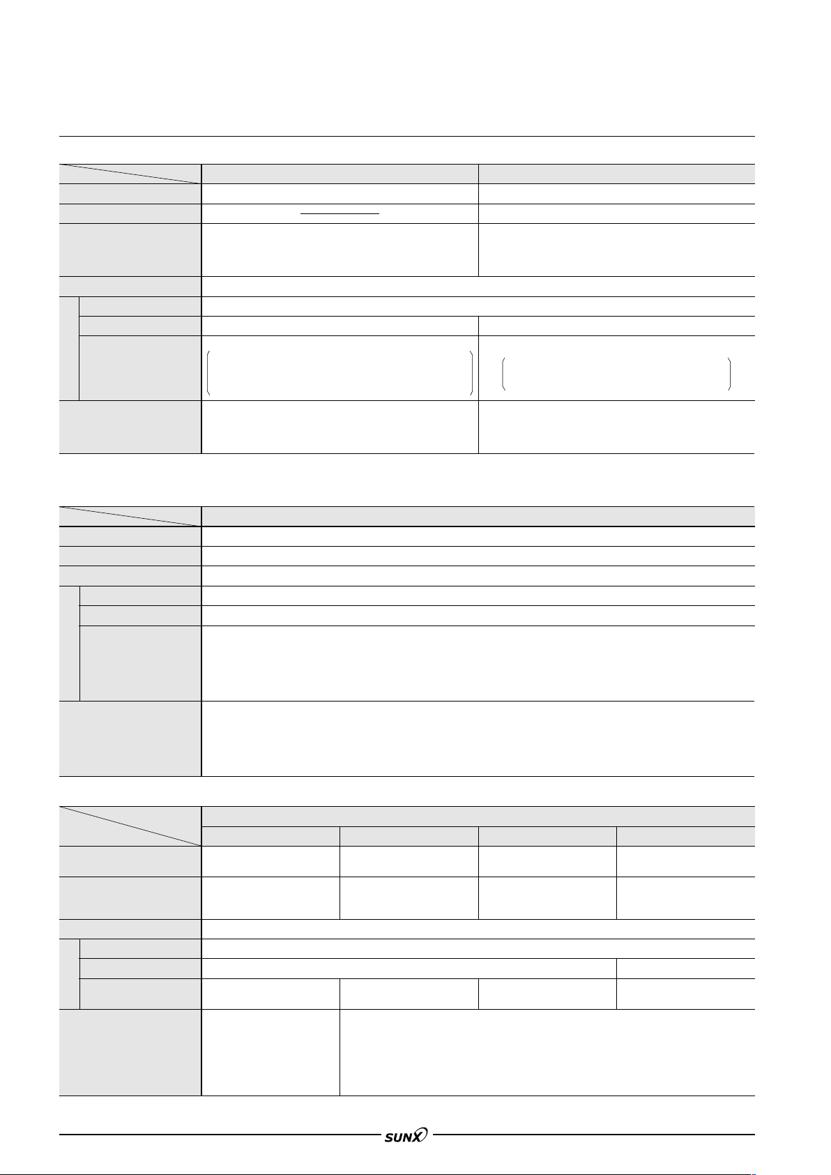
FX-301
08/2005
SPECIFICATIONS
Fibers
Item
Allowable bending radius
Bending durability
Ambient temperature
Ambient humidity
Fiber core
Sheath
Material
Fiber head
Accessories (Note 2)
Notes: 1) Sleeve part of side-view fiber cannot be bent.
Notes: 2) The five types of attached fiber attachments (FX-AT2/AT3/AT4/AT5/AT6) described in this catalog are for use only with the FX-301/311 series. Refer to
p.82 for details ‘FIBER OPTIONS’. Fiber attachment accessories are also supplied along with conventional amplifiers. Please contact our office for more
details on these accessories.
Item
Allowable bending radius
Ambient temperature
Ambient humidity
Fiber core
Sheath
Material
Fiber head
Accessories (Note)
Note:
The five types of attached fiber attachments (FX-AT2/AT3/AT4/AT5/AT6) described in this catalog are for use only with the FX-301/311 series. Refer to p.82 for details ‘FIBER
OPTIONS’. Fiber attachment accessories are also supplied along with conventional amplifiers. Please contact our office for more details on these accessories.
Item Wide beam Array Narrow beam High precision
Allowable bending radius
Ambient temperature
Ambient humidity
Fiber core
Sheath
Material
Fiber head
Accessories (Note)
Note:
The five types of attached fiber attachments (FX-AT2/AT3/AT4/AT5/AT6) described in this catalog are for use only with the FX-301/311 series. Refer to p.82 for details ‘FIBER
OPTIONS’. Fiber attachment accessories are also supplied along with conventional amplifiers. Please contact our office for more details on these accessories.
Type
R25 mm R0.984 in or more [Sleeve of a head with sleeve:R10 mm R0.394 in or more (Note 1)]
40 to 70 °C 40 to 158 °F
FT-SFM2SV2: 20 to 70 °C 4 to 158 °F
FT-V22, FD-SFM2SV2:
()
FT-V41, FD-V41, FT-V10:
Polyethylene (FT-V22: Polyolefin)
FT-SFM2L/T80/SFM2/SNFM2/SFM2SV2/V22/V41,
FD-T80/T40/S80/SNFM2/SFM2SV2/V41 and Sleeve: Stainless steel (SUS)
FT-FM10L: ABS, Lens of FT-FM10L/SFM2L/V10: Acrylic
FT-V10: Stainless steel (SUS) and Polycarbonate
All fibers (except for FT-NB8/N8 and FD-N8/N4): 1 fiber attachment set
Free-cut type fibers (except for FT-NB8/N8 and FD-N8/N4): FX-CT2 (fiber cutter) 1 pc.
Threaded head fibers: Nuts 2 pcs. (thru-beam type: 4 pcs.) and toothed lock washer
1 pc. (thru-beam type: 2 pcs.)
Type
R1 mm R0.039 in or more (FD-WG4/WSG4: R2 mm R0.079 in or more, Sleeve of FD-W44: R10 mm R0.394 in or more)
Standard Flexible
R4 mm R0.157 in or more
1 million times or more (at R10 mm R0.394 in, FT-P40/P2 and FD-P40/P2: at R4 mm R0.157 in)
40 to 70 °C 40 to 158 °F
20 to 60 °C 4 to 140 °F
40 to 60 °C 40 to 140 °F
35 to 85%RH (No dew condensation or icing allowed)
Acrylic
Brass (Nickel plated)
Sharp bending
FT-Z8, FT-P60, FT-PS1, FD-P60, FD-P50:
()
40 to 60 °C 40 to 140 °F
Vinyl chloride (FT-PS1: Polyethylene, FD-P2:Vinyl chloride and Polyurethane)
FT/FD-P80, FT-P60: Brass (Nickel plated)
Case of FT-Z8: Polycarbonate
Lens of FT-Z8H/Z8E, Front film of FT-Z8: Polyester
All fibers: 1 fiber attachment set. (except for FT-P80 and FD-P80)
Free-cut type fibers: FX-CT2 (fiber cutter) 1 pc.
Threaded head fibers: Nuts 2 pcs. (thru-beam type: 4 pcs.) and toothed lock
washer 1 pc. (thru-beam type: 2 pcs.), FT-Z8: 1 set of mounting screw
Stainless steel (SUS)
(FT/FD-P80: FX-CT1 1 pc.)
40 to 60 °C 40 to 140 °F (FT-WA30/WA8/WKV8: 40 to 55 °C 40 to 131 °F)
35 to 85 %RH (No dew condensation or icing allowed)
Acrylic
Polyethylene
FT-W8/W4, FD-W8/W44/WG4: Brass (Nickel plated)
Case of FT-WA30/WA8/WZ8, Lens of FT-WS8L and Resin part of FT-WKV8: Polycarbonate, Lens of FT-WA30: Norbornene resin
Lens of FT-WA8: Polyolefin, Lens of FT-WZ8H/WZ8E, Reflector of FT-WZ8E and Prism of FT-WKV8: Acrylic,
Reflector of FT-WZ8: Polycarbonate, FD-WL41: Heat-resistant ABS, Front film of FD-WL41: Polyester,
( )
FD-WL42: Aluminum (Black ALMITE), Lens of FD-WKZ1: Optical lens
All fibers: 1 fiber attachment set and FX-CT2 (fiber cutter) 1 pc.
Threaded fibers: Nuts 2 pcs. (thru-beam type: 4 pcs.) and toothed lock washer 1 pc. (thru-beam type: 2 pcs.)
FT-WA30: 0.5
FT-WA8: 0.5
FT-WZ8: 1 set of mounting screw
FD-WKZ1: mounting bracket 1 pc.
Type Special use
FT-A30/A8: R10 mm R0.394 in or more
FD-A15: R25 mm R0.984 in or more
FT-A30, FD-A15:40 to 60 °C 40 to 140 °F
FT-A8:40 to 70 °C 40 to 158 °F
Lens of FT-A30, FD-A15: Norbornene resin
() )
Lens of FT-A8: Polyolefin
All fibers: 1 fiber attachment set and
FT-A30: 0.532 mm 0.0201.260 in
FT-A8:0.512 mm 0.0200.472 in
32 mm 0.0201.260 in seal type slit mask 2 pcs.
12 mm 0.0200.472 in seal type slit mask 2 pcs. and 112 mm 0.0390.472 in seal type slit mask 2 pcs.
Polycarbonate
FX-CT2 (fiber cutter) 1 pc.
seal type slit mask 2 pcs.
seal type slit mask 2 pcs. and
112 mm 0.0390.472 in
seal type slit mask 2 pcs.
Stainless steel (SUS) (including sleeve)
R25 mm R0.984 in or more
40 to 70 °C
40 to 158 °F
35 to 85 %RH (No dew condensation or icing allowed)
Polyethylene
Brass (Nickel plated)
All fibers: 1 fiber attachment set
Free-cut type fibers: FX-CT2 (fiber cutter) 1 pc.
Threaded head fibers: Nuts 2 pcs. and toothed lock washer 1 pc.
R25 mm R0.984 in or more
(FT-KV1: R10 mm R0.394 in or more)
40 to 60 °C
40 to 140 °F
Acrylic
Stainless steel (SUS), Polycarbonate
Lens: Norbornene resin
(
Lens of FT-KV1: Polycarbonate, Prism of FT-KV8: Acrylic
FD-EG2/EG3: R10 mm R0.394 in or more
FD-G4/G6/EG1: R25 mm R0.984 in or
20 to 60°C 4 to 140 °F
FD-G4:40 to 70 °C 40 to 158 °F
()
40 to 60 °C 40 to 140 °F
FD-G6:
Polyolefin (FD-G4/G6: Polyethylene)
Brass (Nickel plated)
[FD-G6: Stainless steel (SUS)]
more
84
Page 18
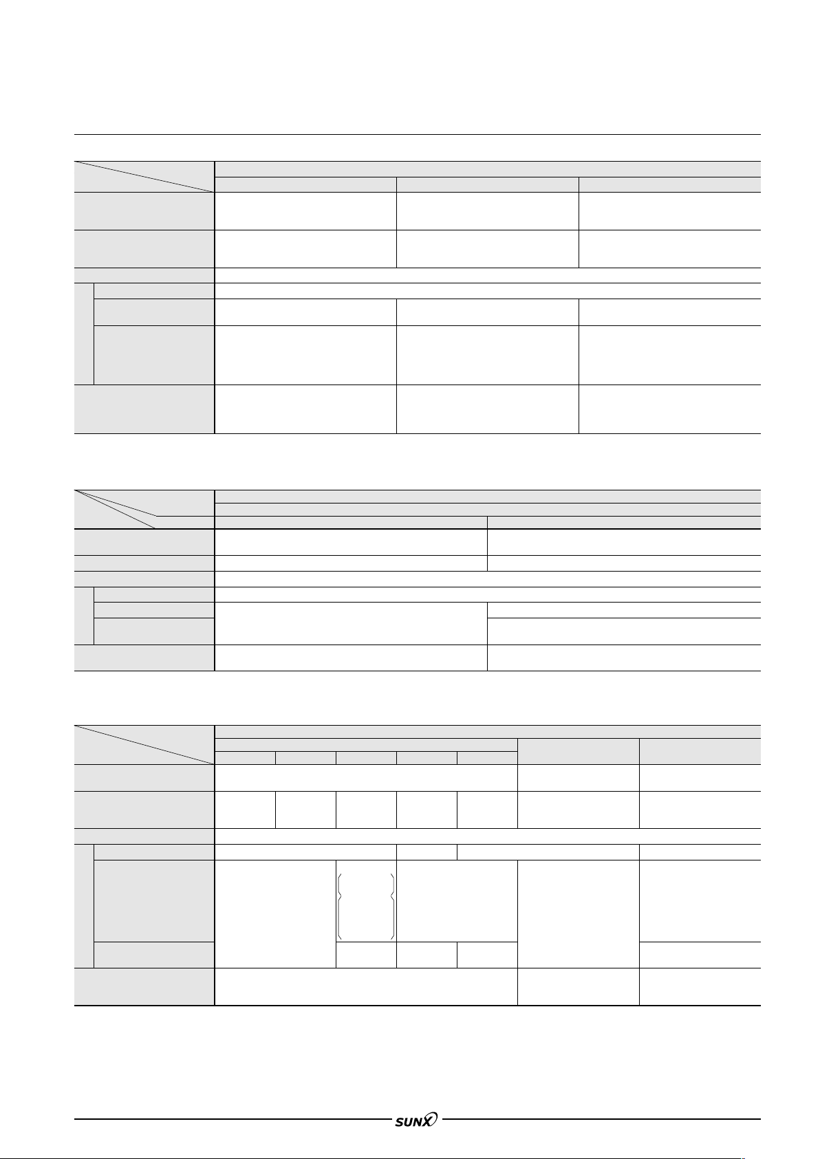
FX-301
08/2005
SPECIFICATIONS
Fibers
Item Ultra-small diameter Fixed-focus reflective Tough flexible
Allowable bending radius
Ambient temperature
Ambient humidity
Fiber core
Sheath
Material
Fiber head
Accessories (Note 2)
Notes: 1) Sleeve part cannot be bent.
Notes: 2)
The five types of attached fiber attachments (FX-AT2/AT3/AT4/AT5/AT6) described in this catalog are for use only with the FX-301/311 series. Refer to p.82 for details ‘FIBER
OPTIONS’. Fiber attachment accessories are also supplied along with conventional amplifiers. Please contact our office for more details on these accessories.
Type
FT-E12/E22: R5 mm R0.197 in or more (Note 1)
FD-E12: R10 mm R0.394 in or more (Note 1)
FD-E22/EN500S1/ENM1S1: R25 mm R0.984 in or more (Note 1)
FT-E12/E22, FD-E22:40 to 70 °C 40 to 158 °F
FD-E12:40 to 60 °C 40 to 140 °F
FD-EN500S1/ENM1S1:20 to 60 °C 4 to 140 °F
Polyolefin
Brass (Nickel plated)
[Sleeve: Stainless steel (SUS)]
All fibers: 1 fiber attachment set
Threaded head fibers: Nuts 2 pcs. and
toothed lock washer 1 pc.
(FD-L43: R4 mm R0.157 in or more)
FD-L43: 0 to
FD-L41/L42:40 to 60 °C 40 to 140 °F
FD-L4:40 to 70 °C 40 to 158 °F
35 to 85 %RH (No dew condensation or icing allowed)
Polyethylene (FD-L42: Vinyl chloride)
FD-L43/L41: Heat-resistant ABS
FD-L4: ABS
FD-L42: Aluminum (Black ALMITE)
All fibers: 1 fiber attachment set and
FX-CT2 (fiber cutter) 1 pc.
FD-L4: M2.6 (length 12 mm 0.472 in)
screws with washers 2 pcs. and nuts 2 pcs.
Special use
R10 mm R0.394 in or more
70 °C 32 to 158 °F
Acrylic
Lens of FD-L43/L4: Acrylic
()
Front film of FD-L41: Polyester
R10 mm R0.394 in or more
40 to 60 °C 40 to 140
(FD-P81X:
Polyethylene [FT-P81X: Vinyl chloride,
Protective tube: Stainless steel (SUS)]
FT-P81X, FD-P81X: Brass (Nickel plated)
FD-G6X: Stainless steel (SUS)
All fibers: 1 fiber attachment set , nuts 2
pcs. (thru-beam type: 4 pcs.) and toothed
lock washer 1 pc. (thru-beam type: 2 pcs.)
FD-G6X: FX-CT2 (fiber cutter) 1 pc.
40 to 70 °C 40 to 158 °F)
°F
Ty p
e
Item Model No.
Allowable bending radius
Ambient temperature
Ambient humidity
Fiber core
Sheath
Material
Fiber head
Accessories (Note 2)
Notes: 1) With the liquid sensing fiber, make sure that the temperature of the liquid is also within the ambient temperature range.
Notes: 2)
The five types of attached fiber attachments (FX-AT2/AT3/AT4/AT5/AT6) described in this catalog are for use only with the FX-301/311 series. Refer to p.82 for details ‘FIBER
OPTIONS’. Fiber attachment accessories are also supplied along with conventional amplifiers. Please contact our office for more details on these accessories.
Protective tube: R40 mm R1.575 in or more
Fiber: R15 mm R0.591 in or more
40 to 125 °C 40 to 257 °F (Note 1)
Polypropylene
(Protective tube: Fluorine resin)
FD-F8Y FD-F4/F9
35 to 85 %RH (No dew condensation or icing allowed)
1 fiber attachment set
FX-CT2 (fiber cutter) 1 pc.
Special use
Liquid level sensing
Polycarbonate
R10 mm R0.394 in or more
40 to 100 °C 40 to 212 °F (Note 1)
Polyethylene
Polyetherimide
(Lens: Polycarbonate)
1 fiber attachment set, FX-CT2 (fiber cutter) 1pc.
Tying bands 4 pcs., anti-slip tubes 2 pcs.
Environment resistant
Type Heat-resistant
Item
Allowable bending radius
350 °C 662 °F type
(FT-H20W-: R10 mm R0.394 in or more, Sleeve of a head with sleeve: R10 mm R0.394 in or more)
60 to 350 °C
Ambient temperature
Ambient humidity
Fiber core
Sheath
Material
Fiber head
Accessories (Note 5)
Notes: 1)
Notes: 2)
Notes: 3) If the fiber material is quartz glass or multi-component glass, keep it away from vibration or impact.
Notes: 4) The normal temperature for continuous usage or storage should be
Notes: 5)
If the fiber is used below 30 °C 22 °F, its maximum resistable temperature drops to 200° C 392 °F. If the side-view lens FX-SV1 is put on the fiber head,
the allowable maximum temperature drops to
The ambient temperature of heat-resistant 350 °C 662 °F type, 300 °C 572 °F type, 200 °C 392 °F type and 180 °C 356 °F type fibers are the value in dry
condition. In humid environment, the ambient temperature differs. (For a high humidity of 85 %RH, the ambient temperature is 0 to
The five types of attached fiber attachments (FX-AT2/AT3/AT4/AT5/AT6) described in this catalog are for use only with the FX-301/311 series. Refer to p.82 for details ‘FIBER
OPTIONS’. Fiber attachment accessories are also supplied along with conventional amplifiers. Please contact our office for more details on these accessories.
76 to 662 °F
(Note 1, 2)
Stainless steel (SUS)
FT-H20W-, FD-H18-L31 and FT-H13-FM2: 1 fiber attachment set
Free-cut type fibers: FX-CT2 (fiber cutter) 1 pc.
Threaded head fibers: Nuts 2 pcs. (thru-beam type: 4 pcs.) and toothed lock washer 1 pc. (thru-beam type: 2 pcs.)
300°C 572°F type 200°C 392°F type 180°C 356°F type 130°C 266°F type
R25 mm R0.984 in or more
60 to 300 °C
76 to 572 °F
(Note 1, 2, 3)
Multi-component glass (Note 3) Silicone Acrylic Quartz glass (Note 3)
60 to 200 °C
76 to 392 °F
(Note 2)
Silicone
Inside stainless steel
(SUS) spiral tube
FD-H20-21:
Stainless steel (sus)
FT-H20W-:
Fluorine resin
Brass (Nickel plated)
FD-H20-21: Stainless steel (sus)
300 °C 572 °F. (The ambient temperature range of FX-SV1 is from 60 to 300 °C 76 to 572 °F.)
60 to 180 °C
76 to 356 °F
(Note 2, 4)
35 to 85 %RH (No dew condensation or icing allowed)
Stainless steel (SUS)
60 to 130 °C
76 to 266 °F
Fluorine resin
Brass (Nickel plated)
60 to 150 °C 76 to 302 °F.
Chemical-resistant Vacuum
R30 mm R1.181 in or more
(FT-Z802Y: R25 mm R0.984 in or more)
40 to 115 °C
40 to 239 °F
(FT-Z802Y: 0 to 60 °C 14 to 140 °F)
Protective tube: Fluorine resin
Sheath: Polypropylene
(Sheath of FT-Z802Y: Fluorine resin)
1 fiber attachment set
FX-CT2 (fiber cutter) 1 pc.
R200 mm R7.874 in or more
(FT-60V: R30 mm R1.181 in or more)
40 to 120 °C
40 to 248 °F
Fluorine resin
Aluminum
Nuts 2 pcs. (thru-beam type: 4
pcs.) and toothed lock washer
1 pc. (thru-beam type: 2 pcs.)
40 °C 14 to 104 °F.)
85
Page 19
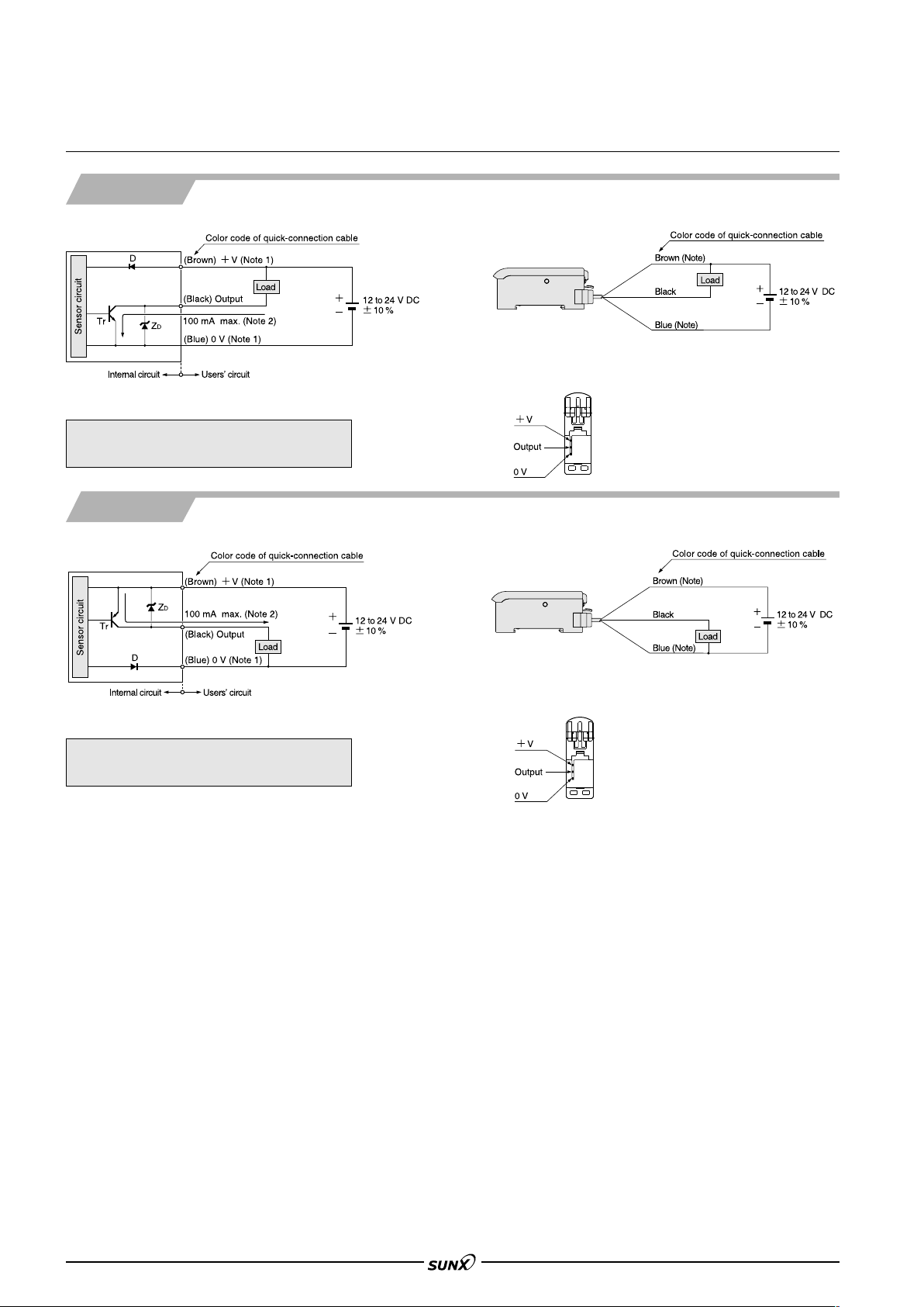
FX-301
08/2005
I/O CIRCUIT AND WIRING DIAGRAMS
NPN output type
I/O circuit diagram Wiring diagram
Note: The quick-connection sub cable does not have brown lead wire
and blue lead wire.
Notes: 1)
The quick-connection sub cable does not have V (brown) and 0 V (blue)
Notes: 2) 50 mA max., if five amplifiers, or more, are connected together.
Terminal arrangement diagram
.
Symbols … D : Reverse supply polarity protection diode
D: Surge absorption zener diode
Z
Tr : NPN output transistor
PNP output type
I/O circuit diagram Wiring diagram
Note: The quick-connection sub cable does not have brown lead wire
and blue lead wire.
Notes: 1)
The quick-connection sub cable does not have V (brown) and 0 V (blue)
Notes: 2) 50 mA max., if five amplifiers, or more, are connected together.
Symbols … D : Reverse supply polarity protection diode
D: Surge absorption zener diode
Z
Tr : PNP output transistor
Terminal arrangement diagram
.
86
Page 20
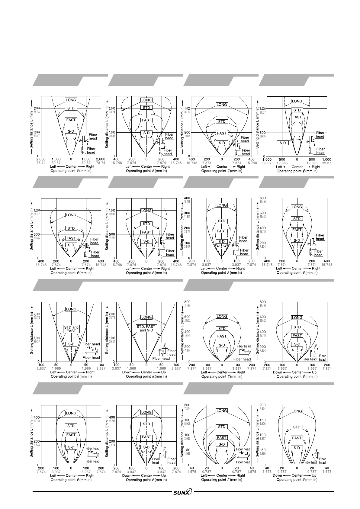
SENSING CHARACTERISTICS (TYPICAL)
L
08/2005
Parallel deviation
FX-301
FT-FM10L FT-SFM2L FT-B8 FT-NB8
FT-FM2 FT-FM2S FT-FM2S4
FT-T80 FT-SFM2
Thru-beam type Thru-beam type Thru-beam type Thru-beam type
Thru-beam type Thru-beam type Thru-beam type Thru-beam type
FT-N8
FT-NFM2 FT-NFM2S
FT-NFM2S4 FT-SNFM2
FT-R80
FT-V10
Horizontal direction
FT-V22 FT-V41
Horizontal direction
Thru-beam type Thru-beam type
Vertical direction Horizontal direction Vertical direction
Thru-beam type Thru-beam type
Vertical direction
Horizontal direction Vertical direction
FT-SFM2SV2
87
Page 21

FX-301
L
08/2005
SENSING CHARACTERISTICS (TYPICAL)
Parallel deviation
FT-WA30
FT-A30
Horizontal direction
Thru-beam type Thru-beam type
Vertical direction
FT-WA8
FT-A8
Horizontal direction
Vertical direction
FT-WZ8H FZ-WZ8E
Horizontal direction
FT-WZ8
Thru-beam type Thru-beam type
Vertical direction
Thru-beam type
Horizontal direction
FT-WKV8
Horizontal direction
Vertical direction
Thru-beam type
Vertical direction
FT-WS8L
88
Thru-beam type Thru-beam type Thru-beam type
FT-W8
FT-WS8
FT-WS3
FT-W4
FT-WS4
Thru-beam type
Page 22

L
SENSING CHARACTERISTICS (TYPICAL)
08/2005
Parallel deviation
FX-301
FT-WV42
Horizontal direction Vertical direction
FT-Z8 FT-P80 FT-P60 FT-P40
Thru-beam type
Thru-beam type Thru-beam type Thru-beam type Thru-beam type
FT-Z8H FT-Z8E
Thru-beam type Thru-beam type
FT-P2 FT-PS1
FT-AFM2E
Horizontal direction Vertical direction
Thru-beam type Thru-beam type
Thru-beam type
FT-AFM2
Horizontal direction Vertical direction
FT-K8
Thru-beam type
Thru-beam type
89
Page 23

FX-301
08/2005
SENSING CHARACTERISTICS (TYPICAL)
Parallel deviation
FT-KV1
Horizontal direction Vertical direction
FT-KV8
Horizontal direction Vertical direction
Thru-beam type
Thru-beam type
FT-E12 FT-E22
Thru-beam type Thru-beam type
FT-P81X
FT-H13-FM2 FT-L8Y
Thru-beam type Thru-beam type Thru-beam type Thru-beam type
Thru-beam type Thru-beam type
FT-H35-M2
FT-H35-M2S6
FT-H20W-M1
FT-H20W-M2
FT-V8Y
Horizontal direction Vertical direction
Thru-beam type
FT-H20-M1
90
Page 24

SENSING CHARACTERISTICS (TYPICAL)
08/2005
Parallel deviation
FX-301
FT-Z802Y FT-6V FT-60V
Parallel deviation with FX-LE1 (expansion lens) applied on both sides
FT-B8 FT-W8 FT-P80 FT-H35-M2
Thru-beam type Thru-beam type Thru-beam type
Thru-beam type Thru-beam type Thru-beam type Thru-beam type
FT-H20W-M2
Parallel deviation with FX-LE2 (super-expansion lens) applied on both sides
FT-B8 FT-W8 FT-P80 FT-H35-M2
Thru-beam type
Thru-beam type Thru-beam type Thru-beam type
FT-H20-M1
Thru-beam type
Thru-beam type
91
Page 25

FX-301
08/2005
SENSING CHARACTERISTICS (TYPICAL)
Parallel deviation with FX-LE2 (super-expansion lens) applied on both sides
FT-H20W-M2
Parallel deviation with FX-SV1 (side-view lens) applied on both sides
FT-B8
Horizontal direction Vertical direction
Thru-beam type Thru-beam type Thru-beam type
Thru-beam type
FT-H20-M1 FT-H13-FM2
FT-W8
Horizontal direction
Thru-beam type
Vertical direction
FT-P80
Horizontal direction Vertical direction Horizontal direction Vertical direction
FT-H20W-M2
Horizontal direction Vertical direction Horizontal direction Vertical direction
Thru-beam type
Thru-beam type
FT-H35-M2
FT-H20-M1
Thru-beam type
Thru-beam type
92
Page 26

SENSING CHARACTERISTICS (TYPICAL)
08/2005
Sensing fields
FD-B8
Reflective type Reflective type Reflective type Reflective type
FD-5
FD-FM2
FD-T80 FD-S80
FD-FM2S FD-FM2S4
FX-301
FD-T40 FD-NFM2
FD-NFM2S FD-NFM2S4
FD-SNFM2
FD-N8 FD-N4
FD-SFM2SV2
Horizontal direction Vertical direction
Reflective type Reflective type
Reflective type
FD-R80
FD-V41
Horizontal direction Vertical direction
Reflective type
Reflective type
FD-WKZ1
Horizontal direction Vertical direction
Reflective type
FD-W8 FD-WT8
FD-WS8
Reflective type Reflective type
FD-W44
FD-WT4
93
Page 27

FX-301
08/2005
SENSING CHARACTERISTICS (TYPICAL)
Sensing fields
FD-WG4
FD-WSG4
Reflective type
FD-WV42
Horizontal direction Vertical direction
Reflective type
FD-P80
Reflective type
FD-P60 FD-P50
FD-A15
Horizontal direction Vertical direction
Reflective type Reflective type
Reflective type
FD-P40
FD-AFM2
FD-AFM2E
Horizontal direction Vertical direction
Reflective type
Reflective type
FD-P2
Reflective type
FD-G4 FD-G6
Reflective type Reflective type
94
FD-EG1 FD-EG2
Reflective type Reflective type
Page 28

SENSING CHARACTERISTICS (TYPICAL)
08/2005
Sensing fields
FX-301
FD-EG3
FD-ENM1S1 FD-P81X
Reflective type
Reflective type Reflective type
FD-E12
Reflective type
FD-E22
FD-G6X
Reflective type
Reflective type
FD-EN500S1
FD-H35-M2
FD-H35-M2S6
Reflective type
Reflective type
FD-H20-M1 FD-H35-20S
FD-H13-FM2 FD-6V
Reflective type Reflective type
Reflective type Reflective type
FD-H20-21
Reflective type
FD-H30-L32
FD-H18-L31
Reflective type
95
Page 29

FX-301
08/2005
PRECAUTIONS FOR PROPER USE
Amplifier
This product is not a safety sensor. Its use is not
intended or designed to protect life and prevent body
injury or property damage from dangerous parts of
machinery. It is a normal object detection sensor.
Mounting
How to mount the amplifier
1 Fit the rear part of the amplifier on
a 35 mm 1.378 in width DIN rail.
2
Press down the front part of the
mounting section of the amplifier on
35 mm 1.378 in width DIN rail
the 35 mm 1.378 in width DIN rail.
How to remove the amplifier
1 Push the amplifier forward.
2 Lift up the front part of the
amplifier to remove it.
Note: Take care that if the front part is lifted without pushing the amplifier
forward, the hook on the rear portion of the mounting section is likely to
break.
How to connect the fiber cables
1
Snap the fiber lock lever down.
2
Insert fiber cables slowly into the
inlets until they stop. (Note 1)
3 Return the fiber lock lever
to the original position, till
it stops.
Notes: 1) In case the fiber cables are not inserted to a position where they
stop, the sensing range reduces.
Notes: 2) With the coaxial reflective type fiber, such as, FD-G4 or FD-FM2,
insert the single-core fiber cable into the beam-emitting inlet and
the multi-core fiber cable into the beam-receiving inlet. If they are
inserted in reverse, the sensing accuracy will deteriorate.
Connection
• Make sure that the power supply is off while connecting
or disconnecting the quick-connection cable.
Connection method
1 Holding the connector of the
quick-connection cable, align its
projection with the groove at
the top portion of the amplifier
connector.
2 Insert the connector till a click
is felt.
Disconnection method
1
Pressing the projection at the top of
the quick-connection cable connector,
pull out the connector.
Take care that it the connector is pulled out
Note:
without pressing the projection, the projection
may break. Do not use a quick-connection
cable whose projection has broken.
Note:
Further, do not pull by holding the cable, as
this can cause a cable-break.
Cascading amplifiers
•
Make sure that the power supply is off while cascading or removing the amplifier.
•
Make sure to check the allowable ambient temperature, as it
depends on the number of amplifiers connected in cascade.
•
In case two, or more, amplifiers are connected in cascade,
make sure to mount them on a DIN rail.
•
When connecting in cascade, mount the amplifiers close to each other, fitting
them between the optional end plates (MS-DIN-E) mounted at the two ends.
• When the amplifiers move on the DIN rail depending on
the attaching condition, fitting them between the optional
end plates (MS-DIN-E) mounted at the two ends.
• Up to maximum 15 amplifiers can be added (total 16
amplifiers connected in cascade.)
• When connecting more than two amplifiers in cascade,
use the sub cable (CN-71-C) as the quick-connection
cable for the second amplifier onwards.
• Between the FX-301B(P)/G(P)/H(P) and the FX-301(P),
the setting status copy function via communication signal
cannot be used. If coupling these, please arrange
identical models one at a time.
Cascading method
1 Mount the amplifiers, one by
one, on the 35 mm1.378 in
width DIN rail.
1
(For details, refer to ‘Mounting’.)
2
Slide the sub units next to the
main unit, and connect the
quick-connection cables.
3
Mount the optional end plates
(MS-DIN-E) at both the ends to
hold the amplifiers between
their flat sides.
4 Tighten the screws to fix the
end plates (MS-DIN-E).
Dismantling
1 Loosen the screws of the end
1 Loosen the screws of the end
plates (MS-DIN-E).
plates (MS-DIN-E).
2
2
Remove the end plates (MS-DIN-E).
Remove the end plates (MS-DIN-E).
3
Slide the sub units and remove
3
Slide the sub units and remove
them one by one.
them one by one.
3
(For details, refer to ‘Mounting’.)
3
(For details, refer to ‘Mounting’.)
Operation procedure
• When the power supply is switched on, communication
self-check is carried out and normal condition is
displayed [MODE indicator / RUN (green) lights up and
the digital display shows incident light intensity].
•
When MODE key is pressed, the mode changes as per the diagram below.
Part description
96
When jog switch is pressed, the setting is confirmed.
When MODE key is pressed for 2 sec., or more, the sensor returns to the RUN mode.
Cancellation is possible by pressing MODE key during setting.
Page 30

PRECAUTIONS FOR PROPER USE
08/2005
Amplifier
FX-301
Teaching
•
The threshold values can be set by 2-level teaching, limit teaching or fullauto teaching, when the MODE indicator / TEACH (yellow) lights up.
In case of 2-level teaching
•
This is the method of setting the threshold value by teaching two levels, corresponding to
the object present and object absent conditions. Normally, setting is done by this method.
Step
Set the fiber within the sensing
range.
Press MODE key to light up
1
MODE indicator / TEACH
(yellow).
Press jog switch in the object present condition.
If the teaching is accepted, the read incident light intensity blinks in the digital display.
Thru-beam type Reflective type
2
MODE indicator / TEACH (yellow) blinks.
Press jog switch in the object absent condition.
Thru-beam type Reflective type
3
If the teaching is accepted, the read incident light intensity
blinks in the digital display and the threshold value is set
at the mid-value between the incident light intensities in
the object present and the object absent conditions. After
this, the judgment on the stability of sensing is displayed.
4
• In case stable sensing is possible: ‘ ’ is displayed.
Stability indicator (green) blinks.
• In case stable sensing is not possible: ‘ ’ blinks.
Stability indicator (green) is off.
The threshold value is displayed.
5
‘ ’ blinks in the digital display.
6
The incident light intensity appears in the digital
7
display and the setting is complete.
Note: Do not move or bend the fiber cable after the sensitivity setting. Detection may become unstable.
In case of full auto-teaching
•
Full auto-teaching is used when it is desired to set the threshold value
Description Display
FX-301B(P)/G(P)/H(P) only
without stopping the assembly line, with the object in the moving condition.
Step
Set the fiber within the sensing
range.
Press MODE key to light up
1
MODE indicator / TEACH
(yellow).
Press the jog switch continuously for 0.5 sec. or more
with the object moving on the assembly line. (The
2
incident light intensity is displayed during sampling.)
‘ ’ is displayed on the digital display. Release the
3
jog switch when the object has passed.
If the teaching is accepted, the read incident light intensity
blinks in the digital display and the threshold value is set
at the mid-value between the incident light intensities in
the object present and the object absent conditions. After
this, the judgment on the stability of sensing is displayed.
4
• In case stable sensing is possible: ‘ ’ is displayed.
Stability indicator (green) blinks.
• In case stable sensing is not possible: ‘ ’ blinks.
Stability indicator (green) is off.
The threshold value is displayed.
5
‘ ’ blinks in the digital display.
6
The incident light intensity appears in the digital
7
display and the setting is complete.
Description Display
In case of limit teaching
•
This is the method of setting the threshold value by teaching
only the object absent condition (stable incident light
condition). This is used for detection in the presence of a
background body or for detection of small objects.
Step
Set the fiber within the sensing
range.
Press MODE key to light up
1
MODE indicator / TEACH
(yellow).
Press jog switch in the object absent condition.
If the teaching is accepted, the read incident light
intensity blinks in the display.
Thru-beam type Reflective type
2
MODE indicator / TEACH (yellow) blinks.
3
Turn jog switch to the ‘
If jog switch is turned to the ‘’ side, ‘ ’ scrolls
(twice) the display from right to left, and the threshold
level is shifted to a value approx. 15 %
higher (lower sensitivity) than that set
at 2. (Note 1)
This is used in case of reflective type fibers.
If jog switch is turned to the ‘’ side, ‘ ’ scrolls
(twice) the display from left to right, and the threshold
level is shifted to a value approx. 15 %
lower (higher sensitivity) than that set
4
at 2. (Note 1)
This is used in case of thru-beam type
fibers.
After this, the judgment on whether the setting shift
amount can be shifted or not is displayed.
5
• In case shifting is possible: ‘ ’ blinks.
• In case shifting is not possible: ‘ ’ blinks.
The threshold value is displayed.
6
‘ ’ blinks in the digital display.
7
The incident light intensity appears in the digital
8
display and the setting is complete.
Notes: 1) The approx. 15% amount of shift is the initial value. The amount of
shift can be changed in the PRO mode from approx. 5 to 80 %
(5 % step). Refer to the ‘Fiber Sensor Guide Book’ or ‘SUNX fiber
sensor home page’ (http://www.fiber-sensor.com) for more details
pertaining to setting instructions.
Notes: 2) Do not move or bend the fiber cable after the sensitivity setting.
Detection may become unstable.
Notes: 1) The threshold value’s shift amount can be selected in PRO mode.
Refer to the ‘SUNX fiber sensor home page’ (http://www.fibersensor.com) for more details pertaining to setting instructions.
(Increments of 5 % between –45 and 45 % for setting possible. 0 %
default.)
Notes: 2) Do not move or bend the fiber cable after the sensitivity setting.
Detection may become unstable.
Description Display
’ side or ‘’ side.
97
Page 31

FX-301
08/2005
PRECAUTIONS FOR PROPER USE
Amplifier
Threshold value fine adjustment Key-lock function
Step
Press MODE key to light up
MODE indicator / ADJ (yellow).
1
In case the threshold value is to be increased
(sensitivity to be reduced), turn the jog
switch to the ‘
threshold value slowly.
If the jog switch is turned continuously
to the ‘
increases rapidly.
2
In case the threshold value is to be
decreased (sensitivity to be
increased), turn the jog switch to the
‘
value slowly. If the jog switch is turned continuously to
the ‘
When jog switch is pressed,
the threshold value is confirmed.
2
’ side, the threshold value
’ side to decrease the threshold
’ side, the threshold value decreases rapidly.
Description Display
’ side to increase the
or
Output operation setting
Step
Press MODE key to light up
MODE indicator / L/D ON
(yellow).
1
If the jog switch is turn to the
’ or ‘’ direction, the output
‘
operation setting will change.
2
When jog switch is pressed,
the threshold value is confirmed.
3
Description Display
Displays
present setting
Light state
Dark state
Displays
selected setting
Timer operation setting
• The setting for whether the timer is used or not can be
done when MODE indicator / TIMER (yellow) lights up.
• 10 ms OFF-delay (initial value) timer is automatically set
when the timer is set to be used.
• Further, an OFF-delay (initial value) which is useful when
the response of the connected device is slow, etc., an ONdelay which is useful to detect only objects taking a long
time to travel, and ONE SHOT, which is useful when the
input specifications of the connected device require a
signal of a fixed width, are possible with the FX-301
series. Refer to the ‘Fiber Sensor Guide Book’ or ‘SUNX
fiber sensor home page’ (http://www fiber-sensor.com) for
the setting method of the OFF-delay, ON-delay and ONE
SHOT timer intervals.
• With the FX-301B(P)/G(P)/H(P), if jog switch and MODE
key are pressed for more than 3 sec. at the same time in
‘RUN’ mode condition, the key operations are locked, and
only the threshold value confirmation function or the adjust
function (valid only when the adjust lock function is
canceled) is valid.
• To cancel the lock function, press both the keys for more
than 3 sec. once again.
Wiring
• Make sure that the power supply is off while wiring.
• Verify that the supply voltage variation is within the rating.
• Take care that if a voltage exceeding the rated range is
applied, or if an AC power supply is directly connected, the
sensor may get burnt or damaged.
• If power is supplied from a commercial switching regulator,
ensure that the frame ground (F.G.) terminal of the power
supply is connected to an actual ground.
• In case noise generating equipment (switching regulator,
inverter motor, etc.) is used in the vicinity of this product,
connect the frame ground (F.G.) terminal of the equipment
to an actual ground.
• Take care that short-circuit or wrong wiring of the load may
burn or damage the sensor.
• Do not run the wires together with high-voltage lines or
power lines or put them in the same raceway. This can
cause malfunction due to induction.
• Ensure that an isolation transformer is utilized for the DC
power supply. If an auto transformer is utilized, the main
amplifier or power supply may be damaged.
• Make sure to use the optional quick-connection cable for
the connection of the amplifier. Extension up to total
100 m 328.084 ft is possible with 0.3 mm
However, in order to reduce noise, make the wiring as
short as possible.
Others
• Do not use during the initial transient time (0.5 sec.
approx.) after the power supply is switched on.
• Take care that the sensor is not directly exposed to
fluorescent light from a rapid-starter lamp or a high
frequency lighting device, as it may affect the sensing
performance.
• This sensor is suitable for indoor use only.
• Avoid dust, dirt, and steam.
• Take care that the product does not come in direct contact
with water, oil, grease, or organic solvents, such as,
thinner, etc.
• This sensor cannot be used in an environment containing
inflammable or explosive gasses.
• Never disassemble or modify the sensor.
2
, or more, cable.
(Note)
Note: The OFF-delay timer interval set in the PRO mode is displayed.
Refer to the ‘Fiber Sensor Guide Book’ or ‘SUNX fiber sensor home
page’ (http://www fiber-sensor.com) for more details.
98
Page 32

PRECAUTIONS FOR PROPER USE
08/2005
Amplifier
PRO mode
• Refer to the ‘Fiber Sensor Guide Book’ for more details
pertaining to the PRO mode settings and procedures.
• The above can also be download from ‘SUNX fiber sensor
homepage’ (http://www.fiber-sensor.com)
• PRO settings can be done when MODE indicator / PRO
(yellow) lights up.
FX-301
Table for PRO mode settings
99
Page 33

FX-301
08/2005
PRECAUTIONS FOR PROPER USE
Fiber
Mounting
• The tightening torque must not exceed the values given
below.
Mounting with a nut (threaded head type)
Tightening torque
Mounting with a set screw
M3
350 °C 662 °F heat-resistant fiber and
M4
FT-H20W-M: 0.98 N m,
()
FD-H35-20S: 0.58 Nm
M5
350 °C 662 °F heat-resistant
M6
()
fiber: 1.96 Nm
M14
0.39 N·m
0.58 N·m
0.98 N·m
1.47 Nm
Mounting array fiber
• Using M3 screws, the tightening
torque should be 0.58 N m or less.
Mounting FD-L4
• Using M2.6 (length
12 mm 0.472 in)
screws with
(accessory),
washers
the
tightening torque
should be 0.3 N m
or less.
Tightening torque: 0.29 Nm or less
FT-SFM2L: 0.19 N m
()
FT-H20W-M: 0.49 N m
Mounting FD-WL41 / FD-L41 and FD-WL42 / FD-L42
• Using M3 counter-
<FD-WL41 / FD-L41>
sunk head screws,
• Fibers for which the tightening section has been specified
should be fixed at ?mm from the tightening section tip.
However, for FT-K8, FT-KV8, FT-WKV8 and FT-V10 ‘?’
()
indicates the range over which tightening cannot be done.
the tightening torque
should be 0.3 N m
or less.
<
FT-K8, FT-KV8, FT-WKV8, FT-V10
? (mm in)
FT-PS1
FD-E12
FT-V22
>
FT-41, FD-V41
FT-SFM2SV2
FD-EG1
FT-WV42
FD-WV42
FD-SFM2SV2
FT-KV8, FT-WKV8
FT-V10
FT-K8
Notes 1): Excluding the sleeve.
Notes 2): When installing, make sure to use
screws smaller than the fiber
diameter.
10 0.394
10 0.394
15 0.591
13 0.512
12 0.472
3 0.118
4 0.157
(Note 1)
7 0.276
Tightening torque
0.1 N m
0.29 N m
0.19 N m
0.29 N m
0.29 N m
0.34 N m
0.3 N m
<FD-WL42 / FD-L42>
Mounting FD-L43
• Using M3 countersunk head screws,
the tightening torque
should be 0.3 N m
or less.
100
Page 34

PRECAUTIONS FOR PROPER USE
08/2005
Fiber
FX-301
Mounting FT-Z8 and FT-WZ8
• Mount the fiber head by using the enclosed set of screws.
The tightening torque should be 0.15 N m or less
• If the fiber head is mounted in places subject to vibrations
or shocks, use a screw-locking adhesive, etc.
• Mount each fiber head as given below.
<FT-Z8 / FT-WZ8 (Front sensing type)>
In case of tapping the mounting section
In case of using attached screw and nut
<FT-Z8E / FT-WZ8E (Side sensing type)>
In case of tapping the mounting section
<FT-Z8H / FT-WZ8H (Top sensing type)>
In case of tapping the mounting section
In case of using attached screw and nut
Mounting FT-Z802Y
• Using M3 pan head
screws, the tightening
torque should be
0.3 N m or less.
In case of using attached screw and nut
Mounting FD-WKZ1
<If not using the attached mounting brackets>
• Use M3 or less set screws (cup point), and affix the head
within 15 mm 0.591 in from the tip of the fiber head. Do
not exceed a torque of 0.3 N m when tightening.
<If using the attached mounting brackets>
• The head can be affixed even without using the set
screws.
• If using the set screws, use M3 set screws (cup point) to
affix and do not exceed a torque of 0.05 N m when
tightening.
Mounting FD-A15
• Using M3 screws, the tightening torque should be 0.3 N m
or less.
Mounting FD-H30-L32 / FD-H18-L31
• Using M3 screws, the tightening torque should be 3 N m
or less.
101
Page 35

FX-301
08/2005
PRECAUTIONS FOR PROPER USE.
Fiber
Narrow beam type fiber mounting
•
Take care that, since the aperture angle of this product is very
narrow, the beam may not be received depending upon the setting.
At the time of installation, determine a reference plane, as shown in
the figure below, and taking sufficient care against beam
misalignment or tilt, install the emitting and receiving fibers so that
they are parallel.
<FT-K8>
<FT-KV8 / FT-WKV8>
Thru-beam type wide beam fiber mounting
• Take care that, since the aperture angle of this product is
very narrow, the beam may not be received depending
upon the setting.
At the time of installation, determine a reference plane, as
shown in the figure below, and taking sufficient care
against beam misalignment or tilt, install the beamemitting and receiving fibers so that they are parallel.
Connection with reflective coaxial type fiber
• With reflective coaxial type fiber, insert the center fiber
cable (single-core) into the beam-emitting inlet and the
outer fiber cable (multi-core) into the beam-receiving inlet.
FD-H35-M2 or FD-H20-M1 is marked ‘P’ on the beamemitting fiber cable and ‘D’ on the beam-receiving fiber cable.
FD-WG4, FD-WSG4 and FD-G4, FD-G6, FD-G6X are
composed of beam-emitting and beam-receiving fiber
cables that are different in diameter.
FD-G500, FD-EG1, FD-EG2, FD-EG3, FD-E22,
FD-H20-21 and FD-ENM1S1 are marked P on the
beam-emitting fiber cable.
Notes: 1) In case the fiber cables are not inserted to a position where they
Notes: 2) Before connecting fiber cables to the amplifier, mount the fiber
stop, the sensing range reduces.
attachments on their ends.
Fiber cable bending radius
If the fiber cable is bent at a smaller bending radius than allowable
•
bending radius, the sensing range decreases due to beam attenuation.
For a allowable bending radius of 25 mm (0.984 in)
Note: Please note that the 350 °C 662 °F
heat-resistant fibers, vacuumresistant and chemical-resistant
fibers cannot bend less than the
allowable bending radius.
•
Install the fiber using M3
countersunk head screws.
The tightening torque should
be 0.3 N m or less.
Further, when using the fiber
at places having intense
vibrations, use a screwlocking adhesive, etc.
• If mineral oil or solvent containing mineral oil component
adheres to the sensing surface, the lens may be
deformed. Take sufficient care to handle them.
Method of fixing fiber cable
•
If fixing the fiber cable in position, make sure that it is set in
a manner as shown below, so that no load is applied on the
fiber. (Excluding FT-H35-M2, FT-H35-M2S6, FD-H35-M2
and FD-H35-M2S6)
How to bend sleeve
• The bending radius must be R10 mm R0.394 in or more.
Please bend gradually using the fiber bender (FB-1) or a
round bar of "20 mm "0.787 in or more.
Note: Do not bend the sleeve of side-view type, narrow beam type, narrow-
view type and ultra-small diameter type fiber.
Use of heat-resistant type fiber
• Use by keeping 150 mm 5.906 in, or more, of the heat-
resistant fiber cable part at normal temperature.
• Protect the amplifier from heat radiation or hot air.
• With the 350 C 662 °F heat-resistant type fiber, the
surface of the fiber head or the spiral may be discolored
by heat. However, this does not affect its performance.
102
Page 36

FX-301
08/2005
PRECAUTIONS FOR PROPER USE
.
Fiber
Fiber attachments (FX-AT)
Product outline
•
When the beam-emitting and beam-receiving fiber cables are
inserted into the fiber sensor amplifier (FX-301/302/303/311
series etc.), the enclosed fiber attachment
(FX-AT2/AT3/AT4/AT5/AT6) facilitates insertion of the fiber
cables and reduces the possibility of incorrect fiber cable
insertion.
Cautions
•
Take care that FX-AT2, FX-AT3, FX-AT4, FX-AT5 and FX-AT6
cannot be used with fiber sensor amplifiers having a pitch,
between the beam-emitting and the beam-receiving fiber
cables, other than 7 mm 0.276 in. In case of fiber sensor
amplifiers having a pitch other than 7 mm 0.276 in, please use
attachments FX-AT10 or FX-AT13. (accessory)
Component description
<FX-AT2>
Attachment for fixed-length fiber: orange
<FX-AT3>
Attachment for "2.2 mm "0.087 in fiber: clear
orange
<FX-AT4>
Attachment for "1 mm "0.039 in fiber: black
<FX-AT5>
Attachment for "1.3 mm "0.051 in fiber: gray
<FX-AT6>
Attachment for "1 mm / "1.3 mm "0.039 in /
0.051 in mixed fiber
"
for "1 mm "0.039 in fiber: black,
()
for "1.3 mm "0.051 in fiber: gray
<FX-AT10>
Attachment for "1 mm "0.039 in fiber: black
This is enclosed by FX-AT4.
<FX-AT13>
Attachment for "1.3 mm "0.051 in fiber: gray
This is enclosed by FX-AT5.
Mounting
<FX-AT2>
1
Mount the plug part of the fiber cables in FX-AT2, as shown
in the figure below. (The resin plug
has a groove to hold it in place.)
2 Connect the fiber cables, in
condition 1, to the fiber sensor
amplifier.
<FX-AT3>
1 Confirm that the fiber lock button
of FX-AT3 is in unlock side.
2 Insert the fiber cables one by one,
in condition 1.
3
After inserting, press down the fiber
lock button. The fiber cables are fixed
at the desired position. (In order to
unlock the fiber cables, press the fiber
lock button towards unlock direction
from the opposite side.)
4
Insert the fiber cables into the
holes for "2.2 mm "0.087 in fiber
cables of the fiber cutter (FX-CT2)
from the direction shown in the
figure right.
5
Cut both fiber cables simultaneously. (At this time, place
the attachment without any gap against the fiber cutter.
The fiber cables will be cut at a position approx. 10.5 mm
0.413 in from the tip of the fiber cable.)
6 After cutting, connect the fiber cables to the fiber sensor
amplifier immediately.
<FX-AT4, FX-AT5, FX-AT6>
1 Mount the holders on the gland lightly.
Notes: 1) If both long holders and short holders are enclosed with the
1 Notes: 2) In case of FX-AT6, match the colors of the holders and the
2 Insert the fiber cables into the holders, in condition 1.
3
Tighten the holders to fix the fiber cables at the desired length.
4
Insert the fiber cables, in
condition
"
"
cutter (FX-CT2) from direction
shown in the figure right.
5
Cut both fiber cables simultaneously.
(At this time, insert the attachment to
a position at which it stops. The fiber
cables will be cut at a position approx. 0.5 mm 0.020 in from the holder.)
6 After cutting, insert the fiber cables to the fiber sensor
amplifier immediately.
fiber, use the short holders.
gland. The black color is for "1.0 mm "0.039 in fiber cable and
the gray color is for "1.3 mm "0.051 in fiber cable.
3
1.0 mm "0.039 in or "1.3 mm
0.051 in fiber cables of the fiber
, into the holes for
<FX-AT10, FX-AT13>
1
Thread the fiber
gland and holder separately, and
screw the gland into the holder
clockwise.
2
Insert the fiber cables one by one
into the holes for "1.0 mm "0.039 in
or "1.3 mm "0.051 in fiber cable of
the fiber cutter (FX-CT2) from the
direction shown in the figure right. (At
this time, insert the attachment to a
position at which it stops. The fibers
will be cut at a position approx. 0.5
mm 0.020 in from the holder.)
cable
through the
103
Page 37

FX-301
08/2005
PRECAUTIONS FOR PROPER USE
.
Fiber
Fiber cutter (FX-CT2)
•
To cut the fiber cables, insert them from the direction shown below.
(Fiber cable insertion direction)
How to use fiber cutter (FX-CT2)
1 Slide part of the fiber cutter fully upward till it stops.
A
2 Insert the fiber cables, mounted in the attachment, till
they stop.
Take care that there are separate fiber insertion cable
holes for "2.2 mm "0.087 in and "1.0 mm "0.039 in or
()
1.3 mm "0.051 in fiber cables.
"
3 Slide part of the fiber cutter down to cut the fibers.
A
Vacuum type fiber
Configuration
Leakage: 1.3310
Mounting
–10
Pam3/sec. [He] or less
1 Make two holes on the vac-
uum tank wall (chamber
wall or flange).
Notes: 1) The fiber cables should be cut in one stroke.
Notes: 2) Once a fiber cable is cut off at a hole, do not use the hole again. If
used, it degrades the cut surface quality and the detectability may
deteriorate.
Notes: 3) The blade cannot be replaced. Please purchase an additional fiber
cutter, if required.
Notes: 4) Note that the sensing range may be reduced by up to 20 %
depending on the cut condition. Hence, decide the setting distance
by taking sufficient margin.
Seal type slit mask for FT-WA30/A30, FT-WA8/A8
• Two types of slit masks are enclosed. (one type for
FT-A30 and FT-WA30) Apply the enclosed slit mask when
detecting small objects or as measures not to saturate the
emitted light amount for short-range sensing.
However, the sensing range is reduced when the slit mask
is mounted.
As the slit mask is seal type, stick it by aligning the
projection of the slit mask with the upper portion of the
fiber head, as shown in the figure below.
Slit masks
Mounting
Note: The hole diameter must be from
" 5.5 to " 6.0 mm " 0.217 to
"0.236 in.
2 Mount the FV-BR1 photo-terminal on the vacuum tank
wall.
Notes: 1) The attached O-ring must be mounted.
Notes: 2) The O-ring must be used at the atmospheric side.
Notes: 3) The tightening torque should be 0.58 N m or less.
3 Mount the FT-J6 atmospheric side fibers on the
atmospheric side of the FV-BR1 photo-terminals.
Notes: 1) The fixing nuts must be tightened securely. If not, the sensing
range may decrease.
Notes: 2) The tightening torque should be 0.58 N m or less.
4 Mount the vacuum type fibers on the vacuum side of the
FV-BR1 photo-terminals.
Notes: 1) The fixings rings of the vacuum type fibers must be tightened
securely. If not, the sensing range may decrease.
Notes: 2) The tightening torque should be 0.58 N m or less.
5 Fix the fiber head of the vacuum type fiber.
Note: The maximum tightening torque should be as given below.
Sensing range when mounting slit mask [with FX-301(P)]
FT-WA30/A30: 2,500 mm 98.425 in (LONG) / 1,000 mm 39.370 in
FT-WA8/A8:
FT-WA8/A8: 800 mm 31.496 in (LONG) / 400 mm 15.748 in (STD) /
104
(STD) / 600 mm 23.622 in (FAST) / 200 mm 7.874 in
(S-D)
400 mm 15.748 in (LONG) / 200 mm 7.874 in (STD) / 140 mm
5.512 in (FAST) / 70 mm 2.756 in (S-D) (0.512 mm
0.0200.472 in slit mask)
280 mm 11.024 in (FAST) / 140 mm 5.512 in (S-D)
(
112 mm
0.0390.472 in
slit mask)
M2.6
M4
M6
Tightening torque
0.29 N m
0.58 N m
Page 38

FX-301
08/2005
PRECAUTIONS FOR PROPER USE
.
Fiber
FT-L8Y/V8Y chemical-resistant type fiber
• Do not use it in the following chemicals:
Dissolved alkali metals (Natrium, Potassium or Lithium),
Fluorine gas (F
• The beam axis mark is indicated on the side-view fiber.
Perform the beam alignment with the beam axis marks, on
the receiver and the emitter, facing each other.
Mounting
• Use a commercial Fluorine resin
joint to mount the fiber.
•
The bending radius of the protective
jacket should be R30 mm 1.181 in
or more. It will be damaged under
the value.
• The bending radius of the bear
fiber should be R25 mm R0.984 in
or more. The sensing range will be
shortened under the value.
• Do not subject the fiber under tension.
• Although the chemical-resistant type fiber is rated for use
up to
115 °C 239 °F, place 100 mm 3.937 in or more
of the fiber in the normal temperature area to protect the
amplifier.
2), CIF3, OF2 (including gaseous state).
FD-F8Y liquid level sensing fiber
Mounting
• Use a commercially available fluorine resin joint, etc., to
install FD-F8Y.
Cautions
• Take care that unclear liquid may not be sensed stably.
• Take care that the tube may stretch by maximum 2 % of
the total length if it is used at a high temperature.
• Do not scratch the fiber jacket while cutting the fluorine
resin tube.
105
Page 39

FX-301
08/2005
PRECAUTIONS FOR PROPER USE.
Fiber
FD-F4 and FD-F9 liquid level sensing fiber
Mounting
• Mount the fiber head on a pipe with the attached tying
bands and anti-slip tubes as shown in the figure below.
Make sure that the release lever is retracted (position as in
the fig.) before mounting.
Fasten two tying bands, as shown, and cut off the excess
portions.
• If other tying bands are to be used, the dimension shown
in the figure below should be 2.5 mm 0.098 in or less.
• In case of mounting using the two mounting holes, use M3
screws, plain washers, and spring washers.
The tightening torque should be 0.5 N m or less.
Please arrange the M3 screws, plain washers, and
()
spring washers separately.
A
Cautions
• Liquid in a pipe which is not transparent cannot be sensed
correctly.
• Unclear or viscous liquid may not be sensed.
• Fit the fiber head to the pipe securely, otherwise the
operation may be erroneous.
• Take care that no dew condenses on the pipe’s sensing
surface or the pipe’s inside wall and no bubble attaches on
the pipe’s inside wall, since it can affect the operation.
• Neither the FD-F4 or the FD-F9 is waterproof or
chemical-resistant. Installation should be avoided at any
place where it could come in direct contact with water or
chemicals.
• Do not apply excessive tensile force to the fiber cable.
Cautions for FX-MR2 zoom lens usage
• The spot diameter and the sensing range are adjustable
by the screw-in depth as follows.
• In case of mounting on the pipe with tying bands, the fiber
position can be easily adjusted.
Adjustment
1 Unlock the release lever
(in the direction of the
arrow).
2 Press the movable
center holders forward
to loosen the tying
bands and adjust the
position.
3 Lock the release lever
to its original place.
Notes: 1)
Whenever the mounting position is changed, adjust the sensitivity again.
Notes: 2) The lever mechanism must be used only to adjust the position, and
not for tightening the tying bands. If tying bands are tightened while
the lever is open, and then the lever is locked, the fiber may be
damaged.
• After FX-MR2 is set on the fiber
head at the desired depth, tighten
the attached nut securely.
• To mount FX-MR2 with a set screw,
use a M3 set screw (cup point). The
tightening torque should be 0.29
N m or less.
Caution for FX-MR3, FX-MR6 finest spot lens usage
• Screw FX-MR3, FX-MR6 on the fiber head until the fiber is
fully inserted.
The tightening torque should be 0.29 N m or less.
106
Page 40

PRECAUTIONS FOR PROPER USE.
08/2005
Fiber
FX-301
Cautions for FX-MR5 side-view zoom lens usage
• The spot diameter and the sensing range are adjustable
by the screw-in depth as follows.
•
After FX-MR5 is set on the fiber
head at the desired depth, tighten
the attached nut NT-FX-MR5
securely.
• The tightening torque should be 0.5 Nm or less when
tightening FX-MR5 with a screw.
Fitting protective tube
• The threaded head free-cut fiber can be fitted with a
protective tube.
Fitting
1 Insert the fiber cable into the protective tube from the
sleeve side.
Others
• Do not use the fiber at places having intense vibrations, as
this can cause malfunction.
• Keep the fiber head surface
intact. If it i s s cratched or
spoiled, the detectability will
deteriorate.
• Do not expose the fiber cable
to any organic solvents.
Excluding chemical-
()
resistant type fiber
• Do not use the fiber head in places where it may come in
direct contact with water. A water drop on the fiber head
deteriorates the sensing.
• Ensure that any strong extraneous light is not incident on
the receiving face of the fiber head.
• Do not apply excessive tensile force to the fiber cable.
• Take care that the sensor is not directly exposed to
fluorescent light from a rapidstarter lamp or a high frequency
lighting device, as it may affect the
sensing performance.
• Since the sensing portion of the wide beam or narrow
beam fiber is concave shaped, take care that dust or dirt
does not collect on it.
• In case it does collect, wipe it with a dry soft cloth.
2 Turn the fiber head to screw it on the inner thread of the
sleeve.
Mounting
• The maximum tightening torque should be as given below.
<Sleeve part>
Tightening torque:
0.58 N m or less
Note:The fiber cable must be longer than the protective tube by 30 mm
1.181 in or more to connect it to the amplifier. Make sure to measure
the length required before cutting.
<Threaded part>
Tightening torque:
0.58 N m or less
107
Page 41

FX-301
08/2005
DIMENSIONS (Unit: mm in)
FX-301
FX-301P
CN-73-C1 CN-73-C2
CN-73-C5
Amplifier
Main cable (Optional)
CN-71-C1 CN-71-C2
CN-71-C5
Sub cable (Optional)
MS-DIN-2
108
• Length (L)
Model No.
CN-73-C1
CN-73-C2
CN-73-C5
Amplifier mounting bracket (Optional)
Material: Cold rolled carbon steel (SPCC)
(Uni-chrome plated)
Length (mm in)
1,000 39.370
2,000 78.740
5,000 196.850
MS-DIN-E
Material: Polycarbonate
• Length (L)
Model No.
CN-71-C1
CN-71-C2
CN-71-C5
End plate (Optional)
Length (mm in)
1,000 39.370
2,000 78.740
5,000 196.850
Page 42

DIMENSIONS (Unit: mm in)
Toothed lock washer "23 "0.906
Toothed lock washer "8.5 "0.335
(20)
(0.787)
08/2005
Thru-beam type fibers
FX-301
FT-FM10L
FT-B8 FT-NB8
FT-FM2
Free-cut
Free-cut
Free-cut
With FX-AT3
With FX-AT3
With FX-AT3
FT-SFM2L
FT-FM2S
FT-FM2S4
Free-cut
Free-cut
Free-cut
With FX-AT3
With FX-AT3
FT-T80 FT-SFM2
FT-N8 FT-NFM2
FT-NFM2S
FT-NFM2S4
Free-cut
Free-cut
Free-cut
With FX-AT5
With FX-AT4
FT-SNFM2
Free-cut
Free-cut
Free-cut
With FX-AT3
With FX-AT4
With FX-AT4
109
Page 43

FX-301
15
0.591
08/2005
DIMENSIONS (Unit: mm in)
Thru-beam type fibers
FT-R80
FT-V22
Free-cut
With FX-AT3
With FX-AT2
FT-V10
Details of screw
tightening range
FT-SFM2SV2
FT-V41
Free-cut
Free-cut
Free-cut
With FX-AT3
With FX-AT3
With FX-AT4
FT-WA30 FT-WA8
FT-WZ8H FT-WZ8E
FT-WZ8 FT-WKV8
Free-cut
Free-cut
Free-cut
With FX-AT3
With FX-AT5
With FX-AT5
Free-cut
Free-cut
Free-cut
With FX-AT3
With FX-AT5
With FX-AT3
Note: The emiter and receiver are symmetric.
110
Page 44

DIMENSIONS (Unit: mm in)
08/2005
Thru-beam type fibers
FX-301
FT-WS8L
FT-WS3 FT-WS8
Details of sensing part
FT-W4 FT-WS4
Details of
sensing part
Free-cut
Free-cut
Free-cut
With FX-AT3
With FX-AT3
With FX-AT3
Details of
sensing part
Details of sensing part
Details of
sensing part
FT-W8
Free-cut
Free-cut
Free-cut
With FX-AT3
With FX-AT3
With FX-AT4
FT-WV42 FT-Z8H
FT-Z8E FT-Z8
FT-P80 FT-P60
Details of
sensing part
Free-cut
Free-cut
With FX-AT4
With FX-AT5
Note: The emitter and receiver
Free-cut Free-cut
Details of
sensing part
are symmetric.
Free-cut
Free-cut
With FX-AT5
With FX-AT5
With FX-AT5
111
Page 45

FX-301
08/2005
DIMENSIONS (Unit: mm in)
Thru-beam type fibers
FT-P40
Details of
sensing part
FT-PS1 FT-A30
FT-A8 FT-AFM2
Free-cut
Details of
sensing part
Free-cut
With FX-AT4
With FX-AT2
With FX-AT3
Details of
sensing part
FT-P2
Free-cut
Free-cut
With FX-AT2
With FX-AT3
With FX-AT3
FT-AFM2E FT-K8
FT-KV8 FT-KV1
Details of screw
tightening range
FT-E12 FT-E22
Free-cut
Free-cut
With FX-AT3
With FX-AT3
With FX-AT2 With FX-AT2
Free-cut
Free-cut
With FX-AT3
With FX-AT4
112
Page 46

DIMENSIONS (Unit: mm in)
19.5
0.768
Toothed lock washer"8.5 "0.335 [Stainless steel (SUS)]
15
0.591
08/2005
Thru-beam type fibers
FX-301
FT-P81X FT-H35-M2
With FX-AT2
FT-H35-M2S6
Details of sensing part
FT-H20W-M1
FT-H20W-M2
With FX-AT2
FT-H20-M1
FT-H13-FM2
FT-L8Y FT-V8Y
FT-6V FT-60V
Free-cut
Free-cut
With FX-AT3
With FX-AT3
FT-Z802Y
Free-cut
Free-cut
With FX-AT3
With FX-AT3
113
Page 47

FX-301
08/2005
DIMENSIONS (Unit: mm in)
Reflective type fibers
FD-B8
Details of
sensing part
FD-FM2
Details of
sensing part
FD-T80 FD-T40
Details of
sensing part
Free-cut
Free-cut
Free-cut
With FX-AT3
With FX-AT3
With FX-AT5
Details of sensing part
Details of
sensing
part
Details of
sensing part
FD-5
FD-FM2S
FD-FM2S4
Free-cut
Free-cut
With FX-AT2
With FX-AT3
With FX-AT4
FD-S80 FD-N8
Details of
sensing part
FD-N4 FD-NFM2
Details of
sensing part
FD-NFM2S
FD-NFM2S4
Details of sensing part
Free-cut
Free-cut
Free-cut
With FX-AT5
With FX-AT10
With FX-AT4
Details of
sensing part
Details of
sensing part
Details of sensing part
FD-SNFM2
Free-cut
Free-cut
Free-cut
With FX-AT4
With FX-AT4
114
Page 48

DIMENSIONS (Unit: mm in)
"4
"0.157
08/2005
Reflective type fibers
FX-301
FD-R80
Details of
sensing part
FD-SFM2SV2
Details of
sensing part
FD-W8
Details of
sensing part
Free-cut
Free-cut
Free-cut
With FX-AT3
With FX-AT3
With FX-AT3
Details of
sensing part
FD-WKZ1
Details of
sensing part
FD-V41
FD-W44
Free-cut
Free-cut
Free-cut
With FX-AT4
With FX-AT3
With FX-AT4
FD-WT8 FD-WS8
Details of
sensing part
FD-WT4 FD-WG4
Details of
sensing part
FD-WSG4 FD-WL41
Details of sensing part
Free-cut
Free-cut
Free-cut
With FX-AT5
With FX-AT4
With FX-AT6
Details of
sensing part
Details of sensing part
Free-cut
Free-cut
Free-cut
With FX-AT5
With FX-AT6
With FX-AT4
115
Page 49

FX-301
12
0.472
08/2005
DIMENSIONS (Unit: mm in)
Reflective type fibers
FD-WL42
FD-P80
Details of sensing part
FD-P50 FD-P40
Details of sensing part
Free-cut
Free-cut
Free-cut
With FX-AT4
Details of sensing part
With FX-AT5
Details of sensing part
FD-WV42
FD-P60
Free-cut
Free-cut
Free-cut
With FX-AT4
With FX-AT5
With FX-AT4
FD-P2 FD-A15
Details of sensing part
FD-AFM2 FD-AFM2E
FD-G4 FD-G6
Details of sensing part
Free-cut
Free-cut Free-cut
With FX-AT2
With FX-AT3
With FX-AT6
Details of sensing part
Free-cut
Free-cut
With FX-AT3
With FX-AT3
With FX-AT6
116
Page 50

DIMENSIONS (Unit: mm in)
("3.2) ("0.126) Model No. tube (PVC)
15
0.591
15
0.591
08/2005
Reflective type fibers
FX-301
FD-EG1 FD-EG2
Details of sensing part
FD-E12
Details of
sensing part
FD-E22 FD-EG3
With FX-AT2 With FX-AT2
With FX-AT2
With FX-AT2
Details of sensing part
With FX-AT2
Details of
sensing part
FD-EN500S1
Details of sensing part
Details of sensing part
FD-ENM1S1 FD-L43
Details of sensing part
Free-cut
With FX-AT5
117
Page 51

FX-301
Toothed lock washer "11 "0.433
08/2005
DIMENSIONS (Unit: mm in)
Reflective type fibers
FD-L41
FD-L4
FD-F8Y
Free-cut
Free-cut
Free-cut
With FX-AT4
With FX-AT4
With FX-AT3
FD-L42
FD-F41 FD-F91
FD-F4 FD-F9
Free-cut
Free-cut
With FX-AT4
With FX-AT4
FD-P81X FD-G6X
Details of sensing part
With FX-AT2
Details of sensing part
Free-cut
With FX-AT6
118
Page 52

DIMENSIONS (Unit: mm in)
08/2005
Reflective type fibers
FX-301
FD-H35-M2
Details of
sensing part
FD-H20-M1
Details of sensing part
FD-H20-21
Details of sensing part
FD-H35-M2S6
Details of sensing part
FD-H30-L32
FD-H35-20S
Details of
sensing part
FD-H13-FM2
Details of sensing part
Free-cut
With FX-AT3
FD-6V FX-LE1
Details of sensing part
FD-H18-L31
Free-cut
Expansion lens (Optional)
With FX-AT3
Material: Enclosure ......Brass (Nickel plated)
Lens ..............Glass
119
Page 53

FX-301
08/2005
DIMENSIONS (Unit: mm in)
FX-LE2 FX-SV1
Material: Enclosure ......Stainless steel (SUS303)
Lens ..............Glass
FV-LE1 FV-BR1
Material: Enclosure ......Aluminum alloy (A6061-T6)
Lens ..............BK-7
FT-J6 FX-MR1
Photo-terminal side Amplifier side
Super-expansion lens (Optional) Side-view lens (Optional)
Material: Enclosure ......Brass (Nickel plated)
Expansion lens (For vacuum type fiber
Optional
)
Mounting hole
Fiber at atmospheric side (For vacuum type fiber Optional)
Lens ..............Glass
Photo-terminal (For vacuum type fiber Optional)
Pinpoint spot lens (Optional)
Mounting drawing
with FD-G4
FX-MR2 FX-MR3
Material: Enclosure ......Aluminum (Black ALMITE)
Lens ..............Glass
FX-MR5 FX-MR6
Zoom lens (Optional) Finest spot lens (Optional)
Notes: 1) In order to obtain a "0.3 mm "0.012 in spot, it is necessary for ‘#’,
in the above figure, to be 28.5 mm 1.122 in.
Notes: 2) When inserting the fiber, insert it fully till it stops.
Zoom lens (Optional) Finest spot lens (Optional)
Note: In order to obtain a "0.5 mm
"0.02 in spot, it is necessary to
keep ‘?’, in the above figure,
within the specified range.
Material: Enclosure ......Aluminum (Black ALMITE)
Lens ..............Glass
Mounting drawing with FD-EG1
Material: Enclosure ......Aluminum (Black ALMITE)
Material: Lens ..............Glass
Mounting drawing with FD-EG3
Material: Enclosure ......PBT (Black)
Lens ..............Glass
NT-FX-MR5 (exclusive nut) is attached.
120
Material: Enclosure ......Aluminum (Black ALMITE)
Lens ..............Acrylic
Notes: 1) In order to obtain a "0.1 mm "0.004 in spot, it is necessary for ‘#’,
in the above figure, to be 29.5 mm 1.161 in.
Notes: 2) When inserting the fiber, insert it fully till it stops.
Page 54

DIMENSIONS (Unit: mm in)
16
0.630
08/2005
FX-301
MS-EX-3
Mounting bracket
for FD-WKZ1
Material: SPCC-SD (Zinc chromate plated)
FB-1
Mounting bracket for FX-MR2
(Accessory for FX-MR2)
Accessory for FD-WKZ1
Fiber bender (Optional)
Material: Brass (Nickel plated)
FTP-
FDP-
FTP-, FDP-N
FTP-N
FDP-N
Protective tube (Optional)
FTP-500, FTP-N500, FDP-N500, FDP-500
FTP-1000, FTP-N1000, FDP-N1000, FDP-1000
Material: PP (Containing steel blade)
FX-CT2 FX-AT2
FX-CT2 is not attached
with the FT-NB8/N8/P80
or the FD-N8/N4/P80
A conventional FX-CT1 fiber
cutter is attached with the
FT-P80 and the FD-P80.
Material: ABS
FX-AT3 FX-AT4
FX-AT3 is not attached
with the FT-NB8/N8/P80,
FD-N8/P80
Material: Polycarbonate
FX-AT5 FX-AT6
Fiber cutter (Accessory for free-cut type fiber)
Attachment for"2.2 mm "0.087 in fiber (Accessory)
Attachment for "1.3 mm "0.051 in fiber
(Accessory for "1.3 mm "0.051 in fiber)
FTP-1500, FTP-N1500, FDP-N1500, FDP-1500
Material: POM
FX-AT4 is not
attached with
the FD-N4
Materials: Holder..........PA (Nylon66)
Model No.
Ground ........POM
Length L (mm in)
10
500 19.685
0
10
1,000 39.37
1,500 59.055
10
0
0
0.394
0.394
0.394
0
0
0
Attachment for fixed-length fiber
(Accessory for fixed-length fiber)
Attachment for "1 mm "0.039 in fiber
(Accessory for "1 mm "0.039 in fiber)
Attachment for "1 mm / "1.3 mm "0.039 in / "0.051 in mixed fiber
(Accessory for "1 mm / "1.3 mm "0.039 in / "0.051 in fiber)
Materials: Holder..........PA (Nylon66)
Ground ........POM
Materials: Holder..........PA (Nylon66)
Ground ........POM
121
Page 55

FX-301-F
08/2005
Digital Fiber Sensor for Leak Detection /
Liquid Detection Fibers Only
Easy operation even for
beginners!
Optimum settings can
be realized with simple
operations
* Passed the UL 991 Environment Test
* UL 61010C-1 compatible, Passed the UL 991 Environment Test based on SEMI S2-0200.
[Category applicable for semiconductor manufacturing: TWW2, Process Equipment]
[Applicable standards: UL 61010C-1]
[Additional test / evaluation standards as per intended use: UL991, SEMI S2-0200]
For use with leak detection or liquid detection fiber only
FX-301-F is designed specifically for use
with the leak detection fiber (FD-F7 series)
or the liquid detection fiber (FT-F9 series).
You can easily set the optimum conditions.
Easy to operate with individual / collective teaching mode
Individual teaching mode (TEACH)
After you select the FD-F7 series or the
FT-F9 series with the jog switch, the
optimum threshold level is automatically
set by just pressing the jog switch.
Collective teaching mode (ALL)
You can set the optimum sensitivity for
all cascaded units in one step by the
optical communications function.
Moreover, since the settings are also
copied to all units, the time involved is
considerably reduced.
Easy maintenance, as main and sub units are identical
Both main and sub units utilize the
same amplifier body. This feature
allows for easy mounting in the sideby-side configuration. The main and
sub unit functions are distinguished
only by the proper use of 3-core main
cable and the 1-core sub cable.
Moreover, by utilizing the same body
for both main and sub units, inventory
management and maintenance is
simplified.
Flashing function incorporated
When the leak detection fiber is
connected (F7 mode), if a leak is
detected, you will recognize which fiber
detects the leak at a single glance
because the emitter will start flashing.
518
Long life and stable operational settings
assure dependable performance
FX-301(P)-F incorporates our newly
developed ‘four-chemical emitting
element’, which eliminates such LED
performance deterioration. This new
element results in stable incident light
levels that can be maintained almost
indefinitely.
Page 56

FX-301-F
08/2005
Wiring- and labor-saving design allows sideby-side configuration for up to sixteen units
Up to sixteen amplifiers can be connected in a side-byside configuration. As the sub cable contains only one
output line, a great amount of wiring and space can be
saved. Also, special ‘sliding’ connectors have been
provided for all main and sub cables, which can be
detached merely by releasing the lock and pulling directly
back, without having to slide the main amplifier body to
the side. Using this connector system, only a minimal
amount of space is required for regular maintenance.
Two switches with distinct functions
Only two switches, the large jog switch and the large MODE key, are required for operation. Depressing the large MODE key
sets the ‘mode selection’ and ‘mode cancel’ functions. The large jog switch is used to select from the detailed functions
available within each mode, as well as to change numerical values after the mode has been chosen. The use of only two
switches makes for very simple operations and easy maintenance.
Easy operation with MODE NAVI
MODE NAVI uses six indicators to
display the amplifier’s basic operations.
The current operating mode can be
confirmed at a glance, so even a first
time user can easily operate the
amplifier without becoming confused.
Simple operation with easy access to advanced functions
Each mode can be selected using the
large MODE key. Detailed functions
and settings can be chosen using the
large jog switch. Each setting mode
can be easily confirmed by viewing the
MODE indicator display.
The advanced features available in
each mode can be easily viewed and
smoothly selected from the digital
display.
ORDER GUIDE
Amplifiers
Type Appearance Model No.
NPN output
PNP output
Quick-connection cables
Type Model No. Description
Main cable
Sub cable
Quick-connection cable is not supplied with the amplifier. Please order it separately.
FX-301-F
FX-301P-F
Quick-connection cable is not supplied with the amplifier. Please order it separately.
CN-73-C1
CN-73-C2
CN-73-C5
CN-71-C1
CN-71-C2
CN-71-C5
Length: 1 m 3.281 ft
Length: 2 m 6.562 ft
Length: 5 m 16.404 ft
Length: 1 m 3.281 ft
Length: 2 m 6.562 ft
Length: 5 m 16.404 ft
0.15 mm2 3-core cabtyre cable, with connector
on one end
Cable outer diameter:"3.0 mm"0.118 in
0.15 mm2 1-core cabtyre cable, with connector
on one end
Cable outer diameter:"3.0 mm"0.118 in
Emitting element
Red LED
Output
NPN open-collector transistor
PNP open-collector transistor
Main cable
• CN-73-C
Sub cable
• CN-71-C
519
Page 57

FX-301-F
08/2005
ORDER GUIDE
End plates
End plates are not supplied with the amplifier. Please order it separately when the amplifiers are mounted in cascade.
Appearance Model No. Description
When cascading multiple amplifiers, or when it moves depending
on the way it is installed on a DIN rail, these end plates ensure
MS-DIN-E
that all amplifiers are mounted together in a secure and fully
connected manner.
Two pcs. per set
OPTIONS
Designation Model No. Description
Amplifier mounting bracket
Fiber sensor amplifier
protection seal
MS-DIN-2
FX-MB1
Mounting bracket for amplifier
10 sets of 2 communication window seals and 1 connector seal
Communication window seal:
It prevents malfunction due to transmission signal from another
amplifier, as well as, prevents effect on another amplifier.
Connector seal:
It prevents contact of any metal, etc., with the pins of the quickconnection cable.
Amplifier mounting
bracket
• MS-DIN-2
Fiber sensor amplifier
protection seal
• FX-MB1
SPECIFICATIONS
NPN output
Item
Applicable fibers
Supply voltage
Power consumption
Output
Output operation
Short-circuit protection
Response time
Sensitivity setting
Operation indicator
Model indicator
MODE indicator
Digital display
Fine sensitivity adjustment function
Timer function
Ambient temperature
Ambient humidity
Ambient illuminance
EMC
Voltage withstandability
Insulation resistance
Vibration resistance
Environmental resistance
Shock resistance
Emitting element
Material
Connecting method
Cable extension
Weight
Notes: 1)
When detecting leak (output OFF) during leak setting (F7 mode), since the sensor flashes the emitted light, only the response action for turning the signal back to ON is delayed (1 sec. approx.).
Notes: 2) The voltage withstandability and the insulation resistance values given in the above table are for the amplifier only.
Notes: 3) The cable for amplifier connection is not supplied as an accessory. Make sure to use the optional quick-connection cable given below.
Main cable (3-core): CN-73-C1 (cable length 1 m 3.281 ft), CN-73-C2 (cable length 2 m 6.562 ft), CN-73-C5 (cable length 5 m 16.404 ft)
Sub cable (1-core): CN-71-C1 (cable length 1m 3.281 ft), CN-71-C2 (cable length 2 m 6.562 ft), CN-71-C5 (cable length 5 m 16.404 ft)
Model No.
NPN open-collector transistor
• Maximum sink current: 100 mA (50 mA, if five, or more,
amplifiers are connected in cascade.)
Applied voltage: 30 V DC or less (between output and 0 V)
•
•
Residual voltage: 1.5 V or less [at 100 mA (50 mA, if five, or
more, amplifiers are connected in cascade.) sink current]
Leak setting (F7 mode): OFF with detection of leak, Liquid setting (F9 mode): Using the jog switch, choose the signal OFF condition between absence of liquid and presence of liquid.
Delay timer [used only for liquid setting (F9 mode)] (Timer setting selectable from 10 ms, 100 ms, 1,000 ms, and none)
50 C 32 to122 F (If 8 to 16 units are connected in cascade: 0 to45 C 32 to113 F
0 to
(No dew condensation), Storage:
Sunlight: 10,000 ?x at the light-receiving face, Incandescent light: 3,000 ?x at the light-receiving face
1,000 V AC for one min. between all supply terminals connected together and enclosure (Note 2)
20 MΩ, or more, with 250 V DC megger between all supply terminals connected together and enclosure (Note 2)
10 to 150 Hz frequency, 0.75 mm 0.030 in amplitude in X, Y and Z directions for two hours each
FX-301-F
FD-F7 series, FT-F9 series
12 to 24 V DC
Normal operation: 960 mW or less (Current consumption 40 mA or less at 24 V supply voltage)
ECO mode: 600 mW or less (Current consumption 25 mA or less at 24 V supply voltage)
Individual teaching / Collective teaching
Orange LED (lights up when the output is ON)
Green LED [lights up during liquid setting (F9 mode)]
RUN: Green LED, TEACH ALL ADJ DISP OUT:Yellow LED
10 % Ripple P-P 10 % or less
PNP open-collector transistor
• Maximum source current: 100 mA (50 mA, if five, or
more, amplifiers are connected in cascade.)
Applied voltage: 30 V DC or less (between output and V)
•
•
Residual voltage: 1.5 V or less [at 100 mA (50 mA, if five, or
more, amplifiers are connected in cascade.) source current]
Incorporated
250!s or less (Note 1)
4 digit red LED display
Incorporated
20 to70 C 4 to158 F
35 to 85 % RH, Storage: 35 to 85 % RH
EN 50081-2, EN 50082-2, EN 60947-5-2
2
acceleration (10 G approx.) in X, Y and Z directions for five times each
98 m/s
Red LED (modulated)
Enclosure: Heat-resistant ABS, Case cover: Polycarbonate, Switch: Acrylic
Connector (Note 3)
Extension up to total 100 m 328.084 ft is possible with 0.3 mm
20 g approx.
PNP outputType
FX-301P-F
2
, or more, cable.
520
Page 58

FX-301-F
08/2005
Symbols … D : Reverse supply polarity protection diode
Symbols … D : Reverse supply polarity protection diode
D: Surge absorption zener diode
Z
Tr : NPN output transistor
D: Surge absorption zener diode
Z
Tr : PNP output transistor
521
Page 59

FX-301-F
08/2005
PRECAUTIONS FOR PROPER USE
This product is not a safety sensor. Its use is not
intended or designed to protect life and prevent body
injury or property damage from dangerous parts of
machinery. It is a normal object detection sensor.
Mounting
How to mount the amplifier
1
Fit the rear p
section of the amplifier on a
1.378 in
2
Press down the front part of the
mounting section of the amplifier on
the 35 mm 1.378 in width DIN rail.
How to remove the amplifier
1
Push the amplifier forward.
2
Lift up the front part of the amplifier
to remove it.
Note: Take care that if the front part is lifted
How to connect the fiber cables
• Make sure to fit the fiber attachment (FX-AT4), enclosed with
the fiber, to the fibers.
Please refer to the instruction manual of the fiber attachment for
the fitting method.
1
Snap the fiber lock lever down.
2
Insert the fiber cables slowly into
the inlets until they stop. (Note)
3
Return the fiber lock lever to the
original position, till it stops.
Note: In case the fiber cables are not
width DIN rail.
up without pushing the amplifier
forward, the hook on the rear portion
of the mounting section is likely to
break.
inserted to a position where they stop,
the sensing becomes unstable.
f the mounting
art o
35 mm
Connection
• Make sure that the power supply is off while connecting or
disconnecting the quick-connection cable.
Connection method
1
Holding the connector of the quickconnection cable, align its projection with the groove at the top
portion of the amplifier connector.
2
Insert the connector till a click is
felt.
Disconnection method
1
Pressing the projection at the top of
the quick-connection cable connector, pull out the connector.
Note: Take care that if the connector is
pulled out without pressing the
projection, the projection may break.
Do not use a quick-connection cable
whose projection has broken.
Further, do not pull by holding the
cable, as this can cause a cablebreak.
Cascading amplifiers
• Make sure that the power supply is off while cascading or
removing the amplifiers.
• Make sure to check the allowable ambient temperature, as it
depends on the number of amplifiers connected in cascade.
• In case two, or more, amplifiers are connected in cascade, make
sure to mount them on a DIN rail.
• When connecting in cascade, mount the amplifiers close to each
other, fitting them between the optional end plates (MS-DIN-E)
mounted at the two ends.
• When the amplifiers move on the DIN rail depending on the
attaching condition, fitting them between the optional end plates
(MS-DIN-E) mounted at the two ends.
• Up to maximum 15 amplifiers can be added (total 16 amplifiers
connected in cascade.)
• When connecting more than two amplifiers in cascade, use the
sub cable (CN-71-C) as the quick-connection cable for the
second amplifier onwards.
• Since the model setting gets changed if collective teaching is
done for the amplifiers in Leak setting (F7 mode) and in Liquid
setting (F9 mode) mounted in cascade, note that collective
teaching should not be done for amplifiers with different model
settings mounted in cascade.
• Since the communication function of this amplifier and that of
the fiber sensor FX-301/311 series is different, if these models
are mounted in cascade, do not use the communication
function.
• In case of cascading, wait for 10 minutes, or more, to use the
teaching function after the power is switched on.
Cascading method
1
Mount the amplifiers, one by one,
on the 35 mm 1.378 in width DIN
rail.
(For details, refer to ‘Mounting’.)
2
Slide the sub units next to each
other, and connect the quickconnection cables.
3
Mount the optional end plates
(MS-DIN-E) at both the ends to
hold the amplifiers between their
flat sides.
4
Tighten the screws to fix the end
plates (MS-DIN-E).
Dismantling method
1
Loosen the screws of the end
plates (MS-DIN-E).
2
Remove the end plates (MS-DIN-E).
3
Slide the sub units and remove
them one by one.
(For details, refer to ‘Mounting’.)
522
Page 60

PRECAUTIONS FOR PROPER USE
08/2005
1
Operation indicator (Orange)… Lights up when output is ON.
2
Model indicator (Green)… Lights up during liquid setting (F9 mode).
3
MODE indicators…
4
Jog switch... Moving this switch in the ‘
5
MODE key... This key is used to select operating modes and to
Setting items
RUN (Green) : Lights up during normal sensing
operation.
TEACH (Yellow): Lights up when the individual
teaching mode is selected.
ALL (Yellow) : Lights up when the collective
teaching mode is selected.
ADJ (Yellow) : Lights up when the threshold value
fine adjustment mode is selected or
the sensitivity switching function is
activated.
DISP (Yellow): Lights up when the digital display
setting mode is selected or the timer
function is activated.
OUT (Yellow) : Lights up when the forced output
mode is selected or the NO / NC
switching function is activated.
’or ‘’ direction,
allows different items to be viewed for selection
and pressing the switch then confirms the selected
setting.
cancel settings during the configuration process.
FX-301-F
Individual teaching modePart description
• The sensitivity selection function is set to the automatic
sensitivity setting ( ) at the time of factory shipment. In
case sensitivity selection setting is done, make sure to carry
out ‘teaching’ after the sensitivity selection setting.
• For the sensitivity selection setting, refer to ‘Sensitivity
selection function’ on p.525.
• When MODE indicator / TEACH (yellow) lights up, threshold value
can be set on a single unit.
Step
Insert Leak detection fiber
(FD-F7 ) or Liquid
detection fiber (FT-F9).
1
Press MODE key to light
up MODE indicator /
TEACH (yellow).
Turn the jog switch to ‘
’ side to set to either Leak
‘
(F7) mode ( ) or Liquid
(F9) mode ( ).
2
In case Liquid (F9) mode
( ) is set, the model
indicator (Green) lights up.
Press Jog switch in no-leak
condition with Leak detection
fiber (FD-F7 ) or no-liquid
condition with Liquid detection
3
fiber (FT-F9). Then, ‘ ’ on
the display moves from left to
right.
When teaching is accepted, the result of threshold
value setting is displayed.
• In case stable sensing is possible: ‘ ’ on the
4
display blinks three times.
• In case stable sensing is not possible: ‘ ’ on
the display blinks. (Note 1)
If the teaching result is ‘ ’, the sensor returns to
RUN mode automatically and the incident light
intensity is shown on the display.
5
MODE indicator / RUN (green) lights up.
The setting is complete.
Notes: 1) For details, refer to ‘Error indication’ on p.526.
Notes: 2) The initial setting at the time of factory shipment is Liquid (F9)
mode ( ).
Notes: 3) Do not move or bend the fiber cable after the sensitivity setting.
Detection may become unstable.
Description Display
’or
RUN Mode
•
When MODE indicator / RUN (green) lights up, the display setting or the
sensitivity select setting can be checked. Refer to ‘Sensitivity selection
function’ on p.605 for further details of sensitivity select
How to change to ‘percent display’
•
When Jog switch is pressed for 2 sec., or more, the display
changes as per the diagram below.
How to check the sensitivity state
If Jog switch is turned to ‘’ or ‘’ side, the present sensitivity state can be
•
confirmed. After 2 sec., the display returns to ‘digit display’ or ‘percent display’.
setting.
523
Page 61

FX-301-F
08/2005
PRECAUTIONS FOR PROPER USE
Collective teaching mode
• When MODE indicator / ALL (yellow) lights up, a threshold value
can be collectively set to amplifiers mounted in cascade.
Step
Insert Leak detection fiber
(FD-F7 ) or Liquid
detection fiber (FT-F9).
1
Press MODE key to light
up MODE indicator / ALL
(yellow).
Turn the jog switch to ‘
’ side to set to either Leak
‘
(F7) mode ( ) or Liquid
2
(F9) mode ( ).
In case Liquid (F9) mode
( ) is set, the model
indicator (green) lights up.
Press Jog switch in no-leak
condition with Leak detection
fiber (FD-F7) fitted or no-liquid
condition with Liquid detection
fiber fitted (FT-F9).
3
Then, ‘ ’ on the display
moves from top left to top right
and from bottom right to bottom
left (twice).
When teaching is accepted, the result of threshold
value setting is displayed.
• In case stable sensing is possible: ‘ ’ on the
4
display blinks three times.
• In case stable sensing is not possible: ‘ ’ on
the display blinks. (Note 1)
If the teaching result is ‘ ’, the sensor returns to
RUN mode automatically and the incident light
5
intensity is shown on the display.
MODE indicator / RUN (green) lights up.
The setting is complete.
Notes: 1) For details, refer to ‘Error indication’ on p.526.
Notes: 2) In collective teaching, only an instruction of the teaching operation
is transmitted, the threshold value is not copied. The threshold
value taught at the respective amplifier is set.
Notes: 3) When the collective teaching is done, the setting conditions are
copied. In case an individual setting condition is desired to be set,
set it individually after the collective teaching.
Notes: 4) Do not move or bend the fiber cable after the sensitivity setting.
Detection may become unstable.
Digit display
Mode
Leak (F7)
mode
Liquid (F9)
mode
Notes: 5) The collective teaching transmits the information only in the
Percent display
gggg
gggggg
direction of the arrow shown on the amplifier operation panel.
The collective teaching is also possible from the middle of the
amplifiers mounted in cascade. Check the direction of the
transmission before collective teaching is done.
Description Display
’or
g:Copied
Model setting
Digital display
setting
Sensitivity
selection function
Timer function
:
Not copied
NO / NC selection
function
Threshold value fine adjustment mode
• When MODE indicator / ADJ (yellow) lights up, the set threshold
value can be fine adjusted.
Step
Press MODE key to light up
MODE indicator / ADJ
(yellow).
1
Turn Jog switch to the ‘
to increase the threshold value.
Turn Jog switch to the ‘
to decrease the threshold value.
2
When Jog switch is pressed,
the changed threshold value
blinks 3 times and is confirmed.
3
When MODE key is pressed 3 times, or for 2 sec., or
more, the sensor returns to the RUN mode and the
incident light intensity is shown in the display.
4
MODE indicator / RUN (green) lights up.
The setting is complete.
Note: The adjustable area is limited as shown below. In order to adjust the
threshold the outside the adjustable area, confirm it within the area
once and then adjust it again.
Description Display
’ side,
’ side,
Digital display setting mode
•
When MODE indicator / DISP (yellow) lights up, the digital display can
be switched to the light-up mode, the eco mode or the inverse mode.
Step
Press MODE key to light
up MODE indicator / DISP
(yellow).
1
When Jog switch is turned to the ‘’ side or ‘’
side, the mode in the digital display changes.
:
This is the light-up mode in the
digital display.
The digital display always lights up.
:
This is the eco mode. After
confirmation, if key operation has not
2
3
been done for 8 sec., or more, ‘ ’
flashes, and then the digital display is turned off.
When a key operation is done after the display is turned
off or when the collective teaching is carried out, the
digital display lights up.
:
This is the inverse mode of the digital display.
In the normal display condition, the display changes
to the inverse display and in the inverse condition,
the display changes to the normal display.
When Jog switch is pressed, the
set display blinks 3 times and is
confirmed.
Description Display
Notes: 6) Since the model setting is also transmitted, do not carry out
collective teaching when the amplifiers in Leak (F7) mode ( )
and in Liquid (F9) mode ( ) are mixed in cascade connection.
Notes: 7) Do not move or bend the fiber cable after the sensitivity setting.
Detection may become unstable.
524
When MODE key is pressed twice or for 1 sec., or
more, the sensor returns to RUN mode and the
incident light intensity is displayed.
4
• MODE indicator / RUN (green) lights up.
• The setting is complete.
Note: The initial setting at the time of factory shipment is the light-up mode
()
.
Page 62

PRECAUTIONS FOR PROPER USE
08/2005
FX-301-F
Forced output mode
•
When MODE indicator / OUT (yellow) lights up, the output can be
compulsory changed to ON or OFF regardless of the incident light intensity.
Step
Press MODE key to light up
MODE indicator / OUT
(yellow).
1
(Present output state is
displayed.)
When Jog switch is turned to the
’ side or ‘’ side, the output is
‘
compulsory changed to ON or
OFF.
Since the emitting element of the
2
amplifier blinks, it is possible to
check the fiber connected to the
amplifier.
When the output is compulsory
changed to ON, the operation
indicator (orange) lights up.
Press MODE key to return
the sensor to step
3
When MODE key is pressed, the sensor returns to RUN
mode and the incident light intensity is displayed.
4
MODE indicator / RUN (green) lights up.
The setting is complete.
Description Display
1.
Timer function [Liquid (F9) mode only]
• The timer setting can be done by pressing the jog switch for 3
sec., or more, when Liquid (F9) mode ( ) has been set and
MODE indicator / DISP (yellow) lights up. In case of Leak (F7)
mode ( ), the display does not change to the timer function.
For the selection method of Leak (F7) mode / Liquid (F9) mode,
refer to ‘Individual teaching mode’ on p.523 or ‘Collective
teaching mode’ on p.524.
• This product incorporates a delay timer which reduces the effect
of air bubbles, etc.
Sensitivity selection function
•
If Jog switch is pressed for 3 sec., or more, when MODE indicator /
ADJ (yellow) lights up, the sensitivity can be fixed to low sensitivity
or high sensitivity, or set to automatic sensitivity.
Step
Press MODE key to light up
MODE indicator / ADJ
(yellow).
1
Press Jog switch for 3 sec. or
more.
The sensor goes into the sen-
(
sitivity setting condition.
2
MODE indicator / RUN (green)
blinks.
When Jog switch is turned to the
’ side or ‘’ side, the display
‘
and MODE indicator / RUN
(green) blinks, and the sensitivity
can be selected.
Automatic sensitivity setting
3
4
:
After selecting the automatic sensitivity, the optimum sensitivity is set by
carrying out teaching.
: Low sensitivity setting
: High sensitivity setting
When Jog switch is pressed, the
setting display blinks 3 times and
is confirmed.
Description Display
(
Step
Confirm if the sensor is in Liquid (F9) mode
‘Individual teaching mode’ or ‘Collective teaching
1
mode’.
Press MODE key to light up
MODE indicator / DISP
(yellow).
2
Press Jog switch for 3 sec., or
more.
The sensor goes into the timer
(
setting condition.
3
MODE indicator / RUN (green)
blinks.
When Jog switch is turned to the
’ side or ‘’ side, the display
‘
and MODE indicator / RUN
(green) blinks, and the timer
period can be chosen.
4
5
: Without timer
: 10 ms timer
: 100 ms timer
: 1,000 ms timer
When Jog switch is pressed,
setting display blinks 3 times and
is confirmed.
Description Display
(
()
in
MODE indicator / TEACH (green) lights up and
‘ ’ or ‘ ’ is displayed.
After sensitivity selection, carry out the teaching.
5
For the setting method of teaching, refer to
‘Individual teaching mode’ on p.603.
Note: The initial setting at the time of factory shipment is the automatic
sensitivity setting
().
The sensor returns to step
6
When MODE key is pressed twice or for 1 sec., or
more, the sensor returns to RUN mode and the
incident light intensity is displayed.
7
MODE indicator / RUN (green) lights up.
The setting is complete.
Note: The initial setting at the time of factory shipment is the without timer
()
condition.
2.
525
Page 63

FX-301-F
08/2005
PRECAUTIONS FOR PROPER USE
NO / NC selection function [Liquid (F9) mode only]
• The NO / NC selection can be done by pressing the jog switch for
3 sec., or more, when Liquid (F9) mode ( ) has been set and
MODE indicator / DISP (yellow) lights up. In case of Leak (F7)
mode ( ), the display does not change to NO / NC selection
function.
For the selection method of Leak (F7) mode / Liquid (F9) mode,
refer to ‘Individual teaching mode’ on p.603 or ‘Collective
teaching mode’ on p.604.
Step
Confirm if the sensor is in Liquid (F9) mode
( ) in ‘
1
‘Collective teaching mode’.
Press MODE key to light up
MODE indicator / OUT
(yellow).
2
Press Jog switch for 3 sec., or
more.
The sensor goes into the NO /
(
NC setting condition.
3
MODE indicator / RUN (green)
blinks.
When Jog switch is turned to the ‘’
’ side, the display and
side or ‘
MODE indicator / RUN (green) blinks,
and NO / NC can be chosen.
4
: Normally closed (OFF in
liquid absent condition.)
: Normally open (OFF in liquid
present condition.)
When Jog switch is pressed,
setting display blinks 3 times and
is confirmed.
5
The sensor returns to the step
6
When MODE key is pressed, the sensor returns to RUN
mode and the incident light intensity is displayed.
7
MODE indicator / RUN (green) lights up.
The setting is complete.
Note: The initial setting at the time of factory shipment is the normal close
( ) setting.
Description Display
Individual teaching mode’ or
(
2.
Error indication
• When an error is displayed, remedy as follows.
Error indication
Cause Remedy
Excessive current
flows due to a shortcircuit.
The teaching is abnormal.
The communication is
abnormal.
Switch off the power supply
and check the load.
Check the installation condition
of the fiber, or whether the
fiber has come out, and then
do teaching again.
Press MODE key to cancel
‘ ’. After the cancellation,
the sensor operates at the set
value conditions before the
error. However, in case the
sensitivity selection function
has been set to the automatic
sensitivity setting ( ), the
sensor operates at optimum
sensitivity.
Check if the amplifiers
mounted in cascade are
disconnected. After the
confirmation, do the teaching
again.
Wiring
• Make sure that the power supply is off while wiring.
• Verify that the supply voltage variation is within the rating.
• Take care that if a voltage exceeding the rated range is applied, or
if an AC power supply is directly connected, the sensor may get
burnt or damaged.
• In case noise generating equipment (switching regulator, inverter
motor, etc.) is used in the vicinity of this product, connect the
frame ground (F.G.) terminal of the equipment to an actual
ground.
• If power is supplied from a commercial switching regulator, ensure
that the frame ground (F.G.) terminal of the power supply is
connected to an actual ground.
• Make sure to use an isolation transformer for the DC power
supply. If an auto-transformer (single winding transformer) is used,
this product or the power supply may get damaged.
• In case a surge is generated in the used power supply, connect a
surge absorber to the supply and absorb the surge.
• Take care that short-circuit or wrong wiring of the load may burn
or damage the sensor.
• Do not run the wires together with high-voltage lines or power
lines or put them in the same raceway. This can cause
malfunction due to induction.
• Make sure to use the optional quick-connection cable for the
connection of the amplifier. Extension up to total 100 m 328.084 ft
is possible with 0.3 mm
2
, or more, cable. However, in order to
reduce noise, make the wiring as short as possible.
Others
• Do not use during the initial transient time (0.5 sec. approx.) after
the power supply is switched on.
• Take care that the sensor is not directly exposed to fluorescent
light from a rapid-starter lamp or a high frequency lighting device,
as it may affect the sensing performance.
• Avoid dust, dirt, and steam.
• When the fiber head gets dusty or dirty etc. the sensitivity
deteriorates. To keep stable detection, wipe the fiber head to
remove dust or dirt etc. and carry out sensitivity teaching
periodically.
• This sensor is suitable for indoor use only.
• Take care that the product does not come in direct contact with
water, oil, grease, or organic solvents, such as, thinner, etc.
• This sensor cannot be used in an environment containing
inflammable or explosive gases.
• Never disassemble or modify the sensor.
526
Page 64

FX-301-F
08/2005
527
Page 65

FX-305
Four-chemical
emitting element
Double coupling lens
APC circuit
New Advanced sensor with Visible Indicator
●
Stable sensing comparison
Time
Light emitting amount
Long-term stability
FX-305
Three-chemical
emitting
element,
No APC
Short-term stability
Deviation
●
Digit difference comparison
Digit difference between
and
Example
object A object B
FX-305
9999
Previous models
4000
Digit difference: Small Digit difference: Large
Conventional
models
[FX-305]
1 sensor is enough!
2 sensors needed
Actual position
Meandered position
ON
OUT1
OFF
Light-receiving amount
Too far left
Too far right
ON
OUT2
OFF
OK
Sensing meandering of sheets
Example
][
08/2005
Digital Fiber Sensor
SERIES
Digital Fiber Sensor
with 2 independent
outputs
Industry first! Light-emitting amount selection function
If the light-receiving level becomes saturated during close-range sensing or when
sensing transparent or ultra-small objects, you can adjust the light-emitting amount
of the sensor to stabilize sensing without needing to change the response time.
Sensing that previously required the response time or fibers to be changed can now
be set much more easily using this function.
[Light-receiving level saturated]
(12000)
9999
9000
●
Comparison of saturation remedies
[Conventional models]
Response time: Mode selection
Changing fiber: Change to thinner fiber to reduce light amount
Changing setting position: Increase sensing range
High-speed response 65µs
High-speed response that is about twice as fast as before has been achieved. Even
small objects moving at high speeds can be sensed. In addition, interference
between two units is prevented in high-speed mode (H-SP).
Stable sensing over long and short periods
In addition to a ‘four-chemical emitting element’
which suppresses changes in the light-emitting
element over time so that a stable level of light
emission can be maintained over long periods, a
new ‘Auto Power Control (APC) circuit’ has also
been adopted. Because fluctuations over short
periods of time have also been suppressed,
stable sensing is possible very quickly once the
power is turned back on after setup changes.
122
Actual digit difference: 3000
Upper display limit
Saturated digit
difference: 999
Affects positioning precision
Man-hour and cost inefficiencies
Space and man-hour inefficiencies
Light-emitting
amount
changed
[Stable sensing]
Actual digit difference: 3000
6000
3000
[FX-305]
Industry
First
Variable light
amount function
Makes steps such
as those at left
unnecessary.
Twice
as fast as
before
Industry’s largest display 9999
Industry’s largest display with 4 digits (9999). With a greater difference in digit value
than previous models, threshold values can be set in units of 1 digit up to maximum
9999. Threshold setting can now be done more easily and accurately.
(During STDF, LONG
and U-LG modes)
Independent dual outputs
Two independent output channels are provided, so that one sensor can be used for
control tasks that previously required two sensors. In addition, the second output
channel can be used for simple self-diagnosis and alarm output, so that ease of
maintenance is improved.
Largest number in the industry! Automatic interference
prevention of up to 16 units
Can be used even in places where fibers need to be installed close together.
Page 66

SPECIFICATIONS I/O CIRCUIT
DIMENSIONS (Unit: mm in)
Amplifier
FX-305
FX-305P
2.5
0.098
Digital display (Red)
Jog switch
MODE key
0.7
0.028
Output 1 operation indicator
(Orange)
Output 2 operation indicator
(Orange)
8.3
0.327
27.8 1.094
7 0.276
36.5
1.437
64.5 2.539
Communication
window
10.5 0.413
3.95
0.156
3.3 0.13
7 0.276
7 0.276
Beamemitting
part
Beamreceiving
part
10
0.394
30
1.181
3
0.118
13.5
0.531
3
0.118
48.2 1.898
12
0.472
26.3 1.035
Suitable for 35 mm 1.378 in
width DIN rail
Notes: 1) The quick-connection sub cable does not have V (brown) and 0 V (blue).
The power is supplied from the connector of the main cable.
2) 25 mA max., if five amplifiers, or more, are connected together.
Symbols … D: Reverse supply polarity protection diode
Z
D1, ZD2: Surge absorption zener diode
Tr
1, Tr2: NPN output transistor
Notes: 1) The quick-connection sub cable does not have V (brown) and 0 V (blue).
The power is supplied from the connector of the main cable.
2) 25 mA max., if five amplifiers, or more, are connected together.
Symbols … D: Reverse supply polarity protection diode
Z
D1, ZD2: Surge absorption zener diode
Tr
1, Tr2: PNP output transistor
Color code of quick-connection cable
D
ZD1
Tr1
Tr2
50 mA max. (Note 2)
ZD2
D
ZD1
Tr1
Tr2
ZD2
1
3
4
2
1
3
4
2
Color code of quick-connection cable
Terminal No.
Terminal No.
NPN output type
PNP output type
FX-305P
FX-305
50 mA max. (Note 2)
Sensor circuit
Users’ circuitInternal circuit
Users’ circuitInternal circuit
50 mA max. (Note 2)
(Blue) 0 V (Note 1)
(Brown)
V (Note 1)
(Black) Output 1
(White) Output 2
12 to 24 V DC
10 %
Load
Load
(Blue) 0 V (Note 1)
(Brown)
V (Note 1)
(Black) Output 1
(White) Output 2
50 mA max. (Note 2)
Load
Load
12 to 24 V DC
10 %
Sensor circuit
Type
NPN output
FX-305
PNP output
FX-305P
12 to 24 V DC10 % Ripple P-P 10 % or less
Selectable either Light-ON or Dark-ON, with jog switch
Incorporated
4-digit red LED display
Incorporated
35 to 85 % RH, Storage: 35 to 85 % RH
Red LED (modulated)
Connector (Note 4)
Extension up to total 100 m 328.084 ft is possible with 0.3 mm
2
, or more, cable.
20 g approx.
Model No.
Item
Supply voltage
Power consumption
Response time
(Note 2)
Digital display
Sensitivity setting
Fine sensitivity adjustment function
Timer function
Automatic interference prevention
function (Note 2) (Note 3)
Ambient temperature
Ambient humidity
Emitting element
Material
Connecting method
Cable extension
Weight
Output operation
Short-circuit protection
Enclosure: Heat-resistant ABS, Transparent cover: Polycarbonate
Press switches: Acrylic, Jog switch: Heat-resistant ABS
Incorporated [Up to 4 sets of fiber heads can be mounted close together
(However, U-LG mode is 8 sets, H-SP mode is 2 sets.)]
H-SP: 65 !s or less, FAST 150 !s or less, STD: 250 !s or less, STDF: 700 !s or less,
LONG: 2.5 ms or less, U-LG: 4.5 ms or less selectable with jog switch
Incorporated with variable ON-delay / OFF-delay / ONE-SHOT / ON-delayOFF-
delay / ON-delayONE-SHOT timer, switchable either effective or ineffective
(Timer period Output 1: 0.5 ms, 1 to 9999 ms, Output 2: 0.5 ms, 1 to 500 ms)
Normal operation: 960 mW or less (Current consumption 40 mA or less at 24 V supply voltage)
ECO mode: 600 mW or less (Current consumption 25 mA or less at 24 V supply voltage)
NPN open-collector transistor
•
Maximum sink current: each 50 mA (Note1)
• Applied voltage: 30 V DC or less
(between output and 0 V)
• Residual voltage: 1.5 V or less
[at each 50 mA (Note 1) sink current]
PNP open-collector transistor
•
Maximum source current: each 50 mA (Note1)
• Applied voltage: 30 V DC or less
(between output and
V)
• Residual voltage: 1.5 V or less
[at each 50 mA (Note 1) source current]
Notes: 1)
2)
3)
4)
50 mA per output. 25 mA if five, or more, amplifiers are connected
in cascade.
When the interference prevention function ‘ ’ is set, the number
of mountable fibers becomes double. Furthermore, take care that
the response time also becomes double.
When the power supply is switched on, the light emission timing is
automatically set for interference prevention.
The cable for amplifier connection is not supplied as an accessory.
Make sure to use the optional quick-connection cables given below.
Main cable (4-core): CN-74-C1 (cable length 1 m 3.281 ft), CN-74-C2 (cable length 2 m 6.562 ft)
CN-74-C5 (cable length 5 m 16.404 ft)
Sub cable (2-core):
CN-72-C1 (cable length 1 m 3.281 ft), CN-72-C2 (cable length 2 m 6.562 ft)
CN-72-C5 (cable length 5 m 16.404 ft)
CN-73-C□ and CN-71-C□ cannot be used.
Thru-beam type (FT-B8): 1,700 (U-LG), 1,100 (LONG), 730 (STDF)
530 (STD), 400 (FAST), 200 (H-SP)
Reflective type (FD-B8): 600 (U-LG), 480 (LONG), 280 (STDF)
220 (STD), 160 (FAST), 85 (H-SP)
Normal mode: 2-level teaching / Limit teaching / Full-auto teaching /
Max. sensitivity teaching / Manual adjustment
Window comparator mode: Teaching (1-level / 2-level / 3-level) /
Manual adjustment
Sensing range
(mm)
10 to 55 °C 14 to 131 °F
If 4 to 7 units are connected in cascade:
10 to 50 °C 14 to 122 °F,
if 8 to 16 units are connected in cascade:
10 to 45 °C 14 to 113 °F
(No dew condensation or icing allowed),
Storage:
20 to 70 °C 4 to 158 °F
()
PRECAUTIONS FOR PROPER USE
This product is not a safety sensor. Its use is not intended or designed
to protect life and prevent body injury or property damage from
dangerous parts of machinery. It is a normal object detection sensor.
Output
(Output 1, Output 2)
All information is subject to change without prior notice.
08/2005
FX-305
123
 Loading...