

Page 1
PEG1812039CE
Version:1801
Service Manual
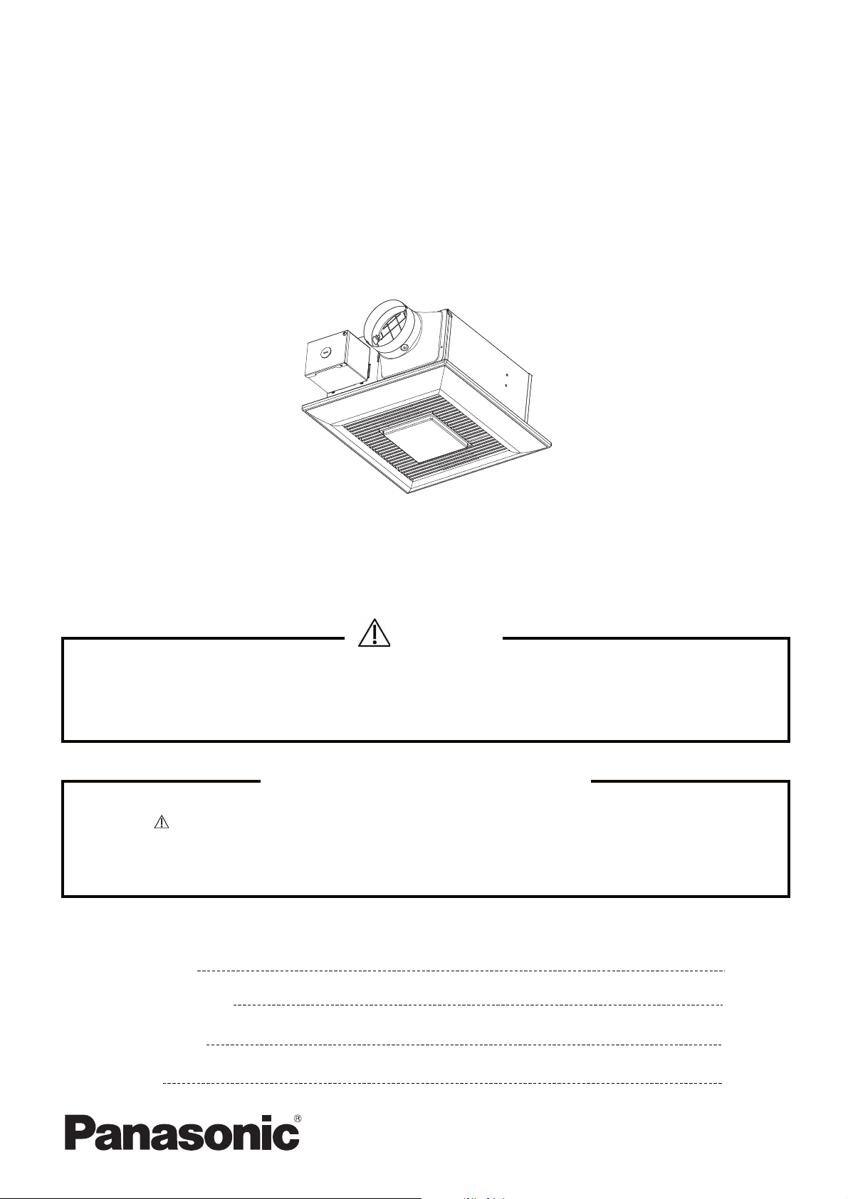
Ventilating Fan
(North America Market)
FV-08-11VFL5E
WARNING
This service information is designed for experienced repair technicians only and is not designed for use by
the general public. It does not contain warnings or cautions to advise non-technical individuals of potential
dangers in attempting to service a product. Products powered by electricity should be serviced or repaired
only by experienced professional technicians. Any attempt to service or repair the product or products dealt
with in this service information by anyone else could result in serious injury or death.
IMPORTANT SAFETY NOTICE
There are special components used in this equipment which are important for safety. These parts are
marked by in the Schematic Diagrams, Exploded Views and Replacement Parts List. It is essential
that these critical parts should be replaced with manufacturer's specified parts to prevent shock, fire
or other hazards. Do not modify the original design without permission of manufacture.
We suggest to handle such parts after the static electricity prevention.
It is forbidden to touch the PCB parts by bare hands during the repairing process.
CONTENTS
1.Specifications
2.Parts Identification
3.Wiring Diagram
PAGE
1
2~5
6
4.Parts List
7~8
Page 2

1. Specifications
1
Page 3
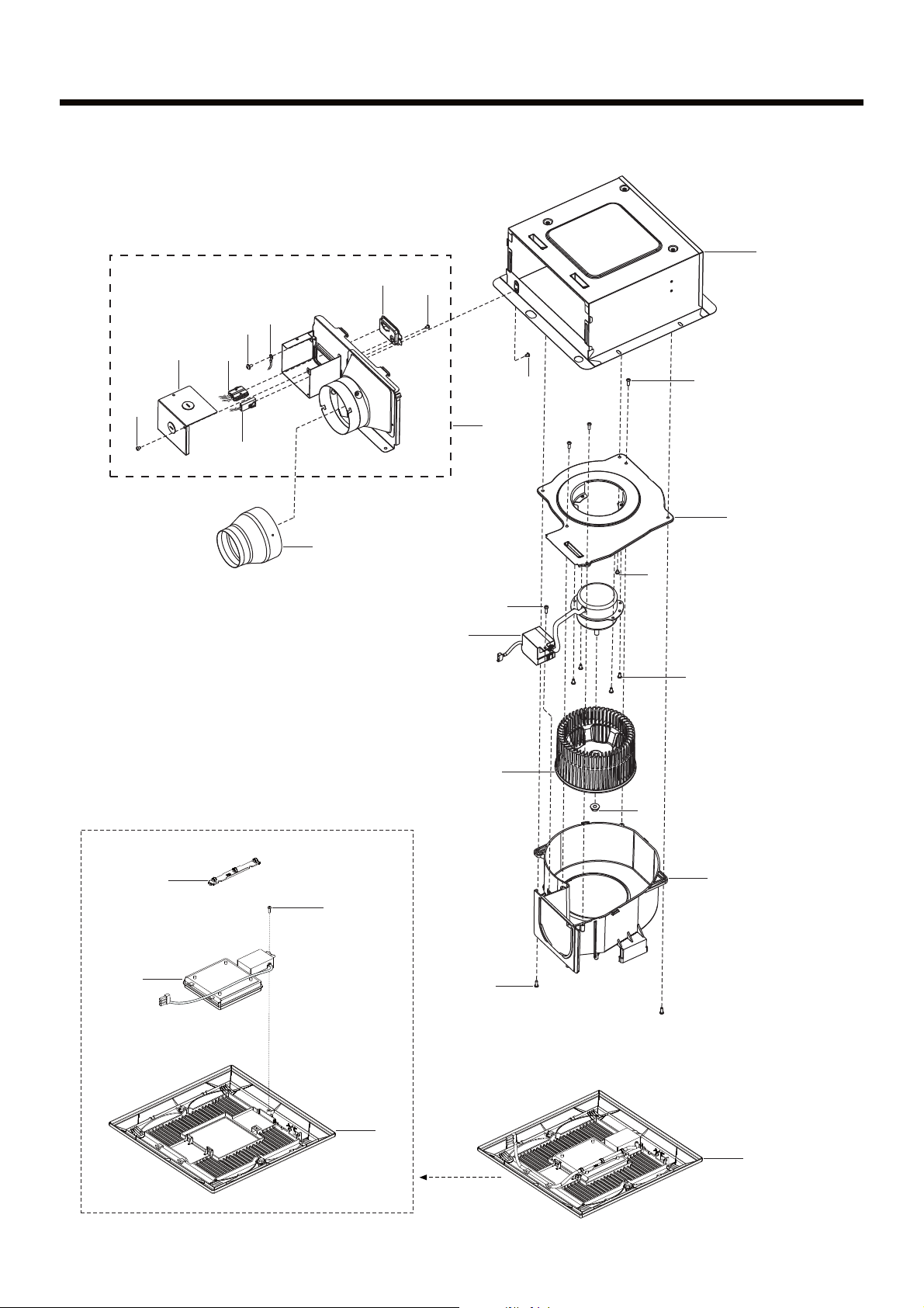
2. Parts Identification
Main Body Section
3
4
B
7
5
1
A
A
C
(3pcs)
D
(4pcs)
9
A
A
2
6
8
C
10
11
12
15
16
Louver Assembly
13
C
E
(2pcs)
17
14
2
Page 4

2. Parts Identification
Main Labels
80
08VSL3082
Not for use in cooking area-See installation
se cocine - Consulte las instrucciones de instalación.
Packing Section
CFM
110
/instructions. Non destiné à la zone de cuisson -Voir
/instructions d’installation. No usar en áreas donde
24
19
20
18
21
22
E78414
US
LISTED
FAN
23
27
28
25
29
26
30
31
32
3
Page 5

2. Parts Identification
Replace Motor Assembly Method
Step 1. Step 2. Step 3.
Haul down the louver assembly
Step 4. Step 5. Step 6.
Remove 3pcs screws
Remove the louver spring
Unplug power lead connector,
Then take out the casing unit
from the frame assembly
Unplug led unit connector ,Then
take out the louver assembly
Step 7. Step 8. Step 9.
Remove 1pc screws,Then take
out the wiring box assembly
Remove 3pcs screws,Then take
out the casing from casing unit
Remove the nut,Then take out
the blade
4
Page 6

2. Parts Identification
Replace Motor Assembly Method
Step 10. Step 11.
Remove 4pcs screws,Then take out
the motor unit from motor support
Replace Led Unit Method
Step 1. Step 2. Step 3.
()binder
Cut the binder
()Clamp
Pull out the Led unit lead from
louver assembly
Remove 1pc screw,Then take out
the led unit from louver assembly
5
Page 7

3. Wiring Diagram
6
Page 8

4. Parts List
No. Part No. Part Name Q'ty Remark
1
FFV1600146S
Frame Assembly 1
2
FFV0000152S
Adapter Assembly 1
3
FFV0900068S
Connector Plate 1
4
FFV3450010S
Earth Lead Wire 1
5
FFV0900069S
Connector Assembly (L) 1
6
FFV0900059S
Connector Assembly (V) 1
7
FFV2800020S
Junction Cover 1
8
FFV0000038S
Adapter Connector 1
9
FFV3702266S
Motor Support Unit 1
10
FFV3702267S
Motor Unit 1
11
FFV0400119S
Blade 1
12
FFV7020021S
Nut 1 For Fixing Blade
13
FFV0790115S
Casing Assembly 1 Include 1pc Packing
14 FFV3400147S Louver A ssembly 1
15 FFV2520040S Insulation Plate 1
16 FFV3400172S Led Unit 1
17 FFV3400149S Louver Unit 1
A
FFV7000108S
Truss Tap Screw 4
B
FFV7000203S
Earth Lead Wire S crew 1 For Fixing Lead Wire
C
FFV7000089S
Truss Tap Screw 5
D
FFV7000074S
Truss Tap Screw 4
E
FFV7000080S
Plus Bi nd Screw 2
No. Part No. Part Name Q'ty Remark
18
FFV4020952S
Name Plate 1
19
FFV5530075S
Switch Label 1
20
FFV0810011S
Caution Label 1 1
21
FFV0810010S
Caution Label 1
22
FFV6730045S
Warning Label 1
23
FFV2260003S
UL Mark 1
Main Body Section
Main Labels
7
Page 9

4. Parts List
No. Part No. Part Name Q'ty Remark
24
FFV2230024S
Hanger Assembly 1
25
FFV4710381S
Louver Case Assembly 1
26
FFV4650016S
Poly Cover 1 For Grille Unit Packing
27
FFV4710390S
Left Pad 1
28
FFV2540236S
Installation Instructions 1 English,For CA Market/USA Market
29
FFV0010238S
Accessory A 1
30
FFV2540237S
Installation Instructions 1 French,For USA Market
(30)
FFV2540238S
Installation Instructions 1 Spanish,For CA Market
31
FFV4710391S
Right Pad 1
32
FFV9001397S
Packing Case Assembly 1
Packing Section
8
 Loading...