

Page 1

ARCT1F409E-3
CTi Automation - Phone: 800.894.0412 - Fax: 208.368.0415 - Web: www.ctiautomation.net - Email: info@ctiautomation.net
'07・04
Page 2

Safety Precautions
CTi Automation - Phone: 800.894.0412 - Fax: 208.368.0415 - Web: www.ctiautomation.net - Email: info@ctiautomation.net
Observe the following notices to ensure personal safety or to prevent accidents.
To ensure that you use this product correctly, read this User
Make sure that you fully understand the product and information on safe.
This manual uses two safety flags to indicate different levels of danger.
WARNING
If critical situations that could lead to user’s death or serious injury is assumed by
mishandling of the product.
-Always take precautions to ensure the overall safety of your system, so that the whole
system remains safe in the event of failure of this product or other external factor.
-Do not use this product in areas with inflammable gas. It could lead to an explosion.
-Exposing this product to excessive heat or open flames could cau
battery or other electronic parts.
CAUTION
If critical situations that could lead to user’s injury or only property damage is assumed
by mishandling of the product.
-To prevent abnormal exothermic heat or smoke generation, use thi
than the maximum of the characteristics and performance that are assure in these specifications.
-Do not dismantle or remodel the product. It could lead to abnormal exothermi
smoke generation.
-Do not touch the terminal while turning on electricity. It could lead to an electric shock..
-Use the external devices to function the
-Connect the wires or connectors securely.
The loose connection might cause abnormal exothermic heat or smoke generation
-Ground the protective earth (PE) terminal (Class
an electric shock.
-Do not allow foreign matters such as liquid, flammable materials, metals to go into the
inside of the prod
-Do not undertake construction (such as connection and disconnection) while the power
supply is on.
uct. It might cause exothermic heat or smoke generation.
emerge
ncy stop and interlock circuit.
D groundi
’s Manual thoroughly before use.
se damage to the lithium
s product at the values less
c heat or
ng). Failure to do so could lead to
Copyright / Trademarks
-This manual and its contents are copylighted.
-You may not copy this manual,in whole or part,without written consent of Matsushita Electric
Works,Lt
-Windows and Windows NT are registered trademarks of Microsof
United States and/o r othe r countries.
-All other company names and product name
trademarks of their respective owners.
-Matsushita Electric Works,Ltd. pursues a policy of co
Design and performan e of its products, therefore,we re
product without notice.
d.
t Corporation in the
s are tradem
arks or registered
ntinuous imp
serve the right to change the manual/ c
rovement of the
Page 3

CTi Automation - Phone: 800.894.0412 - Fax: 208.368.0415 - Web: www.ctiautomation.net - Email: info@ctiautomation.net
Table of Contents
Before You Start
Differences in Functions Between Versions of Controller
Programming Tool Restrictions
1. Features, Functions and Restrictions................................................. 1-1
1.1 Features and Functions of the Unit...............................................................................1-2
1.2 Unit Types ........................................................................................................................1-6
1.2.1 FP-X Control Units......................................................................................................1-6
1.2.2 FP-X Expansion Unit...................................................................................................1-7
1.2.3 FP-X Expansion FP0 Adapter.....................................................................................1-7
1.2.4 Add-on Cassettes
1.2.5 Related Parts ..............................................................................................................1-9
(Communication cassettes/Application cassettes)........................1-8
1.3 Restrictions on Unit Combinations .............................................................................1-10
1.3.1 Restrictions on FP-X Expansion Unit
1.4 Programming Tools.......................................................................................................1-14
1.4.1 Tools Needed for Programm
1.4.2 Software Environment and Suitable Cable...............................................................1-1
ing................................................................................1-14
........................................................................1-10
4
2. Specifications and Functions of Control Unit....................................2-1
2.1 Parts and Functions........................................................................................................2-2
2.1.1 Parts and Functions....................................................................................................2-2
2.2 Powe
2.2.1 AC Power Supply........................................................................................................2-5
2.2.2 Service Power Supply for Input (Output) (A
2.2.3 DC Power Supply........................................................................................................2-5
2.3 Input Specifications ........................................................................................................2-6
2.3.1 Relay (Ry) Type..........................................................................................................2-6
2.3.2 Transi
2.4 Output Specifications .....................................................................................................2-8
2.4.1 Relay (Ry) Type..........................................................................................................2-8
2.4.2 Transis
2.4.3 Transis
r Supply Specifications .........................................................................................2-5
C Power Supply Type Only)...................2-5
s
tor (Tr) Type (Common to NPN and PNP)......................................................2-7
tor (Tr) Type (NPN).........................................................................................2-9
tor (Tr) Type (PNP) .......................................................................................2-10
2.5 Terminal Layout
2.5.1 Relay Type................................................................................................................2-14
2.5.2 Transistor type
.............................................................................................................2-14
..........................................................................................................2-16
Page 4

CTi Automation - Phone: 800.894.0412 - Fax: 208.368.0415 - Web: www.ctiautomation.net - Email: info@ctiautomation.net
3. Expansion Cassette and Expansion FP0 Adapter Specifications ....3-1
3.1 Expansion Method...........................................................................................................3-2
3.1.1 Expansion Using the Expansion Cable.......................................................................3-2
3.2 FP-X Expansion Unit .......................................................................................................3-4
3.2.1 Parts and Functions
3.2.2 Power Supply Specifications.......................................................................................3-5
3.2.3 Input and output specifications ...................................................................................3-6
3.2.4 Terminal layout............................................................................................................3-9
....................................................................................................3-4
3.3 FP-X Expansion FP0 Adapter
3.3.1 Overview ...................................................................................................................3-12
3.3.2 Parts and Functions
..................................................................................................3-13
.......................................................................................3-1
2
4. I/O Allocation.........................................................................................4-1
4.1 I/O Allocation....................................................................................................................4-2
4.2 Allocation of FP-X Control Unit......................................................................................4-3
4.3 FP0 Expansion Unit Allocation
4.4 Allocation of FP0 Expansion Unit..................................................................................4-4
4.4.1 I/O A
4.4.2 Number of Expansion Units and I/O Allocation...........................................................4-4
4.4.3 I/O Allocation of FP0 Expansion Unit..........................................................................4-5
4.5 I/O Allocation of FP-X Add-on Cassette........................................................................4-6
llocation
...............................................................................................................4-4
......................................................................................4-3
5. Installation and Wiring..........................................................................5-1
5.1 Installation........................................................................................................................5-2
5.1.1 Installation Environment and Space ...........................................................................5-2
5.2 Installation Using Expansion Cable...............................................................................5-5
5.3 Expansion Method of FP0 Expansion Unit ...................................................................5-8
5.4 How
5.5 Powe
to Install Add-on Cassette......................................................................................5-9
r Supply.................................................................................................................5-11
ii
Page 5

5.6 Wiring of Input and Output...........................................................................................5-15
CTi Automation - Phone: 800.894.0412 - Fax: 208.368.0415 - Web: www.ctiautomation.net - Email: info@ctiautomation.net
5.7 Wiring of Terminal Block ..............................................................................................5-18
5.8 Wiring of Add-on Cassette Terminal Block ................................................................5-20
5.9 Installation and Setting of Backup Battery
5.9.1 Installat
5.9.2 System R
5.9.3 Time for Replacement of Back
5.9.4 Lifetime of Backu
5.10 Safety Measu
5.10.1 Safety Measures.....................................................................................................5-27
5.10.2 Momentary Power Failures.....................................................................................5-27
5.10.3 Protection of Output Sections.................................................................................5-2
ion of Backup Battery ...................................................................................5-24
egister Setting ...........................................................................................5-25
up Battery.................................................................5-25
p Battery........................................................................................5-26
res ..........................................................................................................5-27
.................................................................5-23
7
6. Tool Port and USB Port........................................................................ 6-1
6.1 Tool Port and USB Port...................................................................................................6-2
6.2 Functions of Tool Port ....................................................................................................6-3
6.2.1 Tool Port......................................................................................................................6-3
6.2.2 Tool Port Setting .........................................................................................................6-4
6.3 USB Port...........................................................................................................................6-6
6.3.1 Functions of USB Port
6.3.2 USB Port Setting.........................................................................................................6-7
6.3.3 USB Connection
6.3.4 USB Connection Procedure........................................................................................6-9
6.3.5 Installat
6.3.6 Installat
6.3.7 Confirming COM Ports..............................................................................................6-1
6.3.8 Communication with FPWIN GR
6.3.9 Reinstallation of USB Driver
6.3.10 Restric
ion of FPWIN GR............................................................................................6-9
ion of USB Driver..........................................................................................6-10
tions on USB Communication......................................................................6-22
................................................................................................6-6
.........................................................................................................6-8
8
...............................................................................6-20
.....................................................................................6-21
7. Communication Cassette..................................................................... 7-1
7.1 Functions and Types.......................................................................................................7-2
7.1.1 Overview of Communication Cassette........................................................................7-2
7.1.2 Functions of Communic
7.1.3 Communication Cassettes..........................................................................................7-7
7.1.4 Examples of Connection
7.1.5 Names and Principl
7.1.6 About USB Port (For C30/C60 Only
7.2 Communication Specifications....................................................................................7-15
ation Cassette.......................................................................7-3
...........................................................................................7-12
e Applications of the Ports.........................................................7-13
)........................................................................7-14
iii
Page 6

7.2.1 Precaution When Using RS485 Port.........................................................................7-18
CTi Automation - Phone: 800.894.0412 - Fax: 208.368.0415 - Web: www.ctiautomation.net - Email: info@ctiautomation.net
7.3 Communication Function 1: Computer Link...............................................................7-19
7.3.1 Computer Link...........................................................................................................7-19
7.3.2 1:1 Communicati
7.3.3 1:N Communication (Computer Link)
7.3.4 MEWTOCOL Master (Sample Program)
7.4 Communication Function 2: General-purpose Serial Communication....................7-3
7.4.1 General-purpose Serial Communication...................................................................7-3
7.4.2 Communication with External Devic
7.4.3 Connection with 1:1 Communication (General-purpos
7.4.4 1:N Communication
7.5 Communication Function 3: PC(PLC) Link.................................................................7-59
7.5.1 PC(PLC) Link............................................................................................................7-59
7.5.2 Setting Communication Parameters
7.5.3 Monitoring .................................................................................................................7-70
7.5.4 Connection Example of PC(PLC) Link......................................................................7-71
7.5.5 PC(PLC) Link Response
7.6 Communication Function 4: MODBUS RTU Communication...................................7-78
7.6.1 MODBUS RTU Communica
7.6.2 MEWTOCOL Master (Sample Program)
on (Computer link) .........................................................................7-27
........................................................................7-30
..................................................................7-33
5
5
es......................................................................7-37
e serial communication).......7-47
(General-purpose Serial Communication)................................7-58
.........................................................................7-61
Time..................................................................................7-74
tion................................................................................7-78
..................................................................7-82
8. Application Cassette.............................................................................8-1
8.1 Expansion of Application Cassette ...............................................................................8-2
8.2 Application Cassettes.....................................................................................................8-3
8.3 Specifications ..................................................................................................................8-5
8.3.1 FP-X Analog Input Cassette........................................................................................8-5
8.3.2 FP-X Input Cassette....................................................................................................8-8
8.3.3 FP-X Output Cass
8.3.4 FP-X Pulse I/O Cassette...........................................................................................8-23
8.3.5 FP-X Master Memory Cass
ette
...............................................................................................8-21
ette.................................................................................8-26
9. High-speed Counter, Pulse Output and PWM Output Functions (For
Tr Type) .................................................................................................9-1
9.1 Overview of Each Functions...........................................................................................9-2
9.1.1 Usable Units and Cassettes........................................................................................9-2
9.1.2 Three Pulse I/O Functions ..........................................................................................9-2
tion
9.1.3 Performance of Pulse I/O Func
9.2.1 Specifications..............................................................................................................9-4
9.2.2 Functions Used and Restrictions................................................................................9-6
9.2.3 Booting Time.............................................................................................................9-10
.............................................................................9-3
iv
Page 7

9.3 High-speed Counter Function......................................................................................9-11
CTi Automation - Phone: 800.894.0412 - Fax: 208.368.0415 - Web: www.ctiautomation.net - Email: info@ctiautomation.net
9.3.1 Overview of High-speed Counter Function
9.3.2 Input Modes and Count.............................................................................................9-11
9.3.3 Minimum Input Pulse Width......................................................................................9-12
9.3.4 I/O Allocation
9.3.5 Instruc
9.3.6 Sample program (Control Unit and Main Unit I/O)....................................................9-16
.............................................................................................................9-13
tions used with High-speed Counter Function...............................................9-13
...............................................................9-11
9.4 Pulse Output Function..................................................................................................9-19
9.4.1 Overview of Pulse Output Function
9.4.2 Types of Pulse Output Method and Operation Modes .............................................9-2
9.4.3 I/O Allocation
9.4.4 Pulse output cont
9.4.5 Wiring for Pulse Output Sample Program (F171 to F174)
9.4.6 Positioning Control Instruc
9.4.7 Positioning Control In
9.4.8 Pulse Output Inst
9.4.9 Positioning Control Inst
9.4.10 Pulse Output Instruc
9.5 PWM Output Function (Pulse I/O Cassette)................................................................9-51
9.5.1 Overview of PWM Output Function...........................................................................9-51
9.5.2 Instruc
.............................................................................................................9-23
rol instructions (F0) (F1)................................................................9-25
tion F171 - Trapezoidal...................................................9-28
struction F171 – Home Return (Common to Transistor type) 9-33
ruction F172 – JOG operation.......................................................9-38
ruction F174 – Data Table Control ......................................9-42
tion F175 – Linear Interpolation.............................................9-44
tion to be Used for PWM Output Function.....................................................9-51
..........................................................................9-19
0
........................................9-27
10. High-speed counter, Pulse Output and PWM Output functions (For Ry
Type)....................................................................................................10-1
10.1 Overview of Each Functions ......................................................................................10-2
10.1.1 Usable Units and Cassettes....................................................................................10-2
10.1.2 Three Pulse I/O Func
10.1.3 Performance of Pulse I/O Func
10.2.1 Specifications
10.2.2 Functions
10.2.3 Booting Time...........................................................................................................10-8
..........................................................................................................10-4
Used and Restrictions............................................................................10-7
tions......................................................................................10-2
tion.........................................................................10-3
10.3 High-speed Counter Function....................................................................................10-9
10.3.1 Overview of High-speed Counter Function.............................................................10-9
10.3.2 Input Modes and Count...........................................................................................10-9
10.3.3 Minimu
10.3.4 I/O Allocation
10.3.5 Instructions used with High-speed Counter Function
10.3.6 Sample program (Control Unit and Main Unit I/O)................................................10-14
10.3.7 Sample program (Pulse
10.4 Pulse Output Function (Pulse I/O Cassette)...........................................................10-20
10.4.1 Overview of Pulse Output Function ......................................................................10-20
10.4.2 Types of Pulse Output Method and Operation Modes .........................................10-21
10.4.3 I/O Allocation
10.4.4 Pulse output control ins
10.4.5 Wiring for Pulse Output Sample P
m Input Pulse Width
.........................................................................................................10-11
.........................................................................................................10-24
..................................................................................10-10
...........................................10-11
I/O Cassette)..................................................................10-17
tructions (F0) (F1)............................................................10-25
rogram (F171 to F174)....................................10-27
v
Page 8

10.4.6 Positioning Control Instruction F171 - Trapezoidal...............................................10-28
CTi Automation - Phone: 800.894.0412 - Fax: 208.368.0415 - Web: www.ctiautomation.net - Email: info@ctiautomation.net
10.4.7 Positioning Control Instructio
33
10.4.8 Pulse Output Instruc
10.4.9 Positioning Control Inst
10.4.10 Pulse Output Inst
10.5 PWM Output Function (Pulse I/O Cassette)............................................................10-51
10.5.1 Overview of PWM Output Function
10.5.2 Instruction to be Used
tion F172 – JOG operation...................................................
ruction F175 – Linear Interpolation .........................................10-44
n F171 – Home Return (Common to Transistor type) 10-
10-38
ruction F174 – Data Table Control...................................10-42
.......................................................................10-51
for PWM Output Function.................................................10-51
11. Security Functions.............................................................................. 11-1
11.1 Type of Security Functions.........................................................................................11-2
11.2 Password Protect Function........................................................................................11-2
11.2.1 Password Setting....................................................................................................11-3
11.3 Upload Protection........................................................................................................11-7
11.3.1 Upload Protection Setting .......................................................................................11-7
11.4 Table of Security Set
tings/Cancel..............................................................................11-9
12. Other Functions ..................................................................................12-1
12.1 Transfer Function between Memories.......................................................................12-2
12.2 Function of Master Memory Cassette........................................................................12-3
12.2.1 Realtime Clock Function
12.2.2 Master Memory Func
12.2.3 Relation between S
12.2.4 Handling of Master Memories Created with
12.3 P13 (ICWT) Instruction
12.4 Analog Potentiometer .................................................................................................12-9
12.4.1 Overview of Analog Potentiometer .........................................................................12-9
12.4.2 Example Showing How to Use Analog Potentiometer
12.5 Sampling Trace Function..........................................................................................12-10
12.5.1 Overview...............................................................................................................12-10
12.5.2 Details of Sampling Trace Function
12.5.3 How to Use Sampling Trace.................................................................................12-11
.........................................................................................12-3
tion ........................................................................................12-5
ecurity Setting and Transmission ............................................12-6
Different Models ................................12-7
................................................................................................12-8
............................................12-9
......................................................................12-10
12.6 Time Constant Processing .......................................................................................12-13
vi
Page 9

13. Self-Diagnostic and Troubleshooting............................................... 13-1
CTi Automation - Phone: 800.894.0412 - Fax: 208.368.0415 - Web: www.ctiautomation.net - Email: info@ctiautomation.net
13.1 Self-Diagnostic function.............................................................................................13-2
13.1.1 LED Display for Status Condition............................................................................13-2
13.1.2 Operation Mode When an Error Oc
13.2 Troubleshooting ..........................................................................................................13-4
13.2.1 If ERROR LED is Flashing
13.2.2 If ERROR LED is ON
13.2.3 ALL LEDs are OFF .................................................................................................13-6
13.2.4 Diagnosing Output Malfunc
13.2.5 A Protect Error Message Appears
13.2.6 PROG Mode does not Change to RUN..................................................................13-8
13.2.7 A Communica
13.2.8 A Communication Error has
13.2.9 A Communication Error has
13.2.10 Expansion Unit does not Operate
tion Error has
......................................................................................13-4
..............................................................................................13-5
tion
Occurred through RS485 ..........................................13-9
Occurred through RS232C........................................13-9
Occurred through RS422 ........................................13-10
curs.................................................................13-3
...............................................................................13-7
..........................................................................13-8
.......................................................................13-10
14. Precautions During Programming..................................................... 14-1
14.1 Use of Duplicated Output ...........................................................................................14-2
14.1.1 Duplicated Output...................................................................................................14-2
14.1.2 When Output is Repeated with an OT, KP,
SET or RST Instruction......................14-2
14.2 Handling BCD Data......................................................................................................14-4
14.2.1 BCD Data................................................................................................................14-4
14.2.2 Handling BCD Data in the PLC...............................................................................14-4
14.3 Handling Index Registers
14.3.1 Index Registers.......................................................................................................14-5
14.3.2 Memory Areas Which can be Modified with Index Regis
14.3.3 Example of Using an Index Register
14.4 Operation Errors..........................................................................................................14-7
14.4.1 Outline of Operation Errors.....................................................................................14-7
14.4.2 Operation Mode When an Operation Error Oc
14.4.3 Dealing with Operation Errors.................................................................................14-7
14.4.4 Points to Chec
14.5 Instruction of Leading Edge Detection Method........................................................14-9
14.5.1 Instructions of Leading Edge Detection Method
14.5.2 Operation and Precautions When RUN Starts .....................................................14-10
14.5.3 Precautions
14.6 Precautions for Programming..................................................................................14-13
14.7 Rewr
14.7.1 Operation of Rewrite During RUN.........................................................................14-14
14.7.2 Cases Where Rewriting
ite Function During RUN..................................................................................14-14
k in Program....................................................................................14-8
When Using a Control Instruction.....................................................14-11
...........................................................................................14-5
ters .................................14-5
......................................................................14-6
curs ................................................14-7
.....................................................14-9
During Run is not Possible.............................................14-15
vii
Page 10

14.7.3 Procedures and Operation of Rewrite During RUN..............................................14-17
CTi Automation - Phone: 800.894.0412 - Fax: 208.368.0415 - Web: www.ctiautomation.net - Email: info@ctiautomation.net
14.8 Processing During Forced Input and Output..........................................................14-19
14.8.1 Processing when forced input/output is initiated during RUN...............................14-19
15. Specifications......................................................................................15-1
15.1 Table of Specifications................................................................................................15-2
15.1.1 General Specifications............................................................................................15-2
15.1.2 Performance Specific
15.1.3 Communication Specifications
15.2 Table of I/O Number Allocation................................................................................15-13
15.2.1 I/O Allocation of FP-X Control Unit
15.2.2 FP0 Expansion Unit Allocation..............................................................................15-13
15.2.3 FP0 Expansion Unit Allocation..............................................................................15-13
15.2.4 I/O Allocation of FP-X Add-on Cas
ations ....................................................................................15-7
..............................................................................15-10
.......................................................................15-13
sette................................................................15-15
15.3 Relays, Memor
y Areas and Constants....................................................................15-16
16. Dimensions..........................................................................................16-1
16.1 Dimensions...................................................................................................................16-2
16.1.1 Control Unit.............................................................................................................16-2
16.1.2 Expansion Unit
16.1.3 Expansion FP0 Adapter..........................................................................................16-3
16.1.4 Dimension Diagram for Ins
........................................................................................................16-2
tallation.........................................................................16-3
17 Appendix....................................................................................………17-1
17.1 System Registers / Special Internal Relays / Special Data Registers.…………….17-3
17.1.1 Table of System Registers for FP-X........................................………………………..............17-5
17.1.2 Table of Special Internal Relays for FP-X.....................................………………………......17-17
17.1.3 Table of Special Data Registers for FP-X..........................……………………….................17-28
17.2 Table of Basic Instructions................................................................……………….17-50
17.3 Table of High-level Instructions.........................................................………………17-84
17.4 Table of Error codes........................................................................……………….17-144
17.5 MEWTOCOL-COM Communication Commands......................………………......17-158
17.6 Hexadecimal/Binary/BCD....................................................……………….............17-159
17.7 ASCII Codes....................................................................………………...................17-160
viii
Page 11

Before You Start
CTi Automation - Phone: 800.894.0412 - Fax: 208.368.0415 - Web: www.ctiautomation.net - Email: info@ctiautomation.net
Installation environment
Do not use the unit where it will be exposed to the following:
• Direct sunlight and ambient temperatures outside the range of 0°C to 55°C /32°F to 131°F.
• Ambient humidity outside the range of 10 to 95% RH (at 25°C, non-condensing) and sudden
temperature changes causing condensation.
• Inflammable or corrosive gas.
• Excessive vibration or shock.
• Excessive airborne dust, metal particles or salts.
• Water, oil or chemicals in any from including spray or mist.
• Benzine, paint thinner, alcohol or other organic solvents or strong alkaline solutions such as ammonia
or caustic soda.
• Influence from power transmission lines, high voltage equipment, power cables, power equipment,
radio transmitters, or any other equipment that would generate high switching surges.
Static electricity
• Before touching the unit, always touch a grounded piece of metal in order to discharge static electricity.
• In dry locations, excessive static electricity can cause problems.
Cleaning
• Do not use thinner based cleaners because they deform the unit case and fade colors.
Power supplies
• It is recommended to use an insulated power supply with an internal protective circuit for resistance to
noise.
• If using a power supply without a protective circuit, power should be supplied through a protective
element such as a fuse.
Power supply sequence
• Have the power supply sequence such that the power supply of the control unit turns off before the
power supply for input and output.
• If the power supply for input and output is turned off before the power supply of the control unit, the
control unit will detect the input fluctuations and may begin an unscheduled operation.
Before turning on the power
When turning on the power for the first time, be sure to take the precautions given below.
• When performing installation, check to make sure that there are no scraps of wiring, particularly
conductive fragments, adhering to the unit.
• Verify that the power supply wiring, I/O wiring, and power supply voltage are all correct.
• Sufficiently tighten the installation screws and terminal screws.
• Set the mode selector to PROG. Mode.
ix
Page 12

Before entering a program
CTi Automation - Phone: 800.894.0412 - Fax: 208.368.0415 - Web: www.ctiautomation.net - Email: info@ctiautomation.net
Be sure to perform a program clear operation before entering a program.
Operation procedure when using FPWIN GR Ver.2
Select “Online Edit Mode” on the FPWIN GR “On line” menu.
Select “Clear Program” on the “Edit” menu.
When the confirmation dialog box is displaye d, click on “Yes” to clear the program.
Request concerning program storage
To prevent the accidental loss of programs, the user should consider the following measures.
• Drafting of documents
To avoid accidentally losing programs, destroying files, or overwriting the contents of a file, documents
should be printed out and then saved.
• Specifying the password carefully
The password setting is designed to avoid programs being accidentally overwritten. If the password is
forgotten, however, it will be impossible to overwrite the program even if you want to. Also, if a
possword is forcibly bypassed, the program is deleted. When specifying the password, note it in the
specifications manual or in another safe location in case it is forgotten at some point.
• Upload protection
When the upload protection setting is specified, programs will be disalbed to be read out. If the setting
is cancelled forcibly, all programs and system registers will be deleted. Therefore, note that programs
and system registers should be managed on your own responsibility.
Backup battery
Do not install the battery when it is not used.
There is a possibility of leak if the battery remains discharged.
x
Page 13

Differences in Functions Between Versions of Controller
CTi Automation - Phone: 800.894.0412 - Fax: 208.368.0415 - Web: www.ctiautomation.net - Email: info@ctiautomation.net
Version Usable model Usable functions
UP/DOWN switching of high-speed counter by SYS instruction
Real number basic compare instructions 18 types
STF=S1, S2 ANF=S1, S2 ORF=S1, S2
STF<>S1, S2 ANF<>S1, S2 ORF<>S1, S2
V1.10 Ry type -
V1.20 Ry type -
V2.00 Ry type Tr type
Note) The Ry and Tr types with the same specifications have the same version name
STF>S1, S2 ANF>S1, S2 ORF>S1, S2
STF>=S1, S2 ANF>=S1, S2 ORF>=S1, S2
STF<S1, S2 ANF<S1, S2 ORF<S1, S2
STF<=S1, S2 ANF<=S1, S2 ORF<=S1, S2
System register 36 for setting expansion unit recognition time
MEWTOCOL master function
F145(SEND) Data send
F146(RECV) Data receive
E356(EZPID) Easy PID instruction
Time constant processing of input (Refer to Chapter 12.6.)
CPU input: System register setting
Other input: F182(FILTR) Time constant processing
Sampling trace function (Refer to Chapter 12.5.)
Sampling by instrucitons
F155(SMPL) Sampling
F156(STRG) Sampling trigger
Sampling by specifying time
Leading contact, trailing contact instructions
ST↑ AN↑ OR↑
ST↓ AN↓ OR↓
An arbitrary device can be specified for the setting value of
Timer/counter instruction.
e.g.) TML 0, DT0
Other additional convenient instructions
F252(ACHK) ASCII data check
F284(RAMP) Inclination output
Baud rate setting (300, 600, 1200 bps) by SYS instruction
High-speed operaiton
F0(MV) and F1(DMV) instructions Execution time: Approx. 1us
Only when every operands are without index modifier.
Function addition to exsiting instructions
F70(BCC) Block check code calculation
F356(EZPID) Easy PID instruction
Reference: <Programming Manual ARCT1F313E>
xi
Page 14

Programming Tool Restrictions
CTi Automation - Phone: 800.894.0412 - Fax: 208.368.0415 - Web: www.ctiautomation.net - Email: info@ctiautomation.net
Restrictions on usable programming tools depending on the units (as of August, 2006)
Type of unit
Type of programming tool
Windows software
Windows software
Conforms to
IEC61131-3
MS-DOS software
Handy programming
unit
FP memory loader
AFPX-C14R
AFPX-C30R
AFPX-C60R
FPWIN GR Ver.2
FPWIN GR Ver.1 Not used Not used
FPWIN Pro
Ver.5
NPST-GR Ver.4 Not used Not used
NPST-GR Ver.3 Not used Not used
AFP1113V2
AFP1114V2
AFP1113
AFP1114
AFP1111A
AFP1112A
AFP1111
AFP1112
AFP8670
AFP8671
Used
(Ver. 2.5 or later)
Used
(Ver. 5.1 or later)
Not used Not used
Not used Not used
Not used Not used
(Only porgrams and system registers can be transmitted.)
AFPX-C14T, C14TD, C14P, C14PD
AFPX-C30T, C30TD, C30P, C30PD
AFPX-C60T, C60TD, C60P, C60PD
Used
(Ver. 2.70 or later)
Used
(Ver. 5.22 or later)
Used
Note: Precautions concerning version upgrade
• In case of using FPWIN GR Ver.1, please purchase upgrade model FPWIN GR Ver.2.
• FPWIN GR Ver. 2.0 can be upgraded to Ver. 2.5 or later free of charge at our web site
(
http://www.nais-e.com/plc/).
• In case of using FPW
• FPWIN Pro Ver. 5.0 can be free of charge at our web site (
• The handy
Do not download any programs for other units such as FP1 to the FP-X using the handy programming
unit .
programmign unit cannot be used.
IN Pro Ver.4, please purchase upgrade model FPWIN Pro Ver.5.
http://www.nais-e.com/plc/).
xii
Page 15

CTi Automation - Phone: 800.894.0412 - Fax: 208.368.0415 - Web: www.ctiautomation.net - Email: info@ctiautomation.net
Chapter 1
Features, Functions and Restrictions
Page 16

1.1 Features and Functions of the Unit
CTi Automation - Phone: 800.894.0412 - Fax: 208.368.0415 - Web: www.ctiautomation.net - Email: info@ctiautomation.net
Features
• Compact size general-purpose PLC that is suitable for the small-scale facility control.
• Can be directly connected to a personal computer using USB communication port.
• High demensional security functions to deal with copying programs.
• Supports analog control.
• Following items are provided as options,
- Application cassettes, such as the positioning control function by the high-speed counter and
pulse output.
- Fulfilling communication cassettes.
- Realtime clock function.
Basic functions as compact size general-purpose PLC suitable for the small-scale facility control
Basic functions including the followings are equipped even though it is a general-pur pose sytle such as
AC power supply, screw terminal block and relay output.
1. 32k-step program capacity
2. 0.32 μs command processing speed
3. Max. 382-points I/O control
Single-phase 8-channel and 2-phase 4 channel high-speed counter functions are equipped for
the control unit.
Fulfilling function enhancement
Various add-on cassettes are available as options (such as 10 types of application cassettes and
6 types of communication cassette).
• Application cassettes
DC 8-point input type, transistor 8-point NPN output type, transistor 6-point PNP output type, DC 4-point
input + transistor 3-point NPN output type, analog 2-ch output type, analog 2-ch input + analog 1-ch
output type, thermocouple 2-ch type, analog 2-ch input type, high-speed counter input + pulse output
type, master memory type with realtime clock (32k-step program can be copied and stored.)
• Communication cassettes
1-ch RS232C type, 2-ch RS232C type, 1-ch RS485/RS422 changeover type, 1-ch RS232C + 1-ch
RS485 type, Ethernet + 1-ch RS232C type, 2-ch RS485 type
FP0 expansion units can be connected as well as the exclusive expansio n unit.
A maximum of 3 FP0 expansion units can be connected using the expansion FP0 adapter.
A personal computer can be directly connected with the USB communication port.
A personal computer can be directly connected with the USB cable (excluding C14).
The USB⇔RS232C conversion adapter/cable is not necessary.
(A tool port (RS232C) is also equipped.)
1-2
Page 17

High demensional security functions to deal with copying programs.
CTi Automation - Phone: 800.894.0412 - Fax: 208.368.0415 - Web: www.ctiautomation.net - Email: info@ctiautomation.net
The uploading disabling function prohibits uploading (readin g) programs in the PLC main unit and
prevent illegal copying.
(It also enables to transfer the programs to the FP-X master memory cassette, when the uploading
disabling function is specified).
The protection for programs can be selected from
3 security methods.
• 4-digit password
• 8-digit password
• Uploading disabling
A full range of communication functions
Using the Tool port (RS232C) provided as a standard feature on the main unit, communication can be
carried out with a display panel or computer. Additionally, communication cassettes with RS232C,
RS485 and Ethernet interfaces are available as an option. Installing a 2-channel RS232C type
communication cassette in the FP-X makes it possible to connect two devices with RS232C port. A full
lineup of communication functions means you can also work with 1:N communication (up to 99 units)
and PC(PLC) link function (up to 16 units).
Controlling two devices with RS232C port with one FP-X
When using the 2-channel RS232C type communication cassette
1:N communication possible with up to 99 stations (units)
When using the 1-channel RS485/RS422 type communication cassette
When using the 1-channel RS485 and 1-channel RS232C in combination
Link with FP2 and FPΣ is possible
Data sharing between small size and medium size PLCs is easily achievable in one network.
The FP-X supports MEWNET-W0, and the programless PLC link with the FP2 or FP Σ is possible.
1-3
Page 18

Supports Modbus RTU
CTi Automation - Phone: 800.894.0412 - Fax: 208.368.0415 - Web: www.ctiautomation.net - Email: info@ctiautomation.net
It can be used as a master unit/slave units (F145 and F146 instructions).
It can be easily communicated with a temperature control device, inverter, FP-e or overseas PLCs.
It is possible to communicate with up to 99 units
MEWTOCOL communication
It can be used as a master unit/slave units (F145 and F146 instructions).
It can be easily communicated with a PLC, image processor, temperature control device, message
runner or eco-power meter.
It is possible to communicate with up to 99 units
1-4
Page 19
Positioning control supported through high-speed counter and pulse output
CTi Automation - Phone: 800.894.0412 - Fax: 208.368.0415 - Web: www.ctiautomation.net - Email: info@ctiautomation.net
With the FP-X Tr type, a high-speed counter function can be used by using the CPU I/O.
With the FP-X Ry type, a high-speed counter and pulse output functions can be used by using the pulse
I/O cassette. The pulse output function supports frequencies of up to 100kHz, enabling positioning
control using a stepping motor or servo motor.
Note) The pulse I/O cassette cannot be used for the FP-X Tr type.
Measurement using high-speed counter supported
Increment input mode, decrement input mode, 2-phase input mode, individual input mode, and direction
discrimination mode are supported.
Note) Differs depending on combinations.
Positioning control based on pulse output supported
Pulse/direction and clockwise/counter –clockwise output are supporte d.
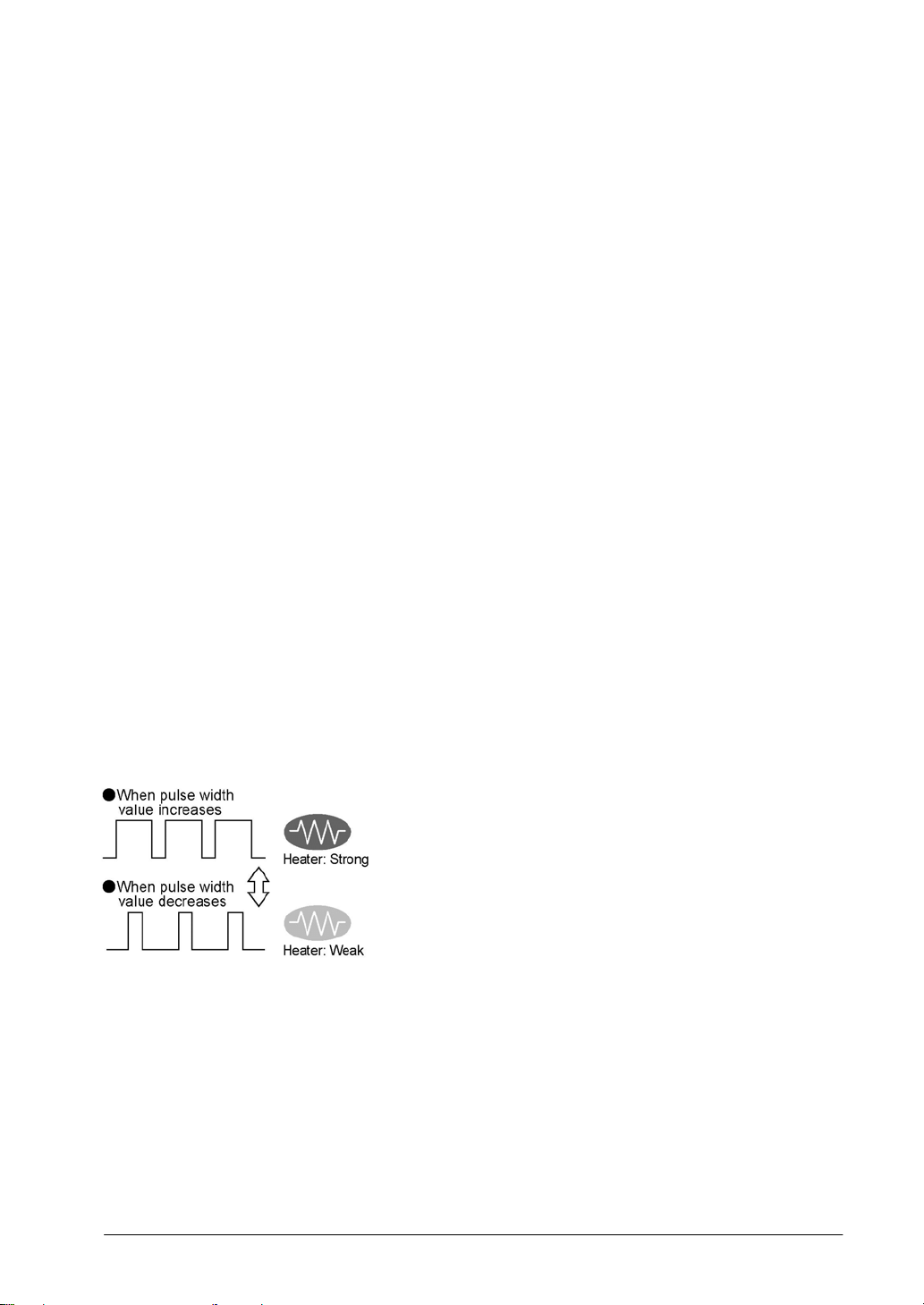
Heater control based on PWM output function supported
The pulse output at any duty ratio can be picked up with special instruction.
Analog potentionmeter (volume dial)
An analog potentionmeter (volume dial) is provided as a standard feature. This can be used in
applications such as analog timers, without using the programming tools.
Realtime clock function can be added
Optional FP-X master memory cassette (AFPX-MRTC) and backup battery enables the realtime clock
function.
1-5
Page 20
1.2 Unit Types
CTi Automation - Phone: 800.894.0412 - Fax: 208.368.0415 - Web: www.ctiautomation.net - Email: info@ctiautomation.net
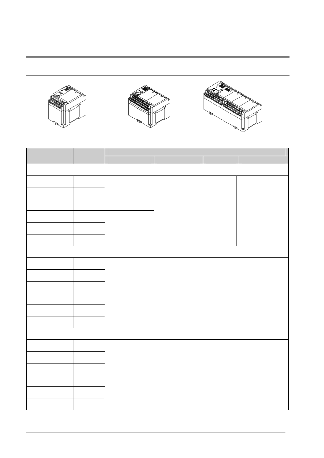
1.2.1 FP-X Control Units
C14 C30 C60
Product No.
Relay type (Ry type)
AFPX-C14R 8/6
AFPX-C30R 16/14
AFPX-C60R 32/28
AFPX-C14RD 8/6
AFPX-C30RD 16/14
AFPX-C60RD 32/28
Transistor type (NPN) (Tr type)
AFPX-C14T 8/6
AFPX-C30T 16/14
AFPX-C60T 32/28
AFPX-C14TD 8/6
AFPX-C30TD 16/14
No. of I/O
points
Specifications
Power supply Input Output Connection
100 to 240 V AC
24 V DC
(Common
polarities
+ & - common)
24 V DC
100 to 240 V AC
24 V DC
(Common
polarities
+ & - common)
24V DC
Relay Terminal block
Transistor
(NPN)
Terminal block
AFPX-C60TD 32/28
Transistor type (PNP) (Tr type)
AFPX-C14P 8/6
AFPX-C30P 16/14
AFPX-C60P 32/28
AFPX-C14PD 8/6
AFPX-C30PD 16/14
AFPX-C60PD 32/28
100 to 240 V AC
24V DC
24 V DC
(Common
polarities
+ & - common)
Transistor
(PNP)
Terminal block
1-6
Page 21
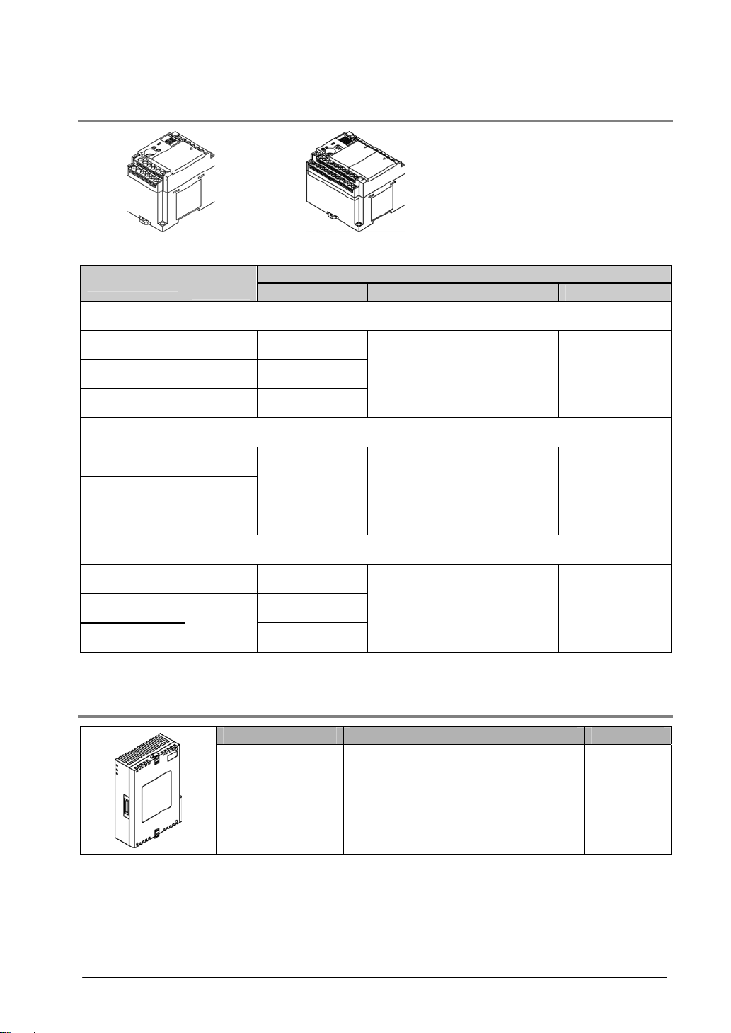
1.2.2 FP-X Expansion Unit
CTi Automation - Phone: 800.894.0412 - Fax: 208.368.0415 - Web: www.ctiautomation.net - Email: info@ctiautomation.net
E16 E30
Product No.
Relay type (Ry type)
AFPX-E16R 8/8 AFPX-E30R 16/14 100 to 240 V AC
AFPX-E30RD 16/14 24 V DC
Transistor type (NPN) (Tr type)
AFPX-E16T 8/8 AFPX-E30T 100 to 240 V AC
AFPX-E30TD
Transistor type (PNP) (Tr type)
AFPX-E16P 8/8 AFPX-E30P 100 to 240 V AC
AFPX-E30PD
No. of I/O
points
16/14
16/14
Power supply Input Output Connection
24V DC
24V DC
24 V DC
(Common
polarities
+ & - common)
24 V DC
(Common
polarities
+ & - common)
24 V DC
(Common
polarities
+ & - common)
Specifications
An 8-cm expansion cable is provided with anxpansion unit
Relay Terminal block
Transistor
(NPN)
Transistor
(PNP)
Terminal block
Terminal block
1.2.3 FP-X Expansion FP0 Adapter
Name Specifications Product No.
FP-X Expansion
FP0 adapter (with 8
cm expansion
cable, power supply
cable)
1-7
For connecting FP0 expansion unit AFPX-EFP0
Page 22
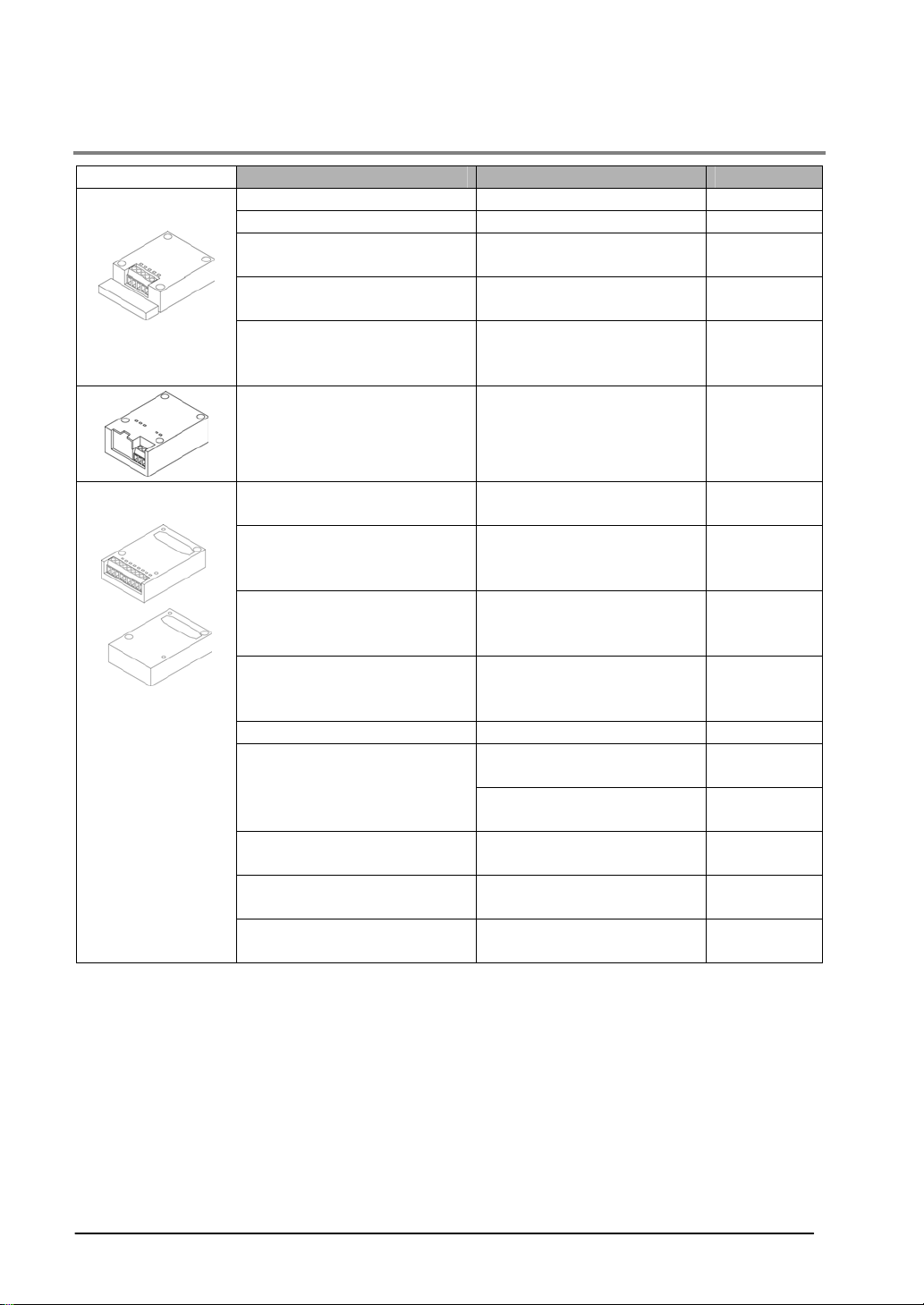
1.2.4 Add-on Cassettes (Communication cassettes/Application cassettes)
CTi Automation - Phone: 800.894.0412 - Fax: 208.368.0415 - Web: www.ctiautomation.net - Email: info@ctiautomation.net
Communication
cassette
Application
cassette
Name Specifications Product No.
FP-X Communication cassette 5-wire 1-channel RS232C AFPX-COM1
FP-X Communication cassette 3-wire 2-channel RS232C AFPX-COM2
FP-X Communication cassette
FP-X Communication cassette
FP-X Communication cassette
FP-X Communication cassette
FP-X Analog input cassette
FP-X Analog output cassette
FP-X Analog I/O cassette
FP-X Thermocouple cassette
FP-X Input cassette 8-point DC input AFPX-IN8
FP-X Output cassette
FP-X I/O cassette
FP-X Pulse I/O cassette
FP-X Master memory cassette
1-channel RS485/RS422
(insulated)
1-channel RS485 (insulated)
3-wire 1-channel RS232C
2-channel RS485
(non-insulated between
channels)
Ethernet,
3-wire 1-channel RS232C
2-channel analog input
(non-insulated)
2-channel analog output
(insulated) (non-insulated
between channels)
2-channel analog input
(insulated) + 1-channel
analog output (insulated)
2-channel thermocouple input
(insulated) (non-insulated
between channels)
8-point transistor output
(NPN)
6-point transistor output
(PNP)
4-point DC input + 3-point
transistor output (NPN)
2-ch high-speed counter +
1-ch pulse output
Master memory + realtime
clock
AFPX-COM3
AFPX-COM4
AFPX-COM6
AFPX-COM5
AFPX-AD2
AFPX-DA2
AFPX-A21
AFPX-TC2
AFPX-TR8
AFPX-TR6P
AFPX-IN4T3
AFPX-PLS
AFPX-MRTC
1-8
Page 23
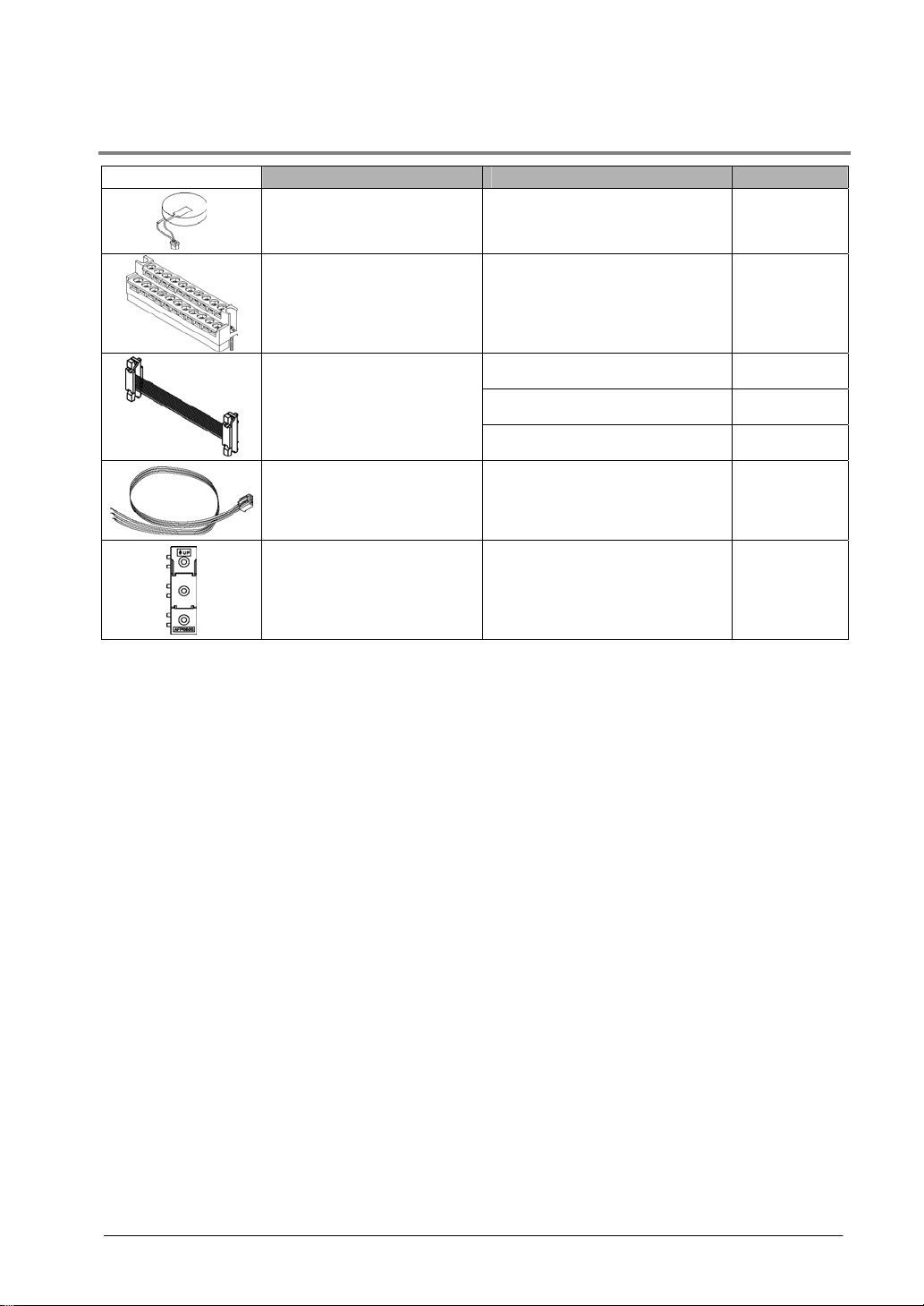
1.2.5 Related Parts
CTi Automation - Phone: 800.894.0412 - Fax: 208.368.0415 - Web: www.ctiautomation.net - Email: info@ctiautomation.net
Name Description Product No.
Necessary fro the backup of
FP-X Backup battery
data registers, etc. or for using
the realtime clock function.
For C30/C60 control unit
FP-X terminal block
(C30/C60)
for E30 expansion I/O unit
with 21-pin cover (no printing)
4 pcs/pack
8 cm AFPX-EC08
FP-X expansion cable
FP0 power supply cable
FP0 mounting plate
(slim type)
Note)
30 cm AFPX-EC30
80 cm AFPX-EC80
For Expansion FP0 adapter,
Length: 1 m
Used for expansion FP0
adapter and FP0 Expansion
unit, 10 pcs/pack
Note) The total length of the exapansion cable should be within 160 cm.
AFPX-BATT
AFPX-TAN1
AFP0581
AFP0803
1-9
Page 24

1.3 Restrictions on Unit Combinations
CTi Automation - Phone: 800.894.0412 - Fax: 208.368.0415 - Web: www.ctiautomation.net - Email: info@ctiautomation.net
1.3.1 Restrictions on FP-X Expansion Unit
Controllable I/O points
Type of control unit
FP-X C14 Control unit 14 points Max. 254 points
FP-X C30 Control unit 30 points Max. 270 points
FP-X C60 Control unit 60 points Max. 300 points
Number of I/O points when
using control unit
Number of I/O points when
using 8 units of E30
expansion I/O unit
Note:
- Up to eight units of FP-X can be connected, however, the restrictions on each expansion unit vary.
- For AFPX-E16: Two units cannot be connected consecutively since the power should be supplied from
the unit with the power supply (as no power supply is built in AFPX-E16).
E16 expansion I/O unit cannot be connected on the right side of the control unit or AFPX-E30.
- For AFPX-E30: There is no restriction on AFPX-E30 so that up to 8 units can be connected
consecutively.
- The total length of the expansion cable should be within 160 cm.
1-10
Page 25
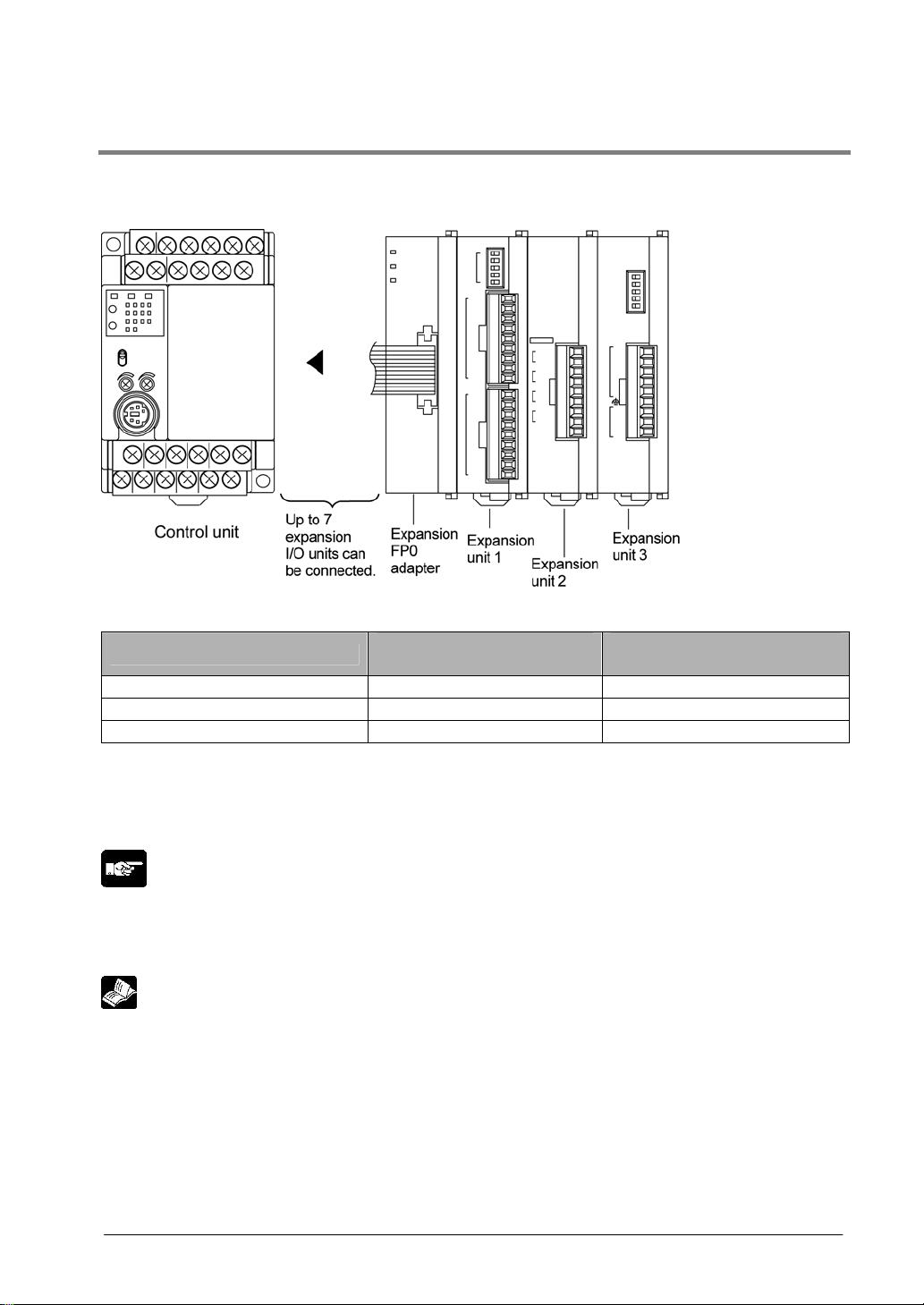
1.3.2 Restrictions on FP0 Expansion Unit
CTi Automation - Phone: 800.894.0412 - Fax: 208.368.0415 - Web: www.ctiautomation.net - Email: info@ctiautomation.net
Up to three dedicated FP0 expansion units can be added using the FP- X and the expansion FP0 adapter.
The relay output type and the transistor output type can be used in combination.
Controllable I/O points
Type of control unit
FP-X C14 Control unit 14 points Max. 110 points
FP-X C30 Control unit 30 points Max. 126 points
FP-X C60 Control unit 60 points Max. 156 points
Note1) Up to seven FP-X expansion I/O units can be also installed between the control unit and the
expansion FP0 adapter.
Note2) Only one expansion FP0 adapter can be installed at the last position of the FP-X expansion bus.
(It should be installed at the right hand side of the AFPX-E16 and E30.)
Note:
• Install the FP0 thermocouple unit on the right side of other expansion units. If it is installed on the left
side, the total precision will deteriorate.
• Install the FP0 CC-Link slave unit on the right side of the other expansion units. There is no expansion
connector on the right side.
Reference: For the details, <FP0 Thermocouple Unit Manual ARCT1F366E>
<FP0 CC-Link Slave Unit Manual ARCT1F380E>
Number of I/O points when
using control unit
Number of I/O points when
using FP0 expansion unit
1-11
Page 26

1.3.3 Restrictions on FP-X Add-on Cassette
CTi Automation - Phone: 800.894.0412 - Fax: 208.368.0415 - Web: www.ctiautomation.net - Email: info@ctiautomation.net
The add-on cassette is installed in the cassette mounting part 1 and 2 (only the cassette mounting part 1
is available for C14) of the control unit.
1-12
Page 27

Commu-
CTi Automation - Phone: 800.894.0412 - Fax: 208.368.0415 - Web: www.ctiautomation.net - Email: info@ctiautomation.net
nication
cassette
Application
cassette
A: Available, N/A: Not available
Restrictions on control unit
Type of add-on cassette
FP-X C14
FP-X C30
FP-X C60
Cassette
mounting
part 1
FP-X C30
FP-X C60
Cassette
mounting
part 2
FP-X C60
Expansion
connector
part
FP-X Communication cassette AFPX-COM1 A N/A
FP-X Communication cassette AFPX-COM2 A N/A
FP-X Communication cassette AFPX-COM3 A N/A
FP-X Communication cassette AFPX-COM4 A N/A
FP-X Communication cassette AFPX-COM5 A N/A
FP-X Communication cassette AFPX-COM6 A N/A
FP-X Analog input cassette AFPX-AD2 A A
FP-X Input cassette AFPX-IN8 A A
FP-X Analog output cassette AFPX-DA2 A A
FP-X Analog I/O cassette AFPX-A21 A A
The add-on
cassette
cannot be
installed.
FP-X Thermocouple cassette AFPX-TC2 A A
FP-X Output cassette AFPX-TR8 A A
FP-X Output cassette AFPX-TR6P A A
FP-X I/O cassette AFPX-IN4T3 A A
FP-X Pulse I/O cassette AFPX-PLS A
FP-X Master memory cassette AFPX-MTRC A
Note5)
A
Note1)
A
Note5)
Note1)
Note:
1. Only one FP-X master memory cassette AFPX-MRTC can be installed. If 2 units are installed, E26
(user ROM error) will occur.
2. One application cassette can be installed in either cassette mounting part 1 or 2 of C30/C60.
3. As only one communication cassette can be installed in the cassette mounting part 1, it should be
installed on on the application cassette if the application cassette is installed. (It cannot be installed in
the cassette mounting part 2.)
4. The add-on cassette cannot be installed in the expansion connector part of C60 (it does not work).
5. The pulse I/O cassette cannot be installed on the FP-X Tr type.
1-13
Page 28
1.4 Programming Tools
CTi Automation - Phone: 800.894.0412 - Fax: 208.368.0415 - Web: www.ctiautomation.net - Email: info@ctiautomation.net
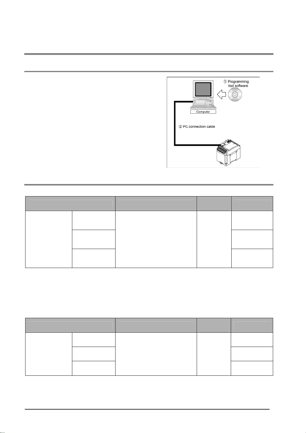
1.4.1 Tools Needed for Programming
1. Programming tool software
• The tool software can also be used with the FP
series.
• “FPWIN Pro Ver.5” or “FPWIN GR Ver.2”
Windows sorware is used with FP-X.
FPWIN GR Ver.1x, NPST-GR and FP
Programmer cannot be used.
2. PC connection cable
• The connection cable for DOS/V machine is
available.
• A commercial USB cable can be used for the
connection for C30/C60 control unit.
1.4.2 Software Environment and Suitable Cable
Standard ladder diagram tool software FPWIN-GR Ver.2
Type of software OS (Operating system)
Hard disk
capacity
Product No.
Full type AFPS10520
FPWIN GR Ver.2
English-
Small type AFPS11520
language menu
Upgrade
version
Note1) Ver.1.1 must be installed to install the upgrade version.
Note2) Ver.2.0 can be upgraded to the latest version after Ver. 2.1 free of charge at our web site
(http://www.mew.co.jp/ac/e/). Use the latest version.
Note3) The small type can be used only for each series of FP-e, FPΣ, FP0, FP-X, FP1 and FP-M.
Note4) A USB cable cannot be used when using Windows®95.
Conforms to IEC61131-3 programming tool software FPWIN-Pro Ver.5
Type of software OS (Operating system)
FPWIN Pro
Ver.5
Englishlanguage menu
Note1) The small type can be used only for each series of FP-e, FPΣ, FP0, FP-X, FP1 and FP-M.
Note2) Ver.4 must be installed to install the upgrade version.
Note3) Ver.5.0 can be upgraded to the latest version after Ver. 5.1 free of charge at our web site
(
http://www.mew.co.jp/ac/e/). Use the latest version.
Full type AFPS50550
Small type AFPS51550
Upgrade
version
Windows®95 (OSR 2 or later)
Windows®98
Windows®Me
WindowsNT® (Ver. 4 or later)
Windows®2000
Windows®XP
Windows®95 (OSR 2 or later)
Windows®98
Windows®Me
WindowsNT® (Ver. 4 or later)
Windows®2000
Windows®XP
40MB or
more
Hard disk
capacity
100MB or
more
AFPS10520R
Product No.
AFPS50550R
1-14
Page 29

Type of computer and suitable cable
CTi Automation - Phone: 800.894.0412 - Fax: 208.368.0415 - Web: www.ctiautomation.net - Email: info@ctiautomation.net
For the connection between a personal computer (RS232C) and the control unit (RS232C)
PC side connector PLC side connector Specifications Product No.
D-sub 9-pin
Note) A USB/RS232C conversion cable is necessary to connect with a personal computer without a
serial port using a PC connection cable.
female-Mini DIN round 5-pin L type (3 m) AFC8503
female-Mini DIN round 5-pin Straight type (3 m) AFC8503S
For the connection between a personal computer (USB) and the control unit (USB)
USB cable (For C30 and C60 only)
Use a commercial cable.
Cable type Length
USB 2.0 (or 1.1) AB type Max. 5 m
Reference: <Chapter 6 Tool Port and USB Port>
1-15
Page 30

CTi Automation - Phone: 800.894.0412 - Fax: 208.368.0415 - Web: www.ctiautomation.net - Email: info@ctiautomation.net
1-16
Page 31

CTi Automation - Phone: 800.894.0412 - Fax: 208.368.0415 - Web: www.ctiautomation.net - Email: info@ctiautomation.net
Chapter 2
Specifications and Functions of Control
Unit
Page 32

2.1 Parts and Functions
CTi Automation - Phone: 800.894.0412 - Fax: 208.368.0415 - Web: www.ctiautomation.net - Email: info@ctiautomation.net
2.1.1 Parts and Functions
2-2
Page 33

Status indicator LEDs
CTi Automation - Phone: 800.894.0412 - Fax: 208.368.0415 - Web: www.ctiautomation.net - Email: info@ctiautomation.net
These LEDs display the current mode of operation or the occurrence of an error.
LED LED and operation status
Lights when in the RUN mode and indicates that the program is
RUN Green
PROG. Green
ERROR/
ALARM
Input/output indicator LEDs
Indicates the on/off status of the input and output.
RUN/PROG. mode switch
This switch is used to change the operation mode of the PLC.
Switch position Operation mode
RUN (upward)
PROG. (downword) This sets the PROG. mode. The operation stops.
• The remote switching operation from the programming tool is operable.
• When performing remote switching from the programming tool, the setting of the mode switch and the
actual mode of operation may differ. Verify the mode with the status indicator LED.
• Restart FPΣ to operate in the mode set with the RUN/PROG. mode switch.
USB connector (B type)
Red
This sets the RUN mode. The program is executed is executed and operation
begins.
being executed.
It flashes during forced input/output. (The RUN and PROG. LEDs
flash alternately.)
Lights when in the PROG. Mode and indicates that operation has
stopped.
Lights when in the PROG. Mode during forced input/output.
It flashes during forced input/output. (The RUN and PROG. LEDs
flash alternately.)
Flashes when an error is detected during the self-diagnostic
function. (ERROR)
Lights if a hardware error occurs, or if oepration slows because of
the program, and the watchdog timer is activated. (ALARM)
This is a connector to connect the programming tool.
Commercial USB cables (AB type) can be used.
• The baud rate with the USB is 115.2 kbps (fixed).
• Either USB port or COM2 port of 2-channnel type communication
cassette is selected.
The USB port cannot be used when the COM2 port is used.
Reference: <Chapter 6 Tool Port and USB Port>
<7.1.6 About USB Port>
Analog potentiometer (analog dial)
Turning this dial chanes the values of special data registers DT90040 to DT90043 within the range of K0
to K1000. It can be used for analog timers and other applications.
C14R and C30R equips 2 points and C60R equips 4 points.
Expample: <12.4 Analog potentiometer>
2-3
Page 34

Tool port (RS232C)
CTi Automation - Phone: 800.894.0412 - Fax: 208.368.0415 - Web: www.ctiautomation.net - Email: info@ctiautomation.net
This port is used to connect a programming tool.
A commercial mini-DIN 5-pin connector is used for the Tool port on the control unit.
Pin No. Signal name Abbreviation Signal direction
1 Signal Ground SG −
2 Send Data SD Unit → External device
3 Receive Data RD Unit ← External device
4 (Not used) − −
The followings are the default settings set when the unit is shipped from the factory. The system register
“Tool port setting” should be used to change these.
- Baud rate …….. 9600 bps
- Character bit …. 8 bit
- Parity check ….. Odd parity
- Stop bit length .. 1 bit
Note) The unit numbers (station numbers) of the tool port should be specified using the system register
“Tool port setting”.
5 +5V +5V Unit → External device
Power supply and input terminal block
This is the power supply and input wiring terminal. A solderless terminal for M3 can be used.
Service power supply for input and output terminal block
This is the service power supply for input and output wiring terminal. A solderless terminal for M3 can be
used.
Reference: <5.7 Wiring of Terminal Block>
Expansion cover
It is used after the expansion cable and the battery has been installed.
Add-on cassette connector
Reference: <5.4 How to Install Add-on Cassette>
Connector For connecting expansion I/O unit and expansion FP0 adapter
An exclusive expansion cable is inserted.
Reference: <5.2 Installation Using Expansion Cable>
Battery cover
This battery cover is removed when the optional backup battery is installed.
Installing the backup battery enables the backup of the realtime clock or data registers.
Reference: <5.9 Installation and Setting of Backup Battery >
<12.2.1 Realtime Clock Function>
DIN rail attachment lever
This lever enables the units to attach to a DIN rail at a touch.
2-4
Page 35

2.2 Power Supply Specifications
CTi Automation - Phone: 800.894.0412 - Fax: 208.368.0415 - Web: www.ctiautomation.net - Email: info@ctiautomation.net
2.2.1 AC Power Supply
Item
Rated voltage 100 to 240 V AC
Voltage regulation range 85 to 264 V AC
Surge current 40 A or less (at 240 V AC, 25 °C) 45 A or less (at 240 V AC, 25 °C)
Momentary power off time 10 ms (when using 100 V AC)
Frequency 50/60 Hz (47 to 63 Hz)
Leakage current 0.75 mA or less between input and protective earth terminals
Internal power supply part
Guaranteed life
Fuse Built-in (Cannot be replaced)
Insulation system Transformer insulation
Terminal screw M3
20,000 hours (at 55 °C)
C14 C30R/C60
Specifications
2.2.2 Service Power Supply for Input (Output) (AC Power Supply Type Only)
Item
Rated output voltage 24 V DC
Voltage regulation range 21.6 to 26.4 V DC
Rated output current 0.15 A 0.4 A
Overcurrent protection
function
Terminal screw M3
Note) This is a function to protect overcurernt temporarily, which protects the output short-circuit. If the
Note)
short-circuit is detected, all the power supply for the PLC will be turned off. If a current load that is
out of the specifications is connected and the overloaded status continues, it may lead to damages.
Available
C14 C30/C60
Specifications
2.2.3 DC Power Supply
Item
Rated voltage 24 V DC
Voltage regulation range 20.4 to 28.8 V DC
Inrush current 12 A or less (at 25 °C)
Momentary power off time 10 ms
Internal power supply part
Guaranteed life
Fuse Built-in (Cannot be replaced)
Insulation system Transformer insulation
Terminal screw M3
20,000 h (at 55 °C)
C14 C30/C60
2-5
Specifications
Page 36

2.3 Input Specifications
CTi Automation - Phone: 800.894.0412 - Fax: 208.368.0415 - Web: www.ctiautomation.net - Email: info@ctiautomation.net
2.3.1 Relay (Ry) Type
Input Specifications (For C14R/C30R/C60R control units)
Item Description
Insulation method Optical coupler
Rated input voltage 24V DC
Operating voltage range 21.6 to 26.4V DC
Rated inptu current
Input points per common
Min. on voltage/Min. on current 19.2 V DC/3 mA
Max. off voltage/Max. off current 2.4V DC/1 mA
Input impedance
Response time
Operating mode indicator LED display
EN61131-2 Applicable type TYPE3 (however, according to the above specifications)
Note) this specification is applied when the rated input voltage is 24 V DC and the temperature is 25 °C.
Circuit diagram
off→on
on→off Same as above
Approx. 4.7 mA (for control units X0 to X7)
Approx. 4.3 mA (from control unit X8 )
8 points/common (C14R)
16 points/common (C30R/C60R)
(Either the positive or negative of the input power supply can be
connected to common terminal.)
Approx. 5.1 kΩ (for control units X0 to X7)
Approx. 5.6 kΩ (from control unit X8 )
For control units X0 to X7:
0.6 ms or less: normal input
50 μs or less: high-speed counter, pulse catch, interrupt
input settings
From control unit X8 :
0.6 ms or less
Note)
For X0 to X7: R1=5.1 kΩ R2=3 kΩ
From X8: R1=5.6 kΩ R2=1 kΩ
Limitations on number of simultaneous input on points
Reference: <2.5 Limitations on Number of Simultaneous Input/Output On Points>
2-6
Page 37

2.3.2 Transistor (Tr) Type (Common to NPN and PNP)
CTi Automation - Phone: 800.894.0412 - Fax: 208.368.0415 - Web: www.ctiautomation.net - Email: info@ctiautomation.net
Transistor type (common to NPN and PNP)
Item
C14 C30/C60
Insulation method Optical coupler
Rated input voltage 24V DC
Operating voltage range 21.6 to 26.4V DC
Approx. 8 mA (for control units X0 to X3)
Rated input current
Approx. 4.7 mA (for control units X4 to X7)
Approx. 4.3 mA (from control unit X8)
8 points/common 16 points/common
Input points per common
(Either the positive or negative of the input power supply can be
connected to common terminal.)
Min. on voltage/Min. on current
Max. off voltage/Max. off current
19.2 V DC/6 mA (for control units X0 to X3)
19.2 V DC/3 mA (from control unit X4)
2.4V DC/1.3 mA (for control units X0 to X3)
2.4V DC/1 mA (from control unit X4)
Approx. 3 kΩ (for control units X0 to X3)
Input impedance
Approx. 5.1 kΩ (for control units X4 to X7)
Approx. 5.6 kΩ (from control unit X8 )
For control units X0 to X3:
135 μs or less: normal input
5 μs or less
Note)
: high-speed counter, pulse catch,
interrupt input settings
For control units X4 to X7:
135 μs or less: normal input
50 μs or less
Note)
Response time
off→on
From control unit X8 (C30/C60 only) :
0.6 ms or less
on→off Same as above
Operating mode indicator LED display
EN61131-2 Applicable type TYPE3 (however, according to the above specifications)
Note) this specification is applied when the rated input voltage is 24 V DC and the temperature is 25 °C.
Circuit diagram
[X0 to X3] [From X4]
Description
: high-speed counter, pulse catch,
interrupt input settings
X4 to X7 :R1=5.1kΩ R2=3kΩ
From X8 :R1=5.6kΩ R2=1kΩ
Limitations on number of simultaneous input on points
Reference: <2.5 Limitations on Number of Simultaneous Input/Output On Points>
2-7
Page 38

2.4 Output Specifications
CTi Automation - Phone: 800.894.0412 - Fax: 208.368.0415 - Web: www.ctiautomation.net - Email: info@ctiautomation.net
2.4.1 Relay (Ry) Type
Relay output specifications (For C14R/C30R/C60R control units)
Item
Insulation method Relay insulation
Output type 1a output (Relay cannot be replaced)
2 A 250 V AC, 2 A 30 V DC
Rated control capacity
Output points per common 1 point/common, 2 points/common, 3 points/common, 4 points/common
Response time
Mechanical
Lifetime
Surge absorber
Operating mode indicator
Note1) Resistance load
Circuit diagram
Electrical
Note)
(6 A or less/common) (8 A or less/common)
off→on Approx. 10 ms
on→off Approx. 8 ms
20 million times or more (Frequency of switching: 180 times/min.)
100 thousand times or more (Frequency of switching at the rated control
capacity: 20 times/min.)
None
LED display
C14 C30/C60
Description
Limitations on number of simultaneous input on points
Reference: <2.5 Limitations on Number of Simultaneous Input/Output On Points>
2-8
Page 39

2.4.2 Transistor (Tr) Type (NPN)
CTi Automation - Phone: 800.894.0412 - Fax: 208.368.0415 - Web: www.ctiautomation.net - Email: info@ctiautomation.net
Output specifications
Item
Insulation method Optical coupler
Output type Open collector
Rated load voltage 5 to 24 V DC
Allowable load voltage
range
Max. load current 0.5 A
Max. inrush current 1.5 A
Input points per
common
Off state leakage
current
On state voltage drop 0.3 V DC or less
OFF→ON
Response
time
(at 25°C)
ON→OFF
External power supply
(+ and – terminals)
Surge absorber Zener diode
Operating mode
indicator
4.75 to 26.4 V DC
6 points/Common 8 points/Common, 6 points/Common
1 μA or less
2 μs or less (Y0 to Y3) (Load current: at 15 mA or more)
20 μs or less (C14: Y4 to Y5, C30/C60: Y4 to Y7)(Load current: at 15 mA or
more)
1 ms or less (C14: None, C30/C60: from Y8)
8 μs or less (Y0 to Y3) (Load current: at 15 mA or more)
30 μs or less (C14: Y4 to Y5, C30/C60: Y4 to Y7)
1 ms or less (C14: None, C30/C60: from Y8)
Voltage 21.6 to 26.4 V DC
Current
LED display
C14 C30/C60
(Load current: at 15 mA or more)
Y0 to Y5 (Y7) Y8 to YD Y10 to Y17 Y18 to Y1D
40 mA
C14
or less
60 mA
C30
or less
60 mA
C60
or less
Circuit diagram
[NPN output]
[X0 to X3] [From X4]
Description
35 mA
or less
35 mA
or less
⎯ ⎯ ⎯
⎯ ⎯
45 mA
or less
35 mA
or less
Limitations on number of simultaneous input on points
Reference: <2.5 Limitations on Number of Simultaneous Input/Output On Points>
2-9
Page 40

2.4.3 Transistor (Tr) Type (PNP)
CTi Automation - Phone: 800.894.0412 - Fax: 208.368.0415 - Web: www.ctiautomation.net - Email: info@ctiautomation.net
Output specifications
Item
Insulation method Optical coupler
Output type Open collector
Rated load voltage 24 V DC
Allowable load voltage
range
Max. load current 0.5 A
Max. inrush current 1.5 A
Input points per common 6 points/Common 8 points/Common, 6 points/Common
Off state leakage current 1 μA or less
On state voltage drop 0.5 V DC or less
OFF→ON
time
ON→OFF
External power supply
(+ and – terminals)
Surge absorber Zener diode
Operating mode indicator LED display
21.6 to 26.4 V DC
2 μs or less (Y0 to Y3) (Load current: at 15 mA or more)
20 μs or less (C14: Y4 to Y5, C30/C60: Y4 to Y7)
1 ms or less (C14: None, C30/C60: from Y8) Response
8 μs or less (Y0 to Y3) (Load current: at 15 mA or more)
30 μs or less (C14: Y4 to Y5, C30/C60: Y4 to Y7)
1 ms or less (C14: None, C30/C60: from Y8)
Voltage 21.6 to 26.4 V DC
Current
C14 C30/C60
(Load current: at 15 mA or more)
(Load current: at 15 mA or more)
Y0 to Y5 (Y7) Y8 to YD Y10 to Y17 Y18 to Y1D
75 mA
C14
or less
95 mA
C30
or less
95 mA
C60
or less
Circuit diagram
[PNP output]
[Y0 to Y3] [from Y4]
Description
⎯ ⎯ ⎯
50 mA
or less
50 mA
or less
⎯ ⎯
65 mA
or less
50 mA
or less
Limitations on number of simultaneous input on points
Reference: <2.5 Limitations on Number of Simultaneous Input/Output On Points>
2-10
Page 41

2.5 Limitations on Number of Simultaneous Input/Output
CTi Automation - Phone: 800.894.0412 - Fax: 208.368.0415 - Web: www.ctiautomation.net - Email: info@ctiautomation.net
On Points
2.5.1 Relay (Ry) Type
Keep the number of points which are simultaneously on within the following range as determined by the
ambient temperature.
Product number
AFPX-C14R
Limitations on number of
simultaneous input on points
Limitations on number of
simultaneous output on points
AFPX-C30R
AFPX-C60R
AFPX-C14RD
AFPX-C30RD
AFPX-C60RD
2-11
Page 42

2.5.2 Transistor (Tr) Type (NPN)
CTi Automation - Phone: 800.894.0412 - Fax: 208.368.0415 - Web: www.ctiautomation.net - Email: info@ctiautomation.net
Keep the number of points which are simultaneously on within the following range as determined by the
ambient temperature.
Product number
AFPX-C14T
Limitations on number of
simultaneous input on points
Limitations on number of
simultaneous output on points
AFPX-C30T
AFPX-C60T
AFPX-C14TD
AFPX-C30TD
AFPX-C60TD
2-12
Page 43

2.5.3 Transistor (Tr) Type (PNP)
CTi Automation - Phone: 800.894.0412 - Fax: 208.368.0415 - Web: www.ctiautomation.net - Email: info@ctiautomation.net
Keep the number of points which are simultaneously on within the following range as determined by the
ambient temperature.
Product number
AFPX-C14P
Limitations on number of
simultaneous input on points
Limitations on number of
simultaneous output on points
AFPX-C30P
AFPX-C60P
AFPX-C14PD
AFPX-C30PD
AFPX-C60PD
2-13
Page 44

2.6 Terminal Layout
CTi Automation - Phone: 800.894.0412 - Fax: 208.368.0415 - Web: www.ctiautomation.net - Email: info@ctiautomation.net
2.6.1 Relay Type
AFPX-C14R AFPX-C14RD
AFPX-C30R
AFPX-C30RD
2-14
Page 45

AFPX-C60R
CTi Automation - Phone: 800.894.0412 - Fax: 208.368.0415 - Web: www.ctiautomation.net - Email: info@ctiautomation.net
AFPX-C60RD
Key Point:
Input terminal:
Each COM terminal in the same terminal block is connected within the unit.
However, the COM terminals of the input terminals 1 and 2 for C60 are isolated. (They are not
connected internally.)
Output terminal:
Each COM port (CO, C1 …) is separate. Use them in the range surrounded by the bold black lines.
2-15
Page 46

2.6.2 Transistor type
CTi Automation - Phone: 800.894.0412 - Fax: 208.368.0415 - Web: www.ctiautomation.net - Email: info@ctiautomation.net
AFPX-C14T
AFPX-C14P
AFPX-C14TD
2-16
Page 47

AFPX-C14PD
CTi Automation - Phone: 800.894.0412 - Fax: 208.368.0415 - Web: www.ctiautomation.net - Email: info@ctiautomation.net
AFPX-C30T
AFPX-C30P
2-17
Page 48

AFPX-C30TD
CTi Automation - Phone: 800.894.0412 - Fax: 208.368.0415 - Web: www.ctiautomation.net - Email: info@ctiautomation.net
AFPX-C30PD
AFPX-C60T
2-18
Page 49

AFPX-C60P
CTi Automation - Phone: 800.894.0412 - Fax: 208.368.0415 - Web: www.ctiautomation.net - Email: info@ctiautomation.net
AFPX-C60TD
AFPX-C6PD
Key Point:
Input terminal:
Each COM terminal in the same terminal block is connected within the unit.
However, the COM terminals of the input terminals 1 and 2 for C60 are isolated. (They are not
connected internally.)
Output terminal:
Each power supply terminal is separate. Use them in the range surrounded by the bold black lines.
2-19
Page 50

CTi Automation - Phone: 800.894.0412 - Fax: 208.368.0415 - Web: www.ctiautomation.net - Email: info@ctiautomation.net
2-20
Page 51

CTi Automation - Phone: 800.894.0412 - Fax: 208.368.0415 - Web: www.ctiautomation.net - Email: info@ctiautomation.net
Chapter 3
Expansion Cassette and Expansion FP0
Adapter Specifications
Page 52

3.1 Expansion Method
CTi Automation - Phone: 800.894.0412 - Fax: 208.368.0415 - Web: www.ctiautomation.net - Email: info@ctiautomation.net
Two types of expansion method are available for the FP-X.
1. Installs the FP-X expansion unit or FP0 expansion unit (expandion FP0 adapter) using the
expansion cable.
2. Installs the add-on cassette to the cassette mounting part of the FP-X control unit.
3.1.1 Expansion Using the Expansion Cable
For the FP-X, the FP-X expansion unit and the FP0 expansion unit (expansion FP0 adapter AFPX-EFP0
is necessary) can be used by using the exclusive expansion cable.
Note:
Note1) Up to seven FP-X expansion I/O units can be also installed between the control unit and the
expansion FP0 adapter.
Note2) Only one expansion FP0 adapter can be installed at the last position of the FP-X expansion bus.
(It should be installed at the right hand side of the AFPX-E16 and E30.)
3-2
Page 53

CTi Automation - Phone: 800.894.0412 - Fax: 208.368.0415 - Web: www.ctiautomation.net - Email: info@ctiautomation.net
3-3
Page 54

3.2 FP-X Expansion Unit
CTi Automation - Phone: 800.894.0412 - Fax: 208.368.0415 - Web: www.ctiautomation.net - Email: info@ctiautomation.net
3.2.1 Parts and Functions
FP-X E16 exapansion I/O unit
FP-X E30 exapansion I/O unit
Input and Output indicator LEDs
Indicates the on/off status of the input and output.
Input terminal block
This is the input terminal. A solderless terminal for M3 can be used.
Output terminal block
This is the output terminal. A solderless terminal for M3 can be used.
Reference: <5.7 Wiring of Terminal Block>
Expansion connector
Connects with the control unit, expansion unit and the expansion FP0 adapter using the exclusive
expansion cable.
Expansion cover
It is used after the expansion cable has been fitted.
DIN rail attachment lever
This lever enables the expansion unit to attach to a DIN rail at a touch.
Terminator setting DIP switch
All switches should be turned on for the expansion unit installed at the last position .
3-4
Page 55

3.2.2 Power Supply Specifications
CTi Automation - Phone: 800.894.0412 - Fax: 208.368.0415 - Web: www.ctiautomation.net - Email: info@ctiautomation.net
AC Power Supply
Item
Rated voltage 100 to 240 V AC
Voltage regulation range 85 to 264 V AC
Inrush current 40 A or less (at 240 V AC, 25 °C)
Momentary power off time 10 ms (when using 100 V AC)
Frequency 50/60 Hz (47 to 63 Hz)
Leakage current 0.75 mA or less between input and protective earth terminals
Internal power supply part
Guaranteed life
Fuse Built-in (Cannot be replaced)
Insulation system Transformer insulation
Terminal screw M3
Service Power Supply for Input (Output) (AC power supply type only)
Item
Rated output voltage 24 V DC
Voltage regulation range 21.6 to 26.4 V DC
Rated output current 0.4 A
Overcurrent protection
function
Terminal screw M3
Note) This is a function to protect overcurernt temporarily. If a current load that is out of the
Note)
specifications is connected, it may lead to damages.
20,000 hours (at 55 °C)
Available
DC Power Supply
Item
Rated voltage 24 V DC
Voltage regulation range 20.4 to 28.8 V DC
Inrush current 12 A or less (at 25 °C)
Momentary power off time 10 ms
Internal power supply part
Guaranteed life
Fuse Built-in (Cannot be replaced)
Insulation system Transformer insulation
Terminal screw M3
20,000 hours (at 55 °C)
Specifications
E30
Specifications
E30
Specifications
E30
3-5
Page 56

3.2.3 Input and output specifications
CTi Automation - Phone: 800.894.0412 - Fax: 208.368.0415 - Web: www.ctiautomation.net - Email: info@ctiautomation.net
Input specifications
Item
Insulation method Optical coupler
Rated input voltage 24 V DC
Operating voltage range 21.6 to 26.4 V DC
Rated input current Approx. 4.3 mA
8 points/common 16 points/common
Input points per common
Min. on voltage/Min. on current 19.2 V DC/3 mA
Max. off voltage/Max. off current 2.4 V DC/1 mA
Input impedance Approx. 5.6 kΩ
Response time
Operating mode indicator LED display
EN61131-2Applicable type
Circuit diagram
off→on 0.6 ms or less
on→off 0.6 ms or less
(Either the positive or negative of input power supply can be
connected to common terminal.)
TYPE3 (however, according to the above specifications)
E16 E30
Description
: R1=5.6 kΩ R2=1 kΩ
Relay output specifications
Item
Insulation method Relay insulation
Output type 1a output (Relay cannot be replaced.)
Output points per common 1 point/common,
Response time
Lifetime
Surge absorber None
Operating mode indicator LED display
Note) Resistance load
Circuit diagram
Note)
off→on Approx. 10 ms
on→off Approx. 8 ms
Mechanical 20 million times or more (Frequency of switching: 180 times/min.)
Electrical
2 A 250 V AC, 2 A 30 V DC Rated control capacity
(6 A or less/common) (8 A or less/common)
3 points/common
100 thousand times or more (Frequency of switching at the rated
control capacity: 20 times/min.)
Description
E16 E30
1 point/common,
4 points/common
3-6
Page 57

Transistor type (NPN)
CTi Automation - Phone: 800.894.0412 - Fax: 208.368.0415 - Web: www.ctiautomation.net - Email: info@ctiautomation.net
Item
Insulation method Optical coupler
Output type Open collector
Rated load voltage 5 to 24 V DC
Allowable load voltage range 4.75 to 26.4 V DC
Max. load current 0.5 A
Max. inrush current 1.5 A
Input points per common 8 points/Common
Off state leakage current 1 μA or less
On state voltage drop 0.3 V DC or less
Response time
External power supply
(+ and – terminals)
Surge absorber Zener diode
Operating mode indicator LED display
OFF→ON 1 ms or less
ON→OFF 1 ms or less
Voltage 21.6 to 26.4 V DC
Current
Y0 to Y7 Y8 to YD
E16 45 mA or less ⎯
E30 45 mA or less 35 mA or less
Circuit diagram
Description
E16 E30
8 points/Common,
6 points/Common
3-7
Page 58

Transistor type (PNP)
CTi Automation - Phone: 800.894.0412 - Fax: 208.368.0415 - Web: www.ctiautomation.net - Email: info@ctiautomation.net
Item
Insulation method Optical coupler
Output type Open collector
Rated load voltage 24 V DC
Allowable load voltage range 21.6 to 26.4 V DC
Max. load current 0.5 A
Max. inrush current 1.5 A
Input points per common 8 points/Common
Off state leakage current 1 μA or less
On state voltage drop 0.5 V DC or less
Response time
External power supply
(+ and – terminals)
Surge absorber Zener diode
Operating mode indicator LED display
OFF→ON 1 ms or less
ON→OFF 1 ms or less
Voltage 21.6 to 26.4 V DC
Current
Y0 to Y7 Y8 to YD
E16 65 mA or less ⎯
E30 65 mA or less 50 mA or less
Circuit diagram
Description
E16 E30
8 points/Common,
6 points/Common
3-8
Page 59

3.2.4 Terminal layout
CTi Automation - Phone: 800.894.0412 - Fax: 208.368.0415 - Web: www.ctiautomation.net - Email: info@ctiautomation.net
AFPX-E16R
AFPX-E16T AFPX-E16P
AFPX-E30R
3-9
Page 60

AFPX-E30RD
CTi Automation - Phone: 800.894.0412 - Fax: 208.368.0415 - Web: www.ctiautomation.net - Email: info@ctiautomation.net
AFPX-E30T
AFPX-E30P
3-10
Page 61

AFPX-E30TD
CTi Automation - Phone: 800.894.0412 - Fax: 208.368.0415 - Web: www.ctiautomation.net - Email: info@ctiautomation.net
AFPX-E30PD
Input terminal:
Each COM terminal in the same terminal block is connected within the unit.
Output terminal:
Each COM terminal(CO, C1 …) of Ry type is separate.
Each power supply terminal of Tr type is separate. Use them in the range surrounded by the
bold black lines.
3-11
Page 62

3.3 FP-X Expansion FP0 Adapter
CTi Automation - Phone: 800.894.0412 - Fax: 208.368.0415 - Web: www.ctiautomation.net - Email: info@ctiautomation.net
3.3.1 Overview
For the FP-X, a maximum of 3 units of the FP0 expansion units (expansion I/O unit, intelligent unit) can
be used using the expansion FP0 adapter.
All FP0 expansion unit can be used.
- DC input unit
- Transistor output unit
- Relay output unit
- Analog I/O unit
- Thermocouple unit
- Network unit
Note:
The expansion FP0 adapter does not functionn by itself. Always connect the FP0 expansion unit to it.
Reference: For the information on the restrictions on the installation position,
<1.3.2 Restrictions on FP0 Expansion Unit>
For the information on each FP0 expansion unit,
<Each exclusive manual or FP0 User’s Manual ARCT1F389E>
3-12
Page 63

3.3.2 Parts and Functions
CTi Automation - Phone: 800.894.0412 - Fax: 208.368.0415 - Web: www.ctiautomation.net - Email: info@ctiautomation.net
FP-X expansion FP0 adapter (AFPX-EFP0)
Status indicator LEDs
LED
POWER Green When the power of 24 V DC is supplied and the communication starts with the
control unit, the LED lights. When the communication cannot be carried out, it
goes out.
I/F Green When the communication starts with the control unit, the LED lights. When the
communication cannot be carried out, it goes out.
When the FP0 expansion unit is not connected, it flashes.
ERROR Red When an error occurs on the connection with the FP0 expansion unit, it flashes.
FP-X expansion bus connector
Connects the FP-X control unit (or FP-X expansion unit). The provided expansion cable (AFPX-EC08) is
used for the connection.
It is not necessary to specify the TERM (terminal) setting for the expansion FP0 adapter.
Power supply connector (24V DC)
Supply the power of 24 V DC. The provided power supply cable (AFP0581) is used for the connection.
Supply the power from the service power supply for the input of the FP-X control unit.
FP0 expansion connector
Connects the FP0 expansion unit.
Expansion hook
This hook is used to secure the FP0 expansion unit.
DIN rail attachment lever
This lever enables the expansion unit to attach toa DIN rail at a touch. The lever is also used for
installation on the mounting plate slim type) (AFP0803).
General specifications
Item Specifications
Rated voltage 24 V DC
Voltage regulation 21.6 to 26.4 V DC
Surge current 20A or less (24 V DC, at 25 °C)
Fuse Built-in (Replacement is not available)
Insulation system Non-isolated
Power supply connector 3-pin connector (Power supply cable AFP0581 is provided.)
Reference:
For information on consumption current, <15.1 Table of Specifications ♦Unit’s current consumption
table>
3-13
Page 64

CTi Automation - Phone: 800.894.0412 - Fax: 208.368.0415 - Web: www.ctiautomation.net - Email: info@ctiautomation.net
3-14
Page 65

CTi Automation - Phone: 800.894.0412 - Fax: 208.368.0415 - Web: www.ctiautomation.net - Email: info@ctiautomation.net
Chapter 4
I/O Allocation
Page 66

4.1 I/O Allocation
CTi Automation - Phone: 800.894.0412 - Fax: 208.368.0415 - Web: www.ctiautomation.net - Email: info@ctiautomation.net
Input Output
Control unit X0 to X9F (WX0 to WX9) Y0 to Y9F (WY0 to WY9)
Cassette mounting part 1
(Slot 0)
Cassette mounting part 2
(Slot 1)
Expansion 1st unit X300 to X39F (WX30 to WX39) Y300 to Y39F (WY30 to WY39)
Expansion 2nd unit X400 to X49F (WX40 to WX49) Y400 to Y49F (WY40 to WY49)
Expansion 3rd unit X500 to X59F (WX50 to WX59) Y500 to Y59F (WY50 to WY59)
Expansion 4th unit X600 to X69F (WX60 to WX69) Y600 to Y69F (WY60 to WY69)
Expansion 5th unit X700 to X79F (WX70 to WX79) Y700 to Y79F (WY70 to WY79)
Expansion 6th unit X800 to X89F (WX80 to WX89) Y800 to Y89F (WY80 to WY89)
Expansion 7th unit X900 to X99F (WX90 to WX99) Y900 to Y99F (WY90 to WY99)
Expansion 8th unit
Note) The ranges of the I/O numbers which are actually used differ depending on the cassettes and units.
Regarding I/O number
• Specifying X and Y numbers
On the FP-X and the FP0, the same numbers are used for input and output.
• Expression of numbers for input/output relays
Input relay “X” and output relay “Y” are expressed as a combination of decimal and hexadecimal
numbers as shown below.
X100 to X19F (WX10 to WX19) Y100 to Y19F (WY10 to WY19)
X200 to X29F (WX20 to WX29) Y200 to Y29F (WY20 to WY29)
X1000 to X109F
(WX100 to WX109)
Y1000 to Y109F
(WY100 to WY109)
• Slot No.
Slot No. is the number indicating the installing position of the cassette which is used to generate
programs by the add-on cassette.
4-2
Page 67

4.2 Allocation of FP-X Control Unit
CTi Automation - Phone: 800.894.0412 - Fax: 208.368.0415 - Web: www.ctiautomation.net - Email: info@ctiautomation.net
The I/O allocation of FP-X control unit is fixed.
I/O numbers
Type of control unit Number of allocation I/O number
FP-X C14 control unit
FP-X C30 control unit
FP-X C60 control unit
Input (8 points) X0 to X7
Output (6 points) Y0 to Y5
Input (16 points) X0 to XF
Output (14 points) Y0 to YD
Input (32 points)
Output (28 points)
X0 to XF
X10 to X1F
Y0 to YD
Y10 to Y1D
4.3 FP0 Expansion Unit Allocation
The FP-X expansion unit is installed on the right side of the FP-X control unit.
I/O numbers (when installed as the first expansion unit)
Type of expansion unit Number of allo cation I/O number
FP-X E16 expansion I/O unit
FP-X E30 expansion I/O unit
Note) E16 cannot be connected on the right side of E16.
Input (8 points) X300 to X307
Output (8 points) Y300 to Y307
Input (16 points) X300 to X30F
Output (14 points) Y300 to Y30D
4-3
Page 68

4.4 Allocation of FP0 Expansion Unit
CTi Automation - Phone: 800.894.0412 - Fax: 208.368.0415 - Web: www.ctiautomation.net - Email: info@ctiautomation.net
4.4.1 I/O Allocation
The FP0 expansion unit is installed on the right side of the FP0 expansio n adapter.
The I/O numbers are allocated from the unit nearest to the expansion FP0 adapter in ascending order.
4.4.2 Number of Expansion Units and I/O Allocation
Only one expansion FP0 adapter can be connected at the last position of the FP-X expansion bus.
The I/O allocation varies depending on the installation location of the expansion FP0 adapter
Expansion location Expansion unit 1 Expansion unit 2 Expansion unit 3
Expansion 1st unit
Expansion 2nd unit
Expansion 3rd unit
Expansion 4th unit
Expansion 5th unit
Expansion 6th unit
Expansion 7th unit
Expansion 8th unit
Note) The ranges of the I/O numbers which are actually used differ depending on the units.
X300 to X31F X320 to X33F X340 to X35F
Y300 to Y31F Y320 to Y33F Y340 to Y35F
X400 to X41F X420 to X43F X440 to X45F
Y400 to Y41F Y420 to Y43F Y440 to Y45F
X500 to X51F X520 to X53F X540 to X55F
Y500 to Y51F Y520 to Y53F Y540 to Y55F
X600 to X61F X620 to X63F X640 to X65F
Y600 to Y61F Y620 to Y63F X640 to X65F
X700 to X71F X720 to X73F X740 to X75F
Y700 to Y71F Y720 to Y73F Y740 to Y75F
X800 to X81F X820 to X83F X840 to X85F
Y800 to Y81F Y820 to Y83F Y840 to Y85F
X900 to X91F X920 to X93F X940 to X95F
Y900 to Y91F Y920 to Y93F Y940 to Y95F
X1000 to X101F X1020 to X103F X1040 to X105F
Y1000 to Y101F Y1020 to Y103F Y1040 to Y105F
4-4
Page 69

4.4.3 I/O Allocation of FP0 Expansion Unit
CTi Automation - Phone: 800.894.0412 - Fax: 208.368.0415 - Web: www.ctiautomation.net - Email: info@ctiautomation.net
I/O do not need to be set as I/O allocation is performed automatically when an expansion unit is added.
The I/O allocation of expansion unit is determined by the installation location.
I/O numbers (when installed as the first expansion unit)
Carry the digit of hundreds place one by one since the second expansion unit.
Type of unit
FP0
Expansion unit
FP0 analog I/O
unit
FP0 A/D
conversion unit
FP0 thermocouple unit
FP0 D/A
conversion unit
I/O link unit
FP0-E8X Input (8 points) X300 to X307 X320 to X327 X340 to X347
FP0-E8R
FP0-E8YT/P
FP0-E8YR
FP0-E16X Input (16 points) X300 to X30F X320 to X32F X340 to X34F
FP0-E16R
FP0-E16T/P
FP0-E16YT/P Output (16 points) Y300 to Y30F Y320 to Y32F Y340 to Y34F
FP0-E32T/P
FP0-A21
FP0-A80
FP0-TC4
FP0-TC8
FP0-A04V
FP0-A04I
FP0-IOL
Number of
allocation
Input (4 points) X300 to X303 X320 to X323 X340 to X343
Output (4 points) Y300 to Y303 Y320 to Y323 Y340 to Y343
Output (8 points) Y300 to Y307 Y320 to Y327 Y340 to Y347
Input (8 points) X300 to X307 X320 to X327 X340 to X347
Output (8 points) Y300 to Y307 Y320 to Y327 Y340 to Y347
Input (16 points) X300 to X30F X320 to X32F X340 to X34F
Output (16 points) Y300 to Y30F Y320 to Y32F Y340 to Y34F
Input (16 points)
CH0
Input (16 points)
CH1
Output (16 points)
Input (16 points)
CH0, 2, 4, 6
Input (16 points)
CH1, 3, 5, 7
Input (16 points)
Output (16 points)
CH0, 2
Output (16 points)
CH1, 3
Input 32 points X300 to X31F X320 to X33F X340 to X35F FP0
Output 32 points Y300 to Y31F Y320 to Y33F Y340 to Y35F
• The data for the each channels of FP0 A/D conversion unit (FP0-A80), FP0 thermocouple unit (FP0TC4/FP0-TC8) and FP0 D/A conversion unit (FP0-A04V/FP0-A04I) is converted and loaded with a user
program that includes a switching flag to convert the data.
• Regarding FP0 CC-Link slave unit, please refer to the exclusive manual.
Expansion
unit 1
WX30
(X300 to X30F)
WX31
(X310 to X31F)
WY30
(Y300 to Y30F)
WX30
(X300 to X30F)
WX31
(X310 to X31F)
WX30
(X300 to X30F)
WY30
(Y300 to Y30F)
WY31
(Y310 to Y31F)
Expansion
unit 2
WX32
(X320 to X32F)
WX33
(X330 to X33F)
WY32
(Y320 to Y32F)
WX32
(X320 to X32F)
WX33
(X330 to X33F)
WX32
(X320 to X32F)
WY32
(Y320 to Y32F)
WY33
(Y330 to Y33F)
Expansion
unit 3
WX34
(X340 to X34F)
WX35
(X350 to X35F)
WY34
(Y340 to Y34F)
WX34
(X340 to X34F)
WX35
(X350 to X35F)
WX34
(X340 to X34F)
WY34
(Y340 to Y34F)
WY35
(Y350 to Y35F)
4-5
Page 70

4.5 I/O Allocation of FP-X Add-on Cassette
CTi Automation - Phone: 800.894.0412 - Fax: 208.368.0415 - Web: www.ctiautomation.net - Email: info@ctiautomation.net
The FP-X add-on cassette is mounted on the FP-X control unit.
I/O numbers
I/O No.
Type of control unit
Cassette
mounting part 1
Slot 0
Communication
cassette
Application
cassette
FP-X communication
cassette
FP-X communication
cassette
FP-X communication
cassette
FP-X communication
cassette
FP-X communication
cassette
FP-X communication
cassette
FP-X analog input
cassette
Note2)
FP-X analog output
cassette
FP-X analog I/O
cassette
FP-X thermocouple
cassette
FP-X input cassette AFPX-IN8 From X100 From X200
AFPX-COM1 − −
AFPX-COM2 − −
AFPX-COM3 − −
AFPX-COM4 − −
AFPX-COM5 − −
AFPX-COM6 − −
AFPX-AD2
AFPX-DA2
CH0 WX10
CH1 WX11
CH0 WY10
CH1 WY11
CH0 WX10
AFPX-A21
CH1 WX11
WY10
AFPX-TC2
CH0 WX10
CH1 WX11
FP-X output cassette AFPX-TR8 From Y100 From Y200
FP-X output cassette AFPX-TR6P From Y100 From Y200
FP-X I/O cassette AFPX-IN4T3
FP-X pulse I/O cassette
Note3)
FP-X master memory
cassette
AFPX-PLS
AFPX-MRTC − −
From X100
From Y100
From X100
From Y100
Note1) There is no I/O for the communication cassette and master memory cassette.
Note2) Digital conversion values are K0 to 4000. As the resolution is 12 bits, upper 4 bits are always 0.
Note3) The pulse I/O cassette cannot be used with the Tr type.
Cassette
mounting part 2
Slot 1
CH0 WX20
CH1 WX21
CH0 WY20
CH1 WY21
CH0 WX20
CH1 WX21
WY20
CH0 WX20
CH1 WX21
From X200
From Y200
From X200
From Y200
4-6
Page 71

CTi Automation - Phone: 800.894.0412 - Fax: 208.368.0415 - Web: www.ctiautomation.net - Email: info@ctiautomation.net
Chapter 5
Installation and Wiring
Page 72

5.1 Installation
CTi Automation - Phone: 800.894.0412 - Fax: 208.368.0415 - Web: www.ctiautomation.net - Email: info@ctiautomation.net
Be thoroughly familiar with the following contents before using the units to eliminate the causes which
occur the failure or malfunction of each unit.
5.1.1 Installation Environment and Space
Avoid installing the unit in the following locations:
• Ambient temepratures outside the range of 0°C to 55°C/32°F to 131°F
• Ambient humidity outside the range of 10% to 95% RH
• Sudden temperature changes causing condensation
• Inflammable or corrosive gases
• Excessive ariborne dust, metal particles or salts
• Benzine, paint thinner, alcohol or other organic solvents or strong alkaline solutions such as ammonia
or caustic soda
• Excessive vibration or shock
• Direct sunlight
• Water or oil in form including spray or mist
Measures regarding noise
• Influence from power transmission lines, high voltage equipment, power cables, power equipment,
radio transmitters, or any other equipment that would generate high switching surges
• If noise occurs in the power supply line even after the above countermeasures are taken, it is
recommended to supply power through an insulation transformer, noise filter, or like.
• When using the expansion cable (AFPX-EC30 or EC80), keep it away from the devices and wirings
generating noises as much as possible.
Measures regarding heat discharge
• Always install the unit orientated with the tool port facing outward on the bottom in order to prevent the
generation of heat.
• Do not install the FP-X control unit as shown below.
• Do not install the unit above devices which generate heat such heaters, transformers or large scale
resistors.
5-2
Page 73

CTi Automation - Phone: 800.894.0412 - Fax: 208.368.0415 - Web: www.ctiautomation.net - Email: info@ctiautomation.net
Installation space
• Leave at least 50mm of space between the wiring ducts of the unit and other devices to allow heat
radiation and unit replacement.
• Maintain at least 100mm of space between devices to avoid adverse affects from noise and heat when
installing a device or panel door to the front of the PLC unit.
• Leave at least 100mm of space opean from the front surface of the control unit in order to allow room
for programming tool connections and wiring.
5.1.2 Installation and Removal
Attachment to DIN rail and removal from DIN rail
Can be simply attached to DIN rail.
Procedure of installation method
(1) Fit the upper hook of the unit onto the DIN rail.
(2) Without moving the upper hook, press on the lower hook to fit the
unit into position.
Procedure of removal method
(1) Insert a slotted screwdriver into the DIN rail attachment lever.
(2) Pull the attachment lever downwords.
(3) Lift up the unit and remove it from the rail.
5-3
Page 74

Installation with screws
CTi Automation - Phone: 800.894.0412 - Fax: 208.368.0415 - Web: www.ctiautomation.net - Email: info@ctiautomation.net
Use M4 size screws for the installation
Reference: For the information on the installation dimensions,
<13.1.4 Dimension Diagram for Installation
Installation and removal of the expansion FP0 adapter/FP0 expansion un it
Attachment to DIN rail and removal from DIN rail
Can be simply attached to DIN rail.
Procedure of installation method
(1) Fit the upper hook of the unit onto the DIN rail.
(2) Without moving the upper hook, press on the lower hook to fit the
unit into position.
Procedure of removal method
(1) Insert a slotted screwdriver into the DIN rail attachment lever.
(2) Pull the attachment lever downwords.
(3) Lift up the unit and remove it from the rail.
Installation Using the Optional Mounting Plate
When using the slim type mounting plate (AFP0803) (for mounting FP0)
Use M4 size pan-head screws for attachment of the slim type mounting plate and install according to the
dimensions shown below.
The rest of the procedure is the same as that
Tighten the screws after joining all of the slim type mounting plate to be connected. Tighten the screws
at each of the four corners.
[Example] When two expansion units
5-4
for attaching the unit to the DIN rails.
Page 75

CTi Automation - Phone: 800.894.0412 - Fax: 208.368.0415 - Web: www.ctiautomation.net - Email: info@ctiautomation.net
5.2 Installation Using Expansion Cable
The FP-X expansion unit and the FP-X expansion FP0 adapt er are connected to the control unit using
the exclusive expansion cable.
Note1) The expansion cable (AFPX-EC08) is packaged with the expansion unit an d expansion FP0
adapter. (It can be purchased separately.)
Note2) The expansion cables (AFPX-EC30 and AFPX-EC80) are sold separately.
Note3) The total length of the expansion cables should be within 160 cm.
5-5
Page 76
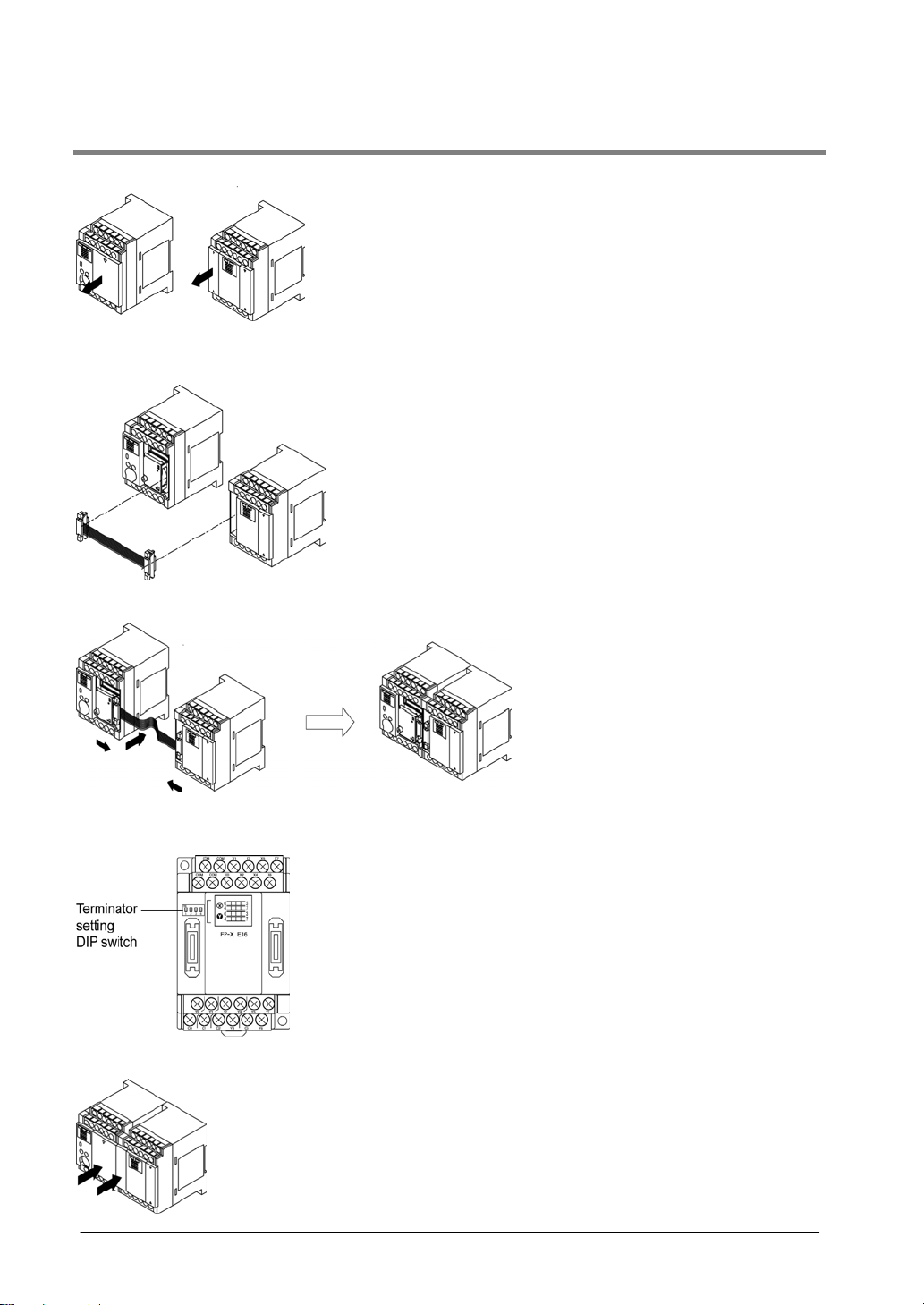
5.2.1 Expansion Method of FP-X Expansion Unit
CTi Automation - Phone: 800.894.0412 - Fax: 208.368.0415 - Web: www.ctiautomation.net - Email: info@ctiautomation.net
1. Remove the expansion cover.
2. Fit the expansion connector cable into the expansion connector part of the control unit and the
one (left side) of the expansion I/O unit.
3. Push the expansion connector cable inside to touch the units each other.
4. Set the terminator setting switch. All the switches of the expansion unit installed at the last
position should be on.
5. Install the expansion cover.
5-6
Page 77

CTi Automation - Phone: 800.894.0412 - Fax: 208.368.0415 - Web: www.ctiautomation.net - Email: info@ctiautomation.net
5.2.2 How to Connect with FP-X Expansion FP0 Adapter
1. Remove the expansion cover.
There is no expansion cover for the expansion FP0 adapter.
2. Fit the expansion connector cable into the expansion connector part.
3. Push the expansion connector cable inside.
4. Install the expansion cover.
Note:
Although there is no terminator setting switch for the expansion FP0 adapter, the terminator setting has
been done within the expansion FP0 adapter. Turn off the terminator setting switches of the other
expansion units.
5-7
Page 78

5.3 Expansion Method of FP0 Expansion Unit
CTi Automation - Phone: 800.894.0412 - Fax: 208.368.0415 - Web: www.ctiautomation.net - Email: info@ctiautomation.net
The FP0 expansion unit (expansion unit, intelligent unit) is expected b y connecting to the right side of the
FP-X expansion FP0 adapter.
Unit expansion is done using the right-side connector for FP0 expansion and expansion hook on the side
of the unit.
1. Raise the expansion hooks on the top and bottom sides of the un it with a screwdriver.
2. Align the pins and holes in the four corners of the control unit and expansion unit, and insert
the pins into the holes so that there is no gap between the units.
3. Press down the expansion hooks raised in step 1 to secure the unit.
5-8
Page 79

CTi Automation - Phone: 800.894.0412 - Fax: 208.368.0415 - Web: www.ctiautomation.net - Email: info@ctiautomation.net
5.4 How to Install Add-on Cassette
The add-on cassette is fitted with the control unit using the provided screws.
Note:
The add-on cassette must be secured with the control unit using the screws in the actual use for
preventing the affect of vibrations.
The backup battery (option) should be before installing the add-on cassette.
The installation must be carried out when the power supply is off. If the power supply is on, it may cause
faults.
Recommended screw
Recommended screw Size and other conditions Quantity
Tapping screw
Material: SW pan head (+) P-tight 2.6-16
galvanization, trivalent chromate (black)
5.4.1 Installing Communicaion Cassette
Note:
The communication cassette can be installed only in the cassette mounting part 1 of the control
unit.
Installation on the control unit
Connect the connector on the back of the communication cassete and the connector of the cassette
mounting part of the control unit, and secure the two positions, bottom left and top right, with the screws.
It is no problem if the ribs remain. (AFPX-COM5 has no rib.)
The screw’s tightening torque should be 0.3 to 0.5 N・m. Screw securely.
2 pcs/1 cassette
Installation on the application cassette
Remove the cover of the application cassette that was secured previously.
Connect the connector on the back of the communication cassete and the connector at the front of the
application cassette, and secure the two positions, top left and bottom right of the communication
cassette which the ribs were cut, with the screws. (AFPX-COM5 has no rib. Install it after the wiring of
the application cassette.)
The screw’s tightening torque should be 0.3 to 0.5 N・m. Screw securely.
5-9
Page 80

5.4.2 Installing Application Cassette
CTi Automation - Phone: 800.894.0412 - Fax: 208.368.0415 - Web: www.ctiautomation.net - Email: info@ctiautomation.net
Note:
The application cassette can be installed only in the cassette mounting part 1 and 2 of the control
unit.
Installation on the control unit
Connect the connector on the back of the application cassete and the connector of the cassette
mounting part of the control unit, and secure the two positions, bottom left and top right, with the screws.
The screw’s tightening torque should be 0.3 to 0.5 N・m. Screw securely.
5.4.3 Precautions on Installation
Do not touch the back side of the add-on cassette and the connector.
The parts such as IC, etc. may be damaged by static electricity.
5.4.4 State When Add-on Cassette is Installed
5-10
Page 81

CTi Automation - Phone: 800.894.0412 - Fax: 208.368.0415 - Web: www.ctiautomation.net - Email: info@ctiautomation.net
5.5 Power Supply
5.5.1 Power Supply for Control Unit
Wiring of power supply
Confirm that the power supply voltage is within the allowable range of the power supply.
Rated input voltage
100 to 240 V AC 85 to 264 V AC 50/60 Hz 47 to 63 Hz
Note:
Using the power supply of the outlying voltage and frequency, or using inappropriate wires ma y cause
the fault of the power supply of the PLC.
Reference: <5.7 Wiring of Terminal Block>
Allowable voltage
amplitude range
Rated frequnecy
Allowable frequency
range
Isolation of power supply systems
Isolate the wiring systems to the FP-X, output devices and mechanical power apparatus.
5-11
Page 82

Note: Power supply of the FP-X expansion units
CTi Automation - Phone: 800.894.0412 - Fax: 208.368.0415 - Web: www.ctiautomation.net - Email: info@ctiautomation.net
Be sure to supply power to the FP-X expansion units and the control unit from the same power supply,
and turn the power on and off simultaneously for both.
To avoid the influence of noises
Use the power supply causing less noise. The inherent noise resistanc e is sufficient for the noise
superimposed on the power wires, however, the noise can be attenuated further by using the isolation
transformer.
Also, twist the power supply cables to minimize adverse effects from noise.
Grounding
Ground the instrument to increase noise suppression.
Exclusive grounding
• For gounding purposes, use wiring with a minimum of 2 mm
resistance of less than 100Ω.
• The point of grounding should be as close to the PLC unit as possible. The ground wire should be as
short as possible.
• If two devices share a single ground point, it may produce an adverse effect. Always use an exclusive
ground for each device.
2
. The grounding connection should have a
5-12
Page 83

CTi Automation - Phone: 800.894.0412 - Fax: 208.368.0415 - Web: www.ctiautomation.net - Email: info@ctiautomation.net
5.5.2 Power Supply for Expansion FP0 Adapter
Power supply wiring for the unit
Use the power supply cable (Part No.:AFP0581) that comes with the unit to connect the power supply.
- Brown: 24V DC
- Blue: 0V
- Green: Function earth (FE)
Power supply wire
To minimize adverse effects from noise, twist the brown and blue wires of the power supply cable.
Power supply from the servicing power supply for the input of the FP-X control unit
• To protect the system against erroneous voltage from the power supply line, use an insulated power
supply with an internal protective circuit (electric cable that reinforced insulation or double insulation
has been made).
• The regulator on the unit is a non-insulated type.
• To turn the power supplies on simultaneously, supply the power for the expansion FP0 adapter from
the servicing power supply for the input of the FP-X control unit.
5-13
Page 84

Measures regarding power supply sequence (start up sequence)
CTi Automation - Phone: 800.894.0412 - Fax: 208.368.0415 - Web: www.ctiautomation.net - Email: info@ctiautomation.net
• To ensure and ease the power supply sequence of the expansion FP0 adapter, supply the power for
the expansion FP0 adapter from the servicing power supply for the input of the FP-X control unit.
• The power supply sequence should be set up so that power to the FP0 expansion unit is turned on
before the FP-X system power supply.
• The power supply sequence should be set up so that power to the FP-X system and FP0 expansion
unit is turned off before the input/output power supplies. If the input/output power supplies are turned
off before the power to the expansion FP0 adapter, the control unit will detect the input fluctuations and
may begin an unscheduled operation.
When turning on:
Power supply for FP0 → Power supply for FP-X, Expansion FP0 adapter → Power supplies for I/O
devices
When turning off:
Power supply for FP-X, Expansion FP0 adapter → Power supply for FP0 → Power supplies for I/O
devices
Grounding
- In situations of excess noise
Under normal conditions, the inherent noise resistance is sufficient. However, in situations of excess
noise, ground the instrument to increase noise suppression.
- Exclusive grounding
• The grounding connection should have a resistance of less than 100Ω.
• The point of grounding should be as close to the PLC unit as possible. The ground wire should be as
short as possible.
• If two devices share a single ground point, it may produce an adverse effect. Always use an exclusive
ground for each device.
Note:
Depending on the surroundings in which the equipment is used, grounding may cause problems.
[Example]
Since the power supply line of the expansion FP0 adapter po wer supply connector is connected to the
function earth through a varistor, if there is an irregular potential between the power supply line and earth,
the varistor may be shorted.
5-14
Page 85

CTi Automation - Phone: 800.894.0412 - Fax: 208.368.0415 - Web: www.ctiautomation.net - Email: info@ctiautomation.net
5.6 Wiring of Input and Output
Do not apply the voltage that exceeds the rated input voltage to the input terminal.
5.6.1 Input Wiring
Connection of photoelectric sensor and proximity sensor
Relay output type
Voltage output type
NPN open collector output type
Two-wire output type
Precaution when using LED-equipped lead switch
Precaution when using two-wire type sensor
When a LED is connected in series to an input
contact such as LED-equipped lead switch, make
sure that the on voltage applied to the PLC input
terminal is greater than 21.6V DC. In particular,
take care when connecting a number of switches
in series.
If the input of PLC does not turn off because of
leakage current from the two-wire type sensor
“photoelectric sensor or proximity sensor”, the use
of a bleeder resistor is recommended, as shown
below.
The formula is based on an input impedance of
5.6kΩ. The input impedance varies depending on
the input terminal number.
5-15
Page 86

Precaution when using LED-equipped limit switch
CTi Automation - Phone: 800.894.0412 - Fax: 208.368.0415 - Web: www.ctiautomation.net - Email: info@ctiautomation.net
If the input of PLC does not turn off because of
the leakage current from the LED-equipped limit
switch, the use of a bleeder resistor is
recommended, as shown below.
Servicing power supply for input
Use it for input and the expansion FP0 adapter. (Use an external power supply for the FP0 expansion
unit.)
When it is used for another device, confirm the consumption current of the device side before it is
connected. If excess current is being supplied for a long time, the power supply may be damaged.
5.6.2 Output Wiring
Do not connect a load that exceeds the maximum swiching ability to the output terminal.
Protective circuit for inductive loads
• With an inductive load, a protective circuit should be installed in parallel with the load.
• When switching DC inductive loads with relay output type, be sure to connect a diod across the ends of
the load.
When using an AC inductive load
5-16
Page 87

CTi Automation - Phone: 800.894.0412 - Fax: 208.368.0415 - Web: www.ctiautomation.net - Email: info@ctiautomation.net
When using a DC inductive load
Precautions when using capacitive loads
When connecting loads with large in-rush currents, to minimize their effect, connect a protection circuit
as shown below.
5.6.3 Precautions Regarding Input and Output Wirings
Isolate input/output/power lines
• Be sure to select the thickness (dia.) of the input and output wires while taking into consideration the
required current capacity.
• Arrange the wiring so that the input and output wiring are separated, and these wirings are separ ated
from the power wiring, as much as possible. Do not route them through the same duct or wrap them up
together.
• Separate the input/output wires from the power and high voltage wires by at least 100mm.
• Wirings other than the above specifications or incorrect wirings may cause the fault or malfunction.
Others
• Wiring should be carried out after the power supply to the PLC was turned off.
• Also turn of the power supply when the control unit, expansion units and various cassettes are
connected. If they are connected during the power supply is on, it may cause the fault or malfunction.
5-17
Page 88

5.7 Wiring of Terminal Block
CTi Automation - Phone: 800.894.0412 - Fax: 208.368.0415 - Web: www.ctiautomation.net - Email: info@ctiautomation.net
Supplied terminal block/Suitable wires
M3 terminal screws are used for the terminal. The following suitable solderless terminals are
recommended for the wiring to the terminals
Suitable solderless terminals
Manufacturer Shape Part No. Suitable wires (mm2)
JST Mfg. Co., Ltd.
Suitable wires
Suitable wires Tightening torque
AWG22 to 14 0.3 to 2.0 mm2
The tightening torque should be 0.5 to 0.6 N・m
Connection to the terminal block
When using the round type terminal, remove the terminal cover.
Round type 1.25-MS3
Fork type 1.25-B3A
Round type 2-MS3
Fork type 2-N3A
0.25 to 1.65
1.04 to 2.63
Note:
Install the terminal block cover as it was after wiring to prevent electric shock.
5-18
Page 89

CTi Automation - Phone: 800.894.0412 - Fax: 208.368.0415 - Web: www.ctiautomation.net - Email: info@ctiautomation.net
How to remove the terminal block
The terminal blocks used for C30/C60/E30 can be removed for fitting the screws.
(The terminal block for C14/E16 cannot be removed.)
The tightening torque should be 0.25 to 0.35 N•m.
5-19
Page 90

5.8 Wiring of Add-on Cassette Terminal Block
CTi Automation - Phone: 800.894.0412 - Fax: 208.368.0415 - Web: www.ctiautomation.net - Email: info@ctiautomation.net
A screw-down connection type for terminal block is used for the add-on cassette. The suitable wires are
given below.
Suitable wires (twisted)
Size Nominal cross-sectional area
AWG #28 to 16 0.08 to 1.00 mm2
Note: When using the communication cassette, <5.8.1 Transmission Cables>
Pole terminal with a compatible insulation sleeve
If a pole terminal is being used, the following models manufactured by Phoenix Contact Co. should be
used.
Manufacturer
Phoenix
Contact Co.
Pressure welding tool for pole terminals
Manufacturer Part No. Product No.
Phoenix Contact Co. CRIMPFOX UD6 1204436
For tightening the terminal block
When tightening the terminals of the terminal block, use a screwdriver (Phoenix contact Co., Product No.
1205037) with a blade size of 0.4 × 2.5 (Part No. SZS 0,4×2,5).
The tightening torque should be 0.22 to 0.25 N・m.
Cross-sectional
area (mm2)
0.25 AWG #24 AI 0, 25-6 BU -
0.34 AWG #22 - A 0, 34-6
0.50 AWG #20 - A 0, 5-6
0.75 AWG #18 - -
1.00 AWG #18 - -
0.5×2 AWG #20 (for 2 pcs) - -
Size
With
insulating sleeve
Part No.
Without
insulating sleeve
5-20
Page 91

CTi Automation - Phone: 800.894.0412 - Fax: 208.368.0415 - Web: www.ctiautomation.net - Email: info@ctiautomation.net
Wiring method
(1) Remove a portion of the wire’s insulation.
(2) Insert the wire into the terminal block until it contacts the back of the block socket, and then
tighten the screw clockwise to fix the wire in place. (Tightening torque: 0.22 to 0.25 N·m)
Precautions on wiring
• When removing the wire’s insulation, be careful not to scratch the core wire.
• Do not twist the wires to connect them.
• Do not solder the wires to connect them. The solder may break due to vibration.
• After wiring, make sure stress is not applied to the wire.
• In the terminal block socket construction, if the wire closes upon counter-clockwise rotation, the
connection is faulty. Disconnect the wire, check the terminal hole, and then re-connect the wire.
• If two wires are connected to the plus terminal and minus terminal of the RS485, use the wires of the
same cross-sectional area which is 0.5 mm
2
.
5-21
Page 92

5.8.1 Transmission Cables
CTi Automation - Phone: 800.894.0412 - Fax: 208.368.0415 - Web: www.ctiautomation.net - Email: info@ctiautomation.net
Please use the following cables for systems using the communication cassette.
Appropriate electrical cables (twisted cables)
Conductor Insulator
Type
Shielded
twisted
pair
VCTF
Shielded
multicore
cable
Cross-sectional
view
Size
0.5 mm2
(AWG20)
0.5 mm2
(AWG20)
0.3 mm2
(AWG22)
or greater
Resist-
ance
(at 20°C)
Max.
33.4
Ω/km
Max.
37.8
Ω/km
Max.
58.8
Ω/km
Material
Polye-
thylene
Polychlo-
rinated
biphenyl
Vinyl
chloride
Thick-
ness
Max.
0.5 mm
Max.
0.6 mm
Max.
0.3 mm
Cable
diam.
Approx.
7.8 mm
Approx.
6.2 mm
Approx.
6.6 mm
Sample
appropriate
cable
Belden 9207
Hitachi Cable,
Ltd. KPEV-
S0.5 mm
mm
Onamba Co.,
Ltd. ONB-D6 x
2
1P
VCTF-0.5
2
x 2C(JIS)
2
0.3 mm
x
Note:
• Use shielded twisted pair cables.
• Use only one type of transmission cable. Do not mix more than 1 type.
• Twisted pair cables are recommended in noisy environments.
• When using shielded cable with crossover wiring for the RS485 transmission line, grounded one end.
• If two wires are connected to the plus terminal and minus terminal of the RS485, use the wires of the
same cross-sectional area which is 0.5 mm
2
.
5-22
Page 93

CTi Automation - Phone: 800.894.0412 - Fax: 208.368.0415 - Web: www.ctiautomation.net - Email: info@ctiautomation.net
5.9 Installation and Setting of Backup Battery
Installing a backup battery in the FP-X makes it possible to access realtime clock function for use (when
the master memory cassette AFPX-MRTC is installed), in addition to backing up data registers and other
data.
Battery (Option)
Name Part No.
Backup battery for FP-X AFPX-BATT 1 pc Max. 2 pcs Max. 3 pcs
The battery can be installed in the cassette mounting parts 1, 2 and the expansion conn ector part.
Quantity that can be installed
C14 C30 C60
5-23
Page 94

5.9.1 Installation of Backup Battery
CTi Automation - Phone: 800.894.0412 - Fax: 208.368.0415 - Web: www.ctiautomation.net - Email: info@ctiautomation.net
The procedure shown below is the one after the expan sion cover was removed.
1. Remove the battery cover.
2. Place the battery and connect the connector to the unit.
Note) When replacing the battery, turn off the power after supplying the power more than 5 min., and
then fit the new battery within 2 minutes of removing the old one.
3. Fit the battery cover.
Overhead view
5-24
Page 95

CTi Automation - Phone: 800.894.0412 - Fax: 208.368.0415 - Web: www.ctiautomation.net - Email: info@ctiautomation.net
5.9.2 System Register Setting
Setting of the battery error alarm
In the system register default settings, “No. 4 Alarm Battery Error” is set to “Off”. When using the battery,
set system register No. 4 of the control unit so that the battery error alarm is turned on.
Setting procedure using FPWIN GR
1. Select “PLC Configuration” on the “Option” menu, and click on “Action on Error” tab.
2. Turn on “No. 4 Alarm Battery Error” check box.
PLC Configuration setting dialog box
Specifying the hold area
In order to use backup functions such as data registers, settings must be entered for system registers
Nos. 6 to 14.
For hold area setting using FPWIN GR, select “PLC Configuration” on the “Option” menu, and click on
“Hold/Non-hold1” and “Hold/Non-hold 2”.
Note:
• The setting of the system registers Nos. 6 to 14 is effective only when the backup battery is mounted.
• Without the battery, use at the default settings. If changing the settings, the “Hold/Non-hold” operation
becomes unstable.
• Without the settings, the data may be lost as the result of the battery shutoff.
5.9.3 Time for Replacement of Backup Battery
If system register “No.4 Alarm Battery Error” is set to “ON”, it informs about the proper time to
replace the backup battery.
1. Special internal relays R9005 and R9006 will go on if the battery voltage drops.
2. ERROR/ALARM LED will flash.
The battery remains effective for about a week
is not detected immediately. The battery should be replaced as soon as possible.
Note) When replacing the battery, turn off the power after supplying the power more than 5 min.,
and then fit the new battery within 2 minutes of removing the old one.
after the alarm is issued, but in some cases the problem
Key Point: When the backup battery has not been installed
R9005 and R9006 are always on regardless of the setting of the system register No. 4.
5-25
Page 96

5.9.4 Lifetime of Backup Battery
CTi Automation - Phone: 800.894.0412 - Fax: 208.368.0415 - Web: www.ctiautomation.net - Email: info@ctiautomation.net
The life of the backup battery will eventually expire and therefore it is important to replace it with
a new battery periodically. Refer to the table below for a guide as to when to replace the battery.
1 pc for C14, max. 2 pcs for C30 and max. 3 pcs for C60 can be connected.
Battery lifetime: when the master memory cassette (AFPX-MRTC) is installed
Descriptions
Control unit
C14 1 2.1 years or more 3 years 10 years (25 °C)
C30
C60
Note1) The battery lifetime is the value when no power at all is supplied.
Note2) Note that the lifetime in actual use may be shorter than the typical lifetime depending on the use
conditions.
Quantity used Battery lifetime
1 1.8 years or more 3 years 10 years (25 °C)
2 3.7 years or more 5 years 20 years (25 °C)
1 1.8 years or more 3 years 10 years (25 °C)
2 3.7 years or more 5 years 20 years (25 °C)
3 5.6 years or more 8 years 20 years (25 °C)
Battery lifetime: when the master memory cassette (AFPX-MRTC) is not installed
Descriptions
Control unit
C14 1 3.3 years or more 5 years 20 years (25 °C)
C30
C60
Note1) The battery lifetime is the value when no power at all is supplied.
Note2) Note that the lifetime in actual use may be shorter than the typical lifetime depending on the use
conditions.
Quantity used Battery lifetime
1 2.7 years or more 4 years 20 years (25 °C)
2 5.4 years or more 8 years 20 years (25 °C)
1 2.7 years or more 4 years 20 years (25 °C)
2 5.4 years or more 8 years 20 years (25 °C)
3 8.1 years or more 12 years 20 years (25 °C)
Suggested
replacement interval
Suggested
replacement interval
Typical lifetime in
actual use
Typical lifetime in
actual use
5-26
Page 97

CTi Automation - Phone: 800.894.0412 - Fax: 208.368.0415 - Web: www.ctiautomation.net - Email: info@ctiautomation.net
5.10 Safety Measures
5.10.1 Safety Measures
Precautions regarding system design
In certain applications, malfunction may occur for the following reasons:
• Power on timing differences between the PLC system and input/output or mechanical power apparatus.
• Response time lag when a momentary power drop occurs.
• Abnormality in the PLC unit, external power supply, or other devices.
In order to prevent a malfunction resulting in system shutdown choose the adequate safety measures
listed in the following:
Interlock circuit
When a motor clockwise/counter-clockwise operation is controlled, provide an interlock circuit externally.
Emergency stop circuit
Provide an emergency stop circuit to the PLC externally to turn off the power supply of the output device.
Start up sequence
The PLC should be operated after all of the outside devices are energized. To keep this sequence, the
following measures are recommended:
• Turn on the PLC with the mode selector set to the PROG. mode, and then switch to the RUN mode.
• Program the PLC so as to disregard the inputs and outputs until the outside devices are energized.
Note) In case of stopping the operation of the PLC also, have the input/output devices turned off after the
PLC has stopped operating.
Grounding
When installing the PLC next to devices that generate high voltages from switching, such as inverters,
do not ground them together. Use an exclusive ground for each device.
The terminal block cover must be used for preventing electric shock.
5.10.2 Momentary Power Failures
Operation of momentary power failures
If the duration of the power failure is less than 10 ms, the FP-X continues to operate. If the power is off
for 10 ms or longer, operation changes depending on the combination of units, the power supply voltage,
and other factors. (In some cases, operation may be the same as that for a power supply reset.)
Although the duration of the power failure for the expansion FP0 adapter is 10 ms, judge the permissibl e
time as a system after confirming the permissible duration of the power failures for the DC power supply
that supplies power to the expansion FP0 apapter. (Supply the power to it from the servicing power
supply for the input of the FP-X control unit.) When the expansion unit that has a power supply built-in
(E30 expansion FP0 adapter), depending on the duration of the momentar y power failure, only one unit
may be without electricity momentarily and the I/O verify error may occur. In that case, turn off the power
supply and then turn on again.
5.10.3 Protection of Output Sections
Protection of output
If current exceeding the rated control capacity is being supplied in the form of a motor lock current or a
coil shorting in an electromagnetic device, a protective element such as a fuse should be attached
externally.
5-27
Page 98

CTi Automation - Phone: 800.894.0412 - Fax: 208.368.0415 - Web: www.ctiautomation.net - Email: info@ctiautomation.net
5-28
Page 99

CTi Automation - Phone: 800.894.0412 - Fax: 208.368.0415 - Web: www.ctiautomation.net - Email: info@ctiautomation.net
Chapter 6
Tool Port and USB Port
Page 100

6.1 Tool Port and USB Port
CTi Automation - Phone: 800.894.0412 - Fax: 208.368.0415 - Web: www.ctiautomation.net - Email: info@ctiautomation.net
Tool port (RS232C)
This port is used to connect a programming tool.
A commercial mini-DIN 5-pin connector is used for the Tool port on the control unit.
Pin No. Signal name Abbreviation Signal direction
1 Signal Ground SG −
2 Send Data SD Unit → External device
3 Receive Data RD Unit ← External device
4 (Not used) − −
The followings are the default settings set when the unit is shipped from the factory.
- Baud rate …….. 9600 bps
- Character bit …. 8 bit
- Parity check ….. Odd parity
- Stop bit length .. 1 bit
5 +5V +5V Unit → External device
USB connector
This is a connector to connect the programming tool.
The connector is the commercial B type.
Commercial USB cables (AB type) can be used.
6-2
 Loading...