

Panasonic Fax KX-FT21LA Schematic
ORDER NO. KM79905276C3
KX-FT21LA
INTRODUCTION
PERSONAL F ACSIMILE
KX-FT21LA
(for Latin America)
WARNING
This service information is designed for experienced repair technicians only and is not designed for use by the general public.
It does not contain warnings or cautions to advise non-technical individuals of potential dangers in attempting to service a product.
Products powered by electricity should be serviced or repaired only by experienced professional technicians.
Any attempt to service or repair the product or products dealt with in this service information by anyone else could result in serious
injury or death.
C
1999 Kyushu Matsushita Electric Co., Ltd.
All rights reserved. Unauthorized copying and distribution is a violation of law.
- 1 -

KX-FT21LA
When you note the serial number, write down all 11 digits. The serial number may be found on the bottom of the unit.
INTRODUCTION
TABLE OF CONTENTS
Page
Safety Precautions ............................................................................................................................. 5
Insulation Resistance Test .................................................................................................................. 5
For Service Technicians...................................................................................................................... 5
Battery Caution .................................................................................................................................. 6
AC Cautio n......................................................................................................................................... 6
Personal Safety Precautions............................................................................................................... 7
Specifications ..................................................................................................................................... 8
Optional Accessories.......................................................................................................................... 8
CCITT No.1 Test Chart ...................................................................................................................... 9
Location of Controls ................................................................................................................... 10~11
Features ........................................................................................................................................... 12
Connections ..................................................................................................................................... 13
Installation .................................................................................................................................. 14~16
Document stacker ............................................................................................................................ 14
Document you ca n Se nd .................................................................................................................. 16
Maintenance Items and Component Locations........................................................................... 17~20
TROUBLESHOOTING GUIDE
Troubleshooting Summary................................................................................................................ 22
User Recoverable Errors .................................................................................................................. 23
Document jam .................................................................................................................................. 24
Troubleshooting Details .............................................................................................................. 25~82
Programming and Lists............................................................................................................... 83~87
Test Functions ............................................................................................................................ 88~89
Journal 3 .................................................................................................................................... 90~91
ADJUSTMENTS
Adjusting the Feeder Pressure ......................................................................................................... 93
DISASSEMBL Y INSTRUCTIONS
Diassembly Instructions ........................................................................................................... 95~105
How to Replace the Flat Package IC ...................................................................................... 106~107
- 2 -

CIRCUIT OPERA TIONS
Connection Diagram....................................................................................................................... 109
General Block Diagram .......................................................................................................... 110~111
Control Section....................................................................................................................... 112~120
Facsimile Section ................................................................................................................... 120~132
MODEM Section .................................................................................................................... 133~140
NCU Section .......................................................................................................................... 141~142
ITS and Monitor Section ................................................................................................................. 143
EXT. TEL................................................................................................................................. 144~145
Operation Panel...................................................................................................................... 146~147
Power Supply Switching Board Section ................................................................................. 148~151
KX-FT21LA
INTRODUCTION
PRINTED CIRCUIT BOARD (DIGIT AL BOARD) ............................................................................. 153~156
SCHEMATIC DIAGRAM (DIGITAL CIRCUIT) ......................................................................................... 157
SCHEMATIC DIAGRAM (ANALOG CIRCUIT) ........................................................................................ 158
PRINTED CIRCUIT BOARD (ANALOG BOARD)............................................................................ 159~160
PRINTED CIRCUIT BOARD (SWITCHING POWER SUPPLY) .............................................................. 161
SCHEMATIC DIAGRAM (SWITCHING POWER SUPPLY) .................................................................... 162
PRINTED CIRCUIT BOARD (OPERATION BOARD) ............................................................................. 163
SCHEMATIC DIAGRAM (OPERATION CIRCUIT).................................................................................. 164
TERMINAL GUIDE OF THE IC'S TRANSISTORS AND DIODES ........................................................... 165
FIXTURES AND TOOLS ........................................................................................................................ 166
CABINET, MECHANICAL AND ELECTRICAL PARTS LOCATION ................................................ 167~171
ACCESSORIES AND PACKING MATERIALS ........................................................................................ 172
REPLACEMENT PARTS LIST ........................................................................................................ 173~179
- 3 -

KX-FT21LA
INTRODUCTION
Page
Safety Precautions ................................................................................... 5
Insulation Resistance Test........................................................................5
For Service Technicians ........................................................................... 5
Battery Caution ........................................................................................ 6
AC Cautio n............................................................................................... 6
Personal Safety Precautions .................................................................... 7
Specifications........................................................................................... 8
Optional Accessories ............................................................................... 8
CCITT No.1 Test Chart ............................................................................ 9
Location of Controls ......................................................................... 10~11
Features................................................................................................. 12
Connections ........................................................................................... 13
Installation........................................................................................ 14~16
Document stacker .................................................................................. 14
Documents you can send....................................................................... 16
Maintenance Items and Component Locations ................................ 17~20
- 4 -
KX-FT21LA
SAFETY PRECAUTIONS
1. Before servicing, unplug the AC power cord to prevent an electric shock.
2. When replacing parts, use only the manufacturer’s recommended components.
3. Check the condition of the power cord. Replace if wear or damage is evident.
4. After servicing, be sure to restore the lead dress, insulation barriers, insulation papers, shields, etc.
5. Before returning the serviced equipment to the customer, be sure to perform the following insulation resistance test to
prevent the customer from being exposed to shock hazards.
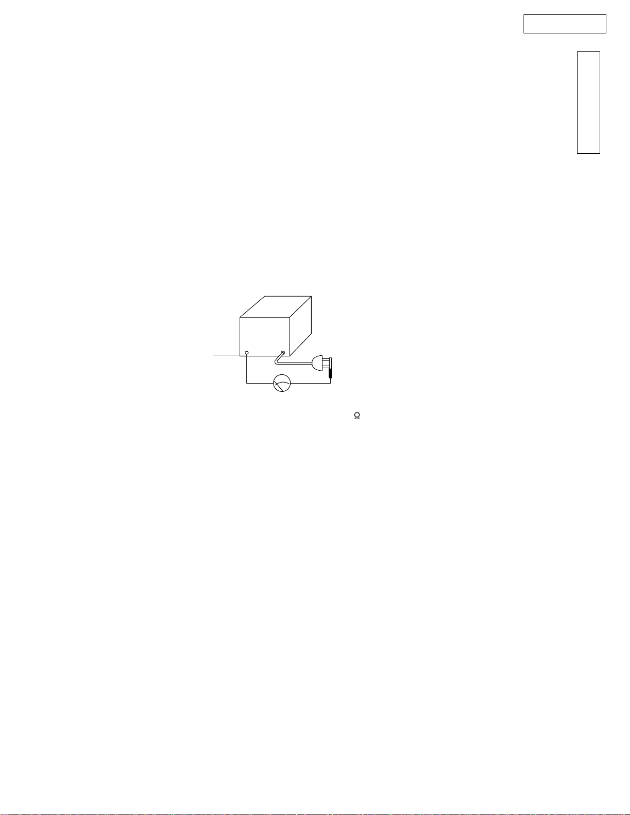
INSULA TION RESISTANCE TEST
1. Unplug the power cord and short the two prongs of the plug with a jumper wire.
2. Turn on the power switch.
3. Measure the resistance value with an ohmmeter between the jumpered AC plug and each exposed metal cabinet part
(screwheads, control shafts, bottom frame, etc.).
Note: Some exposed parts may be isolated from the chassis by design. These will read infinity.
4. If the measurement is outside the specified limits, there is a possibility of a shock hazard.
The equipment should be repaired and rechecked before it is returned to the customer.
INTRODUCTION
Exposed
metal
part
Ohmmeter
Resistance = more than 1M
(at DC 500 V)
FOR SERVICE TECHNICIANS
ICs and LSIs are vulnerable to static electricity.
When repairing, the following precautions will help prevent recurring malfunctions.
1) Cover the plastic part’s boxes with aluminum foil.
2) Ground the soldering irons.
3) Use a conductive mat on the worktable.
4) Do not touch the IC or LSI pins with bare fingers.
- 5 -
KX-FT21LA
BA TTER Y CAUTION
CAUTION
Danger of explosion if battery is incorrectly replaced.
Replace only with the same or equivalent type recommended
by the manufacture. Dispose of used batteries according
to the manufacturer's instructions.
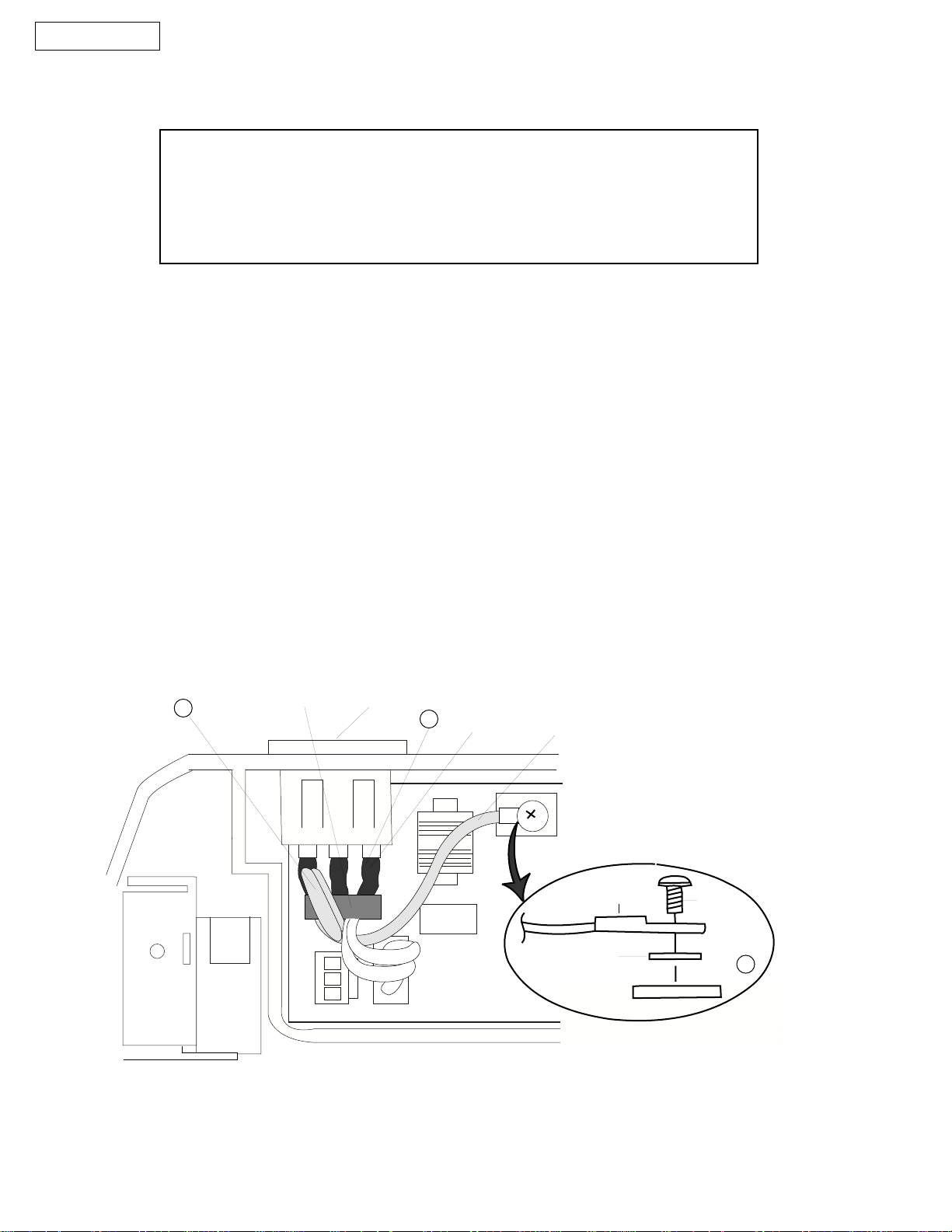
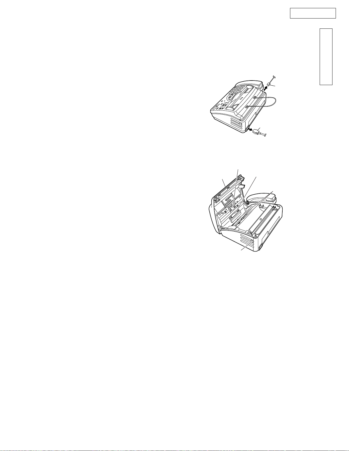
AC CAUTION
For safety, before closing the lower cabinet, please make sure of the following precautions.
1.The earth lead is fixed with the screw.
2.The AC connector is connected properly.
3.Wrap the AC lead around the core 2 times.
(BOTTOM VIEW)
Earth Lead
3
(Ferrite Core)
AC Inlet
2
AC Lead
Earth Lead
Earth
Lead
Screw
- 6 -
Washer
1

KX-FT21LA
PERSONAL SAFETY PRECAUTIONS
1. MOVING SECTIONS OF THE UNIT
Be careful not to let your hair, clothes, fingers, accessories, etc., become caught in any moving sections of the unit.
The moving sections of the unit are the rollers and a gear. There is a separation roller and a document feed roller which
are rotated by the document feed motor. A gear rotates the two rollers. Be careful not to touch them with your hands,
especially when the unit is operating.
Sub roller
Rubber flap
White plate
Document feeder rollers
Gear
Glass
INTRODUCTION
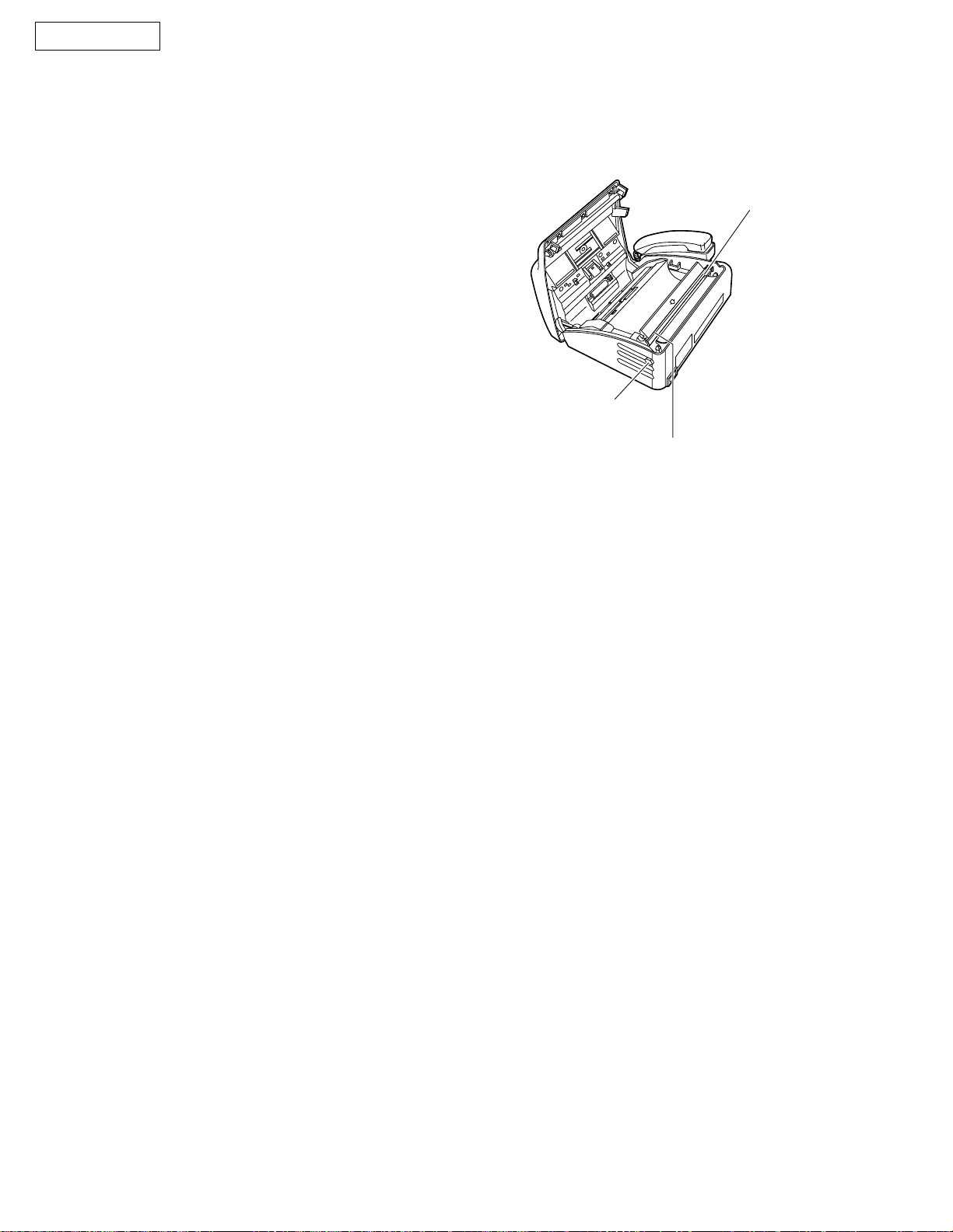
2. LIVE ELECTRICAL SECTIONS
All the electrical sections of the unit supplied with AC power by the AC power cord are live.
Never disassemble the unit for service with the AC power supply plugged in.
AC voltage is supplied to the primary side of the power supply unit.
Therefore, always unplug the AC power cord before disassembling for service.
Be careful of "High Voltage" in this area.
(Bottom view)
- 7 -

KX-FT21LA
General
Desktop type
LCD (Liquid Crystal Display) readout
Help function
Copier function
Facsimile
Space Saving Compact Design
Resolution: standard/fine/super fine/halftone
Copier Function
Automatic Document Feeder (10 Sheets)
Help Printout
Easy-to-view LCD (15 Characters)
FEA TURES
Integrated telephone system
Electric Volume Control
On-hook dialing
Redialing function
Temporary tone dialing
Electric telephone directory
- 8 -

KX-FT21LA
SPECIFICATIONS
Applicable Lines: Public Switched Telephone Network
Document Size: Max. 216 mm (81/2”) in width
Max. 600 mm (235/8”) in length
Effective Scanning Width: 208mm (83/16”)
Recording Paper Size: 216 mm max. 30 m (81/2”•~98’) roll
3
Effective Printing Width: 208 mm (8
Transmission Time*: Approx. 15 s/page (Original mode)**
Approx. 30 s/page (G3 Normal mode)
Scanning Density: Horizontal: 8 pels/mm (203 pels/inch)
Vertical: 3.85 lines/mm (98 lines/inch)—STANDARD mode
Halftone Level: 64-level
Scanner Type: Contact Image Sensor (CIS)
Printer Type: Thermal Printing
Data Compression System:
Modem Speed: 9,600 / 7,200 / 4,800 / 2,400 bps; Automatic Fallback
Operating Environment: 5ßC - 35ßC (41ßF - 95ßF), 45 % - 85 % RH (Relative Humidity)
Dimensions (H• ~W•~D): 122 mm•~338 mm•~240 mm (4
Mass (Weight): Approx. 2.5 kg (5.5 lb.)
Power Consumption: Standby: Approx. 5.5 W
Power Supply: 220 - 240 V AC, 50/60 Hz
Modified Huffman (MH), Modified READ (MR)
Transmission: Approx. 17 W
Reception: Approx. 30 W (When receiving the CCITT No. 1 Test Chart)
Copy: Approx. 30 W (When copying the CCITT No. 1 Test Chart)
Maximum: Approx. 120 W (When copying a 100 % black document)
/16”)
7.7 lines/mm (196 lines/inch)—FINE/HALF TONE mode
15.4 lines/mm (392 lines/inch)—SUPER FINE mode
13
/16” •~135/16”•~97/16”)
INTRODUCTION
**Transmission speed depends upon the contents of the pages, resolution,
telephone line conditions and capability of the other party’s machine.
** The 15 second speed is based upon the CCITT No. 1 Test Chart.
Note:
Any details given in these instructions are subject to change without notice.
The pictures and illustrations in these instructions may vary slightly from the actual product.
OPTIONAL ACCESSORIES
Parts No.
KX-A106
Description
Standard thermal recording paper
216 mm • ~ 30 m (8
Comment
1
/2"• ~98') roll,with 25 mm (1") core
- 9 -
KX-FT21LA
CCITT NO. 1 TEST CHART (Actual size)
- 10 -
KX-FT21LA
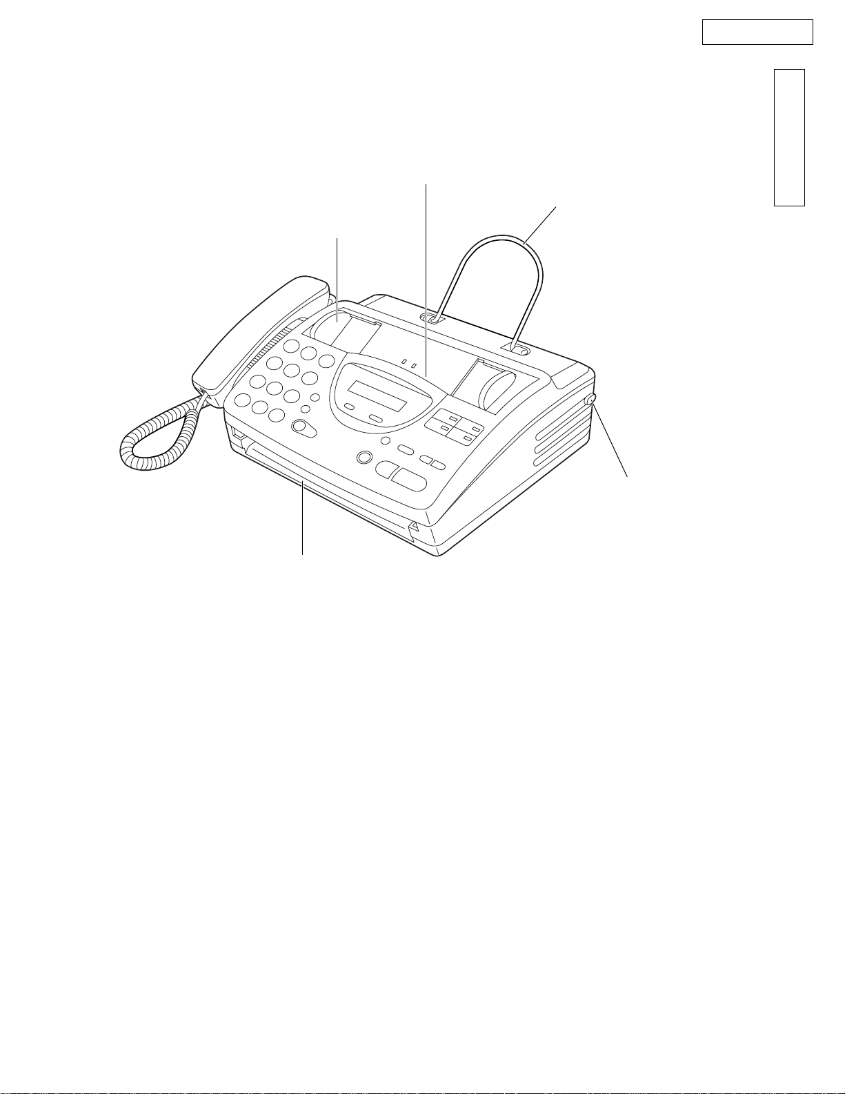
1.OVERVIEW
LOCATION OF CONTROLS
Document entrance
Document guide(s)
INTRODUCTION
Document stacker
Document exit
Cover open button
- 11 -
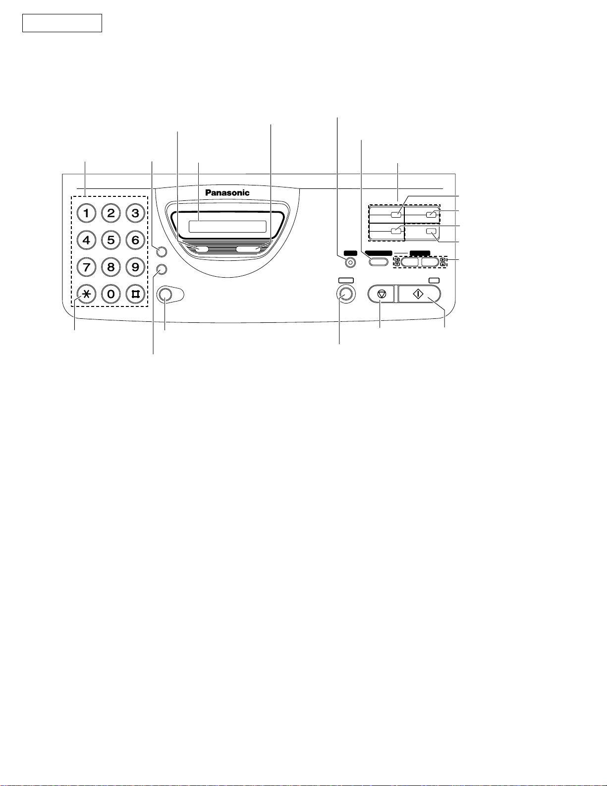
KX-FT21LA
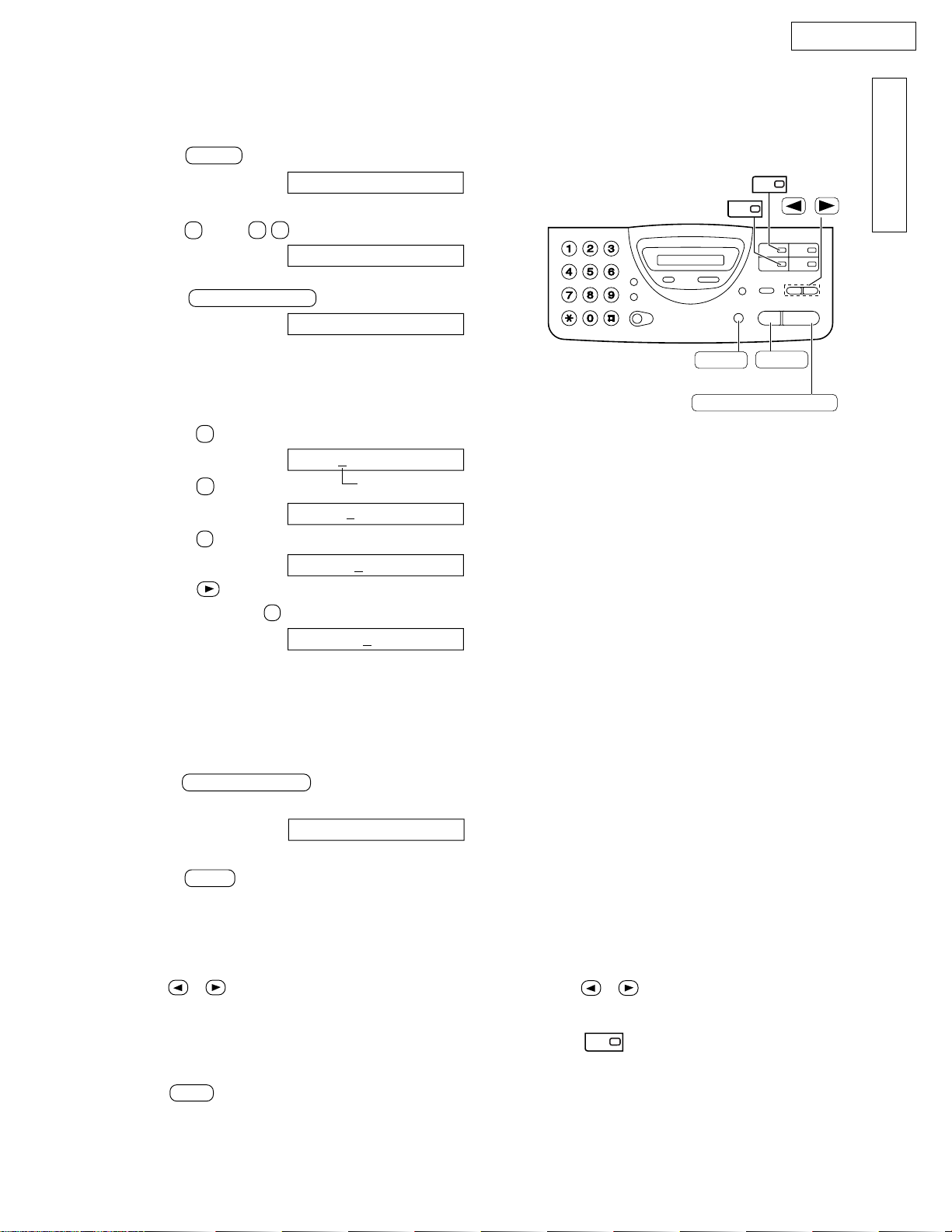
2. CONTROL PANEL
To select a resolution
Dial keypad
Hookswitch
To change the receive
mode
Display panel
The arrow indicator on the
display points to your selected
mode
To print a quick
reference
For the Speed Dial
For the Telephone Directory with
Alpha-Search
For the One-Touch Dial
Command keys
F
C
E
B
D
A
I
L
H
G
S
R
Q
P
TONE
To change from pulse to tone
during dialing
O
K
N
J
M
Z
V
Y
U
X
T
W
To redial the last number dialed
To insert a pause during dialing
RESOLURESOLUTIONON
H
FFLLAASSH
REDIAL/ PAUSE
MONITOR
To dial without lifting the
handset.
TEL
FAX
RECEIVE MODE RECEIVE MODE
DIRECTECTORY
HELP
MENU
To stop an operation or
To initiate or exit
programming.
1
4
2
5
STOP
3
6
LOWERLOWER
VOVOLUME
SEARCH
START/COPY/ SET
cancel programming
To insert a hyphen
To keep the telephone
number secret
To insert one character
or one space
To select stations 4 6
for the One-Touch Dial
To adjust volumes
To select feature settings
during programming.
To search for a stored
name
To initiate fax transmission,
reception or copying.
To store a setting during
programming.
- 12 -
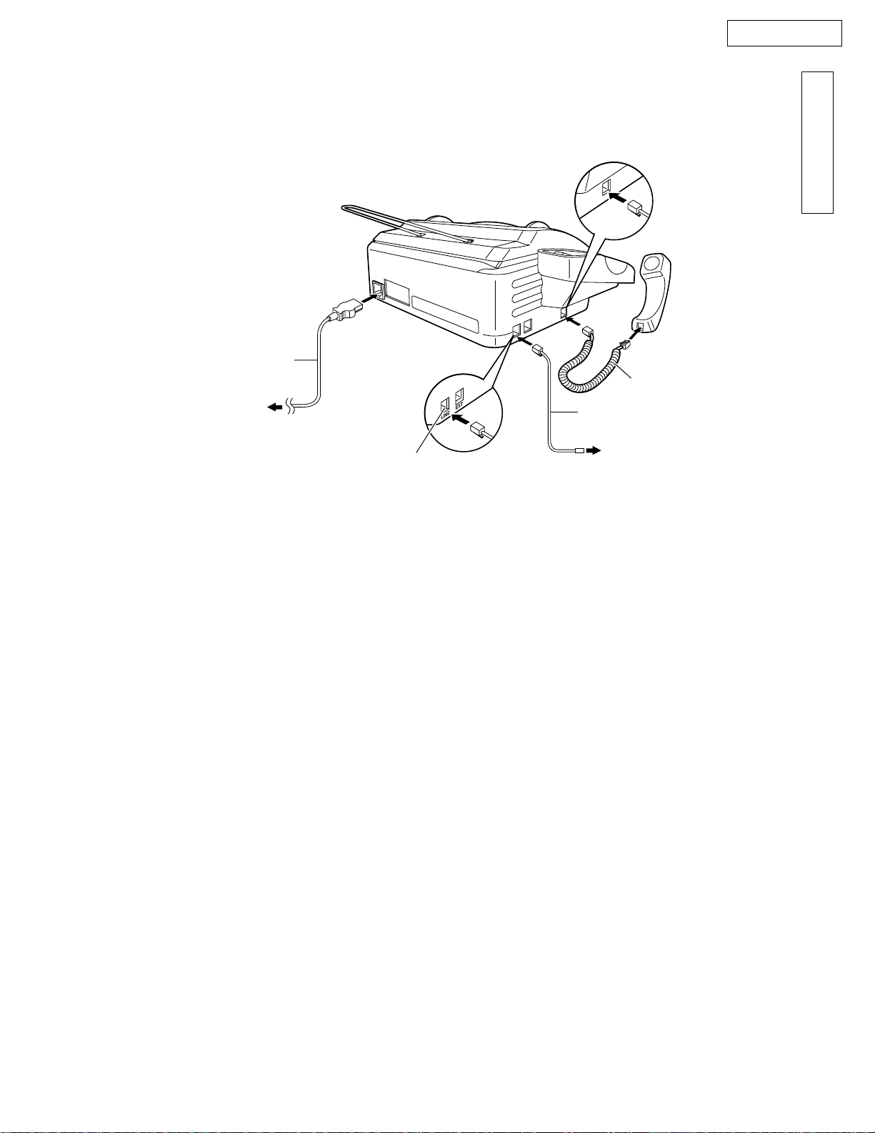
KX-FT21LA
Power cord
To the power
outlet (120V)
CONNECTIONS
Connect to LINE .
INTRODUCTION
Handset cord
Telephone
line cord
To the single
telephone line
Note:
When you operate this products, the power outlet should be near the product and easily accessible.
- 13 -
KX-FT21LA
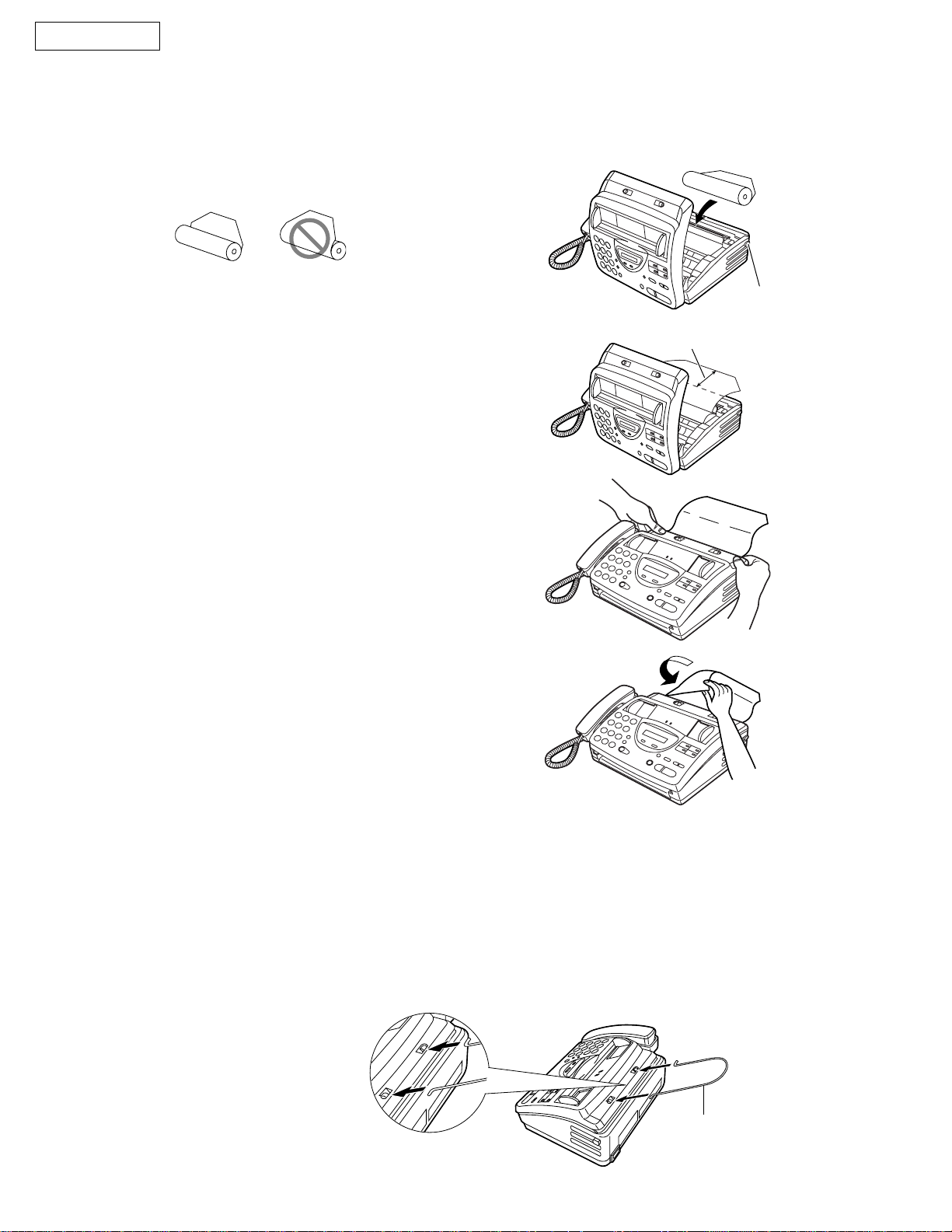
INST ALLATION
3. INSTALLING THE RECORDING P APER
1
2
3
Open the cover by pressing the cover open button
and install the recording paper roll.
correct
If the paper is secured with glue or tape, cut
approximately 15 cm (6 inches) from the
beginning.
Pull the leading edge of the paper approximately
10 cm (4 inches) out of the unit.
Make sure that there is no slack in the
paper roll.
Close the cover securely by pushing down on
both ends.
incorrect
Cover open
button
10 cm
4
Note:
Tear off the excess paper by pulling it
towards you.
Only use the included roll of paper or specified recording paper, or else the print quality may be
affected and/or excessive thermal head wear may occur.
For accessory order information.
When the power cord is connected, everytime you close the cover a message will be printed. If the recording
paper is set to the wrong side, the message will not be printed. Install the paper correctly.
Document stacker
Install the document stacker.
- 14 -
Document stacker
KX-FT21LA
4. SETTING YOUR LOGO
The logo can be your company, division or name.
Press MENU .
1
Display: SYSTEM SET UP
(PROG. SISTEMA)
Press # , then 0 2 .
2
Press ST ART/COPY/SET .
3
Enter your logo, up to 30 characters, by using
4
the dial keypad. See the next page for details.
Example: Bill
1. Press 2 twice.
2. Press 4 six times.
3. Press 5 six times.
YOUR LOGO
(SU LOGO)
LOGO=
LOGO=B
LOGO=B
i
Cursor
1
2
MENU
START/COPY/SET
STOP
(Delete)
/
INTRODUCTION
LOGO=Bi
4. Press to move the cursor to the next
space and press 5 six times.
LOGO=Bill
To enter the same number key continuously,
move the cursor to the next space.
Press ST ART/COPY/SET .
l
5
SETUP ITEM [ ]
(NO. PROG. [ ])
Press MENU .
6
T o correct a mistake
Press or to move the cursor to the incorrect
character, then make the correction.
T o delete a character
Move the cursor to the character you want to delete and
press STOP .
To insert a character
1. Press or to move the cursor to the
position to the right of where you want to
insert the character.
2. Press (One-Touch Dial key 2) to insert a
space and enter the character.
2
Note: Words in blankets ( ) are Spanish. A translated version for each market is available with this
model series.
- 15 -
KX-FT21LA
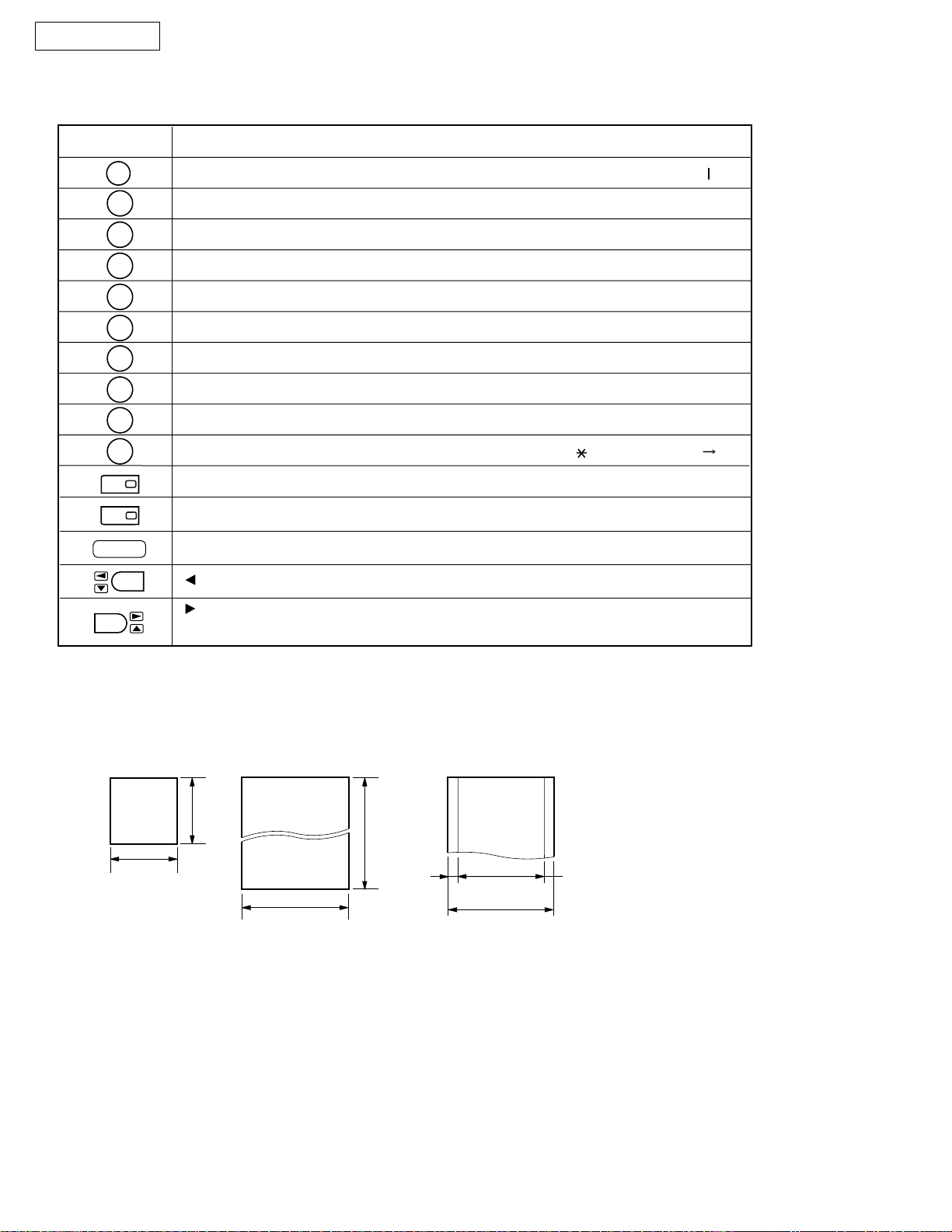
T o select characters with the dial keypad
Pressing the dial keys will select a character as shown below.
Keys
1
2
3
4
5
6
7
8
9
0
1
2
STOP
1
A
D
G
J
M
P
T
W
0
HYPHEN key (Used to insert a hyphen.)
INSERT key (Used to insert one character or one space.)
Delete key (Used to delete a character.)
key (Used to move the cursor to the left.)
]
[
C
B
F
E
I
H
L
K
O
N
R
Q
V
U
Y
X
()<>
}
{
b
a
e
d
h
g
k
j
n
m
p
S
u
t
w
Z
_
+
c
2
f
3
i
4
l
5
o
6
q
rs7
v
8
x
yz9
!"#$%&
Characters
/=, . :;?
,
_
\
@^
’
key (Used to move the cursor to the right.)
To enter another character using the same number key, move the cursor to the next space.
Documents you can send
Minimum size
Maximum size
(5")
128 mm
128 mm
(5")
216 mm
1
(8
/2")
Note:
Remove clips, staples or other similar fastening objects.
Check that ink, paste or correction fluid has dried.
Do not send the following types of documents. Use copies for fax transmission.
–Chemically treated paper such as carbon or carbonless duplicating paper
–Electrostatically charged paper
–Heavily curled, creased or torn paper
–Paper with a coated surface
–Paper with a faint image
– Paper with printing on the opposite side that can be seen through the front (e.g. newspaper)
Effective scanning area
")
8
/
5
(23
600 mm
4 mm
Scanned
area
208 mm (83/16")
Paper width
216 mm (81/2")
Document weight
Single sheet:
45 g/m2 to 90 g/m
2
(12 lb. to 24 lb.)
Multiple sheets (up to
10 sheets):
60 g/m2 to 75 g/m
2
(16 lb. to 20 lb.)
- 16 -
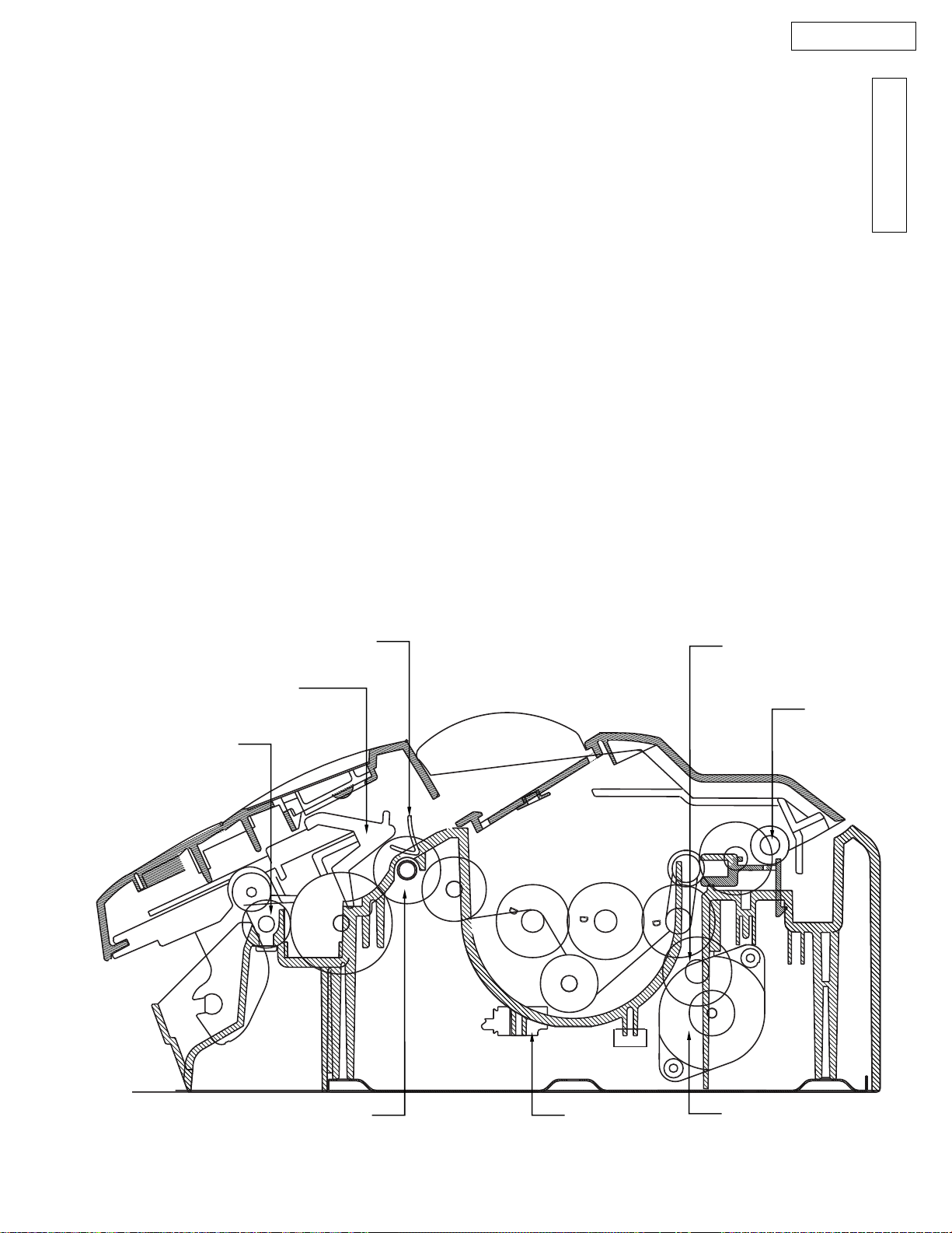
KX-FT21LA
Document Exit
Roller
Separation Roller
SWITCH 3
MOTOR
Read Position
Sensor
Document Sensor
Recording Paper
Sensor
Platen Roller
MAINTENANCE ITEMS AND COMPONENT LOCATIONS
1. OUTLINE
MAINTENANCE AND REPAIRS ARE PERFORMED USING THE FOLLOWING STEPS.
1) Periodic maintenance
Inspect the equipment periodically and if necessary, clean any contaminated parts.
2) Check for breakdowns
Look for problems and consider how they arose.
If the equipment can be still used, perform copying, self testing or communication testing.
3) Check equipment
Perform copying, self testing and communication testing to determine if the problem originates from the transmitter,
receiver or the telephone line.
4) Determine causes
Determine the causes of equipment problem by troubleshooting.
5) Equipment repairs
Repair or replace the defective parts and take appropriate measures at this stage to ensure that the problem will not
recur.
6) Confirm normal operation of the equipment
After completing the repairs, conduct copying, self testing and communication testing to confirm that the equipment
operates normally.
7) Record keeping
Make a record of the measures taken to rectify the problem for future reference.
INTRODUCTION
2. MAINTENANCE CHECK ITEMS/COMPONENT LOCATIONS
- 17 -
KX-FT21LA
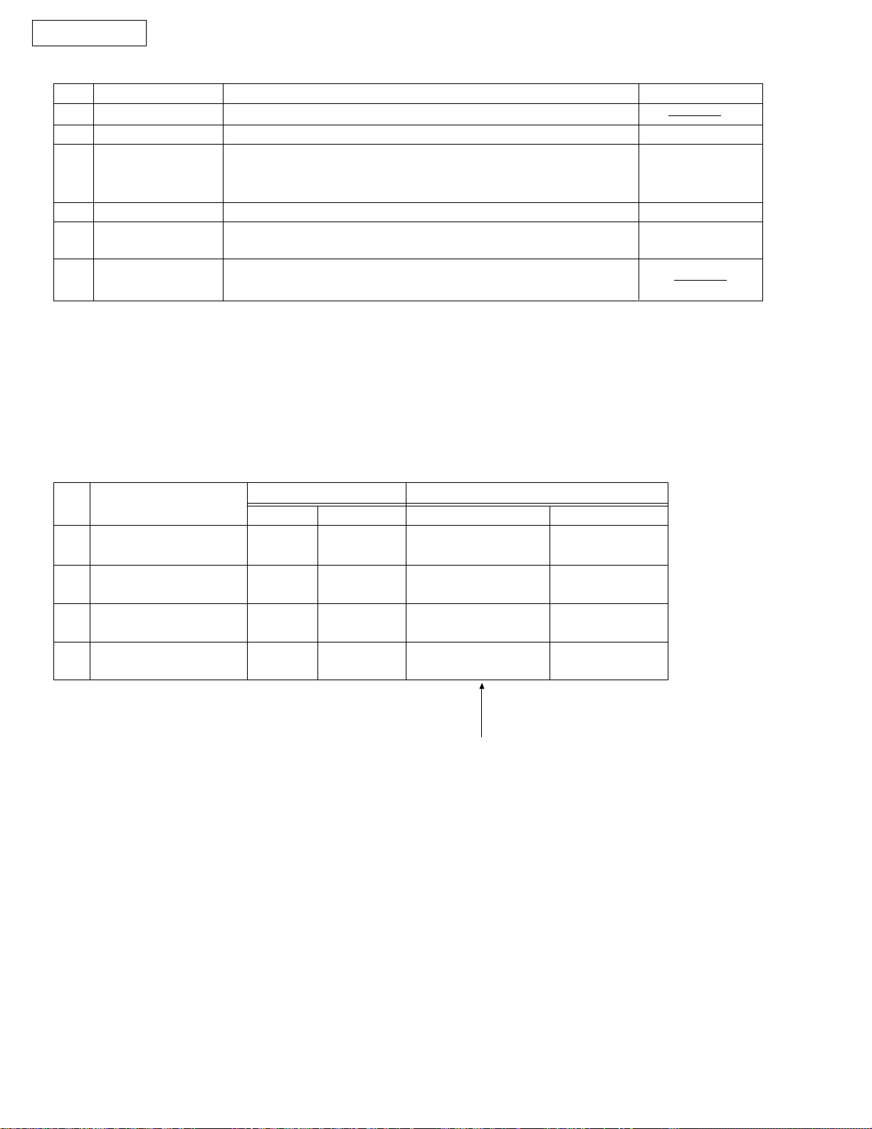
2.1 MAINTENANCE LIST
NO.
1
2
3
4
5
6
OPERATION
Document Path
Rollers
Thermal Head
Glass
Sensors
Abnormal, wear and
tear or loose parts
2.2 MAINTENANCE CYCLE
No.
1
Separation Roller
(Ref. No. 89)
Separation Rubber
2
(Ref. No. 85)
Feed Rollers
3
(Ref. No. 65)
Thermal Head
4
(Ref. No. 55)
Item
CHECK
Remove any foreign matter such as paper.
If the roller is dirty, clean it with a damp cloth then dry thoroughly.
If the thermal head is dirty, clean the printing surface with a cloth
moistened with denatured alcohol (alcohol without water), then dry
thoroughly.
If the glass is dirty, clean the glass with a dry soft cloth.
Document sensor (PS1), Read position sensor (PS2), Recording
paper/cover open sensor (SW1).
Exchange the part.
Check if the screws are tight on all parts.
Cleaning Replacement
Cycle
3 months
3 months
3 months
3 months
Procedure
See p. 19.
See p. 19.
See p. 19.
See p. 20.
Cycle
7 years
(100,000 documents)
7 years
(100,000 documents)
7 years
(100,000 documents)
7 years
(100,000 documents)
Procedure
See p. 103.
See p. 98.
See p. 103.
See p. 104.
REMARKS
See page 19.
See pages 20
and 104.
See page 19.
See page 79.
These values are only standard ones and may vary
depending on usage conditions.
- 18 -
KX-FT21LA
3. MAINTENANCE
3.1 CLEANING THE DOCUMENT FEEDER UNIT
If misfeeding occurs frequently or if dirty patterns or black bands appear on a copied or transmitted document,
clean the document feeder.
1
2
3
4
5
Disconnect the power cord and the telephone
line cord.
Open the cover by pressing the cover open button.
Clean the document feeder rollers, sub roller and
rubber flap with a cloth moistened with isopropyl
rubbing alcohol, and let all parts dry thoroughly.
Clean the white plate and glass with a soft dry cloth.
Close the cover securely by pushing down on both
ends.
Separation roller
Cover
Sub roller
Telephone
line code
Power cord
Document
feeder rollers
INTRODUCTION
6
Caution:
or tissues, to clean the inside of the unit.
Connect the power cord and the telephone line
cord.
Do not use paper products, such as paper towels
Cover open button
- 19 -
KX-FT21LA
3.2 CLEANING THE THERMAL HEAD
If dirty patterns or black bands appear on a copied or received document, clean the thermal head.
1
2
3
4
5
Caution:
a dry cloth and do not touch the thermal head directly with
your fingers.
Disconnect the power cord and the telephone
line cord.
Open the cover by pressing the cover open button.
Clean the thermal head with a cloth moistened with
isopropyl rubbing alcohol, and let it dry thoroughly.
Close the cover securely by pushing down on both
ends.
Connect the power cord and the telephone line
cord.
To prevent a malfunction due to static electricity, do not use
Thermal head
Cover open
button
Caution:
Do not push on
the black cover
3.3 CLEANING THE PICK UP ROLLER ........Refer to page 103.
- 20 -

TROUBLESHOOTING GUIDE
Page
1. Troubleshooting Summary .................................................................... 22
1-1. Troubleshooting..................................................................... 22
1-2. Precautions ........................................................................... 22
2. User Recoverable Errors....................................................................... 23
3. Troubleshooting Details................................................................... 25~82
KX-FT21LA
TROUBLESHOOTING GUIDE
3-1. Outline................................................................................... 25
3-2. Starting troubleshooting......................................................... 25
3-3. Table of troubleshooting items............................................... 26
3-4. Simple check list.................................................................... 27
3-5. ADF section..................................................................... 28~36
3-6. Communication section ................................................... 37~58
3-7. Digital board section ........................................................ 59~70
3-8. Analog board section....................................................... 71~73
3-9. Power supply section ...................................................... 74~77
3-10.Operation board section ........................................................ 78
3-11.Sensor section ...................................................................... 79
3-12.Read section ................................................................... 80~81
3-13.Thermal head section ............................................................ 82
4. Programming and Lists ................................................................... 83~87
5. Test Functions ................................................................................ 88~89
6. Journal 3 ........................................................................................ 90~91
- 21 -
KX-FT21LA
1. TROUBLESHOOTING SUMMARY
1-1. TROUBLESHOOTING
After confirming the problem by asking the user, troubleshoot according to the instructions and observe the following
precautions.
1-2. PRECAUTIONS
1) If there is trouble with the print quality or the paper feed, first check if the installation space and the print
paper meets the specifications, the paper selection lever/paper thickness lever is set correctly, and the paper is
set correctly without any slack.
2) Before troubleshooting, first check that the connectors and cables are connected correctly (not loose).
If the problem occurs randomly, check it very carefully.
3) When connecting the AC power cord with the unit case and checking the operation, exercise utmost care when
handling electric parts in order to avoid electric shock and short-circuits.
4) After troubleshooting, double check that you have not forgotten any connectors, left any loose screws, etc.
5) Always test to verify that the unit is working normally.
1. 3 WHEN YOU DON'T KNOW HOW TO OPERATE THE UNIT, USE THE HELP FUNCTION
• How to use: 1. Press HELP .
2. Press or until the desired item is displayed.
3. Press START/COPY/SET .
- 22 -
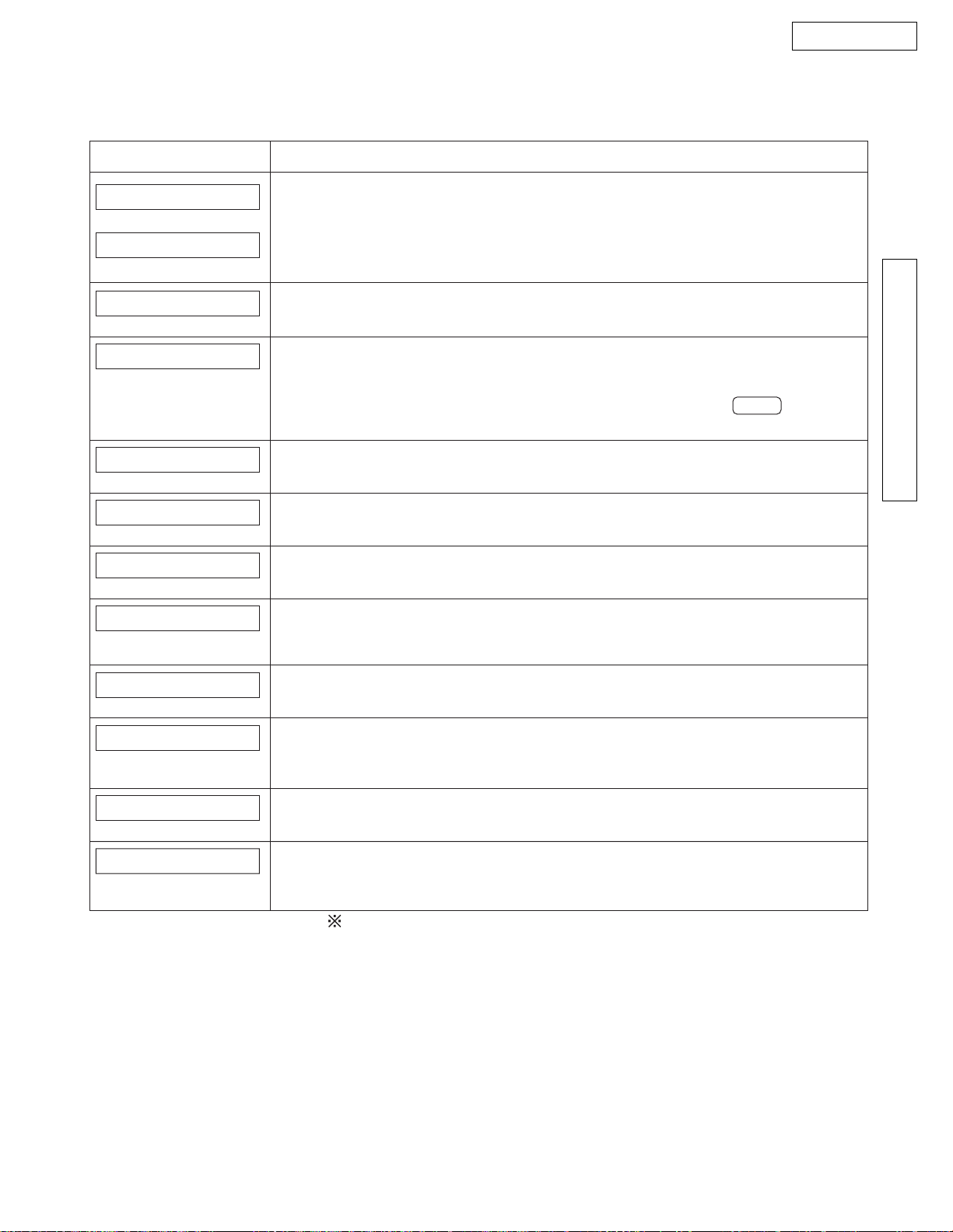
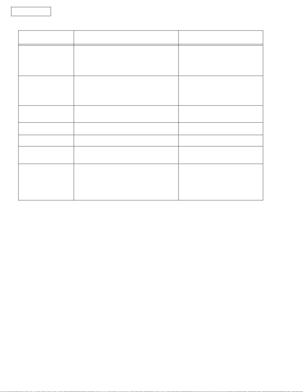
2. USER RECOVERABLE ERRORS
If the unit detects a problem, the following messages will appear on the display.
Display Message Cause & Remedy
KX-FT21LA
CALL SERVICE 1
(LLAME SERVICIO 1)
CALL SERVICE 2
(LLAME SERVICIO 2)
CHECK COVER
(REVISAR LA TAPA)
CHECK DOCUMENT
(REVISAR DOC.)
CHECK MEMORY
(REVISAR MEMORIA)
NO RESPONSE
(NO RESPUESTA)
OUT OF PAPER
(SIN PAPEL)
POLLING ERROR
(ERROR DE RECUP.)
There is something wrong with the unit. Contact our service personnel.
[This error is displayed when the thermal head dose not warm up. Check the
thermistor on the thermal head and connector lead. (for technicians)]
TROUBLESHOOTING GUIDE
The cover is open. Close it.
The document is not fed into the unit properly. Reinsert the document. If misfeeding
occurs frequently, clean the document feeder rollers and try again. If the problem
remains, adjust the feeder pressure.
Attempted to transmit a document longer than 600 mm. Press the STOP button to
remove the document. Divide the document into two or more sheets and try again.
Memory (telephone numbers, parameters, etc.) has been erased. Re-program.
[The backup battery on the top of the digital board may be low or dead, so check it.]
The other party’s fax machine is busy or ran out of recording paper. Try again.
The unit runs out of recording paper. Install a recording paper.
The other party’s fax machine does not have a polling feature. Check with the other
party.
REDIAL TIME OUT
(CANCELA REDISC)
REMOVE DOCUMENT
(REMOVER DOC.)
TRANSMIT ERROR
(ERROR DE TRANS.)
UNIT OVERHEATED
(SOBRECALENTADO)
The other party’s fax machine is busy or ran out of recording paper. Try again.
The document is jammed. Remove the jammed document.
[Alternately, turn off service code #559 to enable sending of documents longer than
600 mm.]
A transmission error occurred. Try again.
The unit is too hot. Let the unit cool down.
[If many copies are nearly all black, this message will be displayed. When this occurs,
open the front cover and let the unit cool down.]
The explanations given in the [ ] are for serviceman only.
Note:
Use this USER RECOVERABLE ERRORS table when referring to LCD
messages printed in this Service Manual.
Words in blankets ( ) are Spanish. A translated version for each market
is available with this model series.
- 23 -
KX-FT21LA
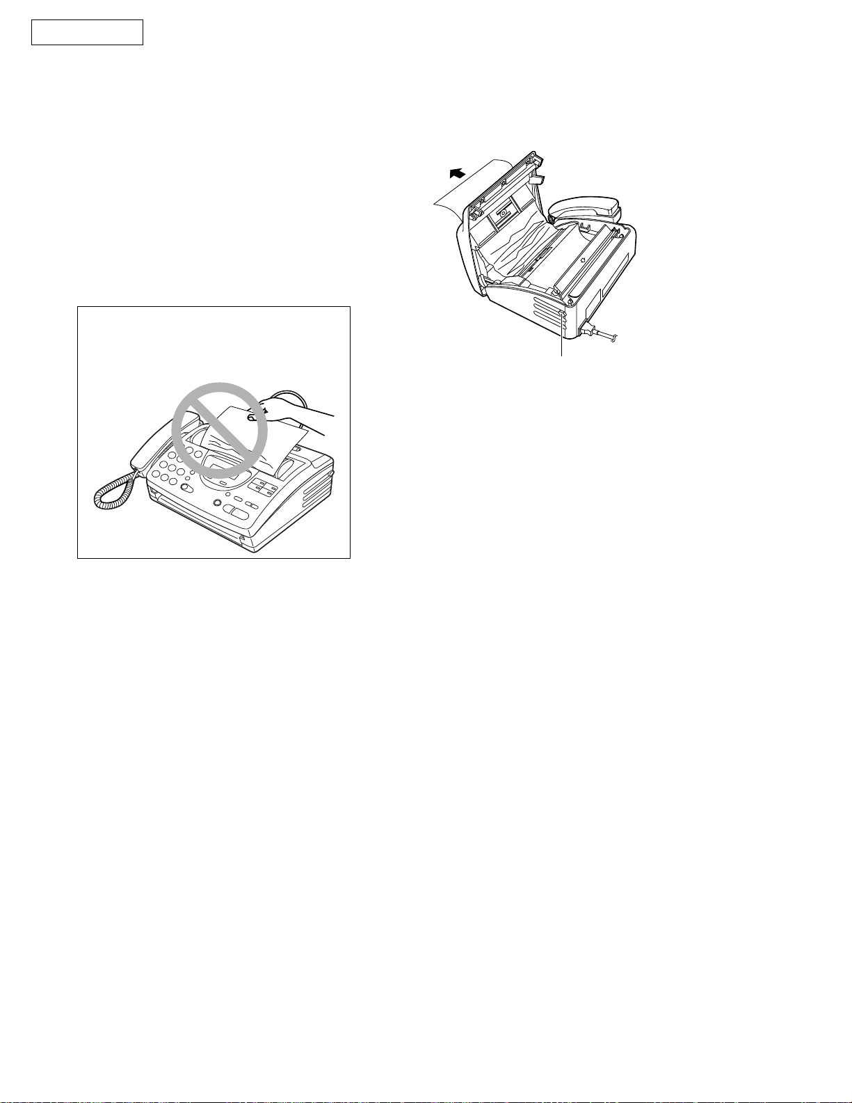
Document jam
If the unit does not release the document during feeding, remove the jammed document as follows.
Open the cover by pressing the cover open
1
button.
Remove the jammed document carefully.
2
Close the cover securely by pushing down
3
on both ends.
Note:
• Do not pull out the jammed paper forcibly.
before opening the cover.
Cover open button
- 24 -
3. TROUBLESHOOTING DETAILS
3-1. OUTLINE
Troubleshooting guide provides a logical path of deduction to assist in locating a fault and suggests methods
of restoring the unit to full working condition. Use the reported symptoms of the fault to determine the best
troubleshooting method. Even difficult faults can be tracked to a specific block or area, for example, the "Digital
Board" or "Image Sensor".
A variety of fault descriptions from customers often point to the same area and, for this reason, careful analysis of
the reported symptoms is required. After every repair, test all functions to ensure no problems are evident.
KX-FT21LA
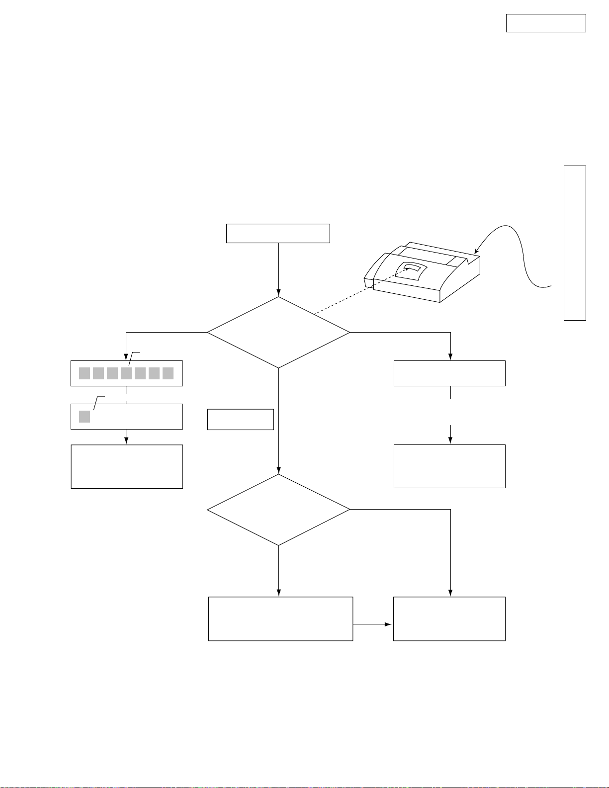
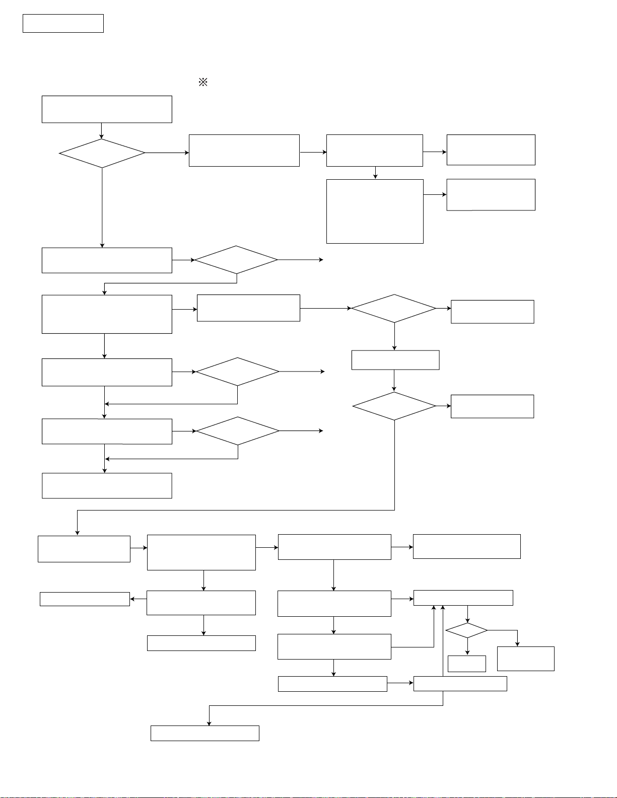
3-2. STARTING TROUBLESHOOTING
Select the appropriate troubleshooting method according to the symptoms.
Power on.
Plug in the AC cord.
Check LCD.
LCD
or
Blinking
See the digital board
section.
(See page 59.)
slightly changes
LCD
12:00AM
good
LCD
Blank LCD means that the power line
is broken (open-circuit).
See the digital board
section.
(See page 59.)
Blank
TROUBLESHOOTING GUIDE
AC
Already known symptom
No
Determine the symptom using
the check list. (See page 25.)
- 25 -
Yes
See the table for
troubleshooting items.
KX-FT21LA
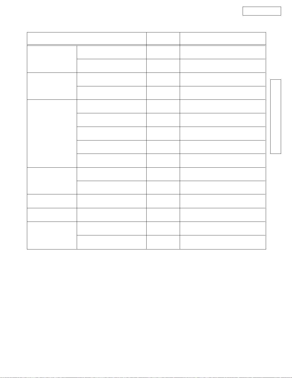
3-3. TABLE OF TROUBLESHOOTING ITEMS
FUNCTION SYMPTOM SEE THIS PAGE.
Printing
ADF
(Auto Document Feeder)
Abnormal
mechanical sound
Power supply
Operation panel
Sensor
Communication
FAX, TEL
(Analog/Digital board)
Skewed receiving image
Expanded print
Image is distorted.
Black or White vertical lines appear.
No feed
Paper jam
Multiple feed
Skew
Abnormal sound from the product
Voltage output is abnormal.
Keys are not accepted.
If the electric circuit is the cause,
"REMOVE DOCUMENT" will be displayed.
Cannot communicate by fax.
Error code is displayed.
Cannot talk.
DTMF tone doesn't work.
Handset/Monitor sound, volume
34
34
35
33
28
29
30
31
35
74
78
79
38
38
The analog board may cause these
symptoms.
}
(Refer to page 72.)
- 26 -
3-4. SIMPLE CHECK LIST
KX-FT21LA
FAX operation
Copy operation
Telephone operation
Operation panel
FUNCTION
Transmission
Receiving
FINE mode
HALF TONE mode
Handset transceiver / receive
Monitor sound
Ringer sound
Dial operation
Volume operation
Key check
JUDGEMENT
OK • ^ NG
OK • ^ NG
OK • ^ NG
OK • ^ NG
OK • ^ NG
OK • ^ NG
OK • ^ NG
OK • ^ NG
OK • ^ NG
OK • ^ NG
REFERENCE
TROUBLESHOOTING GUIDE
SERVICE CODE 561
Sensor
Clock
External Telephone
LCD check
Sensor check
Handset transceiver/receiver
Remote control
OK • ^ NG
OK • ^ NG
OK • ^ NG
OK • ^ NG
OK • ^ NG
SERVICE CODE 558
SERVICE CODE 815
Is the time kept correctly?
Check with another clock.
Change to FAX receiving by pressing • – 9.
(Refer to user mode #41 on page 57.)
• ¦ Check according to the service code referring
to the Test function on pages 88.
- 27 -
KX-FT21LA
3-5. ADF (Auto document feed) SECTION
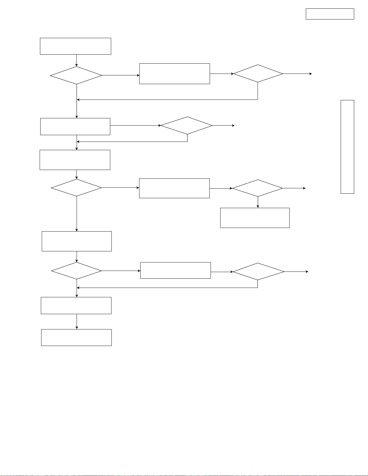
(1) No document feed
When setting the document,
confirm a beep tone.
OK?
YES
Clean the separation roller.
(page 103)
Does the separation roller
rotate? [Use the motor test
function (page 88)]
YES
Adjust the separation spring
and clean or replace the pad.
YES
NO
When using thin paper etc., if the document will not feed.
refer to the feed pressure adjustment (page 92).
Check the separation
spring for distortion.
OK?
NG
NO
Check the motor and
connector.
NO
OK?
NG
OK
OK
OK
Check the sensor
lever movement.
Check the sensor
[Use the sensor check
function (page 88)]
and digital board.
(pages 59 and 79)
END
Check the gear.
END
OK
OK?
OK?
YES
Replace the sen-
NG
sor lever.
NG
Replace the defective parts.
NG
Replace the motor
and connector.
NG
Replace the gear.
Replace the separation
roller unit.
YES
Replace the operating cover
unit.
To digital board
section. (page 59)
NO
Repair.
NO
Is the phase signal from
pins 126-130 of IC4 output?
Is the solder at pins 126130 of IC4 OK?
Replace IC8.
OK?
NG
YES
YES
OK
YES
Is the voltage at emitter
of Q7 +24 V?
Is the voltage at collector
of Q7 +24 V?
Is the voltage at pin 11 of
IC8 less than 2V?
END
Replace Q7.
YES
NO
YES
YES
NO
Check the power supply
unit section. (page 74)
YES
NO
Replace IC8.
YES
NO
OK?
END
NO
OK?
Replace the
motor.
END
- 28 -
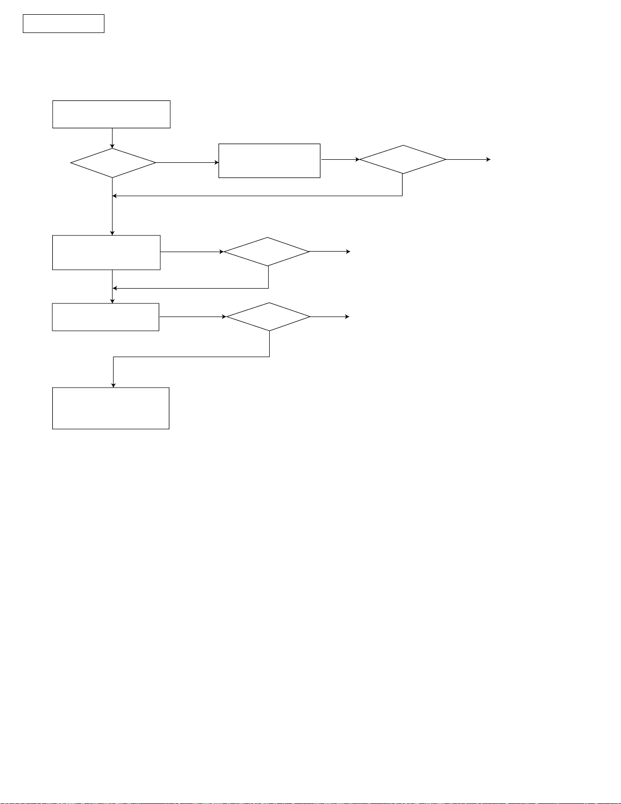
(2) Paper JAM
KX-FT21LA
Open the lid and check
the feed route.
OK?
YES
Clean each roller.
(page 103)
Check each sensor’s
movement.
OK?
YES
Check the paper jam for cause.
NO
Confirm if the tip of the read position
sensor lever works smoothly. [Use the sensor test function (page 88).]
NO
Clean or replace the
defective parts.
OK?
NG
Repair or replace the
sensor lever.
NG
OK
END
NG
Go to the sensor section.
(page 79)
OK?
OK?
OK
OK
Check if the sensor
reacts while the flag is
moving.
END
END
TROUBLESHOOTING GUIDE
Check each roller’s
mount.
OK?
YES
Check the white plate.
NG
Replace the white plate.
Check if the separation, feed and pinch rollers are
attached correctly.
NO
Repair the defective parts.
NG
OK?
OK
END
- 29 -
KX-FT21LA
(3) Multiple feed
When using thick paper, etc., if the document will not feed.
refer to the feed pressure adjustment (page 92).
Check the separation pad.
OK?
YES
Check if the separation
spring is distorted.
Clean each roller.
(page 103)
Replace the separation
pad, roller and pressure
spring.
NO
Confirm whether the pad is dirty or not and if it
is attached correctly.
Clean or replace the
defective parts.
NG
NG
OK?
OK?
OK
OK
END
END
NG
OK?
OK
END
- 30 -
 Loading...