

Panasonic FA-MA301 Service manual

FA-MA301 Back to Model List
(FA-MA301) LCC
Contents
WARNING
I. Introduction
1.1 Specifications.......................................................................................... 1-1
1.2 Features.................................................................................................. 1-1
1.3 Exterior ................................................................................................... 1-2
1.4 Component Location............................................................................... 1-2
II. Mechanical components
2.1 Operation of LCC elevating drive............................................................ 2-1
2.2 Operation of the LCC.............................................................................. 2-2
III. Maintenance
3.1 Maintenance components....................................................................... 3-1
3.2 Disassembly and Assembly.................................................................... 3-2
Mechanical
components
Maintenance Introduction
Electrical
IV. Electrical
4.1 Electrical components operation............................................................. 4-1
4.2 Signal information ................................................................................... 4-3
V. Troubleshooting
5.1 Self-diagnosis / Machine malfunction ..........
5.2 Service mode...............................................
Refer to System console service manual
Refer to System console service manual
VI. Installation procedure
6.1 Unpacking............................................................................................... 6-1
6.2 Installation procedure ............................................................................. 6-2
6.3 Adjustment.............................................................................................. 6-3
Schematic diagram (LCC)
Trouble
Shooting
Installation

WARNING
This service information is designed for experienced repair technicians only and
is not designed for use by the general public.
It does not contain warnings or cautions to advise non-technical individuals of
potential dangers in attempting to service a product.
Products powered by electricity should be serviced or repaired only by experienced
professional technicians. Any attempt to service or repair the product or products
dealt with in this service information by anyone else could result serious injury or
death.
(For USA)
This manual was developed and is supplied to authorized servicing dealers by
Panasonic Communications & Systems Co. for the sole purpose of providing
information necessary for the equipment's proper support. It is intended that this
information be confidential and may not be reproduced without prior written consent
from Panasonic Communications & Systems Co. Panasonic Communications &
Systems Co. reserves the right to change any information enclosed herein without
prior notification.
This manual was developed and is supplied to authorized servicing dealers by
Panasonic Co. for the sole purpose of providing information necessary for the
equipment's proper support. It is intended that this information be confidential
and may not be reproduced without prior written consent from Panasonic Co.
Panasonic Co. reserves the right to change any information enclosed herein without
prior notification.
© February, 1999

Section I Introduction
1.1 Specifications
Type Large capacity paper feed cassette
Paper capacity 3000 sheets (20 lb / 80g/m
Paper weight Standard : 20 lb / 80 g/m
Range : 16 to 24 lb / 60 g/m2 to 90 g/m
Paper size Letter / A4 size width
Power source DC 24V ( Power source is supplied by copier main body)
Power consumption 20W
Dimensions 11.4" (W) x 17.5" (D) x 20.4" (H)
290 (W) x 445 (D) x 517 (H) mm
Weight 30.8 lb / 14 kg
Ambient conditions Temperature : 50 ~ 86 F / 10 ~ 30 degree
Relative humidity : 30 ~80 % RH
Applicable models FP-7728 / 7735 / 7742 / 7750
FP-D250/D350/D450/D600 Series
2
)
2
2
1.2 Features
• Large capacity design holds 3000 sheets.
• Easy to install using an outside connector directly to the copy machine.
Introduction
1-1
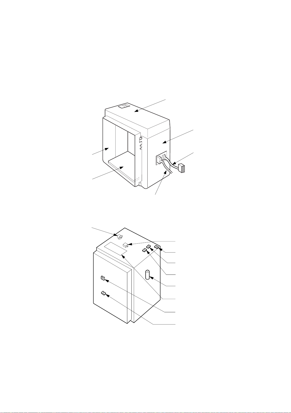
1.3 Exterior
Door
Paper feed table
Upper cover
Rear cover
Connecting cord
to the copy
machine frame
Junction
cord
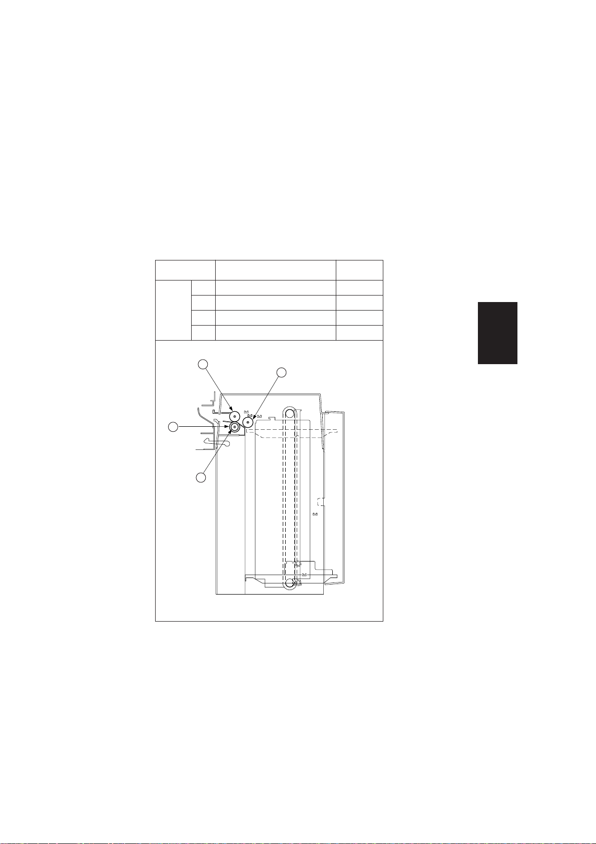
1.4 Component location
Paper feed motor
SV006
Paper feed solenoid
LCC sensor
Upper limit sensor
Paper detecting sensor
Elevator motor
Driver PCB
Door open /close sensor
Lower limit sensor
SV005
1-2
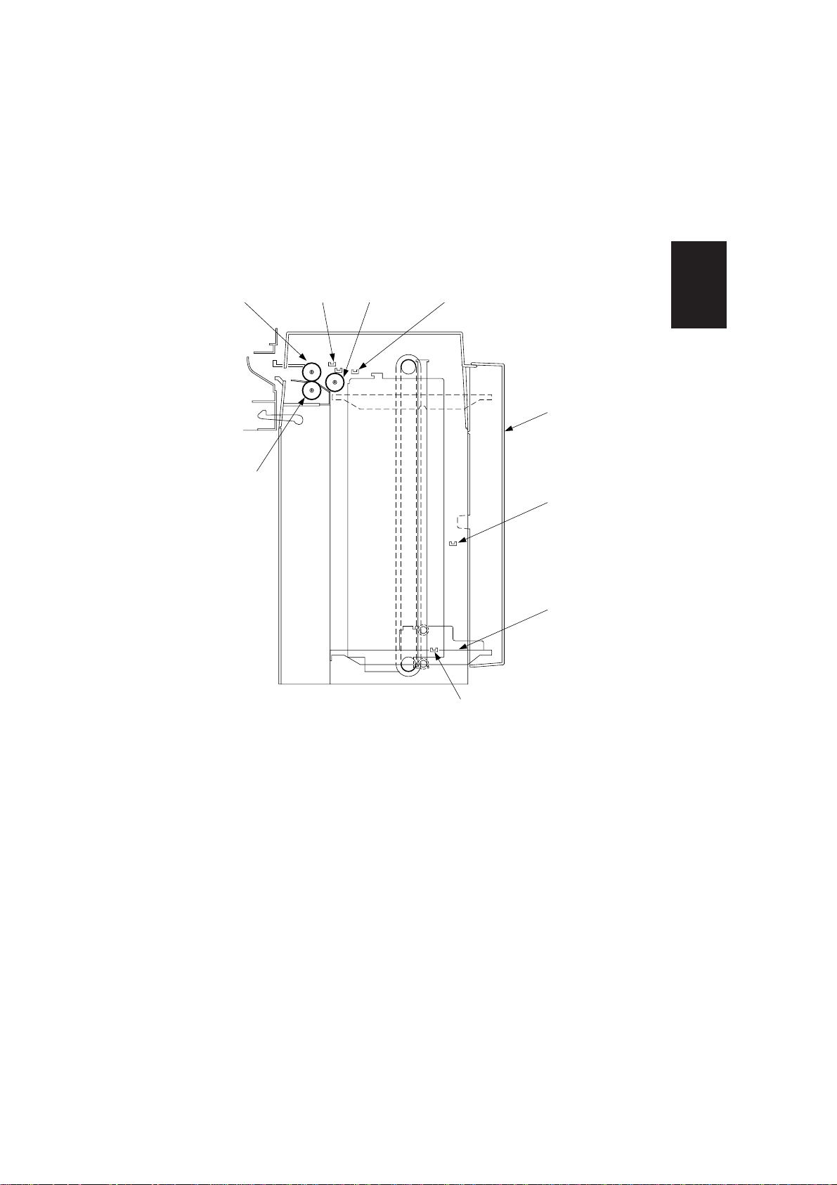
DFP roller
Upper limit
sensor
Pick up rollerPaper feed roller
Paper detecting sensor
Introduction
Door
Door open /
close sensor
Paper feed
table
Lower limit
sensor
SV001
1-3
Section II Mechanical components
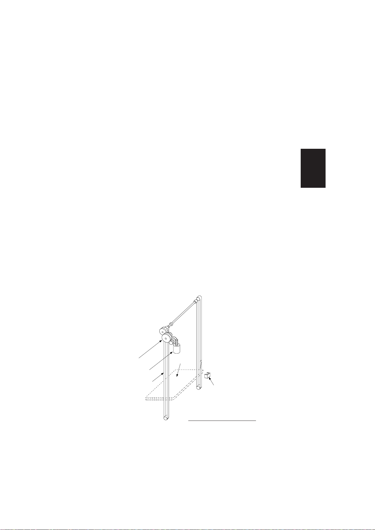
2.1 Operation of LCC elevating drive
The LCC system enables 3,000 sheets of paper to be put on the paper feed table.
Elevating operation of the table is as follows.
• When the elevator motor of the paper feed table rotates, the drive gear of the
elevator chain is driven by the middle gear and the elevator chain begins to
drive. The paper feed table, which is connected to the elevator chain, begins to
rise or to fall according to the direction the chain is driving.
• When the door closes, the paper feed table is lifted. When the lower limit sensor
detects the paper feed table, the sensor stops the elevator drive.
• When the door opens, the paper feed table is driven down. When the lower limit
sensor detects the paper feed table, the sensor stops elevator drive.
• When the paper is fed, and the sheets of paper on the paper feed table are
removed, the upper limit sensor turns OFF. The elevator motor rotates, and by
the rotation, the paper feed table is elevated.
When the upper limit sensor detects the paper, the elevator motor stops and the
upper limit of paper on the table is compensated.
Mechanical
components
Middle gear
Elevator motor
Elevator chain
Paper
feed
table
Lower limit sensor
Tray elevating mechanism
SV008
2-1
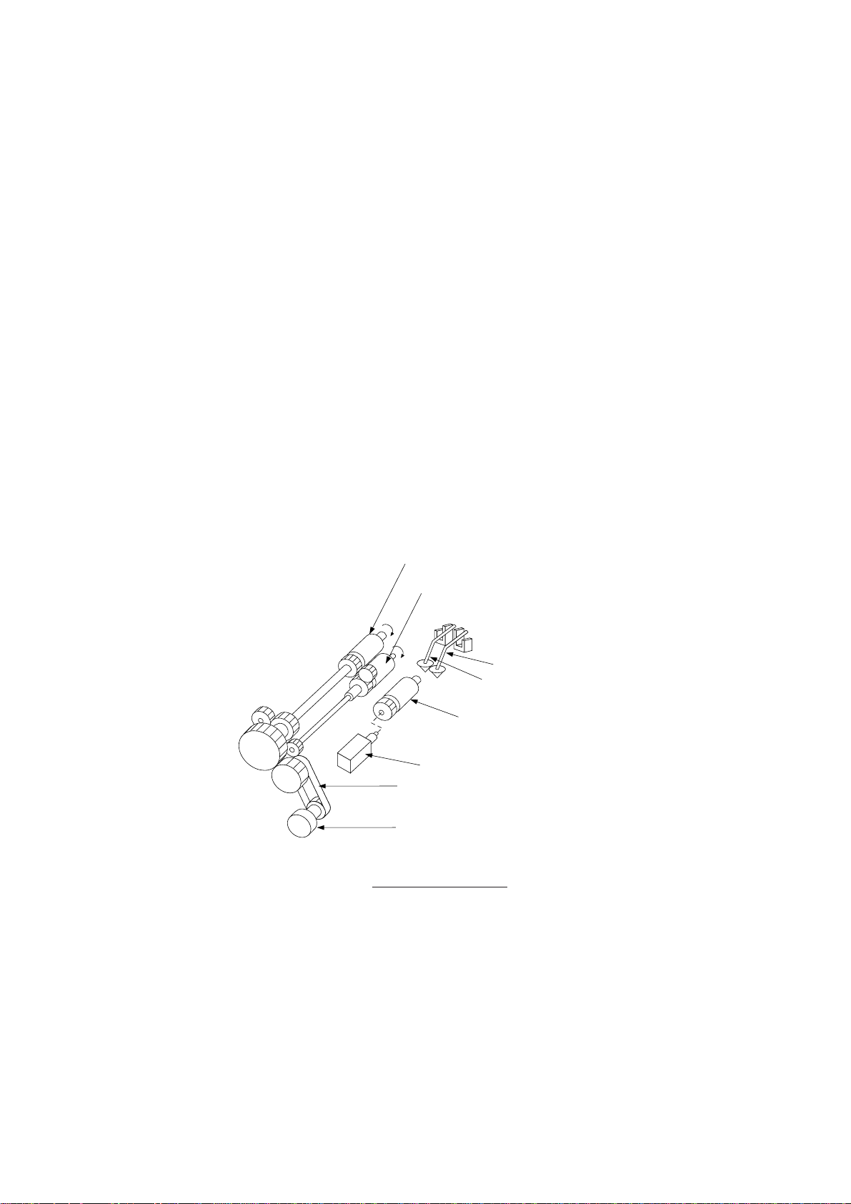
2.2 Operation of the LCC
As for the structure of LCC paper feed unit, please refer to the paper feed section in
the basic version of main body Service Manual of the copy machine.
• When the copy-start-key is pressed, and the paper feed motor rotates, the paper
feed roller and pick up roller are driven by the drive belt and gear.
• When the paper feed solenoid turns on, the pick up roller contacts the paper.
The paper on the paper feed table is fed to the main body of the copy machine
by the pick up roller and paper feed roller.
If paper is double fed, the lower sheet is returned by the DFP roller.
• When there is no paper on the paper feed table, the sensor lever enters a slot on
the table. In this way the paper detecting sensor detects a paper empty condition.
Paper feed roller
DFP roller
Paper detecting sensor
Upper limit sensor
2-2
Pick-up roller
Paper feed solenoid
Drive belt
Paper feed motor
Operation of LCC drive
SV009
Section III Maintenance
3.1 Maintenance components
The following is the replacement parts of LCC maintenance.
Block Section Part name
Pick-up roller
1
Paper feed roller
2
LCC
3
DFP roller
3
Torque limiter
4
2
4
1
Replacement
interval
120K
120K
120K
1200K
Maintenance
SV010
3-1
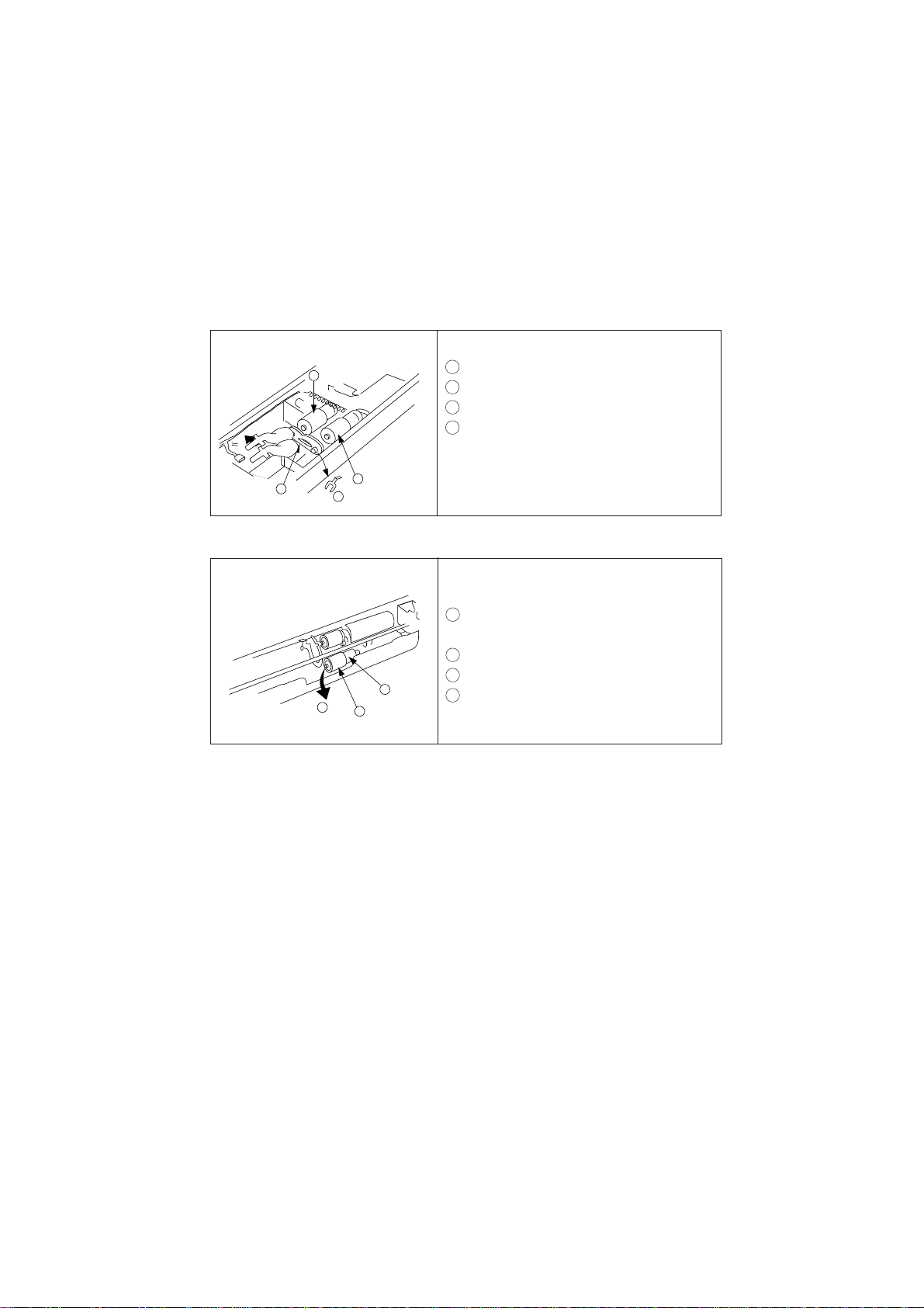
3.2 Disassembly / Assembly
1) Replacement of the pick-up roller / paper feed roller
1
Pick up roller
3
• Remove the upper cover.
1 Remove the touch ring.
2 Remove the bracket guide.
3 Remove and replace the pick-up roller.
4 Remove and replace the paper feed roller.
4
2
1
Paper feed roller
SV011
2) Replacement of the paper drawer double feed prevention roller/torque limiter
2
• Remove the front guide from the paper
feed side. ( 2 screws )
1 Remove the touch ring lowering the DFP
roller downward.
2 Remove the DFP roller.
3
1
2
SV012
3 Remove the torque limiter.
4 Check the direction of the torque limiter
3-2

Section IV Electrical
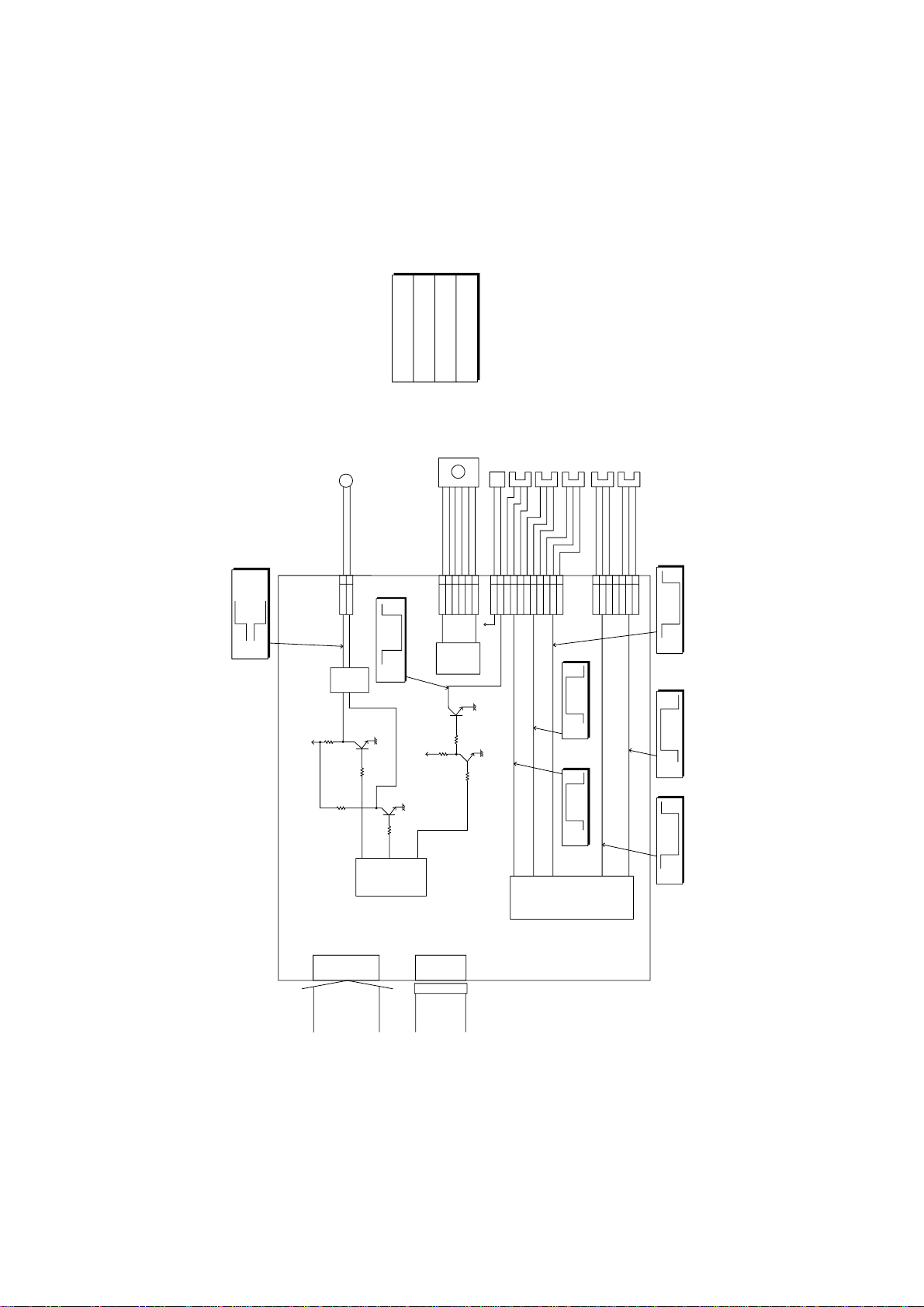
4.1 Electrical Components Operation
The circuit construction of the electrical components in LCC three thousand sheet
cassette is shown in the figure below.
• When the LCC door is opened, the door open/close detecting sensor detects
open/close and the signal from it is inputted into IC563. Then, the up/down signal
of the paper feed tray is transmitted from IC562 to transistor DT563 and IC564,
which sends an electric current to the up/down motor and rotates it downward.
The combination of transistor DT563 and DT564 signals controls the up and
down motion of the tray. It is transmitted to IC565 and starts the up/down motor.
• When the paper tray reaches the lower limit sensor, the sensor is actuated, and
the signal from it (LCLDSN is high) is inputted into IC563 to stop the downward
movement of the tray.
• When the door is closed after paper is installed on the paper tray, the signal from
the door open/close detecting sensor is inputted into IC563 and the tray goes
up.
• When the upper surface of paper reaches the upper limit, the sensor lever
attached to the paper limit sensor is lifted up. At this time, the paper upper limit
sensor signal (LCLBSN) becomes high. This signal is inputted into IC563 to stop
the elevator motor.
• When copying starts, the paper feed motor starts rotation and the paper feed
solenoid is turned on. Then the paper transfer roller is pushed against paper on
the paper tray, and the paper is sent to copier by the paper transfer roller and the
paper feed roller.
• When the amount of paper on the tray decreases, the upper limit sensor is turned
off. (Intercepted: 5V) In this condition, the elevator motor goes up and the
upper limit sensor is turned on (Unintercepted: 0V), the motor stops and the
upper surface position of paper in the tray is maintained.
• When there is no paper in the tray, the sensor lever falls into the slit hole on the
bottom plate. Then paper detecting sensor is turned off (Intercepted: 5V) and
detects no paper.
• The photosensors such as paper detecting sensor show high (5V) when the
sensor levers intercept the sensors and low (0V) when they do not. The voltage
is read by IC563 as the input signals.
Electrical
4-1
CN564
123456789
10
11
V
P
LCSOL
V
L
LCLBSN
GND
V
L
LCPESN
CN566
1234567
GND
LCDOSN
V
L
–
GND
LCLDSN
CN565
12345
6
LCMBB
COMB
LCMB
LCMAB
COMA
LCMA
V
L
GND
VLLCDSN
GND
CN563
1
2
LCLUM1
LCLUM2
24V0V24V
0V
LCLUM1
LCLUM2
IN1
IN2
ST
+5V
R585
Q561
R586
DT565
IC564
+24V
IC565
1
2
R582
+5V
R583
DT563
DT564
1
2
24
IC562
11
12
14
3
13
IC563
4
8
24V
0V
5V
0V
5V
0V
5V
0V
5V
0V
5V
0V
UP
DOWN
UP
DOWN
F4 MODE OUTPUT CHECK
ELEVATOR MOTOR
PAPER FEED
SOLENOID ON
PAPER FEED SOLENOID ON
F4-65:
F4-66: TRAY GOING UP
F4-67: TRAY GOING DOWN
PAPER FEED
MOTOR
PAPER FEED SOLONOID
UPPER LIMIT SENSOR
PAPER DETECTING SENSOR
LCC INSTALLATION SENSOR
NO PAPER
(INTERCEPTED)
DOOR OPEN/CLOSE DETECTING SENSOR
LOWER LIMIT SENSOR
LCC INSTALLED
(INTERCEPTED)
TRAY LOWER
LIMIT
(INTERCEPTED)
PAPER UPPER
LIMIT
(INTERCEPTED)
DOOR
CLOSED
(INTERCEPTED)
LCC DRIVER CIRCUIT
CONNECTING
CABLE
(TO COPIER)
CONNECTOR
(TO SYSTEM
CONSOLE
PAPER FEED)
4-2
 Loading...