

Panasonic FA-F350, FA-F355 Service manual

FA-F350/F355 Back to Model List
FA-F350/F355
Contents/Index
WARNING
I. Introduction
1.1 Specifications.......................................................................................... 1-1
1.2 Features.................................................................................................. 1-3
1.3 Exterior Parts .......................................................................................... 1-4
1.4 Structual Drawing ................................................................................... 1-4
1.5 Component Location............................................................................... 1-5
II. Operation
2.1 Outline .................................................................................................... 2-1
2.2 Mechanism ............................................................................................. 2-6
III. Maintenance
3.1 Maintenance chart .................................................................................. 3-1
3.2 Disassembly and Assembly.................................................................... 3-2
IV. Electrical
4.1 Electrical parts Operation ....................................................................... 4-1
4.2 Signal information ................................................................................... 4-6
4.3 Adjustment.............................................................................................. 4-11
V. Trouble Shooting
5.1 Self-diagnosis/Detection of malfunction ................................................. 5-1
5.2 Service mode.......................................................................................... 5-6
5.3 Self-checking .......................................................................................... 5-7
5.4 Error Code .............................................................................................. 5-10
VI. Unpacking/Installation
6.1 Installation requirements......................................................................... 6-1
6.2 Installation procedure ............................................................................. 6-2
Electrical Maintenance Operation Introduction
Trouble
Shooting
Installation
Unpacking/

WARNING
This service information is designed for experienced repair technicians only and
is not designed for use by the general public.
It does not contain warnings or cautions to advise non-technical individuals of
potential dangers in attempting to service a product.
Products powered by electricity should be serviced or repaired only by experienced
professional technicians. Any attempt to service or repair the product or products
dealt with in this service information by anyone else could result serious injury or
death.
(For USA)
This manual was developed and is supplied to authorized servicing dealers by
Panasonic Communications & Systems Co. for the sole purpose of providing
information necessary for the equipment's proper support. It is intended that this
information be confidential and may not be reproduced without prior written consent
from Panasonic Communications & Systems Co. Panasonic Communications &
Systems Co. reserves the right to change any information enclosed herein without
prior notification.
This manual was developed and is supplied to authorized servicing dealers by
Panasonic Co. for the sole purpose of providing information necessary for the
equipment's proper support. It is intended that this information be confidential
and may not be reproduced without prior written consent from Panasonic Co.
Panasonic Co. reserves the right to change any information enclosed herein without
prior notification.
© February, 1999
Section I Introduction
1.1 Specifications
Item
Loading Style Three-layer tray, descending style
Loading Method Face-up/Face-down loading
Copy Paper Size A,B series A3,A4,A4R,A5R,B4,B5,B5R,post Inch-series
LDR,LGL,LTR,LTRR,INV
Copy Paper Weight 12-32Ibs/50-128g/m
Number of Bins Tray for interruption copies/1-3 bins
Modes Staple mode, Non-staple mode, Sort-mode:Single copy
shift mode
Loading Capacity Interruption 50(S)30(L)
Non-staple sort 1bin: 300(S)150(L)
Staple Sort 1bin: 300(S)150(L)
(L) Ledger, Legal, Letter-R, A3, B4, A4R
(S) Letter, Invoice, A4, A5, B5
Staple plus Non-Staple Possible under certain conditions
Stacking
Paper Detecting 1-3 bins
Operation Part None
Display None
Size (W) (D) (H) 26.3”x22.9”x41.2” / 669x582x1,039mm (FA-F350)
Weight 76lbs./34.5kg(FA-F350), 79lbs/36kg(FA-F355)
Power Source 24VDC supplied from copier
Power Approx. 70W
Consumption
Offset stacking (Top sheet of paper for each set is shifted by 30mm)
26.3”x23.7”x41.2” / 669x603x1,039mm (FA-F355)
2
2bins: 1,000(S)500(L)
3bins: 200(S)100(L)
Max: 30(S)30(L)
2bins: 750(S)500(L)
Max: 30(S)30(L)
3bins: 200(S)100(L)
Max: 20(S)20(L)
Introduction
1-1
Item
Stapled copy size Diagonal stapling Front A3, B4, A4, A4R, B5, LDR,
LGL, LTR, LTRR, Rear A3, B4,
A4, B5, LDR, LGL, LTR One-point
stapling Rear A4R, LTRR Twopoint stapling A3, B4, A4, B5, LDR,
LGL, LTR, LTRR
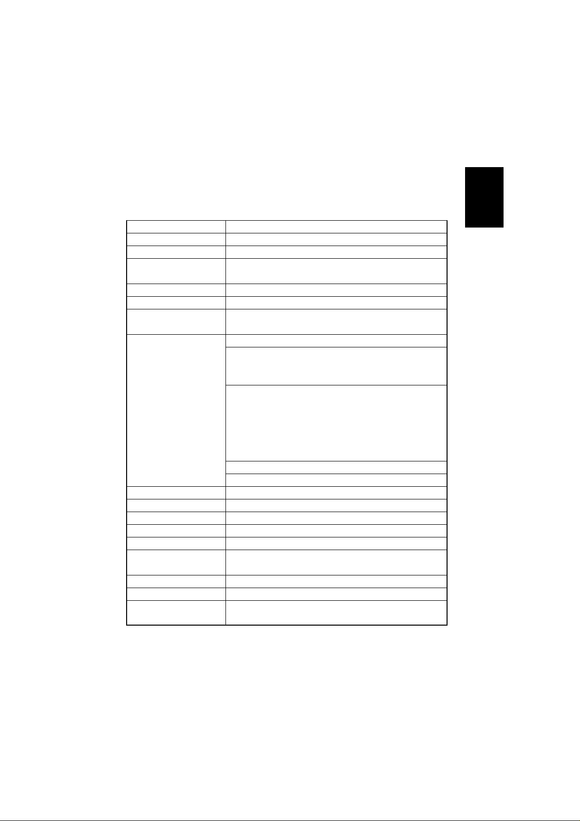
Stapling Position Refer to illustration below (Tolerance : ±2mm)
Stapled Number of copies
Stapled Number of Copies Small size 50 Large size 30
Staple Mounting Staple cartridge (5,000 staples)
Staples Exclusive staples (FQ-SS75)
Staple Detecting Sensor
No
Mounted Manual Stapling
Stapling position
Rear one-point stapling Front diagonal stapling Rear diagonal stapling
5±2mm
6±2mm
Two point stapling
A3, A4 B4, B5 LDR, LTR
5±2mm
82.7±4mm
202.7±4mm
1-2
4.4±2mm
5±2mm
30˚
62.7±4mm
4.5±2mm
182.7±4mm
5±2mm
6±2mm
73.7±4mm
193.7±4mm
30˚
4±2mm
Fig. 1-01

1.2 Features
(1) Large Capacity
A maximum of 1,500 copies can be stacked in normal 3 bins (20Ibs/80g/m
size paper, not stapled).
(2) Improved Paper Transport Performance
Copy paper 12-32Ibs/50-128g/m
(3) Job Offset
The first or the last copy of each job can be discharged to the foreground position,
so that copies in a tray can be sorted.
(4) Four Auto Staple Modes
Stapling position can be selected from 4 modes (one point on rear side, diagonal
stapling on front side, diagonal stapling on rear side, two-point stapling).
(5) Buffer Roller
Buffer roller allows continuous operation of the copier during stapler or offset
operation. (Small size only)
(6) Interruption
The tray for interruption copies can receive up to 50 copies (20Ibs/80g/m
2
can be used.
2
small
2
).
Introduction
1-3
1.3 Exterior Parts
Front lower cover
Tray
P.C.B. cover
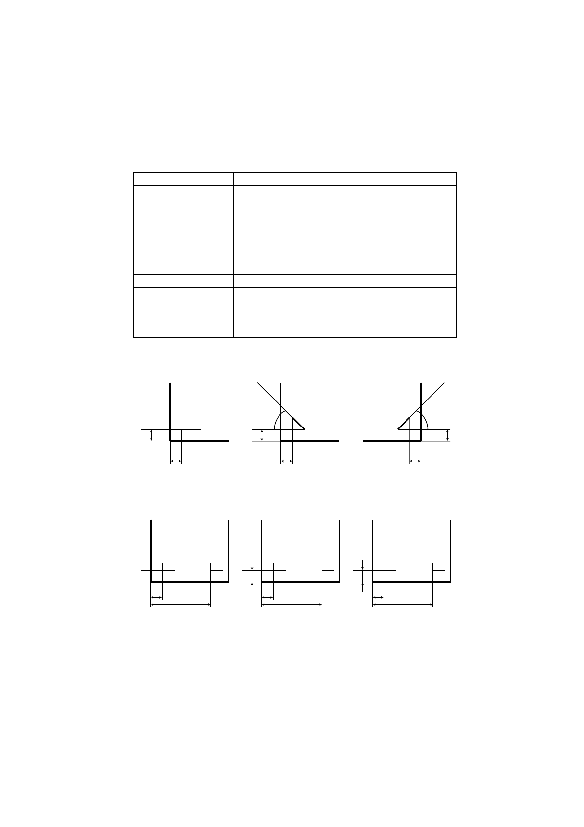
1.4 Structural Drawing
(1) Finisher
Range sensor
Transport roller
Swing guide
Paper exit roller
Interrupt tray
Rear cover
Rear lower cover
Fig. 1-02
Interruption tray
Rolling flapper
Buffer roller
Interruption flapper
Buffer inlet flapper
Tray1/2/3
Shutter
Knurling belt
Tray movement
motor
1-4
Transport roller 1
Longitudinal path
Stapler
Fig. 1-03
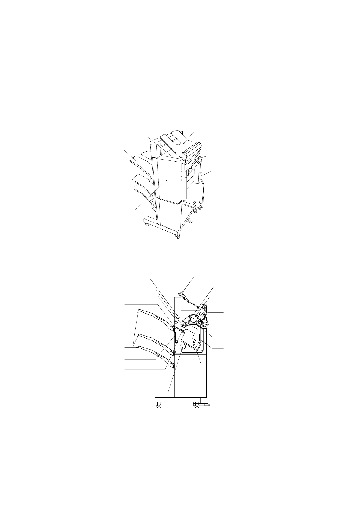
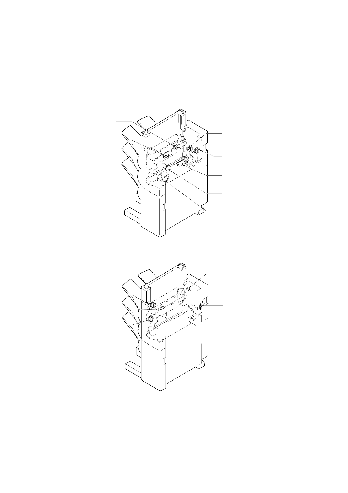
1.5 Component Location
1. Sensor
Height sensor
(PS1)
Buffer path paper
sensor (PI14)
Tray 1 paper
sensor (PI11)
Tamper guide
home position
sensor (PI6)
Door open
sensor (PI16)
Tray 2 paper
sensor (PI12)
Paper exit
sensor (PI3)
Stapler home
position sensor
(PI7)
Tray 3 paper
sensor (PI13)
Shutter open
sensor (PI5)
2. Switch
Door switch
(MS1)
Shutter close
detecting
switch (MS4)
Staple
detecting
switch (MS8)
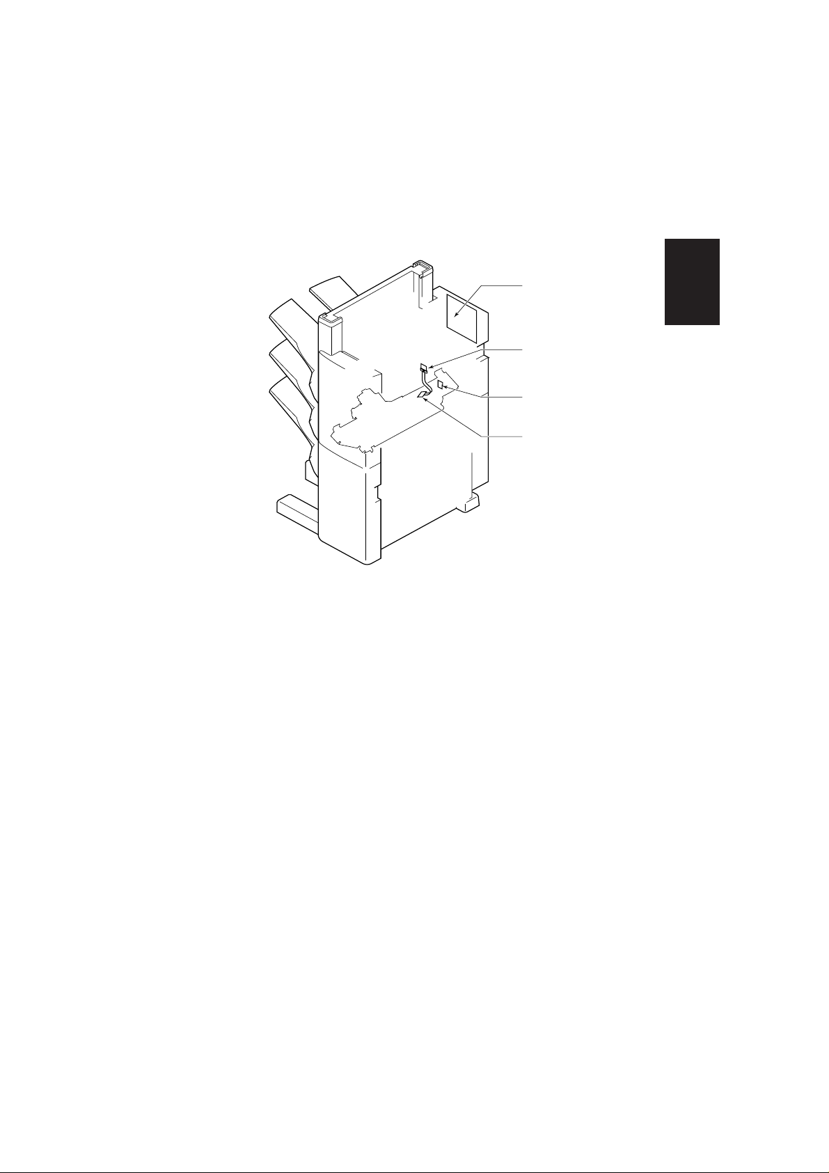
Buffer path entrance
paper sensor (PI17)
Swing guide open
sensor (PI18)
Entrance sensor (PI1)
Staple tray sensor
(PI4)
Joint sensor (PI15)
Tray shift motor clock
sensor 2 (PI19)
Tray shift motor
clock sensor 1 (PI9)
Tray home position
sensor (PI8)
Paper exit motor
clock sensor (PI10)
Fig. 1-04
Tray upper limit
detecting switch (MS5)
Swing guide close
detecting switch 1 (MS2)
Safety area switch
(MS3)
Swing guide close
detecting switch 2 (MS6)
Tray shift motor
thermo-switch (TS1)
Staple home position
switch (PI21)
Cartridge switch (MS7)
Introduction
Fig. 1-05
1-5
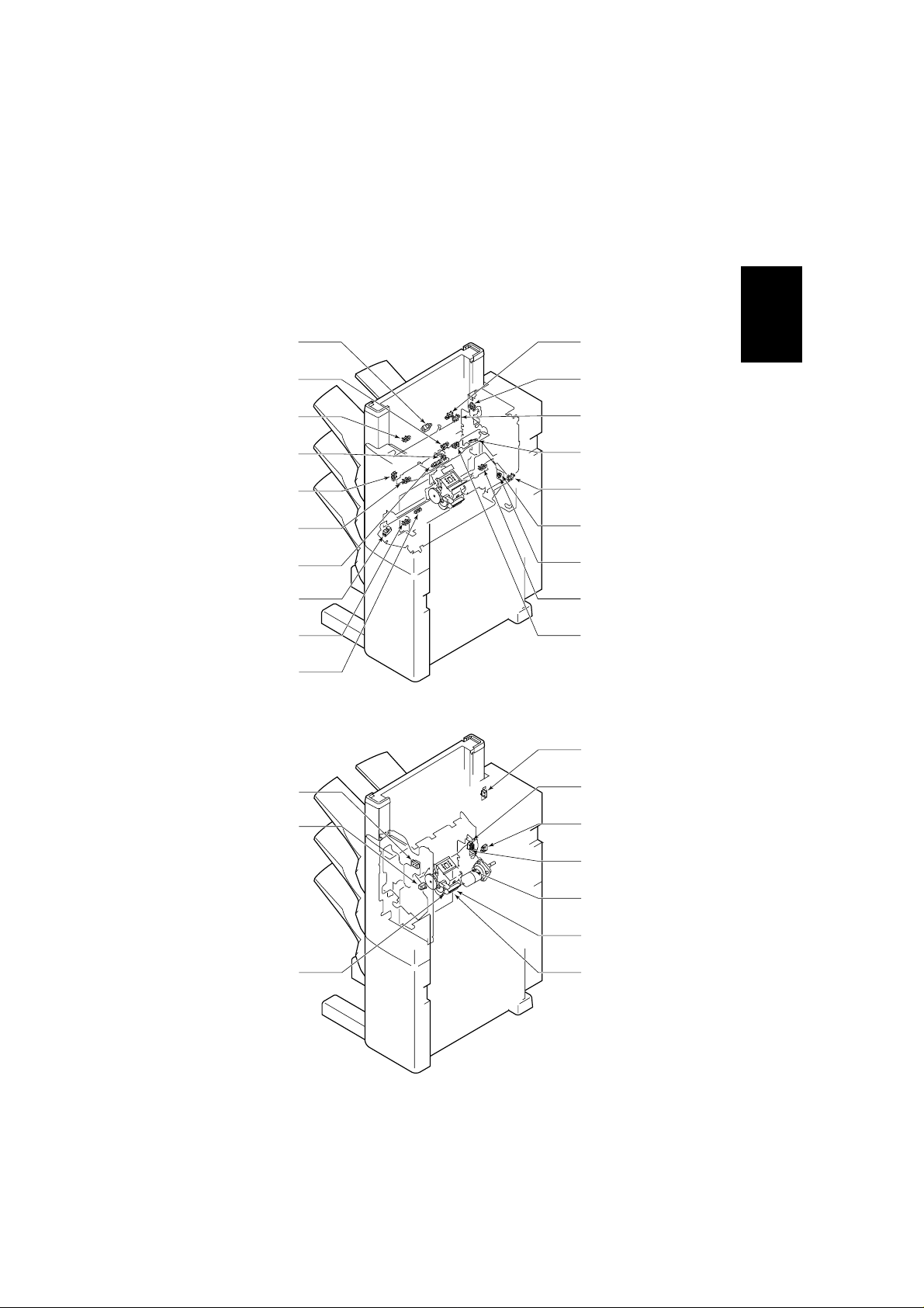
3. Motor
Paper exit
motor (M2)
Tamper motor
(M3)
4. Solenoid
Transport motor 2
(FA-F355 only)
(M8)
Transport motor 1
(M1)
Tray shift motor
(M5)
Stapler shift motor
(M4)
Staple motor (M6)
Fig. 1-06
Interruption
solenoid (SL4)
Paddle
solenoid (SL5)
Buffer exit
solenoid (SL3)
Shunting
solenoid (SL6)
1-6
Buffer entrance
solenoid (SL2)
Fig. 1-07
5. PCB
Finisher controller
PCB
Introduction
Relay PCB 4
Sensor PCB
Relay PCB 3
Fig. 1-08
1-7
Section II Operation
2.1 Outline
This finisher receives commands from the copier and discharges into the tray the
papers sent from the copier in normal mode, shift mode or staple mode.
If the command to discharge into interruption copy bin is sent from the copier, it will
operate accordingly.
There are four paper exit modes.
Paper exit mode Normal exit Simple loading
Job offset
Stapling Front diagonal stapling
Rear one-point stapling
Rear diagonal stapling
Interruption
copy exit
Simple loading
Two-point stapling
Fig. 2-01
Operation
2.1.1 Normal Exit
(1) Nomal mode
The paper is sent into the exit tray face up.
Paper exit tray
Paper
Transport roller 2
Paper exit roller
Fig. 2-02
Transport roller 1
Fig. 2-03
2-1
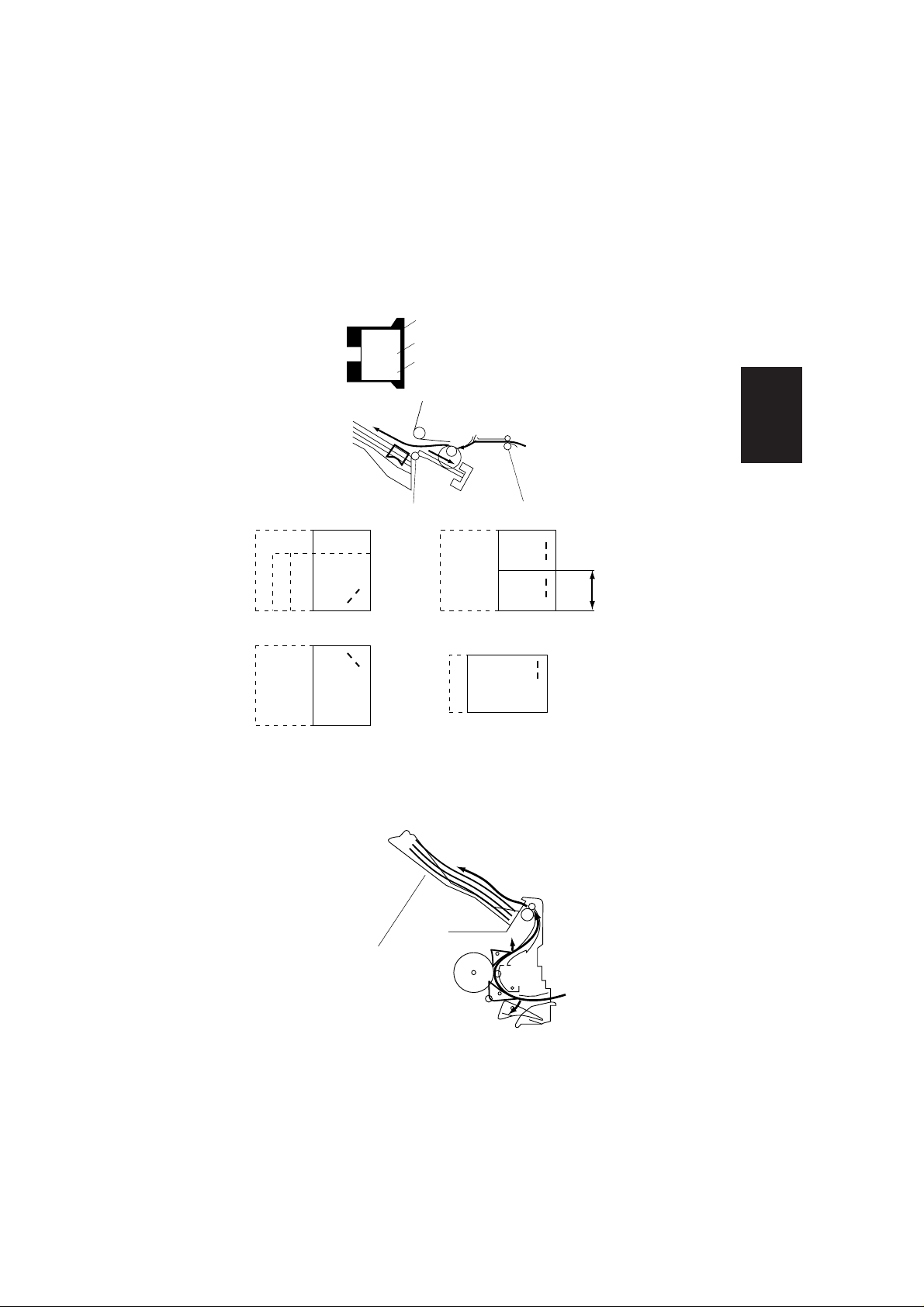
(2) Job Offset Mode
The first or the last paper of each sort, is discharged into the staple tray faceup, shifted by 30mm.
Whether the first paper should be shifted or the last one should be shifted
depends on the command from the copier.
The second paper or the first paper of the next sort, is not discharged into the
staple tray but to the tray.
The first paper or the last paper of each sort
Swing guide
Staple
tray
Paper exit roller Transport roller 1
Stopper
Fig. 2-04
The second paper or the papers following the first paper of the next sort
tray
Second paper or first paper of the next sort
First paper or last paper of each sort
Swing guide
Staple
tray
Stopper
Transport roller 1
Paper exit roller
Fig. 2-05
2-2
(3) Staple mode
The paper is loading in the staple tray. Next the first item into the tray.
tray
Paper
Staple
Swing guide
Operation
Staple
tray
Paper exit roller
Stopper
Transport roller 1
Width of paper
Front diagonal stapling 2-point stapling
Rear diagonal stapling Rear 1-point stapling
2.1.2 Interruption copy exit
When the paper enters the finisher, they are guided by the reversing plate and
discharged into the bin.
Interruption tray
Fig. 2-06
Fig. 2-07
Interruption tray
Fig. 2-08
2-3
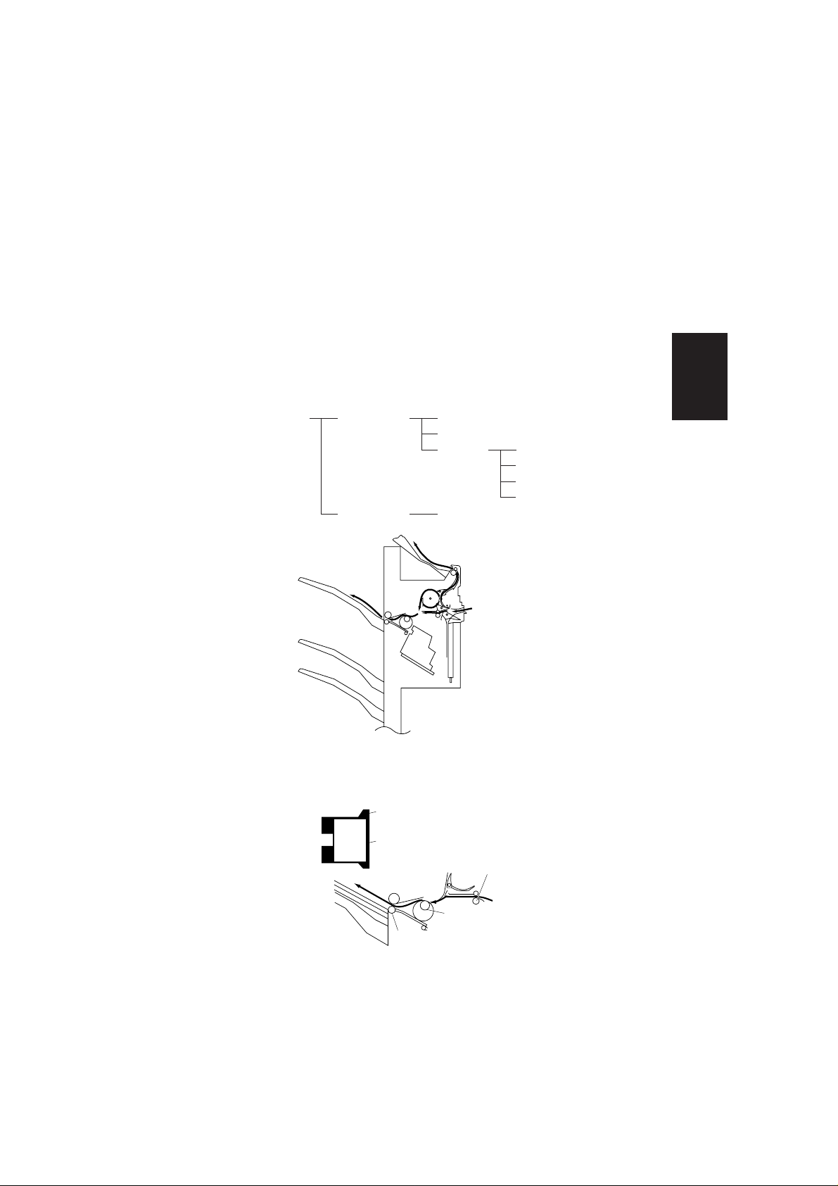
2.1.3 Exit route
There are three normal exit routes. The route that is used depends on the
paper size and discharge mode.
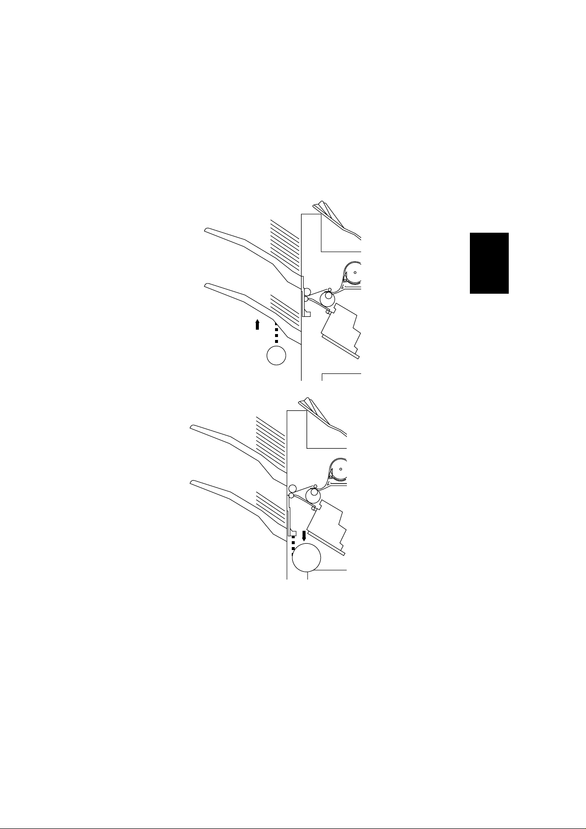
(1) Route for small size
When small size paper is loaded normally, the paper passes under the buffer
roller.
Paper exit roller
Buffer roller
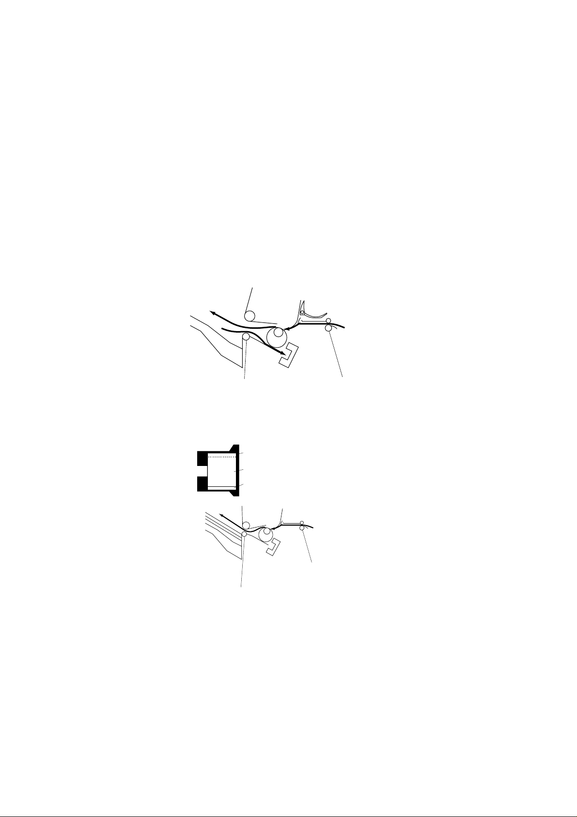
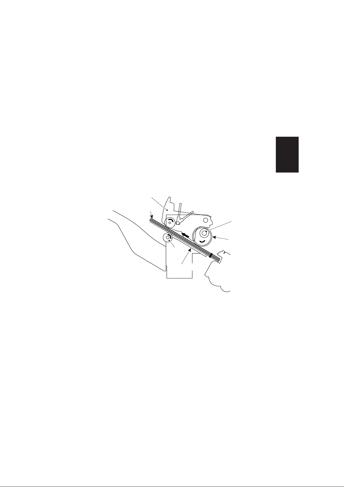
(2) Route for large size
When large size paper is loaded or the paper is loaded in R direction, the paper
passes above the buffer roller.
This has an effect of expanding the distance between papers.
Buffer roller
Fig. 2-09
2-4
Transport roller 2
Paper exit roller
Fig. 2-10
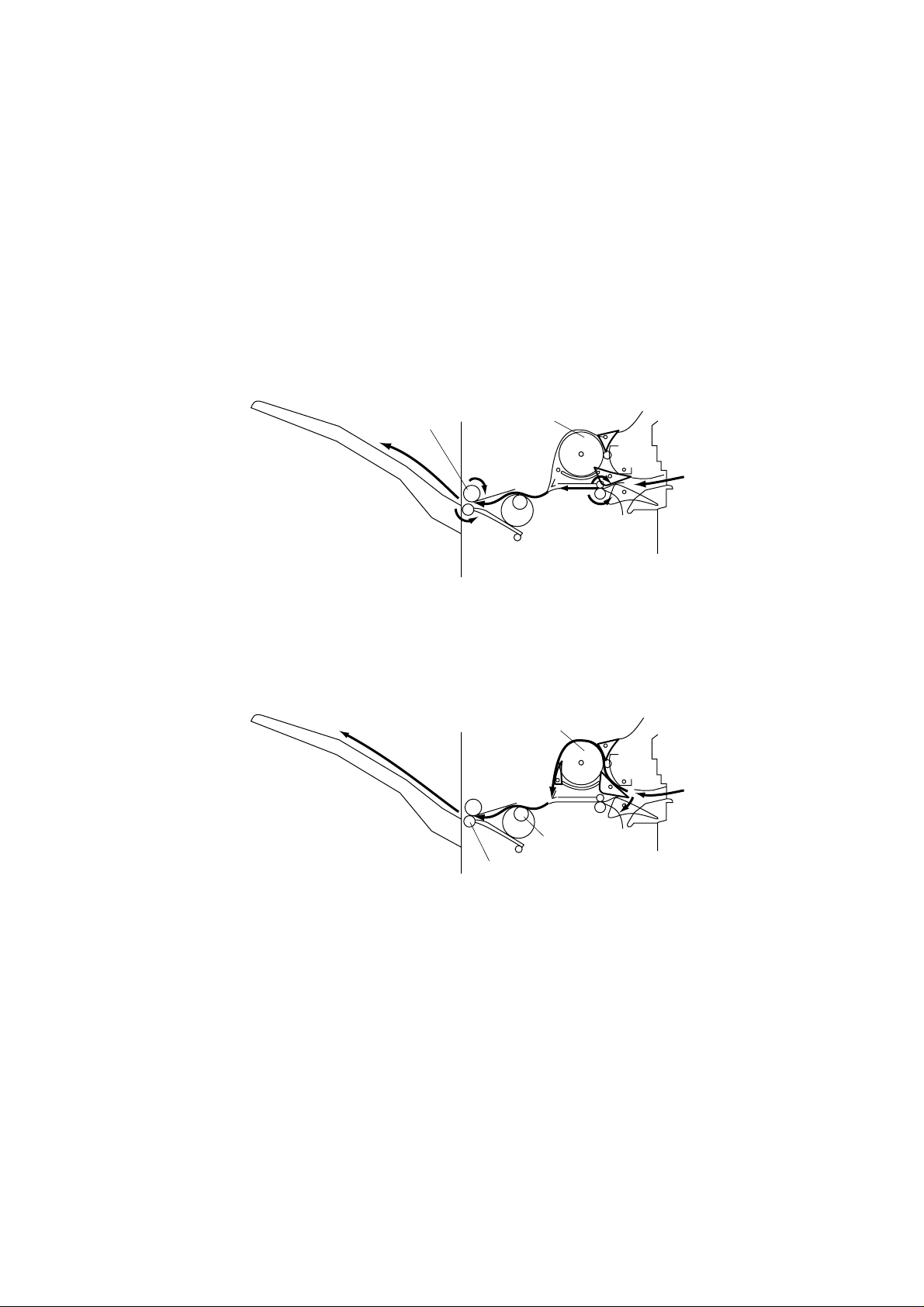
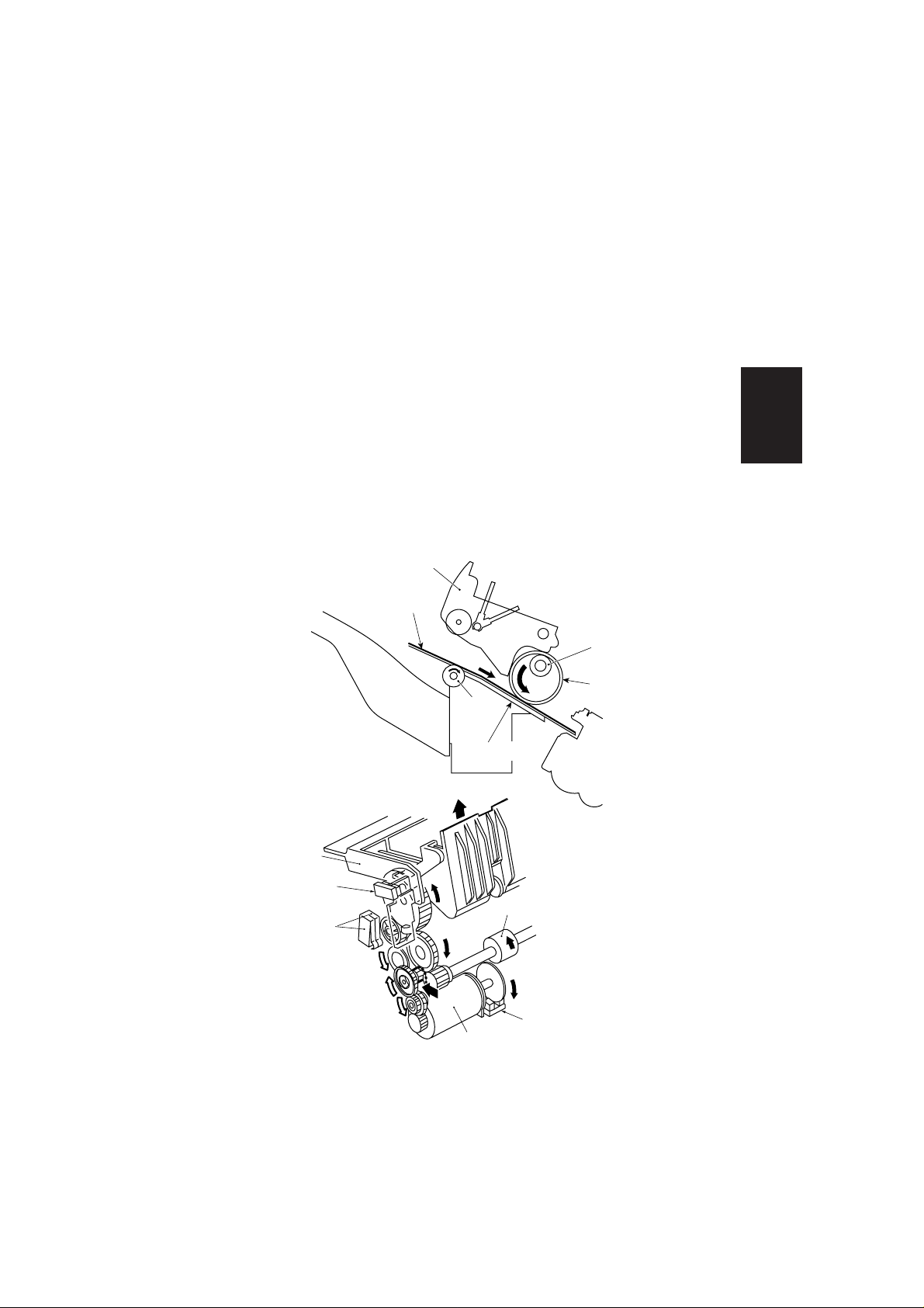
(3) Buffer route
Paper takes this route when small size paper is used in the job offset or staple
mode.
Offset paper or the first and the second sheet of paper which follows the final
paper to be stapled takes this route.
a) The first sheet of paper is transported toward the buffer roller.
buffer roller
Fig. 2-11
b) When the first sheet of paper is rolled around the buffer roller, the second
sheet of paper is transported from the copier.
Operation
Fig. 2-12
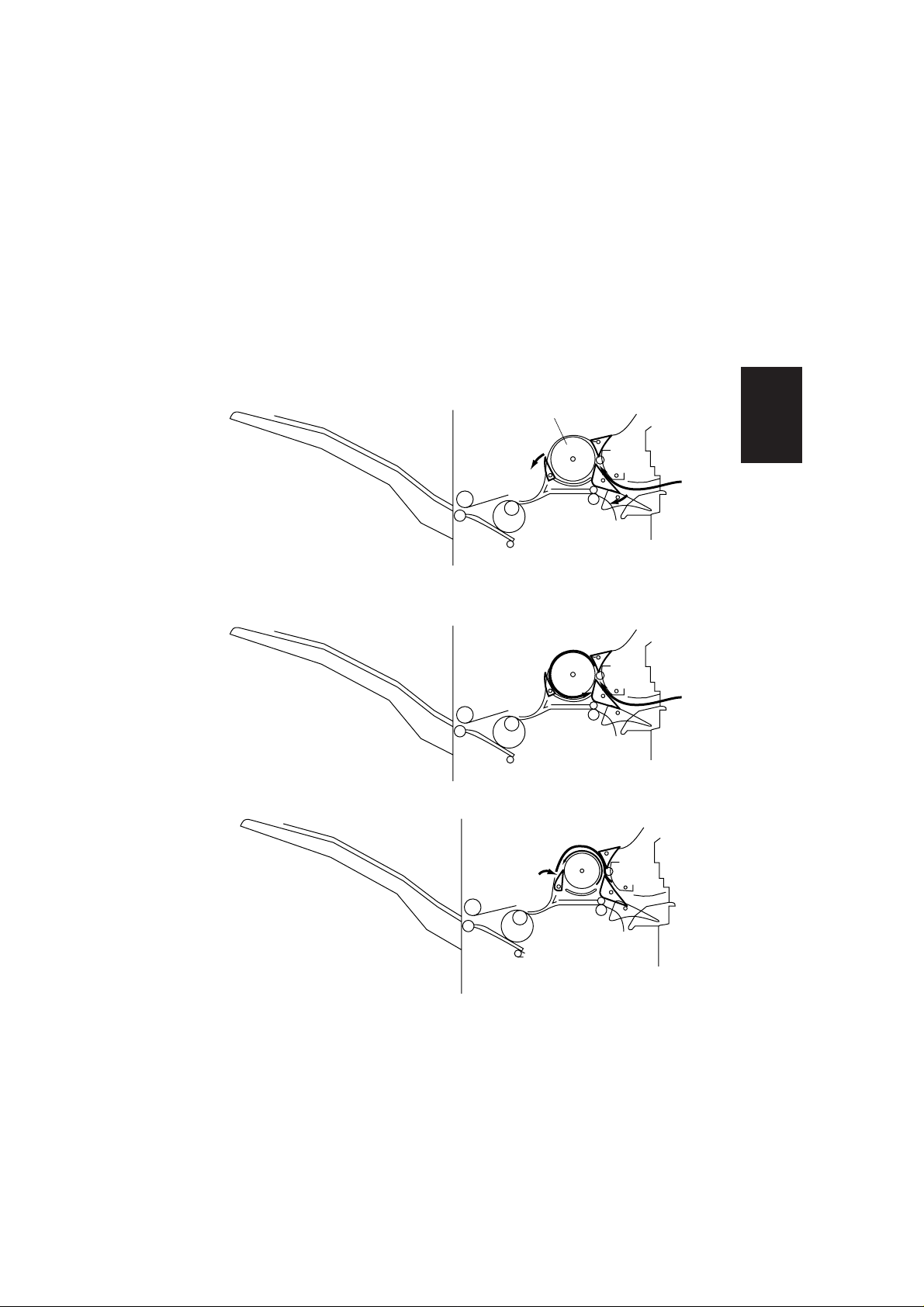
c) The second sheet of paper lies on the first sheet of paper.
Fig. 2-13
d) The first and the second sheets of paper are discharged into the tray or
pulled inside the staple tray at the same time.
2-5

2.2 Mechanism
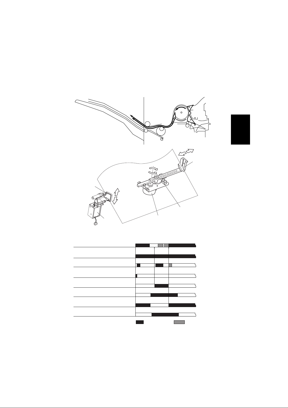
2.2.1 Job offset
The job offset operation, the first or last copy of each job is shifted forward, and
the other copies of that job are exited in the normal position.
Papers are moved by the tamper.
Tamper home position detecting sensor (PI6) checks whether or not the tamper
is on the home position.
When the switch is turned on, the finisher controller P.C.B. drives the tamper
motor to return the tamper to the home position.
Finisher controller P.C.B. stops paper exit motor (M3) at the moment the rear
end of the paper comes out of the transport roller 2.
Then the finisher controller P.C.B. reverses the rotation of paper exit motor,
and the paper exit motor gear is shifted to drive position.
In response, the drive of paper exit motor is transmitted to swing guide, pushing
up the guide.
When the swing guide open detecting sensor (PI18) detects the swing guide,
paper exit motor stops, and swing guide stays elevated.
When swing guide is shifted up, papers are transported to the staple tray by
rollet belt attached to the transport roller.
Papers transported to the staple tray are detected by staple tray paper detecting
sensor (PI4).
The finisher controller P.C.B. drives tamper motor (M3) and adjusts the position
of tamper to the point approximately 7mm from the rear end of the paper.
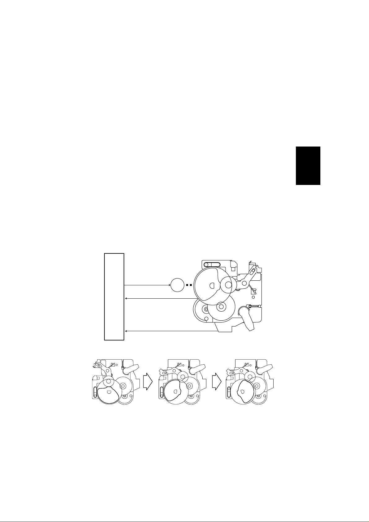
When the paper is received by the staple tray, guide plate shunting solenoid
(SL6) shunts the guide plate and places under the staple tray.
Then the tamper motor shifts papers forward by 30mm.
After shifting the paper, finisher controller P.C.B. reverses the rotation of tamper
motor, and shifts the tamper to the position 7mm from the rear end of papers.
Then the finisher controller P.C.B. reverses the rotation of paper exit motor
again, and lowers swing guide.
When the swing guide is lowered and swing guide open/close detecting switch
2 (MS6) is turned on, paper exit motor rotates normally, causing normal rotation
of the paper exit roller, and consequent discharge of papers into the tray.
After the paper is discharged, the guide plate returns to the elevated position.
2-6
Guide plate
Shunting
solenoid
(SL6)
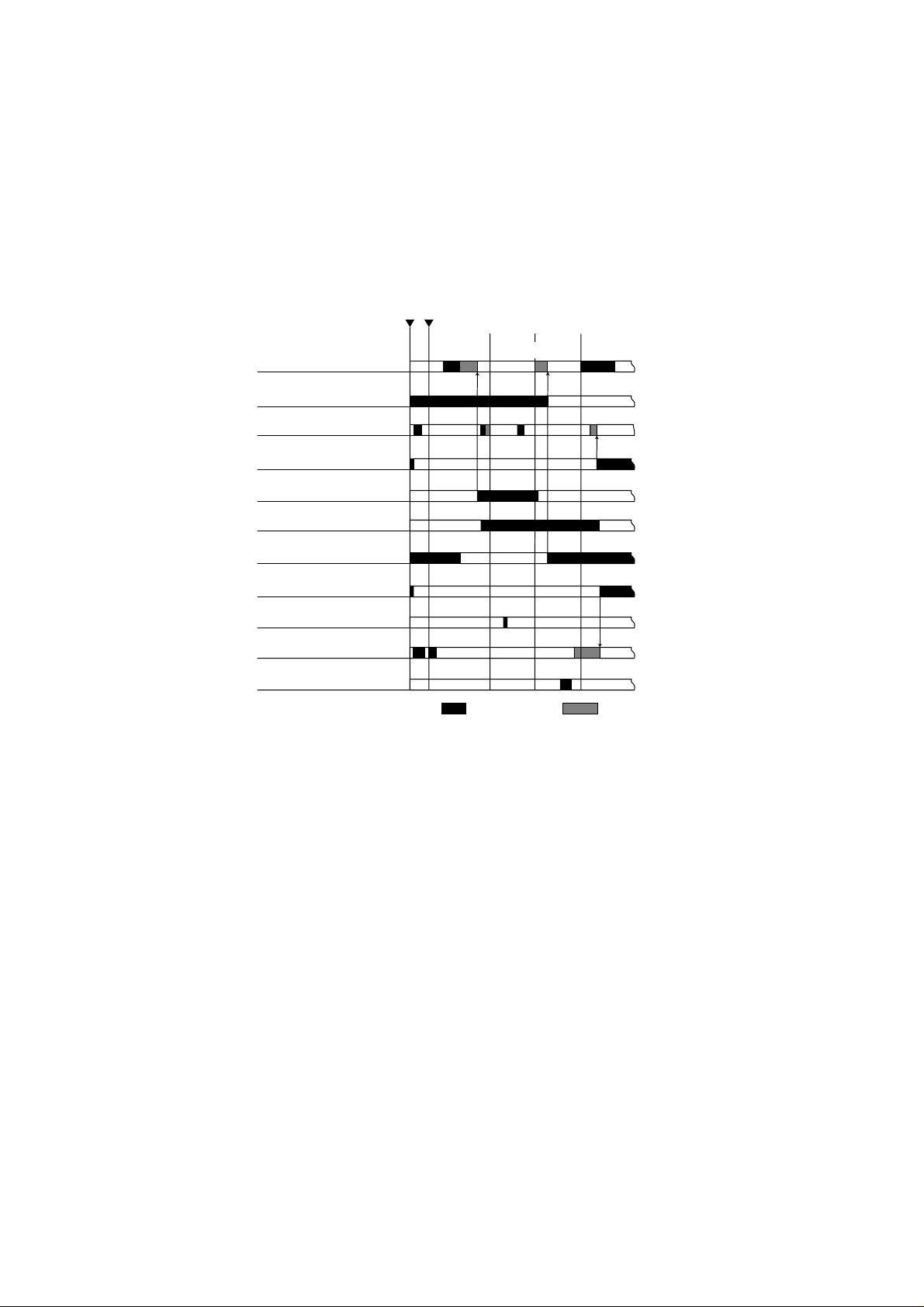
Job offset sequence
Paper exit motor (M2)
Transport motor 1,2 (M1/M8)
Tamper motor (M3)
Tamper home position
sensor (PI6)
Swing guide open detecting
sensor (PI18)
Paper
Fig. 2-14
Operation
Tamper
Tamper guide
Position sensor (PI6)
Tamper motor (M3)
Fig. 2-15
Staple tray paper sensor (PI4)
Swing guide open/close
detecting switch (MS2)
Guide plate shunting solenoid
(SL6)
*Transport motor 2 : FA-F355 only
Fig. 2-16
Normal
::
rotation
Reversed
rotation
2-7

2.2.2 Stapling
(1) Outline
Copies can be stapled by the stapler unit when staple mode is selected.
The stapling position is decided by the selected staple mode and paper size.
The stapler shifting/home-position sensor (PI7) detects whether or not the stapler
unit is in the home position.
When the switch is turned on, the finisher driver P.C.B. drives the stapler shifting
motor (M4) to return the stapler unit to the home position.
If the stapler unit is in the home position, it will stay there.
Width of paper /2
Front diagonal stapling 2-point stapling
Rear diagonal stapling Rear 1-point stapling
Fig. 2-17
2-8
Paper
Stapler shift home
position sensor (PI7)
Stapler shift motor (M4)
Stapler
Fig. 2-18
(2) The first paper
When the rear end of the first paper rolls out of transport roller 2, the finisher
controller P.C.B. stops the paper exit motor (M2).
Then the rotation of the paper exit motor is reversed, and the gear is shifted to
the swing guide drive.
The paper exit motor shifts the swing guide up until it is detected by the swing
guide detecting sensor (PI18).
When the swing guide opens, the paper is transported by the rollet belt, (attached
to transport roller 2) to staple tray.
The paper is detected by the staple tray paper detecting sensor (PI4).
After the staple tray paper detecting sensor detects paper, the finisher controller
P.C.B. drives the tamper shifting motor (M3) to tap the paper.
The tamper is positioned 10mm from the end of paper.
The swing guide stays elevated until the last paper is loaded on the staple tray.
Swing guide
First paper
Transport roller 2
Rollet belt
Tray 1/2
Paper
exit
roller
Staple tray
Stapler
Fig. 2-19
Operation
Swing guide
Swing guide open
sensor (PI18)
Swing guide close
detecting switch
(MS2/MS6)
Paper exit motor
Fig. 2-20
Paper exit motor clock
sensor (PI10)
Paper exit motor (M2)
2-9
(3) The second and the proceeding papers
When the tail edge of the second and the proceeding paper roll out of transport
roller 2, the finisher controller P.C.B. turns the paddle solenoid (SL5) on.
Then the transport motor's (M1) drive rotates the paddle.
Papers pushed by the paddle are transported to staple tray.
Paddle operates twice for each B4, A3, LDR and LGL, and once for the other
sizes.
When paper is loaded into the staple tray, the finisher controller drives the
tamper shifting motor (M3) and taps the paper.
Swing guide
Paddle
2nd and following papers
Transport roller 2
Rollet belt
Tray 1/2
Paper
exit
roller
Staple tray
Stapler
Fig. 2-21
Paddle solenoid (SL5)
* Transport motor 2 : FA-F355only
2-10
M1
or
M8
Paddle
Paddle
2nd and following
papers
Stapler
StopperTransport motor 1 or 2
1st paper
Fig. 2-22
(4) The last paper
After the last sheet of paper is finished being tapped, the finisher controller
P.C.B. shifts the tamper to the tapping position (holding paper with tamper),
then stops the tamper motor (M3).
Then the finisher controller P.C.B. reverses the rotation of the paper exit motor
(M2) again, and lowers the swing guide.
The finisher controller P.C.B. shifts the stapler and carries out stapling according
to the staple mode (P2-19, Illustration 2-2-12) set on the copier.
After stapling is finished, the finisher controller P.C.B. drives the tamper motor
and shifts the tamper to the point 10mm from the rear end of paper.
Then normal rotation of the paper exit motor (M2) occurs to discharge stapled
paper into the tray.
Swing guide
paper
Transport roller 2
Rollet belt
Tray 1/2
Paper
exit
roller
Staple tray
Stapler
Operation
Fig. 2-23
(5) Stapler unit shift control
The stapler unit is moved by the stapler shift motor (M4).
Home position is detected by the stapler shift/home position sensor (PI7).
When the signal is sent from the copier, the stapler moves to the center of its
shift range.
This movement occurs in every mode, because the selected mode is not yet
been detected.
When the first sheet of paper reaches the registration sensor of the copier, the
staple mode is signalled from the copier and the unit moves to the appropriate
position depending on stapling point and paper size.
2-11

Stapler modes and home position:
a) Front diagonal stapling
Home position is the stapling point in this mode.
Stopper
Staple tray direction
Stopper
Guide
Stapler
Fig. 2-24
b) Rear one-point stapling
The stapler moves back and forth between the center position and the stapling
point.
Stopper
Stapling point
2-12
Staple tray direction
Guide
Stopper
Home position
Stapler
Fig. 2-25
c) Rear diagonal stapling
When LTR or B5 is used, home position is in the back of the stapling point
Stapler moves back and forth between home position and stapling point.
Stapler
Home position
Stapling point
Stopper
Staple tray direction
Stopper
Operation
Guide
Fig. 2-26
d) Two-point stapling
The home position is the center of paper. The stapling starts from the rear
side.
Stopper
Stapling point
Home position
Staple tray direction
Stapler
Stapling point
Stopper
Guide
Fig. 2-27
2-13
Rear one-point stapling of 2 papers
Starting signal Mode detection
Loaded paper
Paper exit motor (M2)
1st paper
Transport motor 1 (M1)
Transport motor 2 (M8)
Tamper motor (M3)
Tamper home position
sensor (PI6)
Swing guide open
detecting sensor (PI18)
Staple tray paper
sensor (PI4)
Swing guide open/close
detecting switch (MS2)
Stapler home position
sensor (PI7)
Paddle solenoid (SL5)
Stapler shift motor (M4)
2nd
Staple Paper exit
paper
2-14
Stapler motor (M4)
* Transport motor 2 : FA-F355 only
Fig. 2-28
Normal
::
rotation
Reversed
rotation
(6) Stapler unit
Stapling is carried out by the staple motor (M6). One staple is made every time
the cam is rotated by the motor.
The cam home position is detected when the staple movement home position
detecting sensor (PI2) is turned ON.
Normal rotation and reversed rotation of the staple motor is controlled by micro
computer (Q1) on finisher controller P.C.B..
When the staple movement home position detecting sensor is OFF, the finisher
controller P.C.B. revolves staple motor in reversed direction until the sensor is
turned ON, returning staple cam to the initial condition.
The staples inside staple cartridge are detected by staple switch (MS9).
Finisher controller P.C.B. drives staple motor (M6) only when swing guide close
detecting switch 2 (MS6) is ON (swing guide is closed).
This is to ensure safety in case fingers are put inside the stapler.
Finisher controller P.C.B.
Operation
Staple motor
drive signal
M6
Staple home
position detecting signal
Satapler detecting signal
Fig. 2-29
Fig. 2-30
2-15

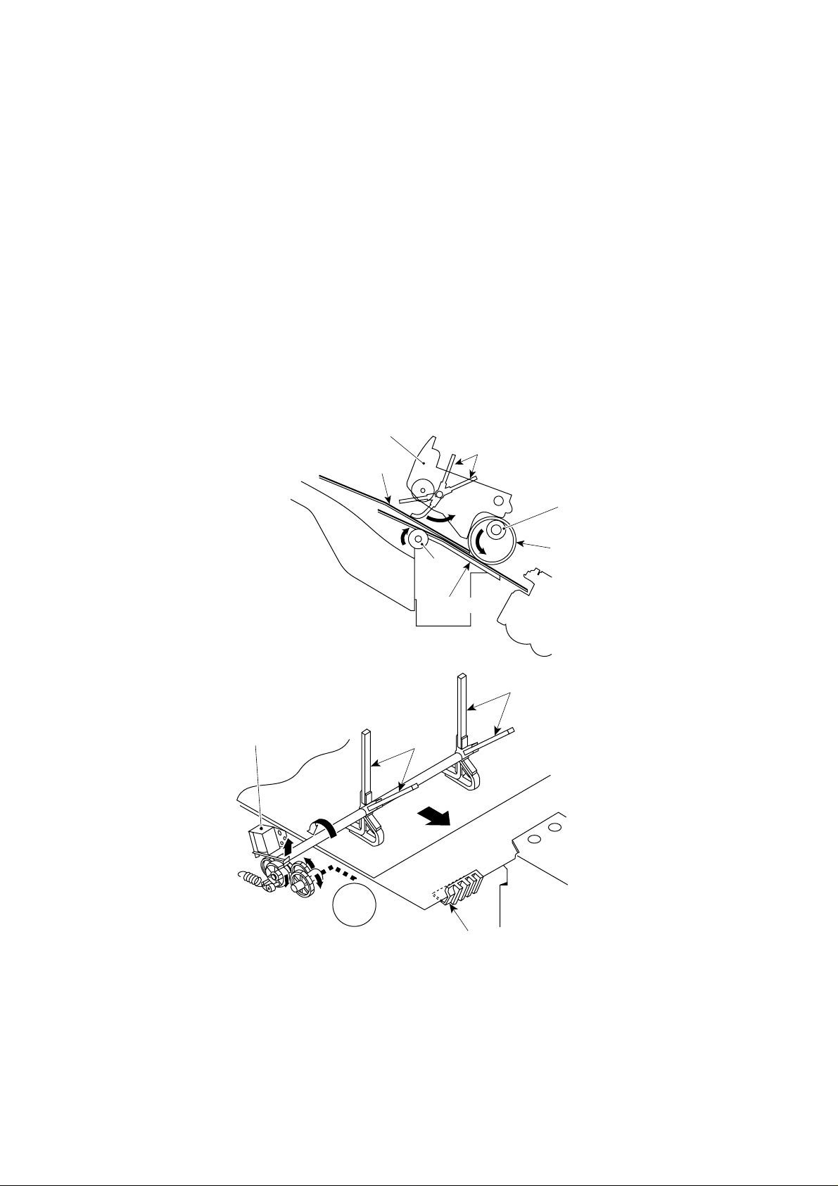
2.2.3 Tray Operation
(1) Outline
There are three paper exit trays used for normal feed.
Vertical movement of trays is carried out by the drive of the vertical shift motor
(M5). Clock pulses from the tray vertical movement motor clock sensors 1 and
2 (PI19/PI9) detect the tray position after the home position detecting sensor
(PI8) is activated.
Tray shift motor thermo switch (TP1) is attached to the tray vertical shift motor
(M5).
When the sensor temperature reaches approximately 73.5°C after continued
movement of the motor, the sensor is turned ON and the finisher controller
P.C.B. shuts off the load to the motor.
When the sensor temperature cools down to approximately 40°C, the sensor
is turned OFF and the finisher controller P.C.B. resumes, the loading on the
motor.
When the power supply switch is turned on, the tray is returned to home position
by the tray vertical shift motor (M5) which is driven by the finisher controller
P.C.B.
When the tray is in home position, it will stay there.
The finisher controller P.C.B. moves the trays up and down to place the selected
tray in the paper exit position.
2-16
The upper limit of the tray is detected by the tray upper limit detecting switch
(MS5).
When the tray upper limit detecting switch is ON, the finisher controller P.C.B.
stops the drive of the tray shift motor (M5).
The height of papers discharged into the tray is detected by height sensor
(PS1). The sensor measures the distance between the upper half of the paper
stack and the paper exit. If the distance becomes less the prescribed value,
the tray is lowered.
When the safety area detecting switch (MS3) is turned ON while the shutter or
swing guide is open, the finisher controller P.C.B. stops movement of finisher
by shutting off the +24V power supplied to tray shift motor (M5).
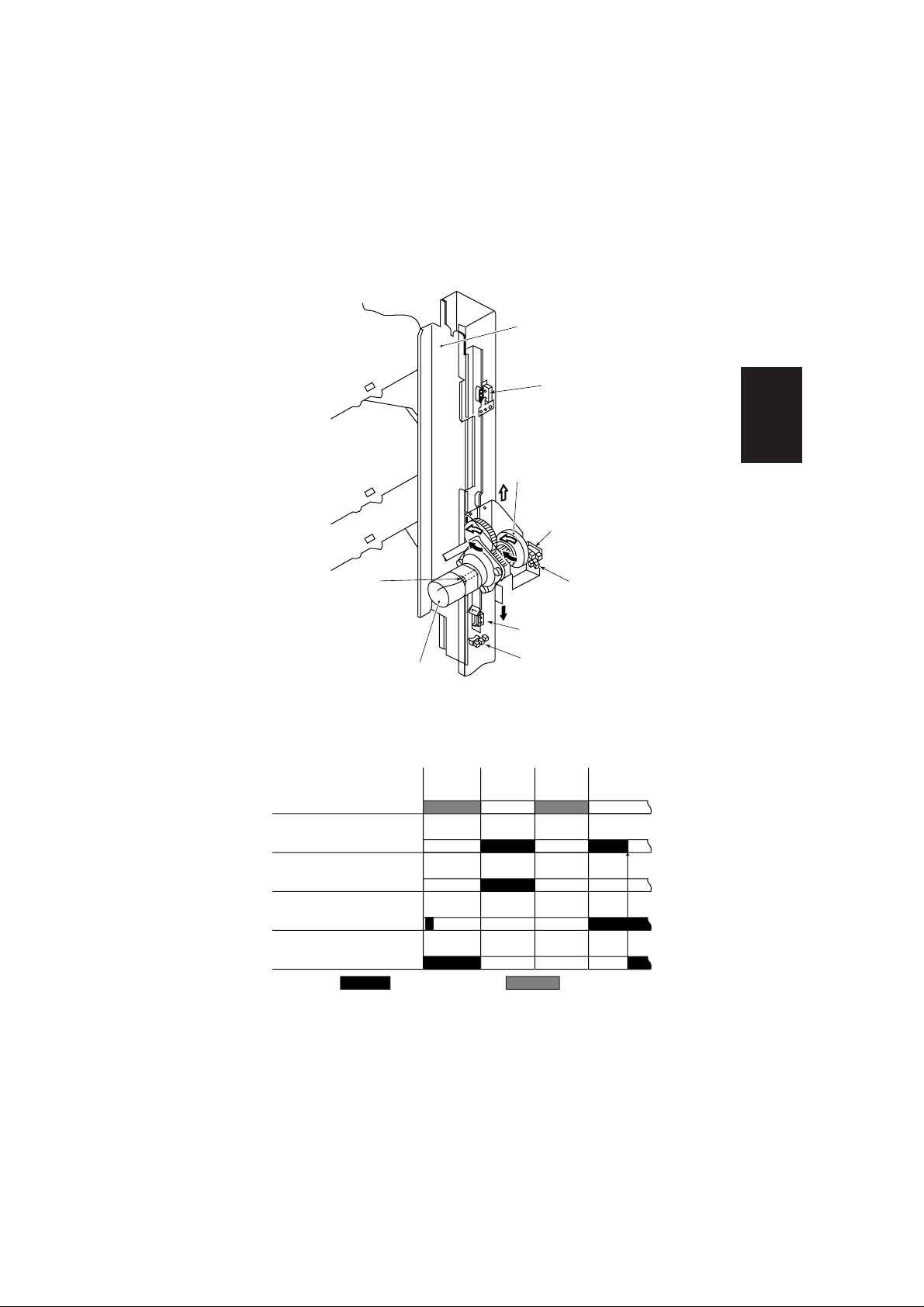
Tray 1
Tray 2
Tray 3
Tray guide
Tray upper limit detecting
switch (MS5)
Operation
Encoder
Tray shift motor clock
detecting sensor 1 (PI9)
Tray shift motor thermoswitch (TP1)
Tray shift motor (M5)
Shift from Tray 1 to Tray 2
Transport motor (M1)
Tray shift motor (M5)
Shutter close sensor
Shutter open detecting
switch (MS4)
Height sensor (PS1)
Tray shift motor clock
detecting sensor 2 (PI19)
Safety area switch (MS3)
Tray home position sensor
Shutter
close
Tray
shift
(PI8)
Shutter
open
Tray
shift
Fig. 2-31
(PI6)
Detecting of
appropriate height
: Normal rotation : Reversed rotation
Fig. 2-32
2-17

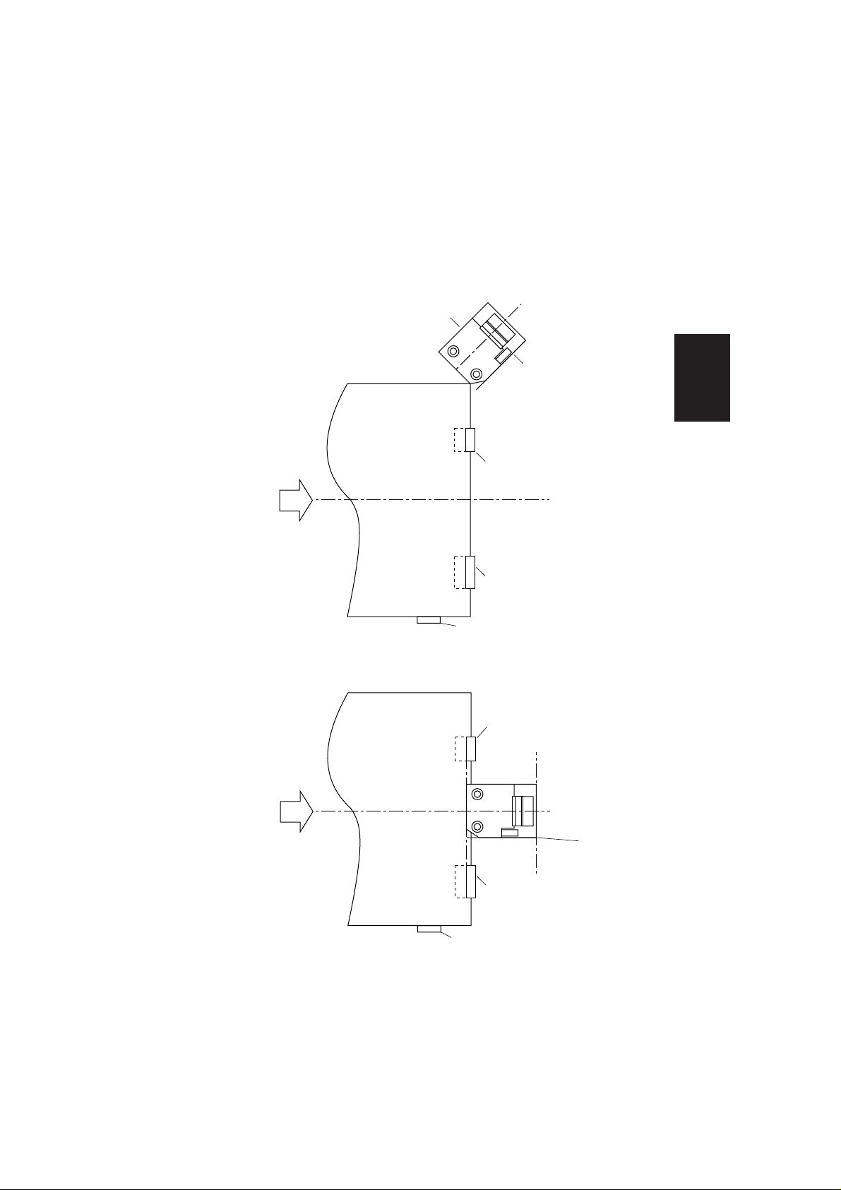
(2) Shutter Operation
Before changing, by tray shift motor (M5) operation, the trays for receiving
papers, the finisher controller P.C.B. closes the shutter on paper exit.
This prevents jamming of papers loaded on tray at paper exit.
The shutter moves upward (closes) when the transport motor 1 or 2 rotates in
reverse, and stays in that position when the motor stops.
Next time the motor rotates in reverse, the shutter moves downward (opens,
paper exit possible).
When the shutter stays in the elevated position, claws extended from the swing
guide engage with the back face of shutter.
This prevents the swing guide from opening due to friction between loaded
paper and swing guide at the time of tray shifting.
The claws are withdrawn and disengaged when the shutter is lowered.
Upward movement of the shutter is detected by the shutter open sensor (PI5).
Downward movement of the shutter is detected by the close detecting sensor
(MS4).
The process is shown below:
a) Transport motor 1 or 2 rotates in reverse and the shutter moves upward.
2-18
* Transport motor 2 : FA-F355 only
M1
or
Transport motor 1 or 2
M8
Fig. 2-33
b) Tray shift motor rotates and shifts the new tray to the lowest loading point.
Tray shifting distance is detected by the tray shift motor clock sensor 1,2
(PI19,9).
M5
Tray shift motor
c) Transport motor 1 or 2 rotates in reverse and shutter moves downward.
Fig. 2-34
Operation
* Transport motor 2 : FA-F355 only
M1
or
Transport motor 1 or 2
M8
Fig. 2-35
2-19

d) Tray shift motor rotates and adjusts the tray to the height of loaded papers.
Appropriate height is detected by height sensor (PS1).
Height sensor (PS1)
M5
Tray shift motor
Transport motor
M1
Shutter open
switch (MS4)
Shutter close
sensor (PI5)
Claw
Shutter
Claw
Fig. 2-36
Shutter drive sequence
Shift from Tray 1 to Tray 2
Transport motor 1or 2
Tray shift motor (M5)
Shutter close sensor (PI6)
Shutter open
detecting switch (MS4)
Height sensor (PS1)
* Transport motor 2 : FA-F355 only
2-20
One-way cam
(M1/M8)
Shutter
close
Tray
shift
Shutter
open
Tray
shift
Detecting of appropriate height
: Normal rotation : Reversed rotation
Fig. 2-37
Fig. 2-38
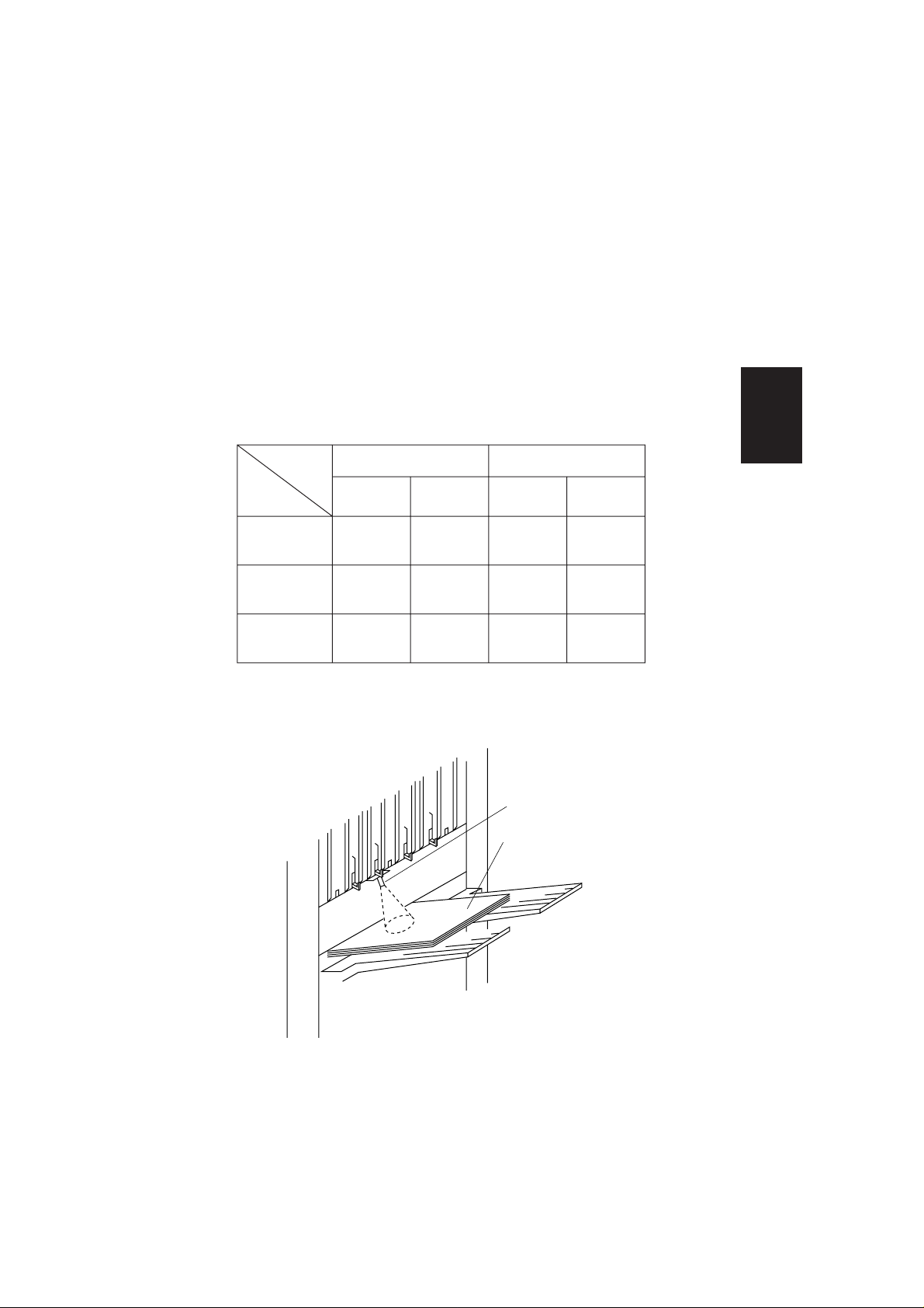
(3) Detection of tray-loaded paper amount
The amount of copies made in the sort mode (stapling or offset number) and
discharged into tray, are memorized by the finisher controller P.C.B..
The height of the paper stack is detected by the height sensor (PS1).
The maximum loading amount in each tray is shown in table 2-01.
When the tray is loading amount shown in table 2-01, the finisher controller
P.C.B. stops operation and sends the signal to the copier that the tray is fully
loaded.
Loading
mode
Non-staple sort
Staple sort
Operation
Tray
Small size
Large size Small size Large size
300 sheets or
Tray 1 300
150
30 sorts
(whichever less)
750 sheets or
Tray 2 1000 500
30 sorts
(whichever less)
200 sheets or
Tray 3 200 100
20 sorts
(whichever less)
Note:
1.Small size : A4, Letter, B5
2.Large size : A3, A4R, B4, Legal, Ledger, Letter R
Height sensor (PS1)
Paper
150 sheets or
30 sorts
(whichever less)
500 sheets or
30 sorts
(whichever less)
100 sheets or
20 sorts
(whichever less)
Table. 2-01
Fig. 2-39
2-21
 Loading...