

Page 1

FA-A888 Back to Model List
Contents
WARNING
I. Introduction
1.1 Specifications.......................................................................................... 1-1
1.2 Features.................................................................................................. 1-2
1.3 Exterior ................................................................................................... 1-3
1.4 Interior..................................................................................................... 1-3
II. Sequence
2.1 Original paper feed system..................................................................... 2-1
2.2 Original paper exit system ...................................................................... 2-5
2.3 Original count system ............................................................................. 2-8
III. Maintenance
3.1 Maintenance chart .................................................................................. 3-1
3.2 Disassembly and Assembly.................................................................... 3-2
3.3 Adjustment.............................................................................................. 3-9
IV. Electrical
4.1 Function of electrical parts...................................................................... 4-1
4.2 Signal information by connectors............................................................ 4-9
4.3 Explanation of circuit............................................................................... 4-13
IntroductionStructureMaintenanceElectrical
Troubleshooting
V. Troubleshooting
5.1 Error detection by self-diagnosis ............................................................ 5-1
(1) User Error ........................................................................................ 5-1
(2) Paper jam......................................................................................... 5-2
(3) ADF function error............................................................................ 5-3
VI. Installation
6.1 Unpacking............................................................................................... 6-1
6.2 Installation procedure ............................................................................. 6-2
Installation
Page 2

WARNING
This service information is designed for experienced repair technicians only and
is not designed for use by the general public.
It does not contain warnings or cautions to advise non-technical individuals of
potential dangers in attempting to service a product.
Products powered by electricity should be serviced or repaired only by experienced
professional technicians. Any attempt to service or repair the product or products
dealt with in this service information by anyone else could result serious injury or
death.
(For USA)
This manual was developed and is supplied to authorized servicing dealers by
Panasonic Communications & Systems Co. for the sole purpose of providing
information necessary for the equipment's proper support. It is intended that this
information be confidential and may not be reproduced without prior written consent
from Panasonic Communications & Systems Co. Panasonic Communications &
Systems Co. reserves the right to change any information enclosed herein without
prior notification.
This manual was developed and is supplied to authorized servicing dealers by
Panasonic Co. for the sole purpose of providing information necessary for the
equipment's proper support. It is intended that this information be confidential
and may not be reproduced without prior written consent from Panasonic Co.
Panasonic Co. reserves the right to change any information enclosed herein without
prior notification.
© February, 1999
Page 3

Section I Introduction
1.1 Specification
1. For use with: FP-7718/7722/7728/7735/7742/7750
FP-D250/D350/D450/D600 Series
2. Original paper capacity: 50 sheets (20 lb/80 g/m
30 sheets (20 lb/80 g/m2) Ledger, Legal/A3, B4
3. Original size: Ledger to Invoice/A3 to A5
4. Original paper weight: 14 to 28 lb/50 to 110 g/m
5. Original feed speed: 55 sheets/min.
6. Power source: DC +24V (Supplied from copier)
7. Dimensions (W x H x D): 23.6" x 20.2" x 4.7"/600 x 518.5 x 120mm
(without tray)
8. Weight: 26.4 lb/12kg
9. Ambient conditions: Temperature 50°F to 86°F/10°C to 35°C
Relative humidity 20 to 85%
2
)
2
Introduction
1-1
Page 4

1.2 Features
• Auto two-sided original feeding system
• When two-sided originals are loaded, the originals are automatically turned over
to copy both sides according to the copy mode selected at the copier.
• Function to count originals
• In auto two-sided copy mode, if the counted number of originals is an odd number,
the first copy will be a one-sided copy then the subsequent copies will be twosided.
• Original size feeding system
• Originals of different size but with the same width (Ledger/Letter, A3/A4) can
be combined for feeding.
• Realization of space saving
• Power unit is installed in the copier, so the former bump is removed.
• Capable of feeding originals up to Ledger/A3 size.
1-2
Page 5
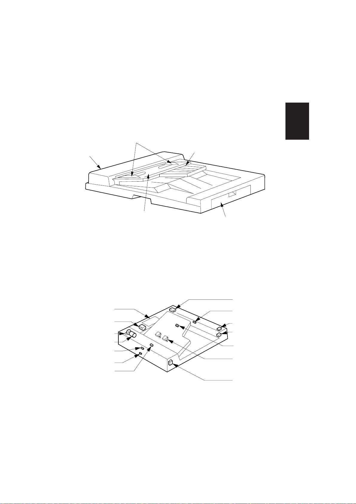
1.3 Exterior
Original feed
cover
1.4 Interior
Original guide
Original feed tray
Introduction
Original size
indicator
Original exit cover
SV027
Reverse motor
CPU
Transfer belt
motor
Clock sensor
Original feed
motor
Registration
sensor
Timing sensor
Original
detecting sensor
Exit/Reverse
sensor
Original exit cover
open/close sensor
Reverse solenoid
Original size
sensor
Original size
switch
Original feed cover
open/close switch
SV012
1-3
Page 6
Section II Sequence
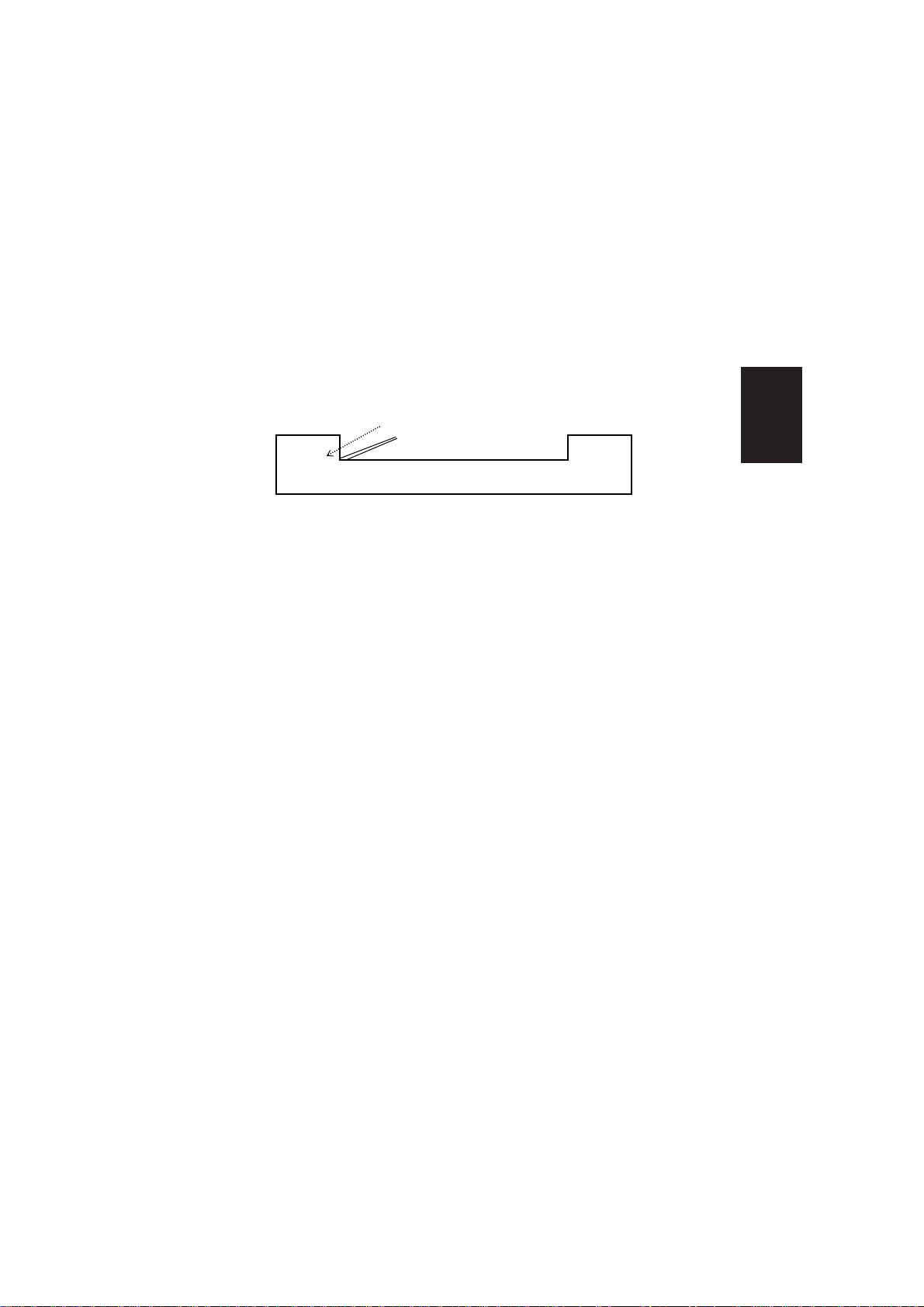
2.1 Original paper feed system
(1) The original is transported from the original feed tray to the original
registration roller.
Originals
SV028
1) When the wait/stopper solenoid is ON and the stopper and weight have
lowered, movement of the originals from the original feed tray becomes
possible.
2) After the original feed motor stops for 50msec (300msec to 1st paper) it starts
to rotate normally and transfers the original in the direction of the registration
roller.
3) The original arrives at the registration sensor within 2200msec for the JAM
timer (1) , when the pulse count reaches 100, the original feed motor stops.
(If the original is not detected by the registration sensor within 2200msec, a
paper jam will be indicated.)
4) After the original feed motor stops for 50msec, it starts to rotate in reverse
moving the original in the direction of the platen glass.
5) When the original feed motor reaches a predetermined count, it stops and
lead edge of the original is stopped approximately 42mm into the registration
roller.
Structure
2-1
Page 7
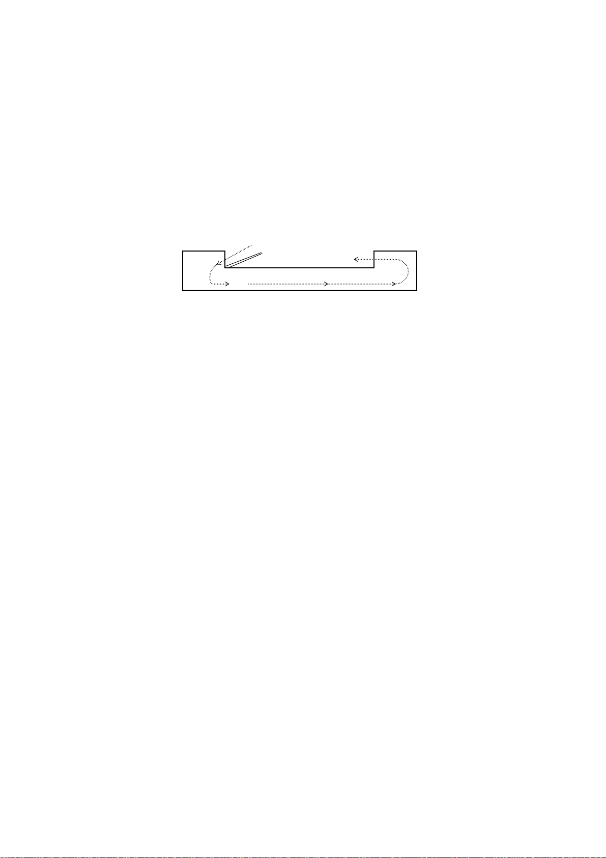
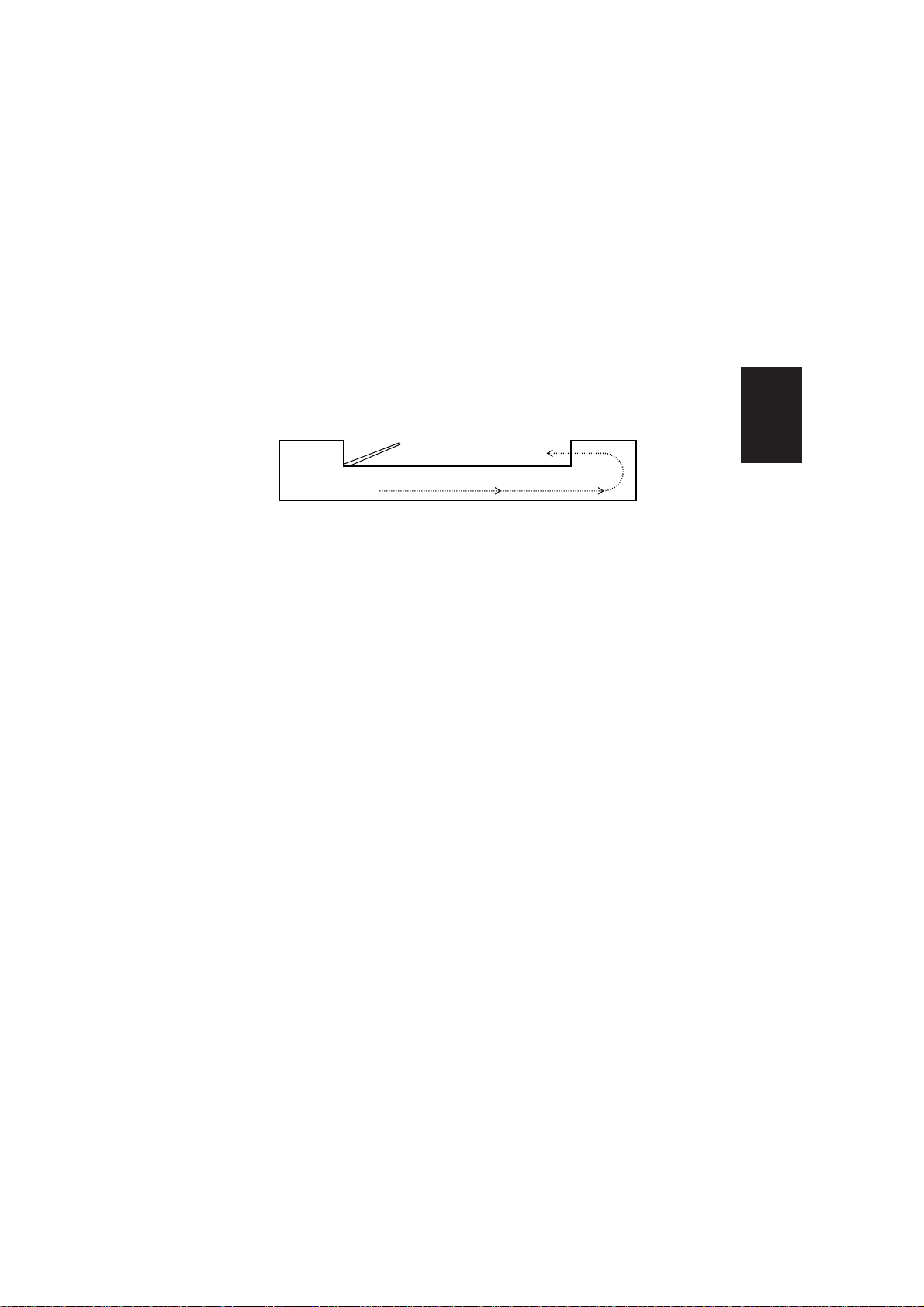
(2) One-sided original feed
• This operation feeds the original from the original feed tray onto the platen glass.
(During this operation, if an original is already on the platen glass, that original
will exit.)
SV029
1) When an original is not on the original timing feed position, original timing
feed operation begins.
2) After 50msec, the transport belt motor begins to rotate normally. (At this time,
JAM timer (3) starts its count to 1225msec.)
3) After 105msec, the original feed motor reverse rotation commences. (At this
time, JAM timer (2) starts its count to 840msec.)
4) When the original arrives at the original exit/reverse sensor within 1225msec
for JAM timer(3), the count is started for JAM timer (5) to 1080msec and the
original reverse motor deceleration pulse.
5) When the count of the original reverse motor deceleration pulse is increased,
the original reverse motor switches from high gear to low gear.
6) When the original passes the original exit/reverse sensor within 1080msec for
JAM timer(5), the original exit motor stop pulse starts its count to 30.
7) When the original reverse motor stop pulse count increases, the original reverse
motor stops.
8) When the original passes the registration sensor within 840msec for JAM
timer(2), the original feed stop pulse of the transport belt motor starts the
count to 187.
9) At the same time, the original feed motor stops.
10) When the rotational pulse of the transport belt motor increases to a
predetermined pulse count, the transport belt motor stops.
11) After 50msec, the transport belt motor reverse rotation begins at a low speed.
12) When the rotational pulse of the transport belt motor increases to 63 pulse
count, the transport belt motor stops. (Only in switch back)
2-2
Page 8

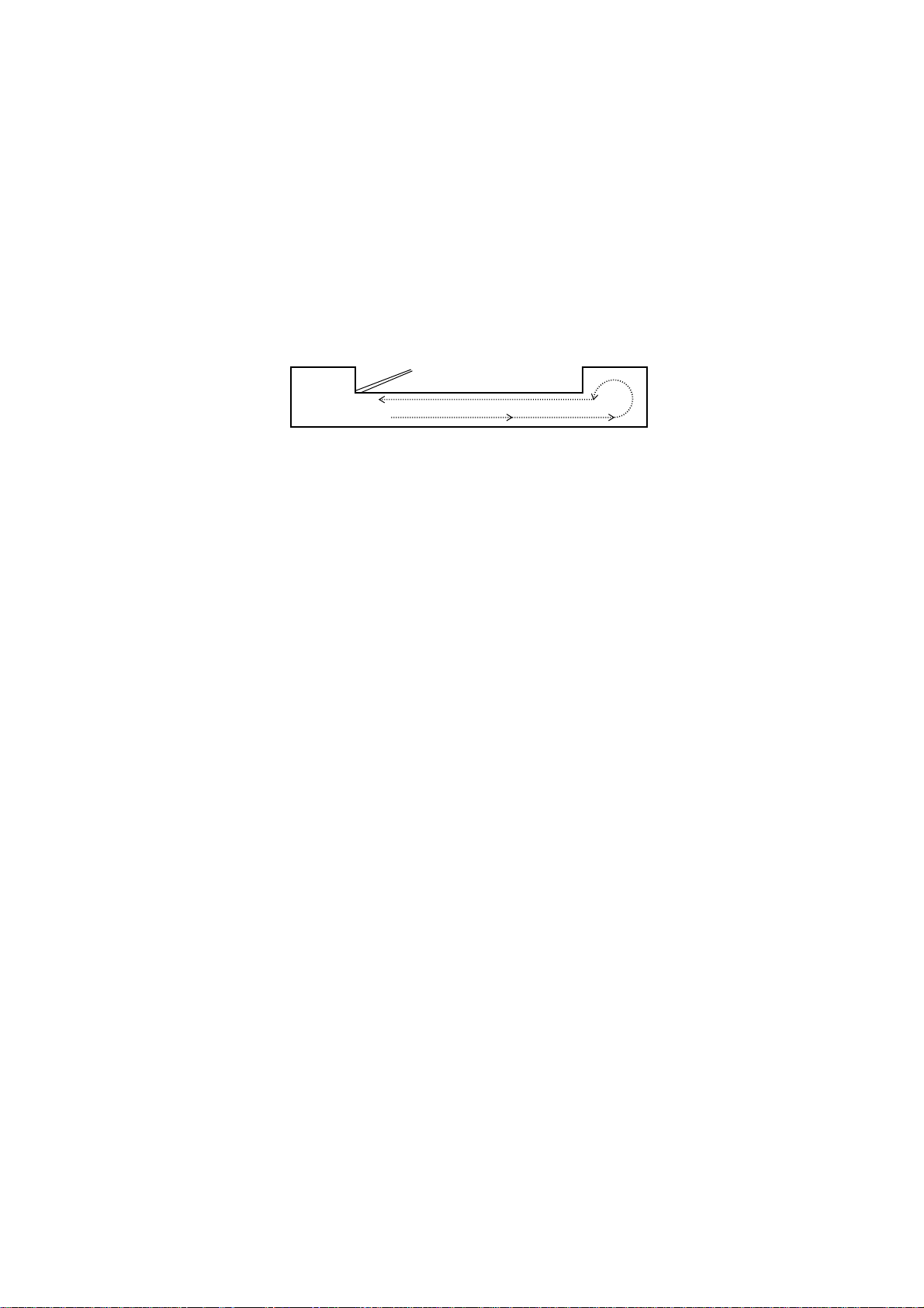
(3) Two-sided original feed
• This operation turns over the original at the reverse section then feeds it to the
platen glass. (During this operation, if an original is already on the platen glass,
that original will exit.)
SV030
1) When the original is not in the original timing feed position, the original timing
feed operation begins.
2) After 50msec, the original reverse and exit motor begins to rotate
simultaneously. (At this time, JAM timer (3) starts it count to 1225msec.)
3) After 100msec of the original feed motor reverse start timer, the original feed
motor reverse rotation begins. (At this time, JAM timer starts its count to
840msec, and JAM timer starts it count to 1585msec.)
4) When an original is on the platen glass, JAM timer(6) within 1585msec, and
the original timing feed position original JAM timer(3) within 1225msec have
arrived at the original exit/reverse sensor, and have passed the registration
sensor within 840msec of JAM timer(2), the original on the platen glass is
exited, and the original timing feed position original is reversed.
Structure
2-3
Page 9
(4) 2 in 1 feed
• This operation feeds two originals in one pair from the original feed tray onto the
platen glass.
(During this operation, if an original is already on the platen glass, that original
will exit.)
7) ~ 12)
1) ~ 6)
SV033
1) When the original is not on the original timing feed position, the original timing
feed operation begins.
2) After the original timing feed operation, the transport motor begins to rotate
normally.
3) After 105msec, the original feed motor reverse rotation commences.
(At this time, JAM timer stopped by the timing sensor starts its count to
955msec.)
4) When the original passes the timing sensor within 955msec, the original feed
stop pulse of the transport belt motor starts its count to 103. And at the same
time the original feed motor stops.
5) When the rotational pulse of the transport motor increases to a predetermined
pulse count, the transport motor stops. (If an odd number, the original is not
flipped over.)
6) The original timing feed operation begins. (In an even number, the original is
fed.)
7) When the original of an even number arrives at the registration sensor, and
the count increases to 100, the original feed motor stops.
8) The original feed motor reverse rotation begins. <Start of 2 in 1 original feed >
9) After timing sensor is turned ON, the transport motor begins to rotate normally
by 7 pulses.
10) When the transport motor begins to rotate normally by, two originals in one
pair are transported to the platen glass.
When the original passes the timing sensor, pulse count to stop original feed by the
11)
transport belt motor starts to 135. At the same time the original feed motor stops.
12)
The rotational pulse of the transport motor reaches pre-fixed number, the
transport motor stops. (Completion of original set on the glass surface)
2-4
Page 10
2.2 Original paper exit system
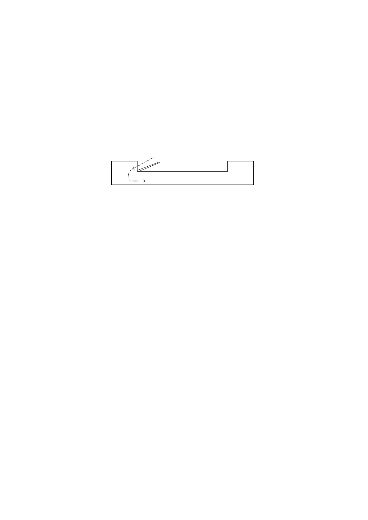
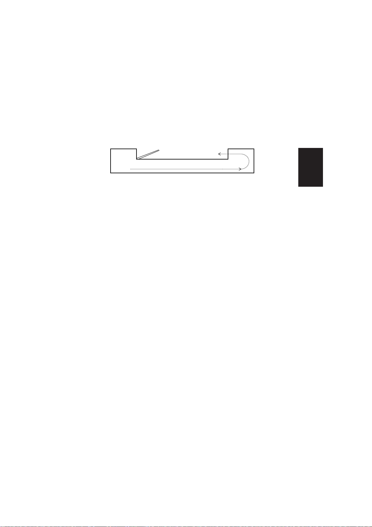
(1) Original Exiting
• This operation exits the originals. When a page with the lower page number of
original is not facing downward, the original will be turned over before being
exited. (The originals are always exited so that the page with lower page number
is on top.)
SV031
1) Only when the original is in the original timing feed position, one-sided original
feeding is done. The original on the platen glass is exited, and the original on
the timing feed position is moved to the platen glass. (When exiting both, the
original on the platen glass and the original on the timing feed position is
done, only when it is necessary is a reversal done.)
2) After completion of the transfer in 1) above, the reverse transport belt motor
begins to rotate normally. (At this time, JAM timer (3) starts its count to
1225msec.)
3) When the original arrives at the original exit/reverse sensor within 1225msec
of JAM timer (3), the original reverse motor begins the deceleration pulse
count. (At this time, JAM timer (5) starts its count to 1080msec.)
4) When the count of the original reverse motor deceleration pulse increases,
the original reverse motor switches from high gear to low gear.
5) When the original passes the original exit/reverse sensor within 1080msec of
JAM timer (5), the transport motor stops. Simultaneously, the original reverse
motor stop pulse begins its count to 307.
6) When the original reverse motor stop pulse increases to 307, the original
reverse motor stops.
Structure
2-5
Page 11
(2) Original reverse feeding
• This operation takes the original on the platen glass turns it over then places it
on the platen glass.
SV032
1) After 50msec, the transport belt motor begins to rotate normally. At this time,
the original reverse solenoid is turned ON, and the original is now in a position
where it can be reversed.
2) Simultaneously, JAM timer (3) starts its count to 1225msec.
3) The original reverse motor starts.
4) When the original arrives at the original exit/reverse sensor within 1225msec
of JAM timer (3), both the transport belt motor and the reverse motor stop and
the rotational pulse of the original reverse motor is started to count.
5) After 50msec, the transport belt motor begins to rotate in reverse. And after
40msec, the original reverse motor starts. At this time JAM timer (4) begins
its count to 1000 msec.
6) When the original has passed the original exit/reverse sensor within 1000msec
of JAM timer (4), the rotational pulse that is counted is switched from the
original reverse motor to the transport belt motor.
7) When the rotational pulse of the transport belt motor is increased to 2476,
both the transport belt motor and the original reverse motor stop.
2-6
Page 12
(3) 2 in 1 Original exit operation
1) ~ 6)
7) ~ 8)
SV034
1) The original reverse motor and the transport motor begin to rotate normally.
At this time, when the original does not arrive at the original reverse/exit sensor
within 1395msec of JAM timer, the original stop pulse of the transport motor
begins its count to 732.
2) When the original arrives at the reverse/exit sensor within 1395msec, the the
deceleration pulse of the original reverse motor begins to count.
At this time JAM timer stopped at the reverse/exit sensor begins its count to
2600msec.
3) When the original stop pulse of the transport motor increases its count, the
transport motor stops.
4) When the deceleration pulse of the original reverse motor increases, the
reverse motor is switched from high gear to low gear.
5) When the reverse/exit sensor is turned OFF, the timer delayed the second
original exit starts its count to 60msec.
6) When the delayed timer increases, the transport motor begins to rotate
normally.
7) When the original has passed the original reverse/exit sensor, the transport
motor stops. Simultaneously the original reverse motor stop pulse starts its
count to 424.
8) When the original reverse motor stop pulse is increased to 424, the reverse
motor stops.
Structure
2-7
Page 13
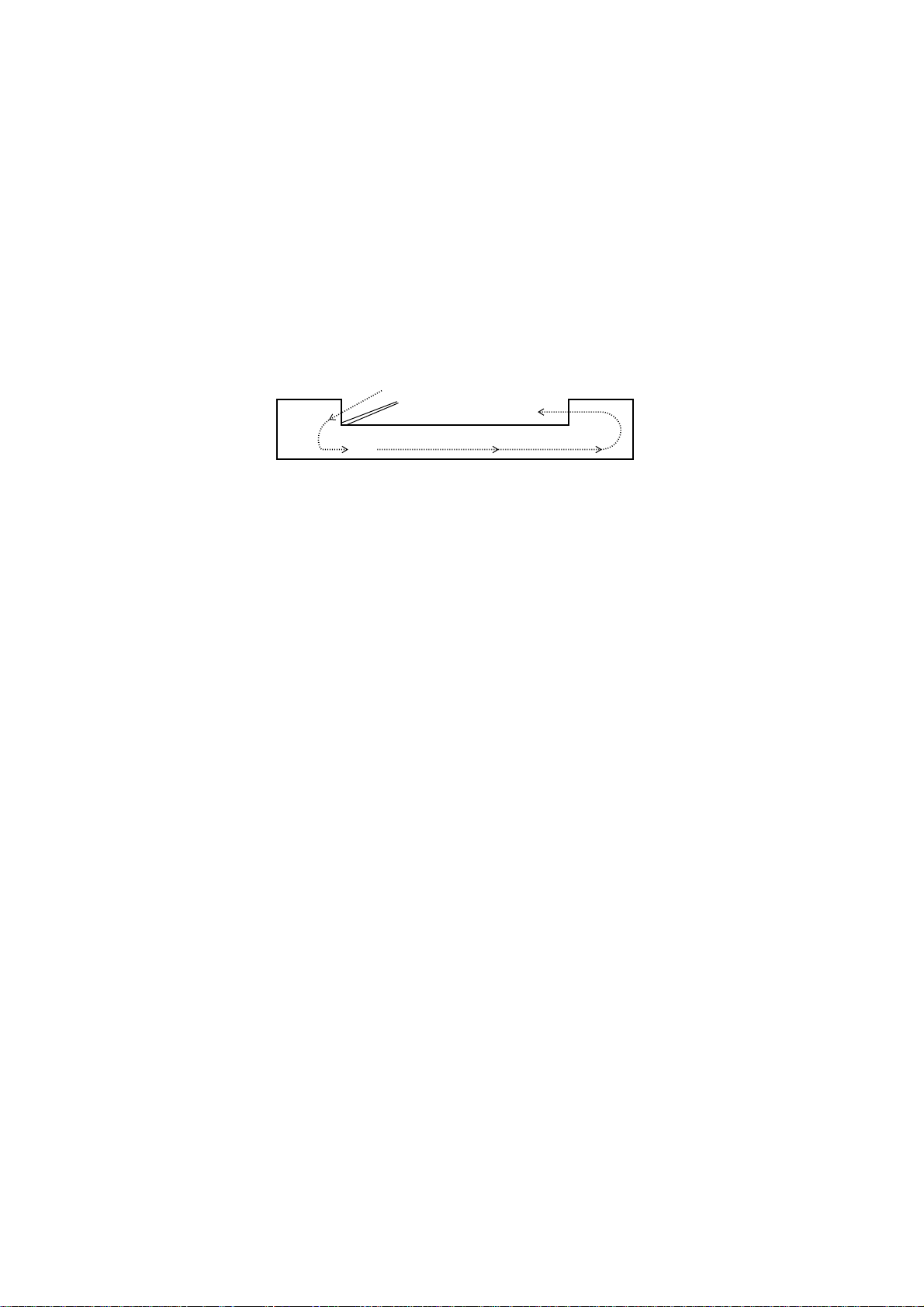
2.3 Original count system
(1) Original count
• This operation counts the originals. It consists of 2 operations, one is the original
feed count, and the other is the original exit count, and each operates
simultaneously.
SV029
1) When the wait solenoid is turned ON, the stopper and the weight are moved
downward and the originals on the original feed tray can move.
2) After 100msec, the reverse motor stops.
3) After 30msec, the transport belt motor begins to rotate normally.
4) After 170msec, the original feed motor begins to rotate normally and the original
is moved in the direction of the registration roller. (At this time JAM timer (1)
starts to count to 220msec.)
5) When the original arrives at the registration sensor within 2200msec of JAM
timer (1) and 100 pulse count is started, the original feed motor stops. The
original waits until it is pressed against the registration roller.
6) After the original feed motor stops and 50msec has elapsed, the original feed
motor begins to rotate in reverse, and the original is moved in the direction of
the platen glass. (At this time, the counts of JAM timer (2) to 840msec and
JAM timer (7) to 1595msec are started.)
7)
When the original has passed the timing sensor within 840msec of JAM timer
(2), the original feed motor stops. (At this time, when an original is in the original
feed tray, and 50msec has elapsed, the original feed operation is repeated.)
8) When the original has passed the original exit/reverse sensor within 1080msec
of JAM timer (7), the count of the original reverse motor deceleration pulse is
started. (At this time, the count of JAM timer (5) starts to 1080msec.)
9) When the count of the original reverse motor deceleration pulse is increased,
the original reverse motor is switched from high to low speed.
10) When the original passes the original exit/reverse sensor within a
predetermined time of JAM timer (5), the transport belt motor stops and the
original reverse motor stop pulse starts to count to 307.
11) When the count of the original reverse motor stop pulse is increased to307,
the original reverse motor stops. (At this time, when all of the originals have
2-8
not yet exited, it will switch from low gear to high speed without stopping.)
Page 14

Section III Maintenance
3.1 Maintenance chart
• In addition to the following maintenance table, the transport belt must be cleaned
as part of regular service calls.
• The timing of regular maintenance is determined on the basis of the number of
ADF original feed count.
Part name
Original feed roller
PF2217P316A
Original pick-up roller
PF2214P471A
DFP roller
PF2217K050A
Registration roller
PF2214P301A
Registration sensor
PF2214K224A
Timing sensor
PF2214K224A
Original reverse roller
PF2217P317A
Original exit roller
PF2214P323B
Original exit/
reverse sensor
PF2214K222A
Maintenance interval
Cleaning Replacement
Every
120,000
copies
Every
40,000
copies
—
Remarks
Brush, waste, air
blower, isopropyl
alcohol
NOTE: Minimum
quantity of
isopropyl
alcohol should
be used and be
wiped
immediately
after its use.
Maintenance
Transport belt
PF2214P353A
Every
120,000
copies
3-1
Page 15
3.2 Disassembly and Assembly
(1) Cleaning
1
Pick-up roller
SV001
2
5
2
Clean the pick-up roller by rotating it.
SV001
1 Open the original feed cover and clean
the parts below.
2 Original feed roller.
3 Original double feed prevention roller
(mounted on the feed cover).
1
3
4
4 Registration rollers.
5 Registration sensor.
6 Reflection seal for the sensor (mounted
on the feed cover).
6
SV002
3-2
SV002
3
2
3
4
2
1
SV003
SV003
1 Open the ADF.
2 Remove the screws (x 2).
3 Open the registration roller guide.
4 Clean the timing sensor and the reflection
seal.
Page 16
(1) Cleaning (continued)
4
Original exit roller
SV004
5
1
6
2
2
SV005
Clean the original exit rollers.
SV004
1 Open the original exit cover.
2 Clean the reverse rollers.
SV005
1 Open the ADF.
2 Remove the screws and star-washers
Maintenance
(x 2).
3 Remove the exit guide.
3
5
4
4 Clean the reflection seal for the sensor.
5 Clean the original exit sensor.
Note: Check the condition of the guide mylar
and replace as required.
1
2
SV006
SV006
3-3
Page 17
(2) To replace the DFP roller
1
2
3
2
2
DFP roller ass'y
1
3
1
SV007
1
SV008
1
2
4
3
2
3
SV009
1 Open the original feed cover.
2 Remove the screws (x 2).
3 Remove the DFP roller unit.
Note: This procedure is performed easier
with the ADF down, or closed.
Be careful to avoid damaging the guide
mylar.
SV007
1 Remove the screws (x 2).
2 Remove the DFP roller ass'y.
Note: Be careful to avoid damaging the
mylars.
SV008
1 Remove the springs (x 2).
2 Remove the DFP roller (ass'y).
3 Remove the bearings (x 2).
4 Remove the DFP roller.
Note: (1) Note the position of the spring for
use in re-assembly.
(2) Do not lose the bearings.
(3) Clean the roller after re-assembly.
(4) Re-assemble in reverse order.
SV009
3-4
Page 18
(3) Replacement of the transport belt
SV014
1
1 Open the ADF to the service position.
2 Remove the screws (with star-washers)
on the upper frame (x 2).
2
Transfer belt
2
3
Transfer belt
assembly
2
SV010
Remove the transport belt assembly.
Maintenance
SV011
Remove the screws (with star-washers)
(x 2).
SV014
4
1 Pull up the frame of the transport.
2 Remove the belt.
Note: During re-assembly, be careful to avoid
1
pinching the belt in the frame. (Belt
must be inside the frame flange.)
2
3 Re-assemble in reverse order.
Note: Confirm that the drive belt is correctly
SV015
SV015
aligned on the belt drive pulley.
3-5
Page 19
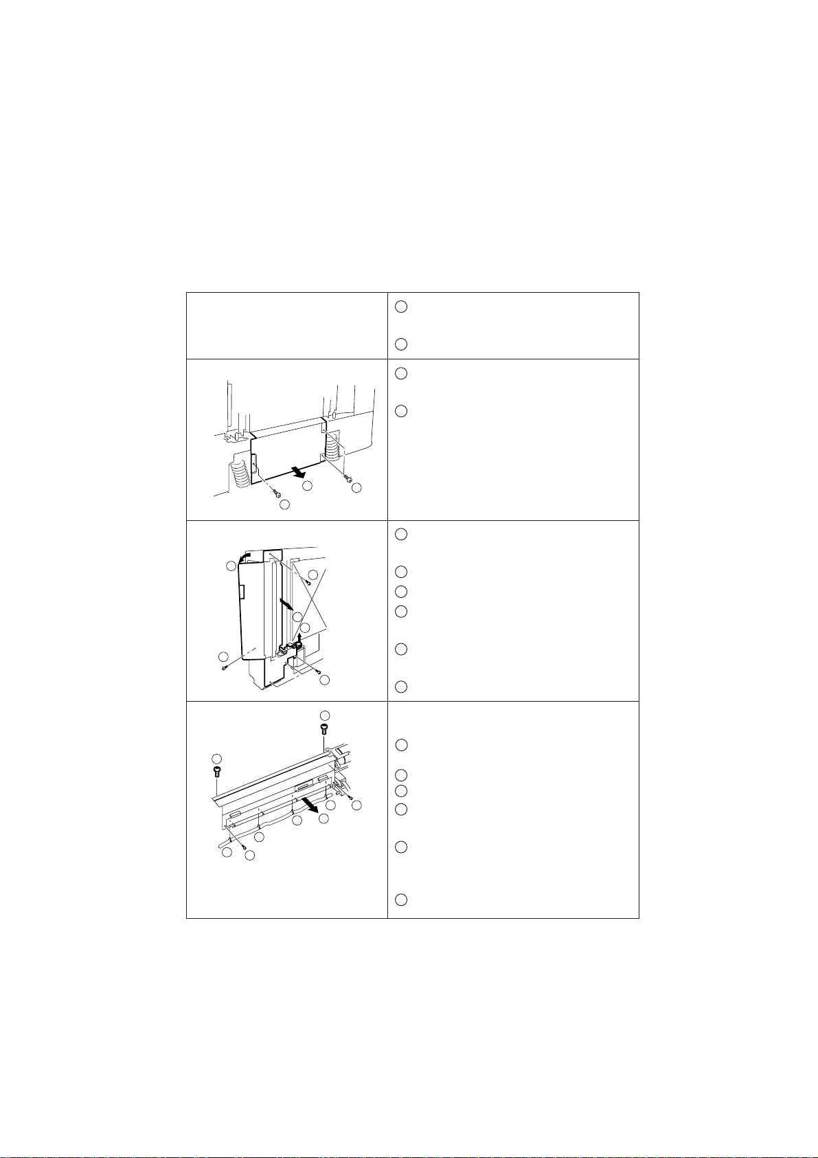
(4) Replacement of the pick-up and the original feed rollers
1
1 Remove the original feed tray (2 screws,
1 connector).
2 Open the ADF to the service position.
1 Remove the screws (with star-washers)
2
(x 3).
2 Remove the bottom cover.
2
1
3
2
3
1
SV017
SV017
1 Remove the original feed drive belt ass'y
(2 screws).
2 Open the original feed cover.
3 Remove the screws (x 5).
5
4
3
4 Slide the drive belt OFF of the drive motor
pulley.
5 Lower the original feed unit onto the copier
top left cover.
3
SV018
SV018
6 Disconnect the four(4) connectors.
3-6
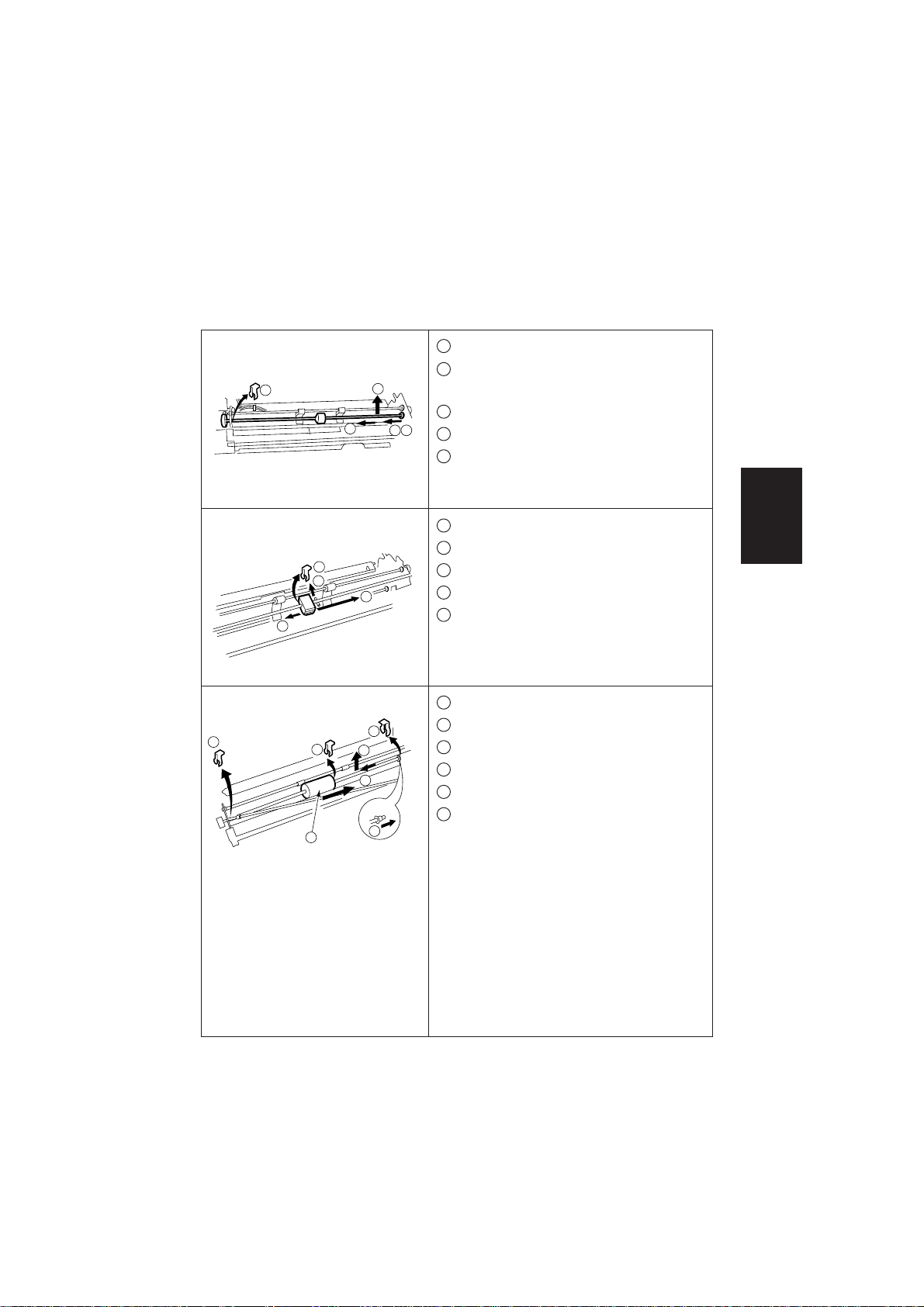
4
3
Turn the feed unit over and rest it on the
original feed cover.
1 Remove (or detach the harness from) four
3
1
2
6
1
1
1
2
SV019
SV019
mini-clamps.
2 Remove the screws (x 2).
3 Loosen two screws.
4 Rotate the pick-up roller so it is below the
tray guide.
5 Remove the original feed tray connector
(2 screws) push the connector back
through the hole.
6 Remove the original feed tray guide.
Page 20
(4) Replacement of the pick-up and the original feed rollers (continued)
5
1 Remove the rear touch ring.
2 Slide the shaft of the pick-up roller toward
1
4
the motor.
3 Slide the bearing toward the left.
2
3 5
4 Pull the shaft upward.
5 Remove the bearing.
SV020
SV020
6
2
4
5
3
1 Remove the front touch ring.
2 Remove the center touch ring.
3 Slide the pick-up roller toward the left.
4 Pull the pin out.
5 Slide the pick-up roller toward the front
and remove it.
Maintenance
SV021
SV021
7
1
5
3
4
2
1 Remove the touch rings on both sides.
2 Slide the roller shaft toward the motor.
3 Pull the shaft up.
4 Remove the bearing on the front side.
5 Remove the touch ring.
6 Slide the original feed roller to the front
6
4
side and remove it.
SV022
SV022
Note: During re-installation, the roller should
rotate freely counter-clockwise and
lock if turned clockwise.
3-7
Page 21
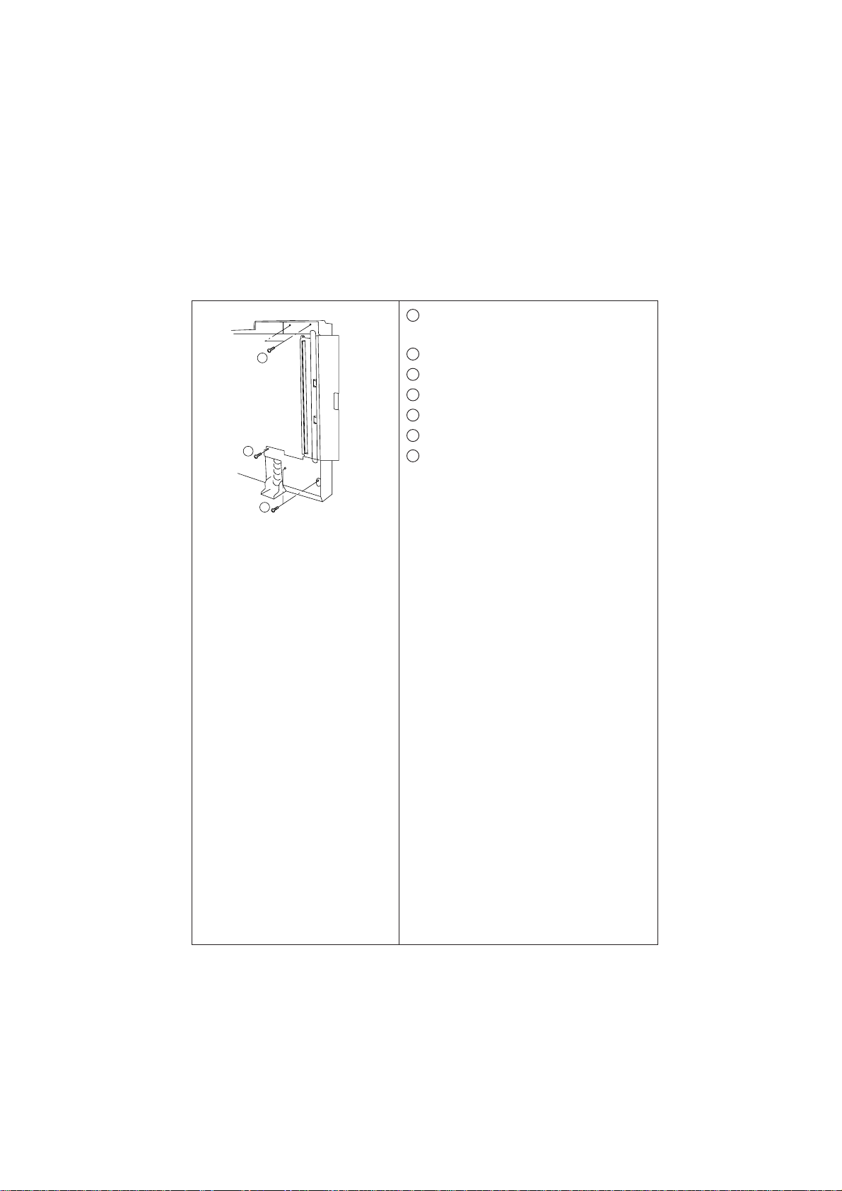
(5) Exit assembly removal procedure
5
5
5
SV047
1 Conduct the procedure 1 and 2 of page
3-5.
2 Conduct the procedure 2 of page 3-6.
3 Disconnect ADF CPU CN6 and CN7.
4 Cover the platen glass with clean copier paper.
5
Remove the exit ass'y mounting screws (x 5).
6 Lower the exit ass'y onto the platen glass.
7 Remove CN6 and CN7 harness from the LWS.
3-8
Page 22
3.3 Adjustment
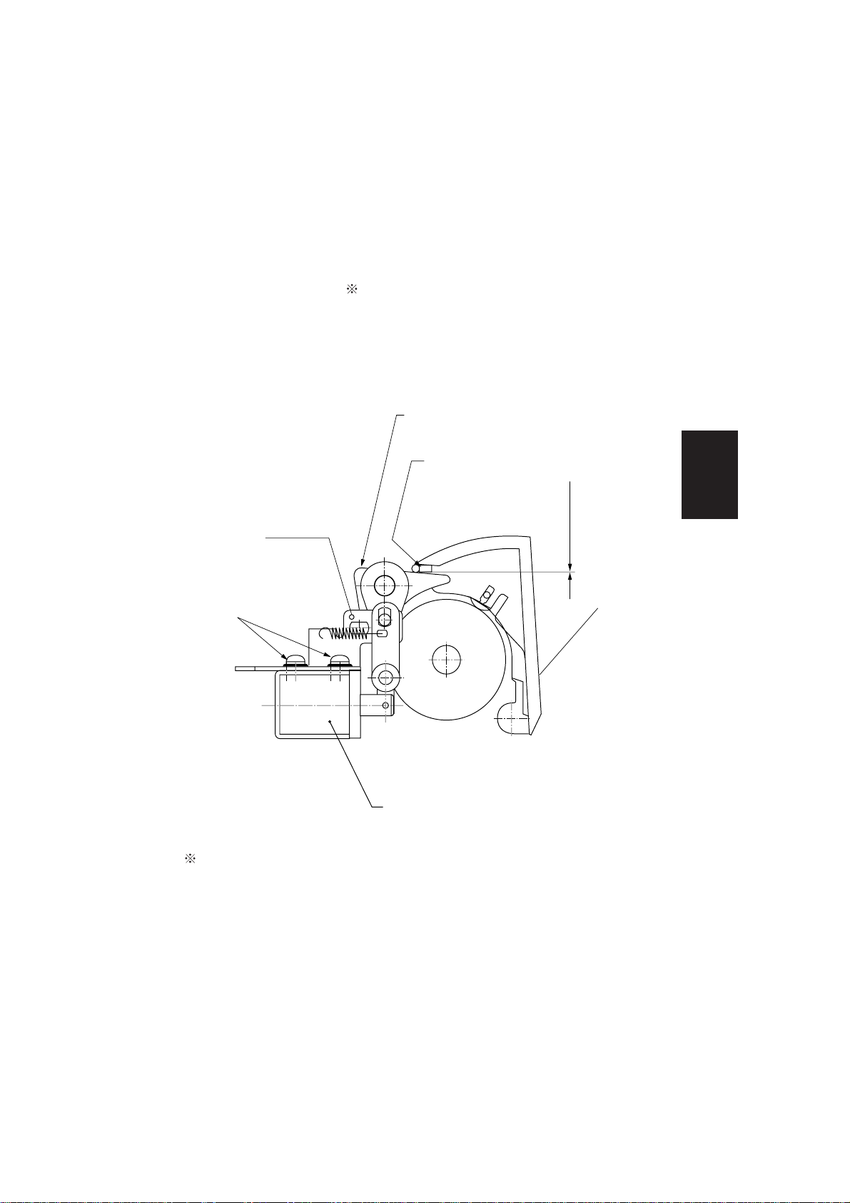
(1) Switching original exit
• With the solenoid screws loose, manually engage the plunger into the solenoid.
While holding the plunger engaged, slide the solenoid side to side to obtain a
0 - 5mm gap between the flapper and flapper rubber.
Flapper
Flapper rubber
Flapper
solenoid
bracket
Screws
SV035
Reverse
solenoid
To perform this adjustment, the exit assembly must be removed.
Maintenance
0 ~0.5mm
Exit cover
3-9
Page 23
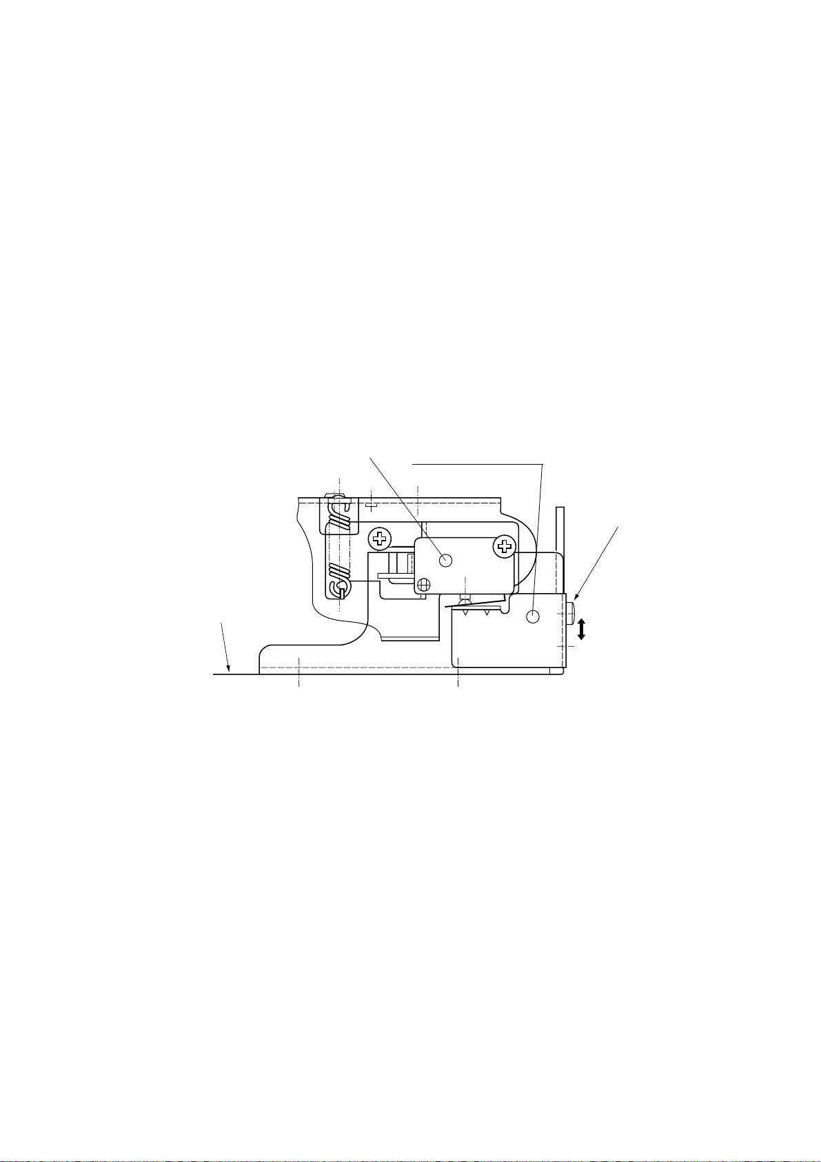
(2) ADF open/close detecting switch adjustment
• Perform this adjustment when the ADF open/close action is not detected.
1) Open the ADF.
2) Remove the ADF CPU cover (3 screws with star washers).
3) Loosen the screw retaining the switch lever.
4) Turn the switch lever in the direction of the arrow. Open the ADF 10 to 70mm
from the copier, and close the ADF 10 to 30mm from the copier, while checking
the display of copier.
ADF open/close
switch
Switch lever
Copier upper
cover (Rear)
Screw
5) Slide the switch lever so the ADF open/close switch is actuated when the
ADF is opened 10 to 30mm from the platen glass. Confirm by placing an
original in the infeed guide and opening/closing the ADF while watching the
copier display.
3-10
SV036
Page 24
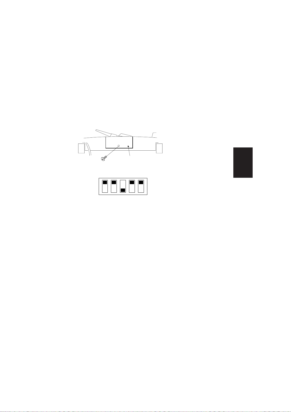
(3) Registration sensor and original exit/reverse sensor adjustment
• Perform this adjustment after replacing ADF CPU P.C.B. , registration sensor or
original exit/reverse sensor.
NOTE: Make sure no originals are in the ADF.
1) Turn the copier power switch OFF.
2) Remove the ADF service cover (1 screw).
Service cover
SV043
SV043
3) Set the ADF CPU PCB dip switches as follows:
ON
OFF
12345
4) Turn the copier power switch ON. The LED of ADF CPU PCB will flash.
(This is normal before pressing PSW1.)
5) The sensor adjustment and E2PROM initialization will be automatically
performed when the push switch (PSW1) is pressed on the ADF CPU PCB.
6) When the sensor adjustments are completed, the LED will turn OFF.
If an adjustment error is detected, the LED will be illuminated as follows:
a) Registration roller sensor: Lights up
b) Timing sensor: Flashes slowly (100msec interval)
c) Exit/Reverse sensor: Flashes quickly (500msec interval)
Repeat steps 1 to 5. If an error still remains, replace the indicated defective
sensor and repeat the procedure.
7) Turn OFF the all DIP switches (SW1) on the ADF CPU PCB after the adjustment
and turn the copier power switch OFF and ON.
8) Re-install the ADF service cover.
Maintenance
3-11
Page 25
Section IV Electrical
4. 1 Function of electrical parts
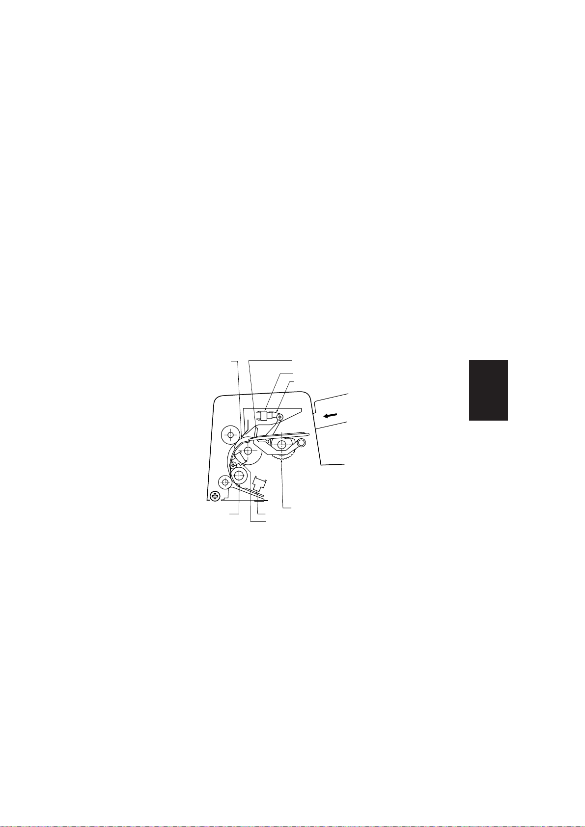
(1) Original detecting sensor / Registration roller sensor
( Original detecting sensor )
•Detects originals in the original feed tray.
1) When an original is loaded in the original feed tray, it will contact the original
stopper. The original detecting sensor lever, which is positioned in front of the
original stopper, is raised and detects the presence of an original.
2) As soon as the original is detected, the ADF indicator in the copier's display
lights up and ADF operation is enabled.
Original
feed roller
Regist roller
( Registration roller sensor )
•Detects the original feed status and counts the number of originals.
1) When the paper feed roller is rotated, an original is fed to the registration roller,
then registration roller rotates to feed the original. The registration roller sensor
counts the number of originals which pass and informs the copier.
Original stopper
Original detecting sensor
Original detecting sensor lever
Pick up roller
Timing sensor
Regist roller sensor
SV037
Electrical
4-1
Page 26

( Timing sensor )
•Detects the tail edge of original
1) During registration roller operation, an original is fed to the transport belt. At the
same time, the timing sensor detects the tail edge of the original to control
original feed operation.
(2)Weight / Stopper solenoid
1) When the weight/stopper solenoid turns ON( 1 ), weight shaft rotates in the
direction indicated by arrow( 2 ) and the weight plate contacts ( 3 ) the original.
The pressure is determined by the weight of the weight plate and tension of the
spring.
2) At the same time, the original stopper is moved below the paper guide(
4 ).
Weight shaft
Original stopper
2
1
Stopper shaft
Paper guideWeight plate
Stopper shaft
4
3
SV038
4-2
Page 27

(3) Original feed drive
•In order to feed an original, the motor rotates the paper feed and pick-up rollers.
1) When the original feed motor rotates ( forward rotation / A direction ), pully 56
is driven by timing belt 82, and one way pully 18 (which is mounted on the
same shaft) also rotates.
2) At the same time, pully 50 is driven by timing belt 72, and gear 21 (which is
mounted on the same shaft) also rotates.
3) Then gear 30, 32, 32OW also rotate as well as the pick-up roller and paper feed
roller .
•In order to feed the original from the original feed area to the transport belt, the
registration roller also rotates.
1) When the original feed roller is driven ( reverse rotation / B direction ), pully 56
is driven by pully 20 and timing belt 82, and one way gear 30OW (which is
mounted on the same shaft) also rotates.
2) At the same time, gear 21 is also driven so the registration roller turns.
Pully 56
Gear 30 ow
Timing belt
72
Registration
roller
Pully
18 ow
Original
feed
Gear
roller
32
Gear 21
Timing belt 82
A
Gear 21
B
Pully 50
Pully 20
Original feed roller
Pick up
roller
Gear
Gear
30 ow
32 ow
Electrical
SV024
4-3
Page 28

(4) Transport belt motor
•Rotates the transport belt to feed the original
1) When belt motor pully 37 is driven ( forward rotation), pully 24 is driven by
timing belt 136, and pully 24 (which is mounted on the same shaft) also rotates.
2) At the same time, pully 30 is driven by timing belt 60 and the belt roller (L) is
driven ( forward rotation ) rotating the transfer belt.
Pully 24
Belt roller (L)
Pully 37
Transport belt
Transport belt motor
Pully 30
Timing belt 136
Timing belt 60
SV023
(5) Reverse motor
• In order to reverse and exit the original, the original exit roller and original reverse
roller are driven.
1) When the reverse motor drives ( Forward rotation), the original reverse roller is
driven by Pully 28/31 and timing belt 56.
2) At same time, timing belt 44 and pully 17 are driven then original exit roller
rotates.
Original reverse motor
Timing belt 44
Pully 17
Link 1 Link 2
Original exit roller
Pully 28/31
Timing belt 56
Original reverse roller
Reverse claw
SV025
Reverse
solenoid
4-4
Page 29

(6) Original reverse solenoid
• This solenoid engages the reverse claw which switches driven direction of the
original.
( refer to figure page 4-4 )
1) When the reverse solenoid turns ON, link 2 moves in the direction indicated by
arrow.
2) The reverse claw is raised to turn the original over and feed it to the platen
glass.
3) When the original reverse solenoid turns OFF, the reverse claw lowers to exit
the original.
4) Consequently, switching between reversing and exiting the original is determined
by ON/OFF status of the original reverse solenoid.
(7) Original exit/reverse sensor
• Detects the feeding status of an original which was turned over at the reverse
section. Also, detects an original that has exited the ADF.
1) The original exit/reverse sensor is mounted near the reverse roller to detect the
feeding and exit status of original.
Original exit/reverse
sensor
Original reverse
roller
Reverse
claw
Electrical
Link 1
Link 2
Reverse solenoid
SV039
4-5
Page 30

(8)ADF open/close detecting switch
•Detects the open/close status of the ADF and activates the reset operation for
recovery from original Jams.
1)This switch constantly monitors the open/close status of the ADF by going OFF
when the ADF is opened or ON when it is closed. While the ADF is open, ADF
operation is disabled.
2) This sensor also activates reset after the ADF has been opened and closed as
a result of a original jam.
ADF open/close detecting switch
4-6
SV036
Page 31

(9) Original feed motor clock sensor
•Detects original feed motor speed and machine error by rotation pulses.
1) A timing disc has been installed on the original feed motor shaft. Depending on
the movement of the slits on the timing disc, the clock sensor switches ON/
OFF and outputs a timing pulse.
Original feed cover open/close
Original feed motor timing disk
detecting switch
SV040
(10) Original feed cover open / close detecting switch
•Detects the open/close status of the original feed cover and activates reset.
1) This sensor detects the open/close status of the original feed cover by going
OFF when the original feed cover is opened or going ON when the original
feed cover is closed. When the original feed cover is opened and closed, this
switch also activates reset for recovery from an original jam.
(11) Original exit cover open / close detecting switch
•Detects the open/close status of the original exit cover and activates the reset
operation.
1) This sensor detects the open/close status of the original exit cover by going
OFF when the original exit cover is opened or going ON when it is closed.
While the original exit cover is open, ADF operation is disabled.
2) When the original exit cover is opened and closed, this switch also activates
the reset operation for recovery from an original jam.
Original exit cover open/close
detecting switch
Electrical
SV041
4-7
Page 32

(12) Original size detecting sensor
•Detects the size of original loaded in the original feed tray
1) When an original is loaded and the original guides are adjusted to fit the size of
original, the size of original is detected by the ON/OFF status of three original
size detecting sensors which are mounted on the original feed tray.
2)Original size detecting sensor (2) and (3) consist of a micro switch, where as
original size detecting sensor (1) consists of photointerruptor.
Original size
detecting sensor
(1)
Original size
detecting sensor
(2), (3)
SV042
4-8
Page 33

4.2 Signal information by connector
(1) CPU P.C.B.
(CN1)
1
2
3
4
5
6
7
1
2
3
4
5
6
7
8
9
10
11
12
Signal
name
GND
STL
VL
SWH1
GND
SWH2
GND
Signal
name
VL
GND
EMP
GND
KMCLK
VL
VL
TIMS
TIMS DA
VL
REGS
REGS DA
Destination
Original size detecting
sensor (1) CN13-3
Original size detecting
sensor (1) CN13-2
Original size detecting
sensor (1) CN13-1
Original size detecting
switch (2) CN31-1
Original size detecting
switch (2) CN31-2
Original size detecting
switch (3) CN31-3
Original size detecting
switch (3) CN31-4
Destination
Original detecting
sensor CN16-3
Original detecting
sensor CN16-2
Original detecting
sensor CN16-1
Paper feed motor clock
sensor CN17-3
Paper feed motor clock
sensor CN17-2
Paper feed motor clock
sensor CN17-1
Timing sensor
CN18-3
Timing sensor
CN18-2
Timing sensor
CN18-1
Registration roller
sensor CN19-3
Registration roller
sensor CN19-2
Registration roller
sensor CN19-1
ON/OFF
5V
5V
5V
OFF
0
ON
5V
OFF
0
ON
OFF
0
ON
ON/OFF
5V
0
No detecting detecting
Pulse signal
5V
0
No detecting detecting
5V
LED ON
OFF
No detecting detecting
OFF
LED ON
5V
3.8V
0
5V
3.8V
Pin
No.
(CN2)
Pin
No.
Function
Ground
Original size detecting
signal
DC +5V
0
Original size detecting
signal
Ground
Original size detecting
signal
Ground
Function
DC+5V
Ground
5V
Original detecting
0
signal
Ground
Paper feed motor clock
sensor signal
DC+5V
DC+5V
3V
Timing sensor output
1V
singal
Timing sensor control
signal
DC+5V
3V
Registration roller
1V
sensor output signal
Registration roller
sensor control signal
Electrical
4-9
Page 34

(CN3)
Pin
No.
1
2
3
4
5
6
(CN4)
Pin
No.
1
2
3
4
5
6
7
8
9
Signal
name
*B
B
*A
A
Vp
Vp
Signal
name
DFM1
DFM2
DFSO
Vp
FGOD
ADF Vp
AUOD
Vp
–
Destination
ON/OFF
Transfer belt motor
CN33-11
Transfer belt motor
CN33-7
Transfer belt motor
CN33-5
Transfer belt motor
CN33-1
Transfer belt motor
CN33-9
Transfer belt motor
CN33-3
Destination
ON/OFF
Original feed motor
CN21-1
Original feed motor
CN21-2
Original feed solenoid
CN35-1
Original feed solenoid
CN35-2
Original feed cover open/close
detecting switch CN23-1
Open Close
Original feed cover open/close
detecting switch CN23-2
ADFopen/close
detecting switch CN24-1
Open Close
ADF open/close
detecting switch CN24-2
–
Function
Transfer belt motor
OFF24V
signal
ON0
DC+24V
24V
0
DC+24V
Function
Original feed motor
drive signal
OFF24V
ON0
Solenoid control signal
24V
DC+24V
0
24V
Original feed cover open/
0
close detecting signal
24V
DC+24V
0
ADFOpen/close
24V
detecting signal
0
24V
DC+24V
–
4-10
(CN5)
Pin
No.
1
2
Signal
name
Vp
PGND
Destination
Connecting harness for
copier CN34-1
Connecting harness for
copier CN34-2
ON/OFF
24V
0
Function
DC+24V
Ground
Page 35

(CN6)
Pin
No.
1
2
3
4
5
6
7
8
(CN7)
Pin
No.
1
2
3
4
5
Signal
name
FD Vp
TGOD
Vp
Vp
*B
B
*A
A
Signal
name
AN Vp
HANS
RDDLED
Vp
DRSOL
Destination
Exit cover open/close
detecting switch CN25-1
Exit cover open/close
detecting switch CN25-2
Original reverse/exit
motor CN26-1
Original reverse/exit
motor CN26-2
Original reverse/exit
motor CN26-3
Original reverse/exit
motor CN26-4
Original reverse/exit
motor CN26-5
Original reverse/exit
motor CN26-6
Destination
Original reverse/exit
sensor CN28-3
Original reverse/exit
sensor CN28-2
Original reverse/exit
sensor CN28-1
Original reverse/exit
solenoid CN29-1
Original reverse/exit
solenoid CN29-2
ON/OFF
closeopen
ON/OFF
No detecting detecting
LED ON
OFF
24V
0
Function
24V
DC+24V
0
24V
Exit cover open/close
detecting signal
0
DC+24V
24V
0
DC+24V
Original reverse/exit
motor drive signal
OFF24V
ON0
Function
24V
DC+24V
0
13~3V
Original reverse/exit
1.6
sensor output signal
~0.4V
Sensor LED control
5V
3.8V
signal
24V
DC+24V
0
Original reverse/exit
OFF
sensor drive signal
ON
Electrical
4-11
Page 36

(CN8)
Pin
No.
1
2
3
4
5
6
7
Signal
name
IADFRX
ADFRX
GND
IADFTX
ADFTX
ADFCHGES
ADFFSFD
Destination
Connecting harness for
copier CN34-8
Connecting harness for
copier CN34-9
Connecting harness for
copier CN34-10
Connecting harness for
copier CN34-11
Connecting harness for
copier CN34-12
Connecting harness for
copier CN34-7
Connecting harness for
copier CN34-2
ON/OFF
Pulse signal
Pulse signal
No detecting detecting
5V
0
Function
ADF reverse receiving
signal
ADF receiving signal
Ground
ADF reverse
transmission signal
ADF transmission signal
Original change
subscription signal
One sided original feed
operation request signal
4-12
Page 37

4.3 Explanation of circuit
1.ADF CPU P.C.B.
(1) Comunication circuit
This circuit allows both serial and parallel communication between the copier
and the ADF. IC10 is used for serial communication. Data is transferred as
both a normal and inverse signal, so that any line noise will be cancelled out by
adding the two signals together inside IC10. The ADF also communicates with
the copier using 2 parallel data lines. One line for output using IC4 and Q3
(buffer) and the other for data input using pull up resistor.
CN8
1
IADFRX
2
ADFRX
3
GND
4
IADFTX
5
ADFTX
6
ADFCHGS
ADFFSFD
7
R92
100
+5V
2
R70
1.0k
+5V
R39
4.7k
R40
DA1
4.7k
DT
1
11
3
R43
4.7k
DA2
13
IC4
12
ADFFSFD
ADF
CHGES
+5V
IC10
RI1
RI1
DO1
*
DO1
*
RI2
R12
DO2
*
DO2
RO1
DI1
*RE
DE
RO2
DI2
3
15
4
12
5
9
SD003
1
*
2
14
13
6
7
10
11
(2)Sensor input circuit
1) Original size detecting switch ( SWH1/SWH2 )
Original size detecting switch (2) and (3) are micro switches for detecting original
width, and output of these switches are input to gatearray ( IC14 ) via a noise
filter which consists of resistors and capacitors, then input to the CPU through
data bus.
CN1
SWH1
4
5
GND
CN1
6
SWH2
7
GND
R42
4.7k
R41
4.7k
+5V
+5V
R23
10k
R22
10k
C24
0.1
C25
0.1
58
59
IC14
P5
P6
IC13
79
RxD
80
TxD
24
TXEN
Electrical
SD004
4-13
Page 38

2) Original size detecting sensor (1) (STL)
The original size detecting sensor (1) consists of a photointerruptor for detecting
original length, and output of this sensor is input to gatearray ( IC14 ) via noise
filter which consists of resistors and capacitors, then input to the CPU through
a data bus.
54
IC14
P1
SD005
CN1
3
2
1
VL
STL
GND
+5V
R37
+5V
4.7k
R10
10k
C26
0.1
3) Original detecting sensor (EMP)
The original detecting sensor consists of a photointerruptor, and output of this
sensor is input to gatearray ( IC14 ) via noise filter which consists of resistors,
capacitors, and Q14, then input to the CPU through a data bus.
IC14
1B
R36
10k
C2
GND
+5V
E3
DT
TP3
53
P0
SD006
CN2
1
3
2
VL
EMP
GND
GND
R1
180
15k
+5V
R75
R9
10k
GND
C26
0.1
4-14
Page 39

4) Original feed motor clock sensor ( KM CLK )
The original feed motor clock sensor consists of a photointerruptor and timing
plate (for monitoring motor rotation) and output of this sensor is input to the
CPU via a noise filter which consists of resistors and capacitors.
CN2
6
VL
5
KM CLK
4
GND
+5V
GND
R38
4.7k
R14
10k
GND
C33
1000p
TP12
74
IC13
INTP2
SD020
5) Registration sensor ( REGS ) / Timing sensor ( TIMS )
The registration sensor and timing sensor is a reflection type of photointerruptor
which consists of an LED and phototransistor. The phototransistor detects the
reflection of infrared light from the LED for detecting the original.
The cathode terminal of the LED is connected to a voltage-current converting
circuit and D-A output ( Analog voltage output ) from the CPU controls the input
current for the LED. In addition, the photocurrent of the phototransistor is
converted to a voltage value by resistors. They are connected to the input
terminal of the sensor, to the input comparator circuit via a noise filter for
comparing to the reference voltage ( Aprrox. +2V ). When the output voltage
from the sensor is higher than reference voltage, the output signal from the
comparator circuit becomes Low, and transfers to the CPU as no original
detection.
The CPU controls the input current for the LED ( brightness of LED ) to maintain
proper sensor output voltage.
VL
REGS DA
REGS
+5V
R34
9.1k
PGND
R15
10k
AN+24V
C8
0.1
R18
PGND
Q8
2SC2712
2
1
3
22k
R28
2k
R66
10k
R48
100k
9
8
IC1.2
27
14
IC3.3
5
6
TP8
R24
100
GND
TP13
C34
100pF
+5V
R17
10k
68
56
73
IC13
ANO1
INPT1
ANI0
SD007
CN2
7
9
CN2
8
Electrical
4-15
Page 40

6) Original exit / reverse sensor ( HANS )
The original exit/reverse sensor is a reflection type of photointerruptor which
consists of an LED and phototransistor. The phototransistor detects the reflection
of infrared light from the LED for detecting the original.
The sensor input voltage is divided 1/3 by R87 and R88 and inputs to the A-D
converter. Then PWM signal which is a corresponding output from the A-D
converter, is output from the gatearray ( IC14 ). This PWM signal is converted
to analog voltage by an integrating circuit ( R2, C12 ) and is amplified 2 times
by a non-inverting amplifier to be a reference voltage for the comparator.
The reference voltage for the comparater is 2/3 of the high level of each sensor
output.
Also,during a no original detecting condition, the input voltage to the CPU is
less than 1V, pin 49 of CPU becomes high to increase brightness of the LED.
RDDPWM
(IC14-18)
R2
10k
CN7
1
AN+24V
HANS
2
3
RDDLED
C12
0.1
R51
PGND
R89
3.3k
C11 0.1
22k
2
3
IC1.1
R52
22k
PGND
1
R90
2.2k
AN+24V
2
3
PGND
R35
10k
TP1
DT
PGND
1
C9
0.1
R4
10k
R87
3k
R88
1.5k
4
5
R47
IC3.1
100k
PGND
+5V
R24
10k
2
+5V
R3
10k
C29
0.1
D1
TPS
IC13
INTP3
75
58
ANI2
49
P12
4-16
SD008
Page 41

7) ADF open/close detecting switch,original feed cover open/close detecting switch,
original exit cover open/close switch( AUOD,FGOD,TGOD )input circuit.
This circuit is the input circuit for the ADF open/close detecting switch, original
feed cover open/close detecting switch, and exit cover open/close detecting
switch. When one of these switches are in the OFF condition, the power ( DC
24V ) to all motors and solenoids is cut. The 24V ON/OFF signal is input to a
zener diode which reduces the voltage to DC 17.2V, and this lower voltage is
input to the base terminal of the transistor to convert a DC5V signal. The DC
5V signal is, then input to the CPU.
CN6
2
TGOD
FD+24V
1
CN4
3
NC
Vp
8
7
AUOD
ADF+24V
6
5
FGOD
DC+24V
ZD2
R25
2
1
DT
ZD9
+5V
10k
3
ZD10
+5V
R33
10k
DT
1
+5V
R13
10k
1
DT
IC14
55
P2
2
3
56
P3
57
P4
2
3
SD009
(3)Reset circuit
This circuit resets the CPU and output reset signal for the gate array.
When the DC 5V line drops to less than 4.3V (or immediately after the power is
turns ON) the output of IC6 is set to a low level. ( After power is turned ON and
the DC 5V line is higher than 4.3V, the reset is maintained for a while.) Also,
this circuit is a timer which is monitoring the CPU status to avoid abnormal
operation.
+5V
GND
7
36
37
39
IC13
RESET
IC14
RES1
WDT
RES2
SD010
C6
0.1
5
C42
0.33
+5V
IC6
GND
R95
10k
DT
C19
0.1
1
C3
0.1
GND
+5V
R53
7
22k
6
4
D4
2
3
GND
Electrical
4-17
Page 42

(4) Drive circuit
1) Original feed motor( DFM ) drive circuit
This circuit controls the forward and reverse movement of the original motor
which is a gatearray ( IC14 ), hybrid IC ( IC15 )and other components.
The CPU outputs the control signal ( 2 bits control signal ) to the gatearray
through a data bus for operating the original feed motor. The gatearray outputs
the original feed motor control signal from pin 65~68. Pin 65 and 66 of the
gatearray output the PWM signal for controlling the original feed motor speed.
( Forward rotation : pin 65 / Reverse rotation : pin 66 )
IC15 is a hybrid IC which is 4 elements of power MOSFET, and input control
signals from pin 65~68 from the gatearray is output for driving the original feed
motor. The original feed motor is driven the combination of control signals
which are output from pin 65~68 of gatearray ( IC14 ).
Pin No.
OFF
Rotate registration roller
Rotate pick-up/original
feed roller
Brake
IC14
67
M1H1
65
M1L1
68
M1H2
66
M1L2
CHGCLK
72
C18
Pulse control
14
12
15
+5V
13
16
0.1
GND
65
signal
IC15
INA
INB
INC
3
IND
1
CLK
VCC2
SG
0.1
0
1
0
1
CN4
68
0
0
1
1
1
2
66
0
0
0
Pulse control
signal
67
0
0
OUT1-1
OUT1-2
OUT2-1
OUT2-2
VCC1-1
VCC1-2
VZ
10
11
7
0
DFM1
L2
6
2
9
8
L1
C47
1
DFM2
+24V
C5
0.1
PGND
SD011
4-18
Page 43

2) Transport belt motor ( DTM )/ Original reverse motor( DRM ) drive circuit
This circuit controls the forward and reverse movement of the transport belt
motor and original reverse motor.
CPU output pin
Gatearray output pin
Driver IC
Signal flow
Convert analog
signal for motor
Operation
Control motor
speed and
Control rotation
torque
rotation direction
Transport belt
motor
Original
reverse motor
12~15
16~19
17
16
IC5
IC2
• DTM drive circuit
IC13
IC14
PO0
PO1
PO2
PO3
PWM4
12
13
14
15
17
TP19
• DRM drive circuit
IC13
IC14
PO4
PO5
PO6
PO7
PWM3
16
17
18
19
16
TP15
R45
68k
R91
12k
R46
68k
R94
6.2k
TP18
GND
TP16
GND
TP20
C14
0.1
C39
100p
TP17
C13
0.1
C38
100p
13
A1
15
A2
14
B1
16
B2
9
Vref
11
Vref
8
Td1
10
Td2
5
4
PGND
13
A1
15
A2
14
B1
16
B2
9
Vref
11
Vref
8
Td1
10
Td2
5
4
PGND
IC5
SG
PG
IC2
SG
PG
+5V
+5V
A10
A20
B10
B20
NC
A10
A20
B10
B20
NC
C41
10
2
GND
3
6
7
+24V
PGND
C40
10
2
GND
3
6
7
+24V
PGND
C49
100
C48
100
A
*A
B
*B
Vp
Vp
SD012
A
*A
B
*B
Vp
Vp
SD013
CN3
CN6
4
3
2
1
5
6
Electrical
8
7
6
5
3
4
4-19
Page 44

3) Original feed solenoid ( DFSOL ),original reverse solenoid ( DRSOL ) drive
circuit
This circuit controls the original feed solenoid and the original reverse solenoid.
Operation of both the original feed solenoid and the original reverse solenoid
drive circuit is the same. When the drive signal from the gatearray becomes
HIGH, FET ( Q10,Q11 ) turns ON and the solenoid is activated.
Vp
DRSOL
Vp
DFSOL
SD014
CN7
CN4
4
5
4
3
IC14
PWM2
PWM1
15
14
R68
1k
R64
1k
Q11
1
PGND
Q10
1
2
3
2
3
PGND
D7
D6
+24V
+24V
(5) Original feed motor ( DFM ) current control circuit
This circuit controls the motor starting current within a limited current level.
IC14
M1CUR
63
TP4
+5V
IC3.2
TP2
R63
2
1
3
R12
10k
C32
1000p
0.2
R62
0.2
IC15
4
PG1
5
PG2
4-20
IC3 input
More than 0.32V
( 3.2A )
Less than 0.32V
( 3.2A )
IC3 output
Low
High
R44
R89
R72
+24V
22k 1k
PGND
3k
+24V
OFF
ON
PGND
ZD6
SD015
Motor current
Controling
No controling
Page 45

(6)Rush current control circuit
This circuit controls the rush current for the capacitors ( C48, C49 ) in the
transport belt motor and original belt motor drive circuits and is a limiting resistor
and FET.
This circuit limits the current by R93 until so the voltage of the cathode terminal
of ZD7 reaches the reference level ( 16V ). When all of the ADF open/close
detecting switch, original feed cover open/close switch, and original exit cover
switch are closed, or power is turned ON to the ADF. After the voltage of
cathode terminal of ZD7 reaches reference level, this control is cancelled. R30
is a discharge resistor for C48 and C49, when either ADF open/close detecting
switch, original feed cover open/close switch, or original exit cover switch is
opened.
32
C3
100p
R65
3k
To CN6-2
R93
15
1
R61
6.2k
Q12
3
PGND
+24V
PGND
2
Q4
R58
R30
1.8k
1
D5
22k
C30
2.2
GND
ZD7
SD016
(7) EEPROM ( IC7 ) circuit
This circuits memorizes the adjustment values of the ADF and original count
data. The data is not erased when the power switch turns OFF.
+5V
D3
R81
C43
E2ROM+5V
10
100
GND
6
7
100k
IC7
ORG
TEST
R50
D0
CS
SK
DI
4
1
2
3
(22k x 4)
R54
R55
R56
R57
+5V
D2
R19
R20
(10k x 3)
R8
10k
R21
IC13
59
AN13
51
P14
52
P15
50
P13
Electrical
GND
SD017
4-21
Page 46

(8) +5V power supply circuit
This circuit converts +24V which is supplied from the copier to +5V by a switching
regulator ( IC11 ). This circuit supplies +5V input voltage ( +24V ) is dropped
+9V.
D8
+24V
CN5
Vp
1
2 PGND
SW2
TP1
R84
9.1
C43
1500
IC11
5
Vin
GND
1
Vo
3
C44
470
+5V
ZD5
PGND
PGND
GND
SD018
(9) DC+24V Detecting circuit
This circuit is ZD4 and Q7 for monitoring +24V supplied from the copier. In
case power supplied from copier drops below +24V, this circuit detects and
inputs to the CPU ( IC13 ).
+24V
ZD4
C36 0.1
GND
+5V
R29
10k
Q7
2
1
3
GND
77
IC13
INTP5
SD019
4-22
Page 47

Section V Troubleshooting
5. 1 Error detection by self-diagnosis
The self-diagnosis function detects troubles in important areas of the ADF. When
any trouble occurs, the machine is stopped. The error indication appears in the
"digit" display of the copier ( except J70 ) and the "Wait" indicator on the copier turns
ON.
(1)User error
Code
U10
Problem
a. ADF is not closed
securely.
b. Original feed cover is not
closed securely.
c. Original exit cover is not
closed securely.
Note : When the original is
placed in the original
feed tray, the user error
is detected.
1. The ADF is not installed correctly
2. The ADF is open.
3. CN4-7, 8 of ADF CPU P.C.B. is
broken.
4. ADF open/close detection switch is
defective.
5. Original feed cover is open.
6. CN4-5,6 of ADF CPU P.C.B. is broken.
7. Original feed cover open/close
detection switch is defective.
8. Original exit cover is open.
9. CN6-1,2 of ADF CPU P.C.B. is broken.
10.Original exit cover open/close
detection switch is defective.
11.ADF CPU P.C.B. is defective.
Cause / Check
Troubleshooting
5-1
Page 48

(2) Paper Jam
Code
J70
Original feed section
a. When the registration
b. When the registration
c. The ADF entry paper
J71
Original transport/reverse/exit section.
a. When the original exit/
b.
J72
Original transport/reverse/exit section.
a. When the original exit/
b. When the trail edge of the
Cause
roller sensor does not
detect an original within
the original feed motor
has started in forward
rotation.
roller sensor detects an
original within a
predetermind time after
original feed motor has
started in reverse
rotation.
pass sensor is detecting
paper before using ADF.
reverse sensor does not
detect an original within a
predetermind time after
transport belt motor has
started in forward rotation.
When the trail edge of the
original is not detected
within a predetermind time
after the original exit/
reverse sensor detects the
lead edge of the original.
(exit operation)
reverse sensor does not
detect an original within a
predetermind time after
transport belt motor has
started in reverse rotation.
original is not detected
within a predetermind time
after the original exit/
reverse sensor detects the
lead edge of the original.
(reverse operation)
Check
1. Original feed roller is worn or dirty.
Foreign material is inside original feed section.
2.
3. Drive mechanism of original feed
section is defective.
4. Original feed motor is defective.
CN4-1,2 of ADF CPU P.C.B is shorted or broken.
5.
6. Original feed solenoid is defective.
CN4-3,4 of ADF CPU P.C.B is shorted or broken.
7.
8. Original detecting sensor is defective.
9. CN2-1,2, of ADF CPU P.C.B is
shorted or broken.
10. Registration roller sensor is defective.
11. CN2-10,11,12,7 of ADF CPU P.C.B is
shorted or broken.
12. Timing sensor is defective.
13. CN2-7,8,9 of ADF CPU P.C.B is
shorted or broken.
14. ADF CPU P.C.B.is defective.
1. Transfer belt is worn or dirty.
2. Each roller is worn or dirty.
3. Foreign material is inside original
transport / reverse / exit section.
4. Drive mechanism of original exit
section is defective.
5. Transport belt motor is defective.
6. CN3-1~6 of ADF CPU P.C.B is
shorted or broken.
7. Original reverse motor is defective.
8. CN6-3~8 of ADF CPU P.C.B is
shorted or broken.
9. Original reverse solenoid is defective.
10. CN7-4,5 of ADF CPU P.C.B is shorted
or broken.
11. Original exit/reverse sensor is
defective.
12. CN7-1,2,3,6 of ADF CPU P.C.B is
shorted or broken.
13. ADF CPU P.C.B.is defective.
5-2
Page 49

(3) ADF function error ( E7 indication )
Code
10
ADF transport belt motor
Cause
rotation
10
ADF original feed motor
rotation
10
ADF original reverse motor
rotation
11
ADF registration roller or
timing sensor output
abnormal
ADF original exit / reverse
11
sensor output abnormal
Check
1. ADF transport belt motor is defective.
2. CN3-1~6 of ADF CPU P.C.B is
shorted or broken.
3. Drive mechanism of transport belt
motor is defective.
4. ADF CPU P.C.B.is defective.
1. Original feed motor is defective.
2. CN4-1,2 of ADF CPU P.C.B is shorted
or broken.
3. Drive mechanism of original feed
motor is defective.
4. ADF CPU P.C.B.is defective.
1. Original reverse motor is defective.
2. CN6-3~8 of ADF CPU P.C.B is
shorted or broken.
3. Drive mechanism of the original
reverse motor is defective.
4. ADF CPU P.C.B.is defective.
1. Sensor is defective.
2. Sensor output is detected without a
predetermined output.
3. ADF CPU P.C.B.is defective.
Troubleshooting
5-3
Page 50

Section VI Installation
6.1 Unpacking
Check the condition and contents of the box for any shipping damage and
completeness before installation. (Visual check)
*Check the contents of the box.
Original feed tray (x1) Magnet catch plate (x2)
Hinge positioning screws (x2)
Original tray mounting screws (x2)
Anti-electrostatic liquid
(Not packaged with machine)
Hinge mounting screws (x2)
Installation
SV046
6-1
Page 51

6.2 Installation procedure
Please keep this procedure (It is not printed in the Service Manual).
Remove all shipping materials before installation.
Caution: Make sure the copier is unplugged before the installation.
Location Shipping material / Procedure
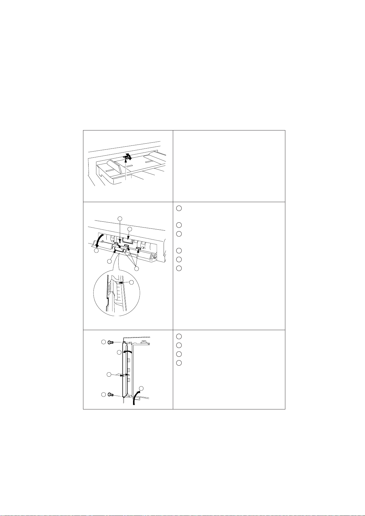
1
2
3
(For FP-7718/7722/7728/7735/7742/7750)
Upper Rear Cover
Check
Remove the original guide plate
of the copier.
Application of the anti-electrostatic liquid
(1)Clean the Plate glass before
application.
(2)
Apply (10cc) to a soft pad folded in half.
(3) Uniformly wipe the platen glass in
a lateral direction.
(4) Leave the platen glass for 10
minutes or longer, before handling.
Install the hinge positioning
screw.
(2 shoulder screws)
6-2
Upper Rear Cover
(For FP-D250/D350 Series)
SU001
Page 52

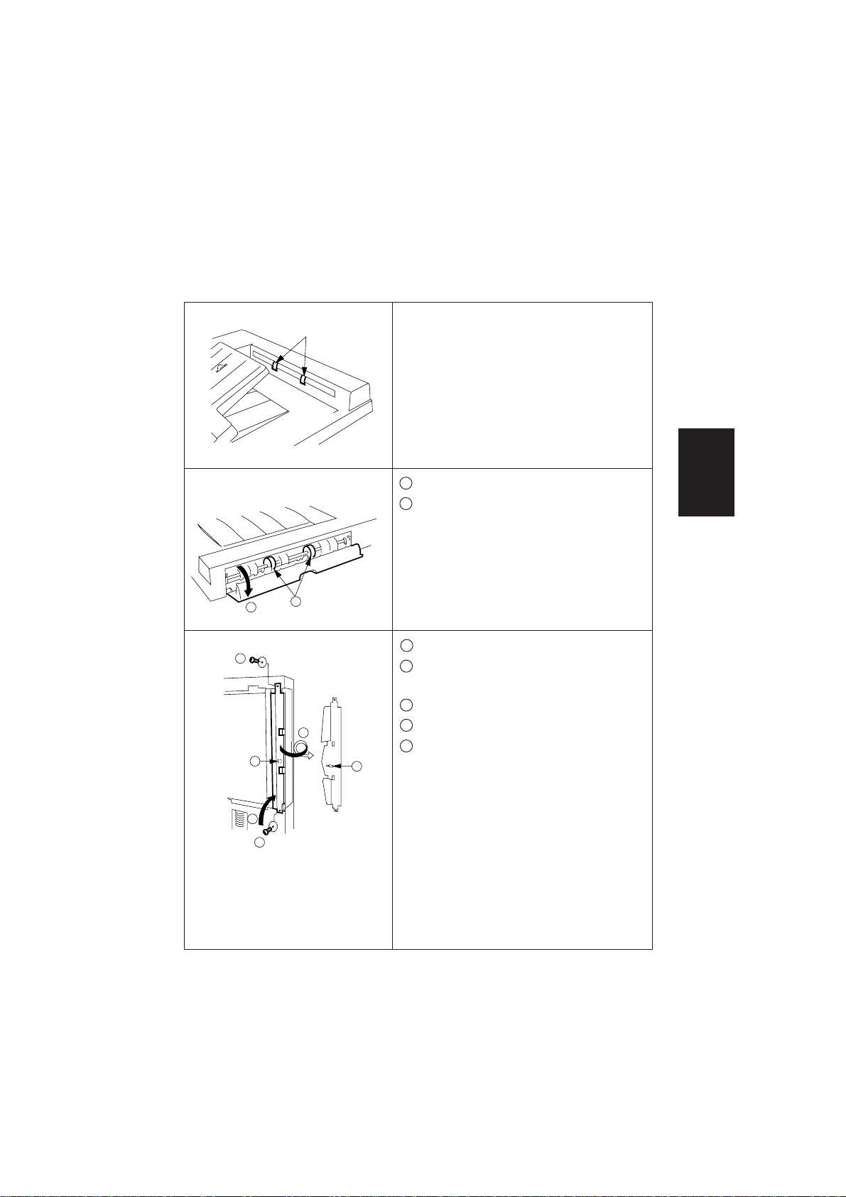
Location Shipping material / Procedure
4
3
8
6
7
2
1
(For FP-7718/7722/7728/7735/7742/7750)
3
4
6
6
6
5
Check
Installation of magenet catch plate.
(For FP-7718/7722/7728/7735/7742/7750)
(1) Remove right cover (upper).
(2) Remove the platen glass.
(3) Install the magnet catch plate to the
notches in the control panel.
(4) Reassemble in the reverse order.
Note:Use shorter screws to fix the
original guide plate.
(For FP-D250/D350 Series)
(1) Remove the top right cover.
(2 screws)
(2) Remove the original guide plate and
platen glass (2 screws)
(3) Install the magnet catch plates onto
the notches on the control panel.
(4) Reassemble in reverse order.
(For FP-D250/D350 Series)
5
Installation of ADF
(1) Place the ADF on the copier.
(2) Slide the hinges forward.
3
(The screws mentioned above fit
Installation
into the holes of both hinges.)
(3) Fix both hinges of the ADF by
2
1
1
Hinge
positioning
screw
SU002
tightening the hinge mounting
screws.
* Install the hinge positioning
screws at the center of the
hinge holes.
6-3
Page 53

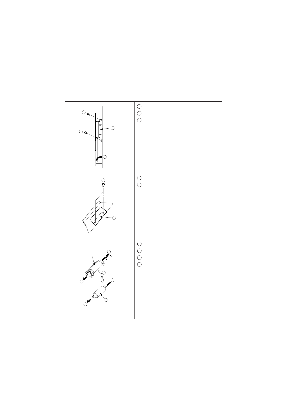
Location Shipping material / Procedure
6
2
Installation of Original Feed Tray.
(1) Connect the connector.
Check
(2)Install the original feed tray. (2
screws)
2
* Do not pinch the harness
when installing the original
1
SU003
feed tray.
7
Copier ADF Connector
8
Connect the ADF harness to the
copier ADF connector.
SU007
Change the position of the signal
harness of the CPU PCB.
Note: For the FP-D250/D350 series
(Digital copier), the following.
additional procedure must be
performed.
1
(1)Remove the blind plate from the
rear cover of the copier.
(2)Disconnect the harness from the
connector CN25 on the CPU PCB
and reconnect it to CN19 on the
CPU PCB.
2
(3) Reinstall rear cover.
6-4
Page 54

6.3 Adjustment
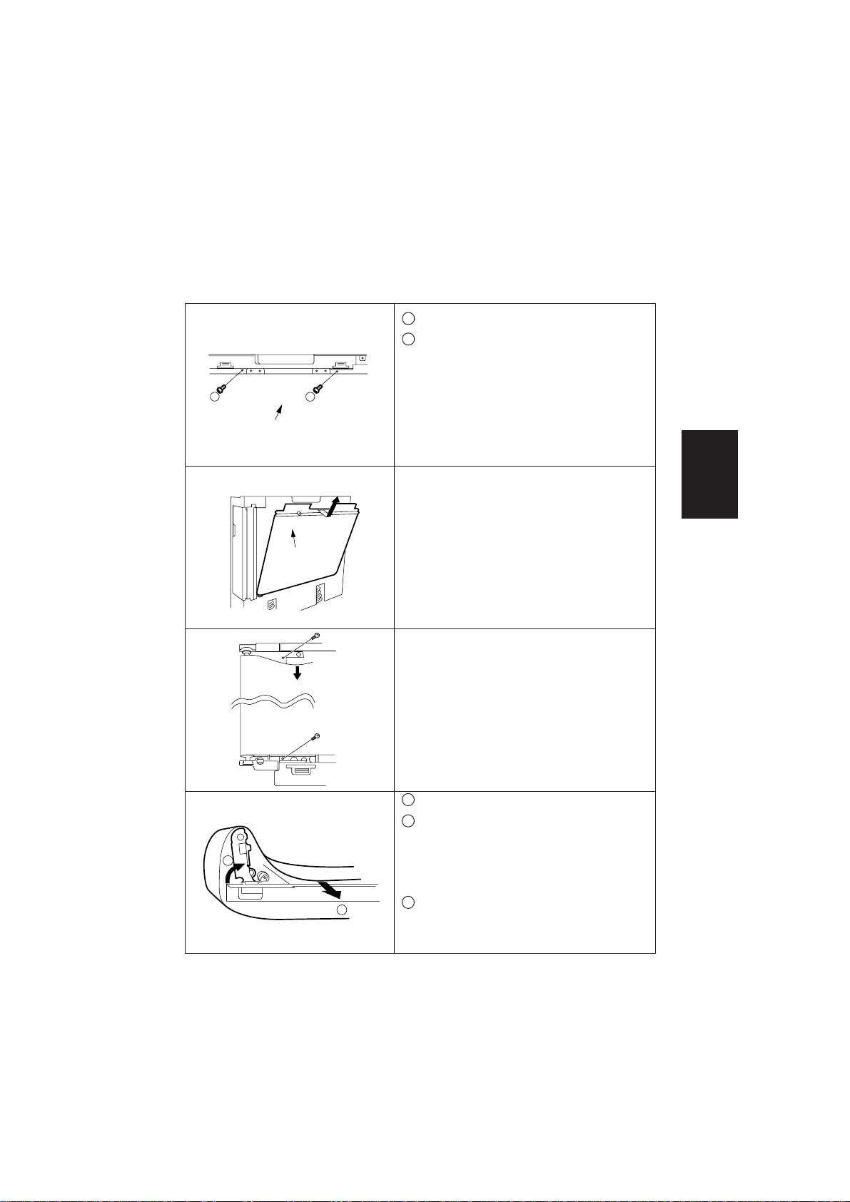
Location Shipping material /Procedure Check
1
2
Transport belt unit
Fixing screw
(Left side)
Platen Glass
Fixing screw
2
Rubber
spacer
Magnet
Magnet cartch
(Right side)
Rubber spacer
Height adjustment
Only required if the gap between the
platen glass and rubber spacer is over
0.5mm.
SV010
(See bottom figure)
a) Remove the top right cover of the
copier. (2 screws)
b) Remove the top left cover of the
copier. (2 screws)
c) Remove the original guide plate
of the copier. (3 screws)
(1) Remove the transport belt unit.
SV011
a)
Open the ADF to the service
position.
(90 degrees)
b) Remove the 2 screws on the
upper frame. (See top figure)
c) Remove the transport belt unit.
(2) Place the transport belt unit on the
platen glass. (See the figure on the
left)
Note:Make sure to align the
magnet with the magnet
catches.
(3) Loosen the fixing screws. (4 screws)
(4) Adjust the position of the magnets
so the gap between the platen glass
and the rubber spacer is less than
0.5mm.
(Right and left side)
(5) Reassemble in the reverse order.
(Left and right)
Installation
Magnet
Magnet cartch
SU009
6-5
Page 55

Location Shipping material / Procedure
2
11
2 2
SU005
Check
Original side to side adjustment
Note:Make sure the copier is
adjusted correctly before
making this adjustment.
(1) Loosen the original feed tray
adjusting screws (2 screws), and
move the tray front or rear as
required, then tighten the screws.
3
Hinge fixing screw
ADF hinge (Right)
A
B
Copy A
Copy B
Original skew adjustment
Note:Make sure the copier is
adjusted correctly before
making this adjustment.
(1) Open the ADF.
(2)Loosen the ADF hinge mounting
screw.
(Right side)
(3) Move the ADF in "A" or "B" direction
as required, then tighten the screw.
Copy A: Move the ADF in "A" direction.
Copy B: Move the ADF in "B" direction.
6-6
SU010
Page 56

Location Shipping material /Procedure Check
4
Original registration adjustment
(1)Press the "User Preset", "Ledger/
A3 of Original Size" and "3" keys
simultaneously to enter the F mode.
(2)Press the "6" key to enter the F6
mode.
(3)Press the "Print" key then "3" and
"6" key or "3" and "7" to enter the
required F6 code.
F6-36: Non-inverted original
F6-37: Inverted original
(4) Press the "Print" key.
(5) Enter the new content.
Note: The "Reset" key is used to
enter the "-" content.
(6) Press the "Print" key.
(7) Press the "User Preset" and "Clear/
Stop" keys simultaneously to
escape from the F mode.
(8)Place an original on the platen
glass.
(9)
Make a copy to confirm the adjustment.
5
1
1
ADF Open/Close position change
(1)Loosen the 4 screws securing the
stopper plate.
(2) Change the position of the screws
Installation
to upper position.
Upper: 65 degrees (In use)
2
2
65°
90°
SU006
Lower: 90 degrees (In service)
6-7
Page 57

Back to Model List
FA-A888 Parts Manual [Revised]
Contents/Index
1. Frame ................................................................................... AF1
2. Original Feed Section -1....................................................... AF2
3. Original Feed Section -2....................................................... AF3
4. Original Feed Section -3....................................................... AF4
5. Original Exit Section ............................................................. AF5
6. Transport Belt Section .......................................................... AF6
7. Numerical Parts Index .......................................................... AF7
Frame
Section -1
Original Feed
Section -2
Original Feed
Section -3
Original Feed
NOTE: For optimum machine performance, use recommended
Panasonic Parts.
Section
Original Exit
Section
Transport Belt
Numerical
Parts Index
Page 58

Use and Ordering Information
For USA
1. Information contained in this Parts manual is subject to change.
Change notices and supplementary pages will be issued on a timely basis.
2. Electrical parts supplied may include previously used components.
3. A Numerical Part Number List is located at the rear of this manual.
4. This manual was developed and is supplied to authorized servicing dealers by
Panasonic Document Imaging Company. for the sole purpose of providing
information necessary for the equipment's proper support. It is intended that this
information be confidential and may not be reproduced without prior written
consent from Panasonic Document Imaging Company.
5. Panasonic Document Imaging Company. reserves the right to change any
information enclosed herein without prior notification.
(This includes, but is not limited to, parts pricing and availability, and text.)
6. In common column, "C" indicates part is used in previous models, "N" indicates
part is used only in Model FA-A888.
7. Important safety notice
Components identified by
safety.
When replacing any of these components, use only manufacturer's specified
parts.
8. Rank column, "A, B, C, D," indicates the parts replacement frequency.
A: Most frequently used (PM parts)
B: Frequently used
C: Occasionally used
D: Hardly used
1. Information contained in this Parts manual is subject to change.
Change notices and supplementary pages will be issued on a timely basis.
2. Electrical parts supplied may include previously used components.
3. A Numerical Part Number List is located at the rear of this manual.
4. This manual was developed and is supplied to authorized servicing dealers by
Panasonic Co. for the sole purpose of providing information necessary for the
equipment's proper support. It is intended that this information be confidential
and may not be reproduced without prior written consent from Panasonic Co.
5. Panasonic Co. reserves the right to change any information enclosed herein
without prior notification.
(This includes, but is not limited to, parts pricing and availability, and text.)
6. In common column, "C" indicates part is used in previous models, "N" indicates
part is used only in Model FA-A888.
7. Important safety notice
Components identified by
safety.
When replacing any of these components, use only manufacturer's specified
parts.
8. Rank column, "A, B, C, D," indicates the parts replacement frequency.
A: Most frequently used (PM parts)
B: Frequently used
C: Occasionally used
D: Hardly used
mark have special characteristics important for
mark have special characteristics important for
Page 59

Frame
Frame
Back to Index
33
34
35
36
38
12
18
37
23
24
1
2
32
2
3
10
19
11
9
22
21
4
8
19
20
5
15
6
7
2
2
17
16
18
13
25
26
26
27
25
27
28
31
30
29
40
39
PM006
– AF1 –
Page 60

Frame
Ref.
No.
1 PF2217P133 Bracket, Connector 1 C D
2 E450000070 Nylon Clamp 4 C D
3 PF2217K205 TR1 Cable 1 C D
4 PF2217K207 SNR Cable 1 C D
5 PF2217K208 DRT-F Cable 1 C D
6 PF2217K202 CPU PCB (w/o ROM) 1 C C
7 PF2217K223 IF Cable 1 C D
8 PF2217K228 ROM 1 C C
9 PF2168P010 Tension Roller 1 C D
10 PF2217P378 Tension Spring 1 C C
11 PF2217K012 Tension Plate Ass’y 1 C D
12 PF2217K105 Transfer Motor Ass'y 1 C D
13 PF2217P364 Motor Cushion 1 C D
14 == Not used ==
15 PF2217P114 Lower Cover 1 C D
16 PF2217K007 Hinge Ass’y (Right) 1 C D
17 E450000433 Edge Saddle 1 C D
18 PF2214P513 Ground Spring 2 C D
19 PF2106P091 Shoulder Screw 2 C D
20 PF2164P306 Hinge Spring 1 C C
21 E120001165 Switch 1 C D
22 PF2217P130 Bracket, Switch 1 C D
23 PF2217K008 Hinge Ass’y (Left) 1 C D
24 PF2217P127 Switch Lever 1 C D
25 PF2217P135 Bracket, Transfer Belt 2 C D
26 PF2205P042 Paper Exit Pinch Roller 2 C D
27 PF2217P134 Pinch Roller Spring 2 C D
28 PF2217P001 Main Cover 1CD
29 PF2217P015 Maintenance Cover 1CD
30 660580 Nut 1 C C
31 PF2217P129 Cover Support Plate 1 C D
32 E450000748 Clamp 1 C D
33 PF2217K064 Original Feed Tray Ass’y (for PU) 1 C D
33 PF2217K065 Original Feed Tray Ass’y (for PG) 1 C D
34 PF2164P344 Catch Plate 2 C D
35 PF2217P303 Hinge Positioning Screw 2 C D
36 PF2217P319 Hinge Fixing Screw 2 C D
37 040080FNBI Orinal Feed Tray Mounting Screw 2 C D
38 PF2218K048 ADF Mounting Kit (No.33 to 37) 1 C D
39 PF2217P334 Label, Original Caution 1 C D
40 PF2217P336 Label, Jam Removal 1 C D
Part No. Description
Q'ty Per
Unit
Com-
mon
Rank
Frame
– AF1 –
Page 61

Original Feed Section -1
1
25
Back to Index
Section -1
Original Feed
13
2
3
7
10
8
14
9
8
15
26
16
17
24
4
5
11
12
18
17
11
5
22
22
A
21
23
A
20
19
14
13
6
PM001
– AF2 –
Page 62

Original Feed Section -1
Ref.
No.
1 PF2214P035 DFP Roller Pressure 1 C D
2 PF2214P344 Mylar 1 C D
3 PF2217P007 Paper Feed Cover 1CD
4 PF2217K103 DFP Roller Ass'y 1 C A
5 PF2214P303 Shoulder Screw 2 N D
6 PF2078P023 Shoulder Screw 1 N D
7 PF2214P034 Registration Roller Guide 1 C D
8 PF2214P379 Mylar 2 C D
9 PF2214P307 Reflection Seal 1 C D
10 PF2214P454 Mylar 1 C D
11 PF2214P022 Registration Roller Link 2 C D
12 PF2214P302 Registration Pinch Roller 1 C D
13 PF2214P312 Registration Spring 2 C C
14 690381 Bushing 2 C D
15 PF2217P100 Bracket Ass’y, Paper Feed (Front) 1 C D
16 PF2214P009 U Turn Guide 1 C D
17 PF2205P050 Registration Pinch Roller 2 C D
18 PF2214P458 Mylar 4 C D
19 PF2217K016 Bracket Ass’y, Paper Feed (Rear) 1 C D
20 PF2217P008 Paper Feed Exit Guide 1 C D
21 PF2217K214 SNS2 Cable 1 C D
22 PF2214K224 Sensor 2 C C
23 PF2217K224 FG-REG Cable 1 C D
24 PF2214B134 Bracket, Sensor 1 C D
25 PF2205P153 DFP Holder Stay 1 C D
26 PF2217P379 Rubber Spacer 1 C D
Part No. Description
Q'ty Per
Unit
Com-
mon
Rank
Section -1
Original Feed
– AF2 –
Page 63

Original Feed Section -2
Back to Index
10
9
Section -2
Original Feed
57
64
4
1
11
2
61
12
13
14
15
19
20
55
52
52
51
59
50
49
48
3
16
17
18
52
53
53
21
22
23
40
29
39
38
65
8
7
24
25
35
60
35
37
29
36
63
41
6
5
65
A
26
27
28
29
30
31
32
54
33
32
34
35
ADF2
No.25
58
A
59
62
28
63
47
46
64
45
44
35
43
42
35
PM002
– AF3-1 –
Page 64

Original Feed Section -2
Ref.
No.
1 PF2214P021 Weight Lever 1 C D
2 PF2214P313 Weight Spring 1 C D
3 PF2217P100 Bracket Ass’y, Paper Feed (Front) 1 C D
4 PF2214P132 DFP Stay 1 C D
5 PF2214P131 Bracket, Front DFP Plate 1 C D
6 PF2214P107 Front DFP Plate 1 C D
7 E314000528 Sensor 1 C C
8 PF2214P144 Bracket, Sensor 1 C D
9 338432 Bushing 1 C D
10 XPJ2D6WV Pin 1 C D
11 PF2129P188 Touch Ring 1 C D
12 PF2214P019 Weight Lever Shaft 1 C D
13 PF2160P018 Weight 1 C D
14 PF2217P354 Mylar 1 C D
15 PF2214P457 Cushion 1 C D
16 PF2214P020 Original Detecting Lever 1 C D
17 PF2214P007 DFP Guide 1 C D
18 PF2214P346 Mylar (Right) 1 C D
19 PF2214P345 Mylar (Left) 1 C D
20 PF2214P375 Mylar 1 C D
21 PF2214P342 Gear 30T 1 C D
22 338420 Bushing 1 C D
23 PF2176P307 Belt 72 1 C D
24 PF2142P037 Pulley 18T 1 C D
25 PF2217P201 Paper Feed Shaft 1 C D
26 PF2214P037 Cable Guide 1 C D
27 PF2217K224 FG-REG Cable 1 C D
28 PF2158P521 Bushing 2 C D
29 XPJ2D12WV Pin 3 C D
30 PF2198P003 Pulley 56T 1 C D
31 PF2217P314 Belt 164 1 C C
32 030080FPWP Clock Plate Screw 2 C D
33 PF2217P304 Clock Plate 1 C D
34 PF2214P109 Bracket, Sensor 1 C D
35 E450000897 Clamp 8 C D
36 PF2168P030 Pulley 50T 1 C D
37 PF2214P206 Shaft 2 1 C D
38 319300 Bushing 1 C D
39 PF2106P133 Paper Feed Motor 1 C D
40 PF2168P029 Gear 21T 1 C D
41 PF2217K016 Bracket Ass’y, Paper Feed (Rear) 1 C D
42 PF2214K033 Bracket, Idle Gear 1 C D
43 PF2217P309 Pulley 24T 1 C D
44 PF2217P310 Belt 272 1 C C
45 PF2214P318 Belt 120 1 C C
46 PF2214P306 Discharge Brush 1 C D
47 PF2217P010 Registration Roller Guide 1 C D
48 PF2198P302 Reflection Seal 1 C D
49 PF2214P376 Mylar 1 C D
50 PF2217P132 Bracket, Connector 1 C D
Part No. Description
Q'ty Per
Unit
Com-
mon
Rank
Section -2
Original Feed
– AF3-1 –
Page 65

Original Feed Section -2
Back to Index
10
9
Section -2
Original Feed
57
64
4
1
11
2
61
12
13
14
15
19
20
55
52
52
51
59
50
49
48
3
16
17
18
52
53
53
21
22
23
40
29
39
38
65
8
7
24
25
35
60
35
37
29
36
63
41
6
5
65
A
26
27
28
29
30
31
32
54
33
32
34
35
ADF2
No.25
58
A
59
62
28
63
47
46
64
45
44
35
43
42
35
PM002
– AF3-2 –
Page 66

Original Feed Section -2
Ref.
No.
51 PF2217K206 TR2 Cable 1 C D
52 PF2199P368 Cushion 4 C D
53 E450000574 Clamp 5 C D
54 E314000531 Sensor 1 C C
55 PF2214P343 Mylar 1 C D
56 == Not used ==
57 PF2217P009 Paper Feed Tray Guide 1 C D
58 PF2217K213 SNS1 Cable 1 C D
59 PF2214P405 SP Tube 2 C D
60 PF2217P121 Bracket, Paper Feed Motor 1 C D
61 PF2217K233 BLT-FG Cable 1 C D
62 E450000871 Cable Clamp 1 C D
63 PF2078P023 Shoulder Screw 2 C D
64 PF2078P086 Shoulder Screw 2 C D
65 600521 Shoulder Screw 2 C D
Part No. Description
Q'ty Per
Unit
Com-
mon
Rank
Section -2
Original Feed
– AF3-2 –
Page 67

Original Feed Section -3
Back to Index
Section -3
Original Feed
44
27
45
1
15
14
45
48
2
13
12
10
9
53
45
54
3
4
5
7
11
9
9
31
32
47
52
49
51
6
8
9
17
18
20
19
26
29
30
27
28
33
46
45
27
27
34
45
44
50
16
21
22
24
43
23
24
25
35
36
37
38
26
36
39
25
42
40
41
– AF4 –
PM003
Page 68

Original Feed Section -3
Ref.
No.
1 PF2164P348 Label, Indication (for North America) 1 C D
1 PF2164P349 Label, Indication (except North America) 1 C D
2 PF2217P019 Original Guide (Rear) 1 C D
3 PF2217P018 Original Guide (Front) 1 C D
4 PF2217P020 Original Feed Tray 1 C D
5 PF2217P340 Label, Original Size (for North America) 1 C D
5 PF2217P341
6 PF2164P123 Sensor Lever 1 C D
7 E314000531 Sensor 1 C C
8 PF2217K212 TRAY Cable 1 C D
9 E450000748 Cord Clamp 4 C D
10 PF2164P103 Rack 2 1 C D
11 PF2217P024 Rack 1 1 C D
12 PF2142P181 Gear Pressure 1 C D
13 PF2142P180 Gear 22T 1 C D
14 PF2164P219 Switch Stay 1 C D
15 PF2217K216 Original Width Detecting Switch 1 C D
16 PF2217P021 Original Feed Tray Lower Cover 1 C D
17 E120001165 Switch 1 C D
18 PF2217P122 Bracket, Switch 1 C D
19 PF2217K231 FGOD Cable 1 C D
20 PF2217P306 Switch Spring 1 C D
21 PF2217P123 Switch Cover 1 C D
22 PF2217P100 Bracket Ass’y, Paper Feed (Rear) 1 C D
23 PF2217P013 Switch Lever 1 C D
24 PF2214P455 Lock Spring 2 2 C D
25 E450000433 Edge Saddle 2 C D
26 319300 Bushing 2 C D
27 PF2158P521 Bushing 4 C D
28 PF2214P023 Stopper Lever 1 C D
29 PF2214P314 Shutter Spring 1 C D
30 E450000842 Edge Saddle 1 C D
31 PF2217P126 Bracket, Solenoid 1 C D
32 PF2217K084 Paper Feed Solenoid 1 C D
33 PF2217K227 DFSOL Cable 1 C D
34 PF2217K211 DR-F Cable 1 C D
35 E450000871 Cable Clamp 1 C D
36 XPJ2D12WV Pin 2 C D
37 PF2214P032 Gear 32T 1 C D
38 PF2217K016 Bracket Ass’y, Paper Feed (Front) 1 C D
39 PF2168P029 Gear 21T 1 C D
40 PF2214P317 Gear 32T 1 C D
41 PF2214P342 Gear 30T 1 C D
42 E450000897 Clamp 2 C D
43 PF2217K025 Belt Support Plate Ass’y 1 C D
44 PF2078P652 Bushing 2 C D
45 PF2088P034 Touch Ring 5 C D
46 PF2214P200 Paper Feed Shaft 1 C D
47 PF2095P310 Touch Ring 1 C D
48 PF2217P316 Paper Feed Roller 1 C A
49 PF2214P301 Registration Roller 1 C C
50 PF2078P023 Shoulder Screw 1 C D
51 PF2214P471 Pick-up Roller 1 C A
52 PF2214P201 Pick-up Roller Shaft 1 C D
53 XPJ2D14WV Pin 1 C D
54 PF2214P300 Original Stopper 1 C D
Part No. Description
Label, Original Size (except North America)
Q'ty Per
Com-
Unit
mon
1CD
Rank
Section -3
Original Feed
– AF4 –
Page 69

Original Exit Section
Back to Index
Section
Original Exit
1
2
3
4
A
5
14
9
6
7
8
20
30
32
39
60
66
59
58
31
10
11
12
13
50
65
19
68
33
38
62
61
15
14
16
2
17
34
35
32
37
67
23
22
25
26
69
27
25
70
28
18
29
36
63
6
16
40
26
24
41
21
55
64
54
52
52
57
56
53
54
57
53
A
65
2
20
43
42
49
47
46
48
47
44
45
PM005
– AF5-1 –
Page 70

Original Exit Section
Ref.
No.
1 PF2214P335 Reverse Lever Spring 1 C D
2 E450000842 Edge Saddle 3 C D
3 PF2217P131 Bracket, Solenoid 1 C D
4 PF2214P402 Reverse Solenoid 1 C D
5 PF2217K210 RU Cable 1 C D
6 XPJ2D10WV Pin 2 C D
7 PF2158P009 Link 2 1 C D
8 PF2158P005 Solenoid Stopper Pin 1 C D
9 PF2147P033 Link 1 1 C D
10 E120001165 Switch 1 C C
11 PF2217P124 Bracket, Switch 1 C D
12 PF2217P307 Switch Spring 1 C C
13 PF2217K209 DR-R Cable 1 C D
14 E450000005 Band 2 C D
15 PF2217P022 Cable Guide 1 C D
16 PF2158P521 Bushing 2 C D
17 PF2217P014 Switch Lever 1 C D
18 PF2217P125 Switch Cover 1 C D
19 PF2217K031 Bracket Ass’y, Paper Exit (Front) 1 C D
20 650593 Bearing 2 C D
21 PF2142P163 Lock Spring 1 1 C C
22 PF2214P143 Reverse Guide 2 1 C D
23 PF2217P152 Discharge Brush 1 C D
24 E450000574 Clamp 3 C D
25 PF2214P347 Rubber, Reverse Lever 2 C D
26 E450000871 Cable Clamp 6 C D
27 PF2214P323 Exit Roller 1 C C
28 PF2214P332 Reverse Lever 1 C D
29 PF2217P317 Reverse Roller 1 C D
30 PF2214P45 Mylar 1 C D
31 PF2106P091 Shoulder Screw 1 C D
32 PF2214P464 Mylar 2 C D
33 PF2214P046 Sensor Cover 1 C D
34 PF2214P381 Mylar 1 C D
35 PF2214P460 Mylar 1 C D
36 PF2214P465 Mylar 1 C D
37 PF2214P466 Mylar 1 C D
38 PF2214P012 Reverse Lower Guide 1 C D
39 PF2214K222 Reverse Sensor 1 C C
40 PF2217P025 Pulley 17T 1 C D
41 PF2217K049 Bracket Ass’y, Paper Exit (Rear) 1 C D
42 XPJ2D12WV Pin 1 C D
43 PF2214P146 Flange 1 C D
44 PF2142P141 Pulley 30T 1 C D
45 PF2217K106 Reverse Motor Ass'y 1 C D
46 PF2214P348 Pulley 23T/32T 1 C D
47 040080FPWP Pulley 23T/32T Screw 2 C D
48 PF2094P090 Belt 88 1 C D
49 PF2107P032 Belt 56 1 C D
50 PF2214P455 Lock Spring 2 1 C D
Part No. Description
Q'ty Per
Unit
Com-
mon
Rank
Section
Original Exit
– AF5-1 –
Page 71

Original Exit Section
Back to Index
Section
Original Exit
1
2
3
4
A
5
14
9
6
7
8
20
30
32
39
60
66
59
58
31
10
11
12
13
50
65
19
68
33
38
62
61
15
14
16
2
17
34
35
32
37
67
23
22
25
26
69
27
25
70
28
18
29
36
63
6
16
40
26
24
41
21
55
64
54
52
52
57
56
53
54
57
53
A
65
2
20
43
42
49
47
46
48
47
44
45
PM005
– AF5-2 –
Page 72

Original Exit Section
Ref.
No.
51 == Not used ==
52 PF2214P387 Mylar 2 C D
53 PF2214P033 Reverse Pinch Roller 2 C D
54 PF2214P209 Pinch Roller Shaft 2 C D
55 PF2217K035 Reverse Leaf Spring 2 C D
56 PF2217P004 Paper Exit Cover 1CD
57 PF2214P124 Leaf Spring, Reverse Pinch Roller 4 C D
58 PF2217P111 Reverse Support Guide 1 C D
59 PF2217P005 Reverse Lower Guide 1 C D
60 PF2217P308 Mylar 1 C D
61 PF2214P352 Reflection Seal 1 C D
62 PF2214P383 Mylar 1 C D
63 E450000896 Clamp 1 C D
64 PF2199P367 DPP Cushion 1 C D
65 PF2078P023 Shoulder Screw 2 C D
66 PF2217K233 BLT-FG Cable 1 C D
67 PF2078P086 Shoulder Screw 2 C D
68 PF2217P379 Rubber Spacer 1 C D
69 PF2217P355 R Guide 2, Mylar F 1 C D
70 PF2217P356 R Guide 2, Mylar R 1 C D
Part No. Description
Q'ty Per
Unit
Com-
mon
Rank
– AF5-2 –
Section
Original Exit
Page 73

Transport Belt Section
1
2
4
5
7
9
10
8
24
17
16
Back to Index
2
3
3
7
6
2
3
9
11
10
8
1
2
17
3
18
2
14
13
12
2
3
14
13
12
16
7
1
15
16
3
Section
Transport Belt
23
22
21
7
20
4
16
25
19
PM004
– AF6 –
Page 74

Transport Belt Section
Ref.
No.
1 PF2214P118 Belt Stay 3 C D
2 PF2158P035 Pressure Pinch Roller 6 C D
3 PF2214P141 Pinch Roller Leaf Spring 6 C D
4 PF2214P353 Transport Belt 2 C A
5 PF2214P322 Belt Roller(Left) 1 C D
6 PF2217P202 Roller 1 C D
7 650593 Bearing 4 C D
8 PF2217P002 Roller Holder 2 C D
9 PF2164P142 Spring Holder 2 C D
10 PF2217P302 Roller Spring 2 C C
11 PF2217P103 Bracket, Transport Belt (Front) 1 C D
12 PF2217P312 Spacer Rubber 2 C D
13 PF2217P102 Bracket, Magnet Catch 2 C D
14 PF2214P393 Magnet Catch 2 C D
15 PF2217P105 Tension Plate (Front) 1 C D
16 PF2205P037 Pressure Holder 4 C D
17 PF2205P014 Belt Guide 2 C D
18 PF2217P329 Belt Pressure Roller 2 1 C D
19 PF2217P311 Transfer Belt Roller (Right) 1 C D
20 PF2217P328 Belt Pressure Roller 4 1 C D
21 PF2217P106 Tension Plate (Rear) 1 C D
22 PF2217P104 Bracket, Transport Belt (Rear) 1 C D
23 PF2185P023 Pulley 30T 1 C D
24 PF2164P136 Glass Spacer 1 C D
25 PF2217P011 Glass Spacer 1 C D
Part No. Description
Q'ty Per
Unit
Com-
mon
Rank
– AF6 –
Section
Transport Belt
Page 75

Numerical
Parts Index
Numerical Parts Index
Q'ty Per
Ref.
Part No.
319300 Bushing AF3 38 1
319300 Bushing AF4 26 2
338420 Bushing AF3 22 1
338432 Bushing AF3 9 1
600521 Shoulder Screw AF3 65 2
650593 Bearing AF5 20 2
650593 Bearing AF6 7 4
660580 Nut AF1 30 1
690381 Bushing AF2 14 2
030080FPWP Clock Plate Screw AF3 32 2
040080FNBI Orinal Feed Tray Mounting Screw AF1 37 2
040080FPWP Pulley 23T/32T Screw AF5 47 2
E120001165 Switch AF4 17 1
E120001165 Switch AF1 21 1
E120001165 Switch AF5 10 1
E314000528 Sensor AF3 7 1
E314000531 Sensor AF3 54 1
E314000531 Sensor AF4 7 1
E450000005 Band AF5 14 2
E450000070 Nylon Clamp AF1 2 4
E450000433 Edge Saddle AF1 17 1
E450000433 Edge Saddle AF4 25 2
E450000574 Clamp AF3 53 5
E450000574 Clamp AF5 24 3
E450000748 Clamp AF1 32 1
E450000748 Cord Clamp AF4 9 4
E450000842 Edge Saddle AF4 30 1
E450000842 Edge Saddle AF5 2 2
E450000871 Cable Clamp AF3 62 1
E450000871 Cable Clamp AF4 35 1
E450000871 Cable Clamp AF5 26 6
E450000896 Clamp AF5 63 1
E450000897 Clamp AF3 35 8
E450000897 Clamp AF4 42 2
PF2078P023 Shoulder Screw AF2 6 1
PF2078P023 Shoulder Screw AF3 63 2
PF2078P023 Shoulder Screw AF4 50 1
PF2078P023 Shoulder Screw AF5 65 2
PF2078P086 Shoulder Screw AF3 64 2
PF2078P086 Shoulder Screw AF5 67 2
PF2078P652 Bushing AF4 44 2
PF2088P034 Touch Ring AF4 45 5
PF2094P090 Belt 88 AF5 48 1
PF2095P310 Touch Ring AF4 47 1
PF2106P091 Shoulder Screw AF1 19 2
PF2106P091 Shoulder Screw AF5 31 1
PF2106P133 Paper Feed Motor AF3 39 1
PF2107P032 Belt 56 AF5 49 1
PF2119P200 Plate Support AF2 26 1
Description
Page
No.
No.
Unit
– AF7 –
Page 76

Numerical Parts Index
Q'ty Per
No.
Ref.
No.
Unit
Part No.
PF2119P200 Plate Support AF5 68 1
PF2129P188 Touch Ring AF3 11 1
PF2142P037 Pulley 18T AF3 24 1
PF2142P141 Pulley 30T AF5 44 1
PF2142P163 Lock Spring 1 AF5 21 1
PF2142P180 Gear 22T AF4 13 1
PF2142P181 Gear Pressure AF4 12 1
PF2147P033 Link 1 AF5 9 1
PF2158P005 Solenoid Stopper Pin AF5 8 1
PF2158P009 Link 2 AF5 7 1
PF2158P035 Pressure Pinch Roller AF6 2 6
PF2158P521 Bushing AF3 28 2
PF2158P521 Bushing AF4 27 4
PF2158P521 Bushing AF5 16 2
PF2160P018 Weight AF3 13 1
PF2164P103 Rack 2 AF4 10 1
PF2164P123 Sensor Lever AF4 6 1
PF2164P136 Glass Spacer AF6 24 1
PF2164P142 Spring Holder AF6 9 2
PF2164P219 Switch Stay AF4 14 1
PF2164P306 Hinge Spring AF1 20 1
PF2164P344 Catch Plate AF1 34 2
PF2164P348 Label, Indication (for North America) AF4 1 1
PF2164P349 Label, Indication (except North America) AF4 1 1
PF2168P010 Tension Roller AF1 9 1
PF2168P029 Gear 21T AF3 40 1
PF2168P029 Gear 21T AF4 39 1
PF2168P030 Pulley 50T AF3 36 1
PF2176P307 Belt 72 AF3 23 1
PF2185P023 Pulley 30T AF6 23 1
PF2198P003 Pulley 56T AF3 30 1
PF2198P302 Reflection Seal AF3 48 1
PF2199P367 DPP Cushion AF5 64 1
PF2199P368 Cushion AF3 52 4
PF2205P014 Belt Guide AF6 17 2
PF2205P037 Pressure Holder AF6 16 4
PF2205P042 Paper Exit Pinch Roller AF1 26 2
PF2205P050 Registration Pinch Roller AF2 17 2
PF2205P153 DFP Holder Stay AF2 25 1
PF2214B134 Bracket, Sensor AF2 24 1
PF2214K033 Bracket, Idle Gear AF3 42 1
PF2214K222 Reverse Sensor AF5 39 1
PF2214K224 Sensor AF2 22 2
PF2214P007 DFP Guide AF3 17 1
PF2214P009 U Turn Guide AF2 16 1
PF2214P012 Reverse Lower Guide AF5 38 1
PF2214P019 Weight Lever Shaft AF3 12 1
PF2214P020 Original Detecting Lever AF3 16 1
PF2214P021 Weight Lever AF3 1 1
Description
Page
Numerical
Parts Index
– AF8 –
Page 77

Numerical
Parts Index
Numerical Parts Index
Q'ty Per
No.
Ref.
No.
Unit
Part No.
PF2214P022 Registration Roller Link AF2 11 2
PF2214P023 Stopper Lever AF4 28 1
PF2214P032 Gear 32T AF4 37 1
PF2214P033 Reverse Pinch Roller AF5 53 2
PF2214P034 Registration Roller Guide AF2 7 1
PF2214P035 DFP Roller Pressure AF2 1 1
PF2214P037 Cable Guide AF3 26 1
PF2214P046 Sensor Cover AF5 33 1
PF2214P107 Front DFP Plate AF3 6 1
PF2214P109 Bracket, Sensor AF3 34 1
PF2214P118 Belt Stay AF6 1 3
PF2214P124 Leaf Spring, Reverse Pinch Roller AF5 57 4
PF2214P131 Bracket, Front DFP Plate AF3 5 1
PF2214P132 DFP Stay AF3 4 1
PF2214P141 Pinch Roller Leaf Spring AF6 3 6
PF2214P143 Reverse Guide 2 AF5 22 1
PF2214P144 Bracket, Sensor AF3 8 1
PF2214P146 Flange AF5 43 1
PF2214P200 Paper Feed Shaft AF4 46 1
PF2214P201 Pick-up Roller Shaft AF4 52 1
PF2214P206 Shaft 2 AF3 37 1
PF2214P209 Pinch Roller Shaft AF5 54 2
PF2214P300 Original Stopper AF4 54 1
PF2214P301 Registration Roller AF4 49 1
PF2214P302 Registration Pinch Roller AF2 12 1
PF2214P303 Shoulder Screw AF2 5 2
PF2214P306 Discharge Brush AF3 46 1
PF2214P307 Reflection Seal AF2 9 1
PF2214P312 Registration Spring AF2 13 2
PF2214P313 Weight Spring AF3 2 1
PF2214P314 Shutter Spring AF4 29 1
PF2214P317 Gear 32T AF4 40 1
PF2214P318 Belt 120 AF3 45 1
PF2214P322 Belt Roller(Left) AF6 5 1
PF2214P323 Exit Roller AF5 27 1
PF2214P332 Reverse Lever AF5 28 1
PF2214P335 Reverse Lever Spring AF5 1 1
PF2214P342 Gear 30T AF3 21 1
PF2214P342 Gear 30T AF4 41 1
PF2214P343 Mylar AF3 55 1
PF2214P344 Mylar AF2 2 1
PF2214P345 Mylar (Left) AF3 19 1
PF2214P346 Mylar (Right) AF3 18 1
PF2214P347 Rubber, Reverse Lever AF5 25 2
PF2214P348 Pulley 23T/32T AF5 46 1
PF2214P350 Tension Spring AF1 10 1
PF2214P352 Reflection Seal AF5 61 1
PF2214P353 Transport Belt AF6 4 2
PF2214P375 Mylar AF3 20 1
Description
Page
– AF9 –
Page 78

Numerical Parts Index
Q'ty Per
No.
Ref.
No.
Unit
Part No.
PF2214P376 Mylar AF3 49 1
PF2214P379 Mylar AF2 8 2
PF2214P381 Mylar AF5 34 1
PF2214P383 Mylar AF5 62 1
PF2214P387 Mylar AF5 52 2
PF2214P393 Magnet Catch AF6 14 2
PF2214P402 Reverse Solenoid AF5 4 1
PF2214P405 SP Tube AF3 59 2
PF2214P45 Mylar AF5 30 1
PF2214P454 Mylar AF2 10 1
PF2214P455 Lock Spring 2 AF4 24 2
PF2214P455 Lock Spring 2 AF5 50 1
PF2214P457 Cushion AF3 15 1
PF2214P458 Mylar AF2 18 4
PF2214P460 Mylar AF5 35 1
PF2214P464 Mylar AF5 32 2
PF2214P465 Mylar AF5 36 1
PF2214P466 Mylar AF5 37 1
PF2214P471 Pick-up Roller AF4 51 1
PF2214P513 Ground Spring AF1 18 2
PF2217K212 TRAY Cable AF4 8 1
PF2217K007 Hinge Ass’y (Right) AF1 16 1
PF2217K008 Hinge Ass’y (Left) AF1 23 1
PF2217K012 Tension Plate Ass’y AF1 11 1
PF2217K016 Bracket Ass’y, Paper Feed (Rear) AF2 19 1
PF2217K016 Bracket Ass’y, Paper Feed (Rear) AF3 41 1
PF2217K016 Bracket Ass’y, Paper Feed (Front) AF4 38 1
PF2217K025 Belt Support Plate Ass’y AF4 43 1
PF2217K031 Bracket Ass’y, Paper Exit (Front) AF5 19 1
PF2217K035 Reverse Leaf Spring AF5 55 2
PF2217K049 Bracket Ass’y, Paper Exit (Rear) AF5 41 1
PF2217K064 Original Feed Tray Ass’y (for PU) AF1 33 1
PF2217K065 Original Feed Tray Ass’y (for PG) AF1 33 1
PF2217K084 Paper Feed Solenoid AF4 32 1
PF2217K105 Transfer Motor Ass'y AF1 12 1
PF2217K106 Reverse Motor Ass'y AF5 45 1
PF2217K103 DFP Roller Ass’y AF2 4 1
PF2217K202 CPU PCB(w/o ROM) AF1 6 1
PF2217K205 TR1 Cable AF1 3 1
PF2217K206 TR2 Cable AF3 51 1
PF2217K207 SNR Cable AF1 4 1
PF2217K208 DRT-F Cable AF1 5 1
PF2217K209 DR-R Cable AF5 13 1
PF2217K210 RU Cable AF5 5 1
PF2217K211 DR-F Cable AF4 34 1
PF2217K213 SNS1 Cable AF3 58 1
PF2217K214 SNS2 Cable AF2 21 1
PF2217K216 Original Width Detecting Switch AF4 15 1
PF2217K223 IF Cable AF1 7 1
Description
Page
Numerical
Parts Index
– AF10 –
Page 79

Numerical
Parts Index
Numerical Parts Index
Q'ty Per
No.
Ref.
No.
Unit
Part No.
PF2217K224 FG-REG Cable AF2 23 1
PF2217K224 FG-REG Cable AF3 27 1
PF2217K227 DFSOL Cable AF4 33 1
PF2217K228 ROM AF1 8 1
PF2217K231 FGOD Cable AF4 19 1
PF2217K233 BLT-FG Cable AF3 61 1
PF2217K233 BLT-FG Cable AF5 66 1
PF2217P001 Main Cover AF1 28 1
PF2217P002 Roller Holder AF6 8 2
PF2217P004 Paper Exit Cover AF5 56 1
PF2217P005 Reverse Lower Guide AF5 59 1
PF2217P007 Paper Feed Cover AF2 3 1
PF2217P008 Paper Feed Exit Guide AF2 20 1
PF2217P009 Paper Feed Tray Guide AF3 57 1
PF2217P010 Registration Roller Guide AF3 47 1
PF2217P011 Glass Spacer AF6 25 1
PF2217P013 Switch Lever AF4 23 1
PF2217P014 Switch Lever AF5 17 1
PF2217P015 Maintenance Cover AF1 29 1
PF2217P018 Original Guide (Front) AF4 3 1
PF2217P019 Original Guide (Rear) AF4 2 1
PF2217P020 Original Feed Tray AF4 4 1
PF2217P021 Original Feed Tray Lower Cover AF4 16 1
PF2217P022 Cable Guide AF5 15 1
PF2217P024 Rack 1 AF4 11 1
PF2217P025 Pulley 17T AF5 40 1
PF2217P100 Bracket Ass’y, Paper Feed (Front) AF2 15 1
PF2217P100 Bracket Ass’y, Paper Feed (Front) AF3 3 1
PF2217P100 Bracket Ass’y, Paper Feed (Rear) AF4 22 1
PF2217P102 Bracket, Magnet Catch AF6 13 2
PF2217P103 Bracket, Transport Belt (Front) AF6 11 1
PF2217P104 Bracket, Transport Belt (Rear) AF6 22 1
PF2217P105 Tension Plate (Front) AF6 15 1
PF2217P106 Tension Plate (Rear) AF6 21 1
PF2217P111 Reverse Support Guide AF5 58 1
PF2217P112 Bracket, Reverse Motor AF5 51 1
PF2217P114 Lower Cover AF1 15 1
PF2217P121 Bracket, Paper Feed Motor AF3 60 1
PF2217P122 Bracket, Switch AF4 18 1
PF2217P123 Switch Cover AF4 21 1
PF2217P124 Bracket, Switch AF5 11 1
PF2217P125 Switch Cover AF5 18 1
PF2217P126 Bracket, Solenoid AF4 31 1
PF2217P127 Switch Lever AF1 24 1
PF2217P129 Cover Support Plate AF1 31 1
PF2217P130 Bracket, Switch AF1 22 1
PF2217P131 Bracket, Solenoid AF5 3 1
PF2217P132 Bracket, Connector AF3 50 1
PF2217P133 Bracket, Connector AF1 1 1
Description
Page
– AF11 –
Page 80

Numerical Parts Index
Q'ty Per
No.
Ref.
No.
Unit
Part No.
PF2217P134 Pinch Roller Spring AF1 27 2
PF2217P135 Bracket, Transfer Belt AF1 25 2
PF2217P152 Discharge Brush AF5 23 1
PF2217P201 Paper Feed Shaft AF3 25 1
PF2217P202 Roller AF6 6 1
PF2217P302 Roller Spring AF6 10 2
PF2217P303 Hinge Positioning Screw AF1 35 2
PF2217P304 Clock Plate AF3 33 1
PF2217P306 Switch Spring AF4 20 1
PF2217P307 Switch Spring AF5 12 1
PF2217P308 Mylar AF5 60 1
PF2217P309 Pulley 24T AF3 43 1
PF2217P310 Belt 272 AF3 44 1
PF2217P311 Transfer Belt Roller (Right) AF6 19 1
PF2217P312 Spacer Rubber AF6 12 2
PF2217P314 Belt 164 AF3 31 1
PF2217P316 Paper Feed Roller AF4 48 1
PF2217P317 Reverse Roller AF5 29 1
PF2217P319 Hinge Fixing Screw AF1 36 2
PF2217P328 Belt Pressure Roller 4 AF6 20 1
PF2217P329 Belt Pressure Roller 2 AF6 18 1
PF2217P334 Label, Original Caution AF1 39 1
PF2217P336 Label, Jam Removal AF1 40 1
PF2217P340 Label, Original Size (for North America) AF4 5 1
PF2217P341 Label, Original Size (except North America) AF4 5 1
PF2217P354 Mylar AF3 14 1
PF2217P355 R Guide 2, Mylar F AF5 69 1
PF2217P356 R Guide 2, Mylar R AF5 70 1
PF2217P364 Motor Cushion AF1 13 1
PF2217P379 Rubber Spacer AF2 30 1
PF2218K048 ADFMounting Kit (No.33 to 37) AF1 38 1
XPJ2D10WV Pin AF5 6 2
XPJ2D12WV Pin AF3 29 3
XPJ2D12WV Pin AF4 36 2
XPJ2D12WV Pin AF5 42 1
XPJ2D14WV Pin AF4 53 1
XPJ2D6WV Pin AF3 10 1
Description
Page
– AF12 –
Numerical
Parts Index
Page 81

 Loading...