

Panasonic FA-A355 User Manual

FA-A355
Contents/Index
WARNING
I. Introduction
1.1 Specifications.......................................................................................... 1-1
1.2 Features.................................................................................................. 1-1
1.3 Exterior ................................................................................................... 1-2
1.4 Interior..................................................................................................... 1-2
II. Operation
2.1 Normal feeding (copy) ............................................................................ 2-1
III. Maintenance
3.1 Maintenance chart .................................................................................. 3-1
3.2 Cleaning.................................................................................................. 3-1
3.3 Disassembly/Assembly........................................................................... 3-2
IV. Electrical
4.1 Signal information by connector ............................................................. 4-1
4.2 Explanation of circuit............................................................................... 4-6
V. Troubleshooting
5.1 Error detection by self-diagnostics.......................................................... 5-1
5.2 Service mode.......................................................................................... 5-3
VI. Installation
6.1 Installation requirements......................................................................... 6-1
6.2 Unpacking............................................................................................... 6-2
6.3 Installation procedure ............................................................................. 6-3
6.4 Adjustment.............................................................................................. 6-6
ADF Driver PCB
Electrical Maintenance Operation Introduction
Installation
Troubleshooting
FA-A355 Back to Model List

WARNING
This service information is designed for experienced repair technicians only and
is not designed for use by the general public.
It does not contain warnings or cautions to advise non-technical individuals of
potential dangers in attempting to service a product.
Products powered by electricity should be serviced or repaired only by experienced
professional technicians. Any attempt to service or repair the product or products
dealt with in this service information by anyone else could result serious injury or
death.
(For USA)
This manual was developed and is supplied to authorized servicing dealers by
Panasonic Communications & Systems Co. for the sole purpose of providing
information necessary for the equipment's proper support. It is intended that this
information be confidential and may not be reproduced without prior written consent
from Panasonic Communications & Systems Co. Panasonic Communications &
Systems Co. reserves the right to change any information enclosed herein without
prior notification.
© February, 1999
This manual was developed and is supplied to authorized servicing dealers by
Panasonic Co. for the sole purpose of providing information necessary for the
equipment's proper support. It is intended that this information be confidential
and may not be reproduced without prior written consent from Panasonic Co.
Panasonic Co. reserves the right to change any information enclosed herein without
prior notification.

1-1
Introduction
1. For use with: FP-D250/D350 Series
2. Original paper capacity: 50 sheets (20 lb/80 g/m
2
)
30 sheets (20 lb/80 g/m2) Ledger, Legal/A3,B4
3. Original size: Ledger to Invoice/A3 to A5
4. Original paper weight: 14 to 28 lb/50 to 110 g/m
2
5. Original feed speed: 35 sheets/min.
6. Power source: DC +24V (Supplied from copier)
7. Dimensions (W x H x D): 24.5" x 21.5" x 4.6"/622 x 546 x 117 mm
(without tray)
8. Weight: 24.2 lb/11 kg
9. Ambient conditions: Temperature 50˚F to 86˚F/10˚C to 30˚C
Relative humidity 30 to 80%
1.2 Features
• Original size feeding system
• Originals of different size but with the same width (Ledger/Letter, A3/A4) can be
combined for feeding.
• Original size detection system
• By placing the originals onto the tray, original size can be detected automatically.
• Realization of space saving
• Power unit is installed in the copier, so the document feeder is physically smaller.
• Capable of feeding originals up to Ledger/A3 size.
Section I Introduction
1.1 Specifications

1-2
1.3 Exterior
1.4 Interior
Original guides
Original exit cover
Original exit tray
ADF driver PCB
Door open/close sensor
Original pick up solenoid
Transport motor
ADF open/close sensor
Original feed motor
Paper exit deceleration
clutch
Original exit sensor 2
Original exit
sensor 1
Paper exit
switching solenoid
Registration
sensor
Original detecting
sensor
Original size detecting sensor
2-1
Operation
1
Section II Operation
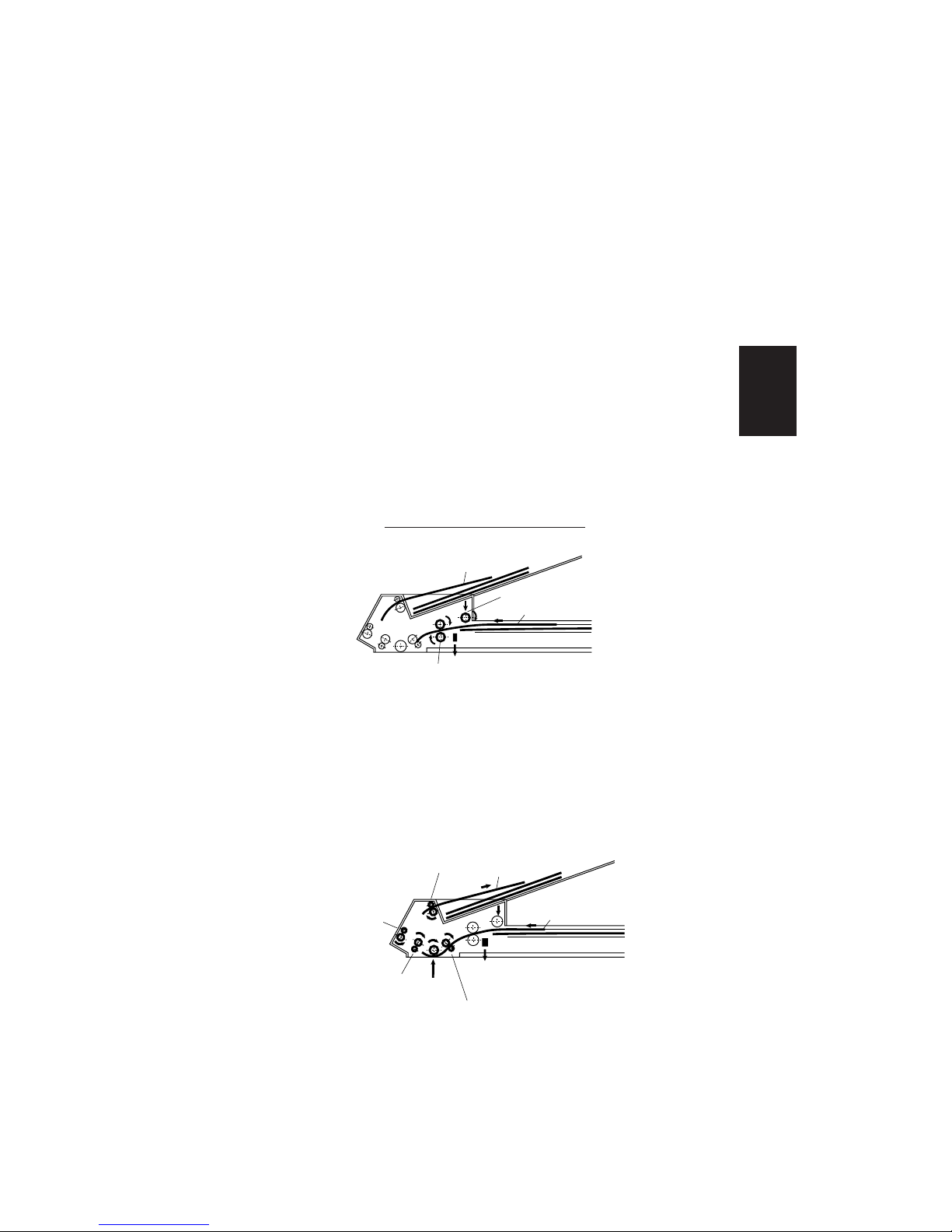
2.1 Normal feeding (copy)
• Original feeding begins with the last page.
(1) When the start button is pressed, the paper feed motor and pick-up solenoid
are energized. The pick-up roller moves down towards the stack of originals
and transports the original on the top of the stack to the paper feed roller. The
entrance gate is opened and the paper feed roller rotates to feed the original to
the registration roller. Double feed prevention is provided by the lower paper
feed/double feed prevention roller.
The paper feed motor stops a predetermined time after the lead edge of the
original passes by the registration sensor. The original is held in place by the
resistration roller.
(2) The transport motor is energized and the registration roller begins to rotate.
The original is then transported to the original holding roller.
The original is scanned as it passes between the original holding roller and the
platen glass.
The paper exit switching solenoid is then energized and the paper exit-switching
claw is switched to the upper paper discharge position.
After the trail edge of the original passes by the original holding roller, the
transport motor stops.
Normal feeding (copy)
Fed from the last page of originals
3 (STOP)
4
5
Pick-up roller
Paper feed roller
Double feed prevention roller
Paper exit roller C
Paper exit roller F
Transport roller
Optical
Registration roller
2
2
3
4
5
1

2-2
(3) The paper feed motor and pick-up solenoid are energized again. The pick-up
roller moves down towards the stack of originals and the next original is fed.
The paper exit rollers rotate to discharge the original. During paper discharge
the deceleration clutch is released to ensure that the paper is neatly stacked in
the exit tray.
Paper exit roller C
Paper exit roller F
Transport roller
Paper feed roller
Double feed prevention roller
Registration roller
Pick-up roller
Optical
2
3
4
5
3-1
Maintenance
Cleaning
Replacement
Section III Maintenance
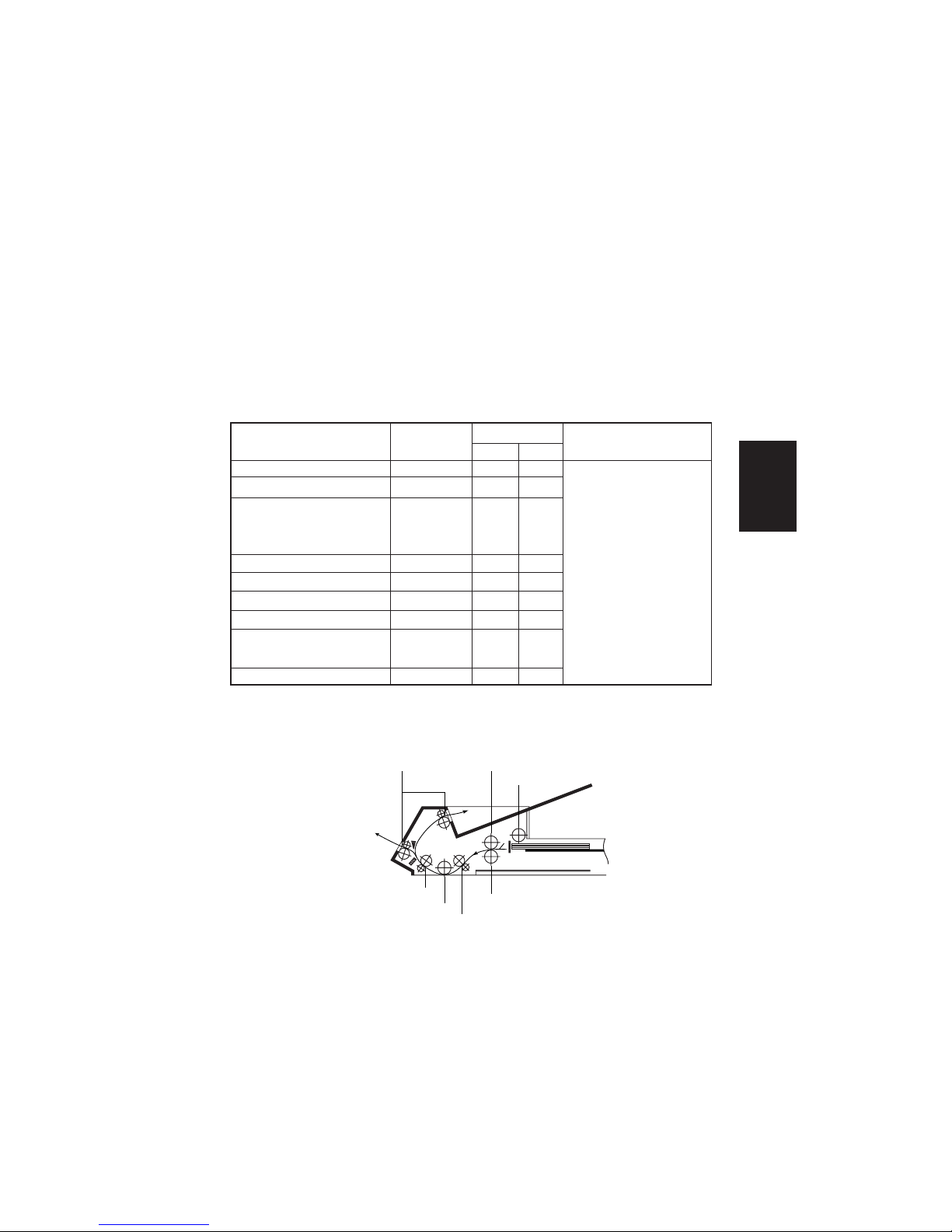
3.1 Maintenance chart
• In addition to the following maintenance table, the platen mat must be cleaned as
part of regular service calls.
• The timing of regular maintenance is determined on the basis of the number of
ADF original feed count. (F7-06)
Original feed roller/DFP roller
Original pick-up roller
Original detecting sensor
Registration sensor
Original exit sensor
Original support roller
Transport roller
Registration roller (upper)
Registration roller (lower)
Original exit roller (left)
(right)
Torque limiter spring
FFPMA0604
FFPMA0605
GP1A73A
FFPMA0609
FFPMA0607
FFPMA0606
FFPMA0608
FFPMA0602
FFPMA0603
FFPLR0287
Brush, air blower,
isopropyl alcohol (IPA)
Note: •Rollers should be
cleaned with water
and cloth.
•Use of IPA
(Isopropyl alcohol)
should be used
sparingly.
Part name
Part number
Remarks
3.2 Cleaning
Clean each rollers.
Maintenance interval
120,000
120,000
–––
–––
–––
–––
–––
–––
(Lubrication)
Exit roller Original feed roller
Pick-up roller
Registration roller
Transport roller
Original support roller
60,000
60,000
120,000
60,000
60,000
60,000
60,000
60,000
120,000
DFP roller (lower)
3-2
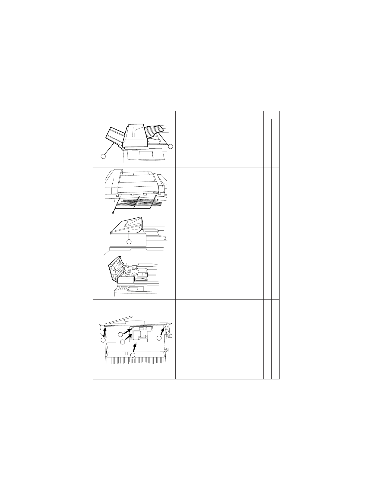
3.3 Disassembly/Assembly
Location Procedure
Check
1
2
(1) Remove the original catch tray 1.
(2) Remove the original catch tray 2.
(FA-F350)
(1) Remove the left side cover (3
screws).
3
(1) Open up the paper feed section.
(2) Remove the stopper (1 shoulder
screw).
Note: Removing the stopper allows
paper feed section to open
completely allowing easy
access to the feed rollers.
4
Removal of upper pick up roller
and paper feed/DFP roller
(1) Remove the original feed cover
(upper) (3 screws).
(2) Remove touch rings (x2).
(3) Remove the link.
(4) Slide the upper pick up roller and
paper feed roller off of their shafts.
(5) Replace rollers and reassemble
in reverse order.
2
1
1
2
3
1
1
2
 Loading...