

Page 1
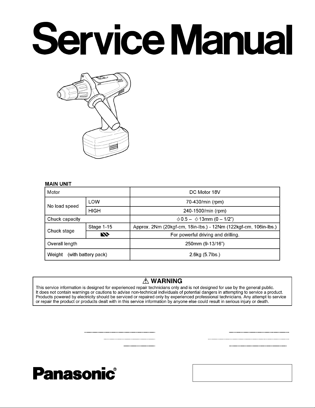
Cordless Drill & Driver
EY6450-U1
ORDER NO.PTD0308U33C1
F16
SPECIFICATIONS
CONTENTS
Page Page
1 SCHEMATIC DIAGRAM 2
2 WIRING CONNECTION DIAGRAM
3 DISASSEMBLY/ASSEMBLY INSTRUCTIONS
4 TROUBLESHOOTING GUIDE 7
2
5 EXPLODED VIEW
3
6 REPLACEMENT PARTS LIST
10
9
© 2003 Matsushita Electric Works Ltd. All rights
reserved. Unauthorized copying and distribution is a
violation of law.
Page 2
EY6450-U1
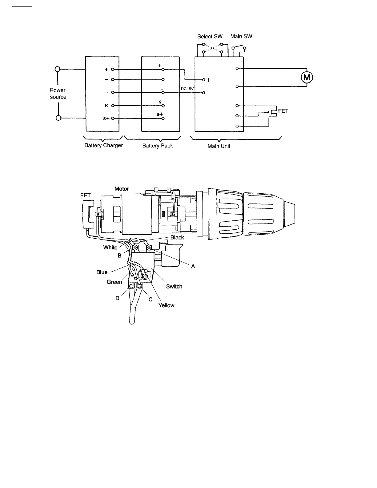
1 SCHEMATIC DIAGRAM
2 WIRING CONNECTION DIAGRAM
2
Page 3
3 DISASSEMBLY/ASSEMBLY INSTRUCTIONS
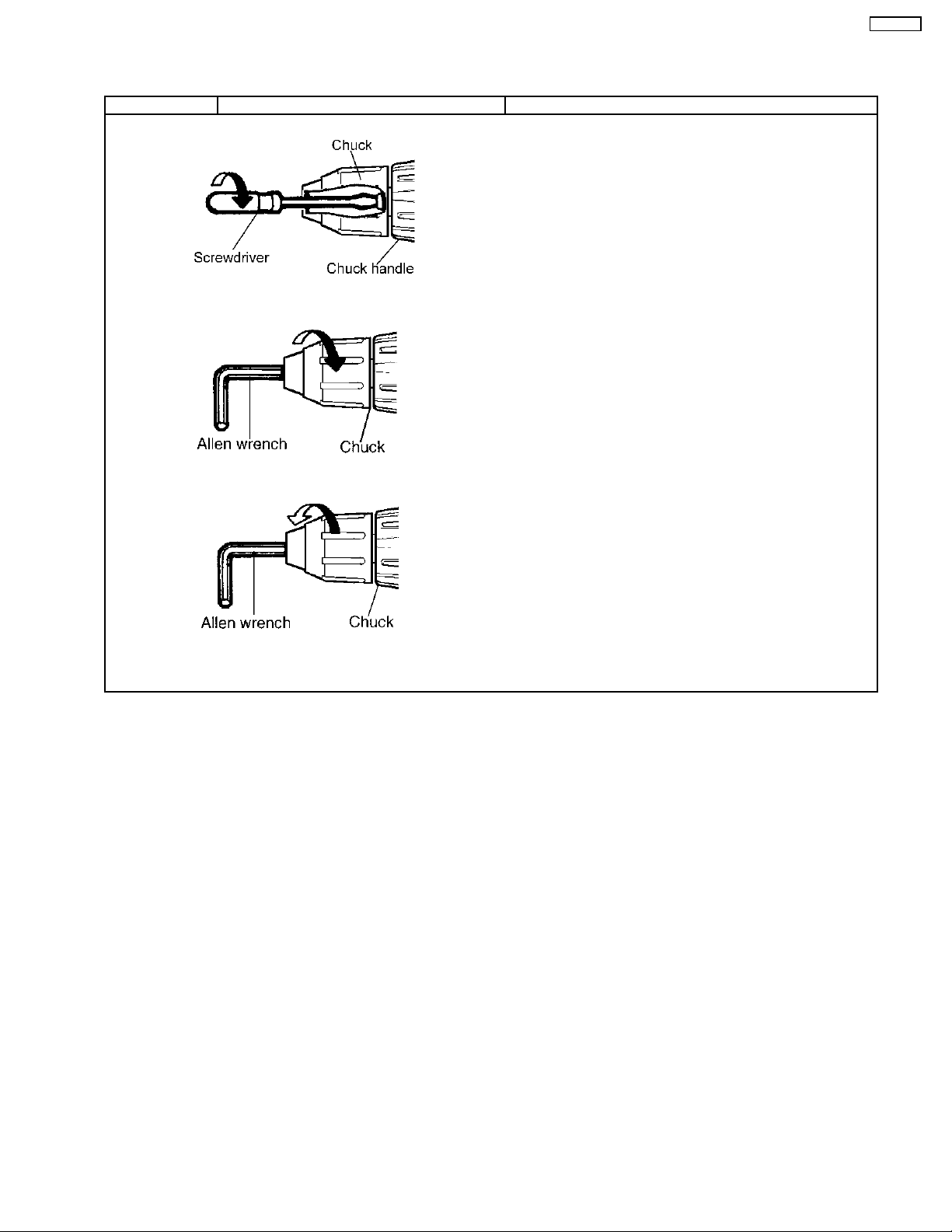
■HOW TO DISASSEMBLE KEYLESS CHUCK.
Ref. No. 1A Procedure 1A Removal of the Keyless Drill Chuck.
1. Set the clutch handle to position 1 and select "LOW" position.
2. Turn the lock collar counterclockwise direction to open the chuck
jaws.
3. Use a screwdriver to turn the chuck fastening screw inside the
chuck clockwise direction of the arrow, and remove the screw. (See
Fig. 1)
NOTE :
If the chuck fastening screw will not come loose, insert the
allen wrench into the chuck and lightly tap in the clockwise
direction with a ham mer to tighten the chuck, and then loosen
the chuck fastening screw. (See Fig. 2)
4. Insert the allen wrench into the chuck, and turn counterclockwise
Fig. 1
Fig. 2
direction in the arrow with holding the unit by the vise to remove
the chuck. (See Fig. 3)
EY6450-U1
Fig. 3
3
Page 4

EY6450-U1
■HOW TO DISASS EMBLE MAIN UNIT.
Ref. No. 2A Procedure 2A Removal of the Housing.
1. Remove the side handle. (See Fig. 4)
2. Remove nine housing screws. (See Fig. 5)
NOTE :
Grease rubbing part of housing with Shell Alvania for assembly.
(See Fig. 6)
Fig. 4
Fig. 6
Fig. 5
Ref. No. 2B Procedure 2A →→→→ 2B Removal or attachment of the Motor.
(Removal)
1. Take out the motor with the gear box block from housing.
2. Separate the motor from the gear box block by twisting the motor
to unlock tabs. (See Fig. 7)
(Attachment)
3. Motor mounting base and the positioning rib of gear case should
be set.
Fig. 7
4
Page 5

Ref. No. 2C Procedure 2A →→→→ 2B →→→→ 2C Removal or attachment of the Gear Box Block.
(Removal)
1. Turn the thrust plate to remove.
2. The internal parts of gear box block can be removed one after
another. (See Fig. 8)
(Attachment)
1. If the lock ring comes out, reassemble in the correct direction.
(See Fig. 9)
2. Start from inserting 6 pins into the driving block as shown in the
Fig. 10.
3. Assemble the other parts in reverse order as shown in the Fig.
8.
4. Install steel balls, pins and clutch springs into 6 holes. (See Fig.
11)
NOTE :
Carrier, Ring gear, and Clutch plate have their own correct
directions for proper assembly.
Fig. 8
EY6450-U1
Fig. 9
Fig. 10
Fig. 11
5
Page 6

EY6450-U1
Ref.No.2D Procedure 2A →→→→ 2B →→→→ 2C →→→→ 2D Assembly of the Adjusting Screw and the Clutch Handle.
1. Hold the driving block with the click spring on top, and align the
smallest projection of adjusting screw with the driving block at 5
o´clock position.
NOTE:
Make sure that the adjusting screw has its own correct direction
for proper assembly. Failure to do so, the clutch handle does
not rotate properly. (See Fig. 12)
2. Turn the adjusting screw into the driving block about 255°rotation
(to 2 o´clock position) for clockwise direction. (See Fig. 13)
3. Set the clutch handle with position 1 on top. (See Fig. 14)
Fig. 12
Fig. 14
Fig. 13
Ref.No.2E Procedure 2A →→→→ 2B →→→→ 2C →→→→ 2D →→→→ 2E Assembly of the Switch.
1. Press fit the lead wires firmly and set the black lead wire on top.
2. Connect the switch with the white and black lead wire at
55°position. (See Fig. 15).
Fig. 15
6
Page 7

4 TROUBLESHOOTING GUIDE
(Refer to WIRING CONNECTION DIAGRAM)
< TROUBLE > < CHECK > < REMEDY >
Does not operate. <CHECK BATTERY PACK.> NO Replace battery pack.
→
If no less than 18V DC is available across the (+) and (-) terminals,
the battery pack is OK.
NOTE:
<CHECK TERMINAL CONNECTIONS BETWEEN MAIN UNIT NO Repair contacts.
Check for proper terminal contacts.
Check continuity between following terminals. Replace switch & FET
* Inspection of the forward / reverse selection switch. block.
* Inspection of the brake.
The battery pack is sold separately as an optional accessory.
See the nearest sales dealer for details. The battery pack has a
limited life.
The pack should be replaced if;
- after being charged for the rated charging time the battery voltage
is less than 18V DC or the usable time is extremely short.
- the battery leaks. Check battery for leaks and terminals for
corrosion.
↓OK
AND BATTERY PACK.>
↓OK
<CHECK SWITCH BLOCK.> NO Contacts in switch block
(See WIRING CONNECTION DIAGRA M.)
When switch handle is depressed all the way:
- There should be 0Ω between (A) - (D) , and between (B) - (C) ;
when switch lever is set to forward side.
- There should be 0Ω between (A) - (C) , and between (B) - (D) ;
when switch lever is set to reverse side.
When switch handle is not depressed:
- There should be 0Ω between (A) - (B) .
→
→
→
are defective.
EY6450-U1
↓OK
<CHECK MOTOR.> NO Replace motor.
The motor normally operates with its white (+) and black (-) lead wires
connected to 18V DC.
→
7
Page 8

EY6450-U1
< TROUBLE > < CHECK > < REMEDY >
Does not speed- <CHECK FET.> NO Repair the contact
control or does not Even if FET block is defective, it can not be replaced individually. or replace switch
brake.
→
Replace whole switch block.
Remove the FET circuit block and check the lead wire terminals.
These terminals are open normally when there is an open circuit (
between the green and yellow lead wires, and between the blue and
yellow lead wires.
Ω)
→
& FET block.
NOTE:
* FET is weak against static electricity.
** The resistance value may be some differenc es depends on the
measurement range.
↓OK
<CHECK SWITCH BLOCK.> NO Replace switch & FET
→
block.
8
Page 9

5 EXPLODED VIEW
EY6450-U1
9
Page 10

EY6450-U1
6 REPLACEMENT PARTS LIST
NOTE:
*B=only available as set
*C=available individually
Ref.No. Part No. Part Name & Description Remarks Per Unit
1 WEY6450K3078 HOUSING AB SET 1
2 EY6481L0177 CLICK SPRING 1
3 WEY6450L6808 CHUCK FASTENING SCREW 1
5 WEY6450Y3228 CLUTCH HANDLE 1
6 WEY6450L0638 ADJUSTING SCREW 1
7 WEY6450L0578 CLUTCH PLATE 1
8 WEY6450L0168 CLUTCH SPRING (6pcs/PK) 6
9 WEY6813L1927 STEEL BALL (6pcs/PK) 5 6
10 WEY6450L0388 PIN (6pcs/PK) 5.3*20.3 6
11 WEY6450L1078 DRIVING BLOCK 1
12 EY6283L0377 PIN (6pcs/PK) 3.175*7.2 6
13 EY6901L1107 CARRIER 1
14 WEY6450L1488 RING GEAR 1
15 WEY6450L1348 PLANET GEAR (3pcs/PK) 3
16 WEY6450L0858 THRUST PLATE 1
17 WEY6450L1768 GEAR CASE 1
18 EY6406K9038 TORX TAPPING SCREW *C K3-12 4
19 WEY6450L1128 CARRIER A 1
20 WEY6450L1358 PLANET GEAR A (3pcs/PK) 3
21 WEY6200B1468 RING GEAR B 1
22 WEY6450L1118 CARRIER 1
23 WEY6450L1478 RING GEAR 1
24 EY6200B1367 PLANET GEAR (3pcs/PK) 3
25 WEY6450L0868 THRUST PLATE 1
26 WEY6450L0178 CLICK SPRING A 1
27 EY6406Y3238 H/L CHANGE HANDLE 1
28 WEY6405Y3248 F/R SELECTOR HANDLE 1
29 EYT184L6077 SCREW *C K4-6 2
30 WEY6450L0028 MOTOR MOUNTING PLATE 1
31 WEY6450L1008 DC MOTOR 1
32 WEY6450S6028 SEMS SCREW *C K3-5 2
33 WEY6450Y2008 SWITCH 1
34 EY6406L2568 HEAT SINK with a screw 1
35 EY6230L0207 DUST PREVENTIVE PLATE 1
36 EY6230K9218 TORX TAPPING SCREW *C K3-20 9
37 WEY6450L1458 GEAR BOX BLOCK 1
38 WEY6450K4628 SIDE HANDLE 1
- WEY6450K8108 OPERATING INSTRUCTIONS 1
**Battery Pack, Keyless Chuck, and Tool Case are available as an optional accessory.
See the nearest sales dealer for details.
***For replacement parts of charger, see the charger service manual.
Charger complete set is available as an optional accessory. See the nearest sales dealer for details.
10
 Loading...