

Panasonic ey46a2 Operation Manual
Operating Instructions
Bedienungsanleitung
Instructions d’utilisation
Istruzioni per l’uso
Gebruiksaanwijzing
Manual de instrucciones
Brugsvejledning
Driftsföreskrifter
Bruksanvisning
Käyttöohjeet
Çalıştırma Talimatları
Cordless Angle Grinder
Kabelloser Winkelschleifer
Meule d’angle sans fil
Smerigliatrice angolare senza fili
Snoerloze haakse slijper
Amoladora angular inalámbrica
Akku-vinkelslibemaskine
Sladdlös vinkelslipmaskin
Batteridrevet vinkelsliper
Ladattava kulmahiomakone
Kablosuz Avuç Taşlama Makinesi
Model No: EY46A2
Before operating this unit, please read these instructions completely and save this manual for future use.
Vor Inbetriebnahme des Gerätes die Betriebsanleitung bitte gründlich durchlesen und diese Broschüre
zum späteren Nachschlagen sorgfältig aufbewahren.
Lire entièrement les instructions suivantes avant de faire fonctionner l’appareil et conserver ce mode
d’emploi à des fi ns de consultation ultérieure.
Prima di usare questa unità, leggere completamente queste istruzioni e conservare il manuale per usi futuri.
Lees deze gebruiksaanwijzing aandachtig door voor u het apparaat in gebruik neemt en bewaar de
gebruiksaanwijzing voor eventuele naslag.
Antes de usar este aparato por primera vez, lea todas las instrucciones de este manual y guarde el
manual para poderlo consultar en el futuro.
Gennemlæs denne betjeningsvejledning før brugen og gem den til fremtidig brug.
Läs igenom hela bruksanvisningen innan verktyget tas i bruk. Spara bruksanvisningen för senare användning.
Før enheten tas i bruk, vennligst les disse alle anvisningene og oppbevar deretter bruksanvisningen for senere bruk.
Lue ohjeet huolella ennen laitteen käyttöönottoa ja säilytä tämä käyttöohje tallessa tulevaa tarvetta varten.
Bu cihazı çalıştırmadan önce lütfen bu talimatları dikkatli bir şekilde okuyun ve bu kılavuzu gelecekte kullanmak üzere saklayın.
01EngEY46A2(EU).indd1 2014/07/0916:07:21
Index/Index/Index/Indice/Index/Indice/Indeks/Index/Indeks/Hakemisto
10.8 V ─ 28.8 V
(Q)
English: Page 5
Deutsch: Seite 21
Français: Page 36
Italiano: Pagina 52
Nederlands: Bladzijde 68
Español: Página 84
Dansk: Side 100
Svenska: Sid 114
Norsk: Side 128
Suomi: Sivu 142
Türkçe: Sayfa 156
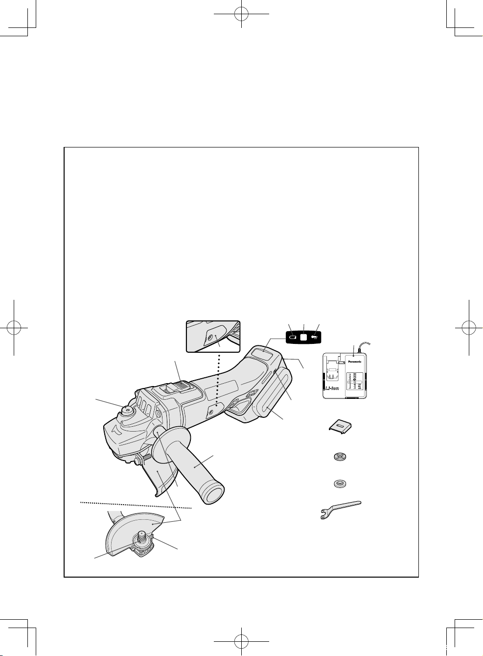
FUNCTIONAL DESCRIPTION
FUNKTIONSBESCHREIBUNG
DESCRIPTION DES FONCTIONS
DESCRIZIONE DELLE FUNZIONI
FUNCTIEBESCHRIJVING
DESCRIPCIÓN FUNCIONAL
FUNKTIONSBESKRIVELSE
FUNKTIONSBESKRIVNING
FUNKSJONSBESKRIVELSE
TOIMINTOKUVAUS
İŞLEVSEL AÇIKLAMA
(A)
(B)
(C)
(D)
(E) (F)
(P)
(G)
(O)
(H)
(I)
(Q)
(J)
(R)
(K)
(L)
(N)
01EngEY46A2(EU).indd2 2014/07/0916:07:23
(M)
-
2 -
(S)
(T)
Power switch
Netzschalter
Interrupteur d’alimentation
Interruttore di accensione
Hoofdschakelaar
Interruptor de alimentación
(A)
Afbryder
Strömbrytare
Strømbryter
Käyttökytkin
Açma/Kapama düğmesi
Display panel
Anzeigefeld
Ecran d’affi chage
Display
Displaypaneel
Panel de exhibición
(C)
Displaypanel
Display
Displaypanel
Näyttöpaneeli
Gösterge paneli
On lock warning lamp
Einschaltsicherungsleuchte
Témoin d’avertissement à verrou activé
Spia avvertenza blocco utensile
Waarschuwingslampje inschakelvergrendeling
Luz de advertencia de bloqueo
(E)
Låseadvarselslampe
Varningslampa för påslagningssäkring
Varsellampe for innkoblingssikring
Turvalukituksen merkkivalo
Kilit uyarı lambası
Battery pack release button
Akku-Entriegelungsknopf
Bouton de libération de batterie autonome
Tasto di rilascio pacco batteria
Accu-ontgrendeltoets
Botón de liberación de batería
(G)
Udløserknap til batteripakning
Frigöringsknapp för batteri
Utløserknapp for batteripakke
Akkupaketin irrotuspainike
Batarya paketi çıkarma düğmesi Akku-
Battery pack
Akku
Batterie autonome
Pacco batteria
Accu
Batería
(I)
Batteripakning
Batteri
Batteripakke
Akku
Batarya paketi
Brush cap
Bürstenkappe
Capuchon des charbons
Capsula spazzole
Borstelkap
Tapa de cepillo
(B)
Børstehætte
Borstlock
Børstehette
Harjan suojus
Fırça kapağı
Battery low warning lamp
Akkuladungs-Warnlampe
Témoin d’avertissement de batterie basse
Spia avvertenza batteria scarica
Waarschuwingslampje voor lage accuspanning
Luz de aviso de baja carga de batería
(D)
Advarselslampes batterieffekt lav
Varningslampa för svagt batteri
Varsellampe for at batteriet er for lavt
Alhaisen akkujännitteen varoituslamppu
Pil zayıf uyarı lambası
Overheat warning lamp (battery)
Überhitzungs-Warnlampe (Akku)
Témoin d’avertissement de surchauffe (batterie)
Spia avvertenza surriscaldamento (batteria)
Oververhitting-waarschuwingslampje (accu)
Luz de advertencia de sobrecalentamiento (batería)
(F)
Advarselslamp til overophedning (batteri)
Varningslampa för överhettning (batteri)
Varsellampe for overoppheting (batteri)
Ylikuumenemisen varoituslamppu (akku)
Aşırı ısınma uyarı lambası (batarya)
Alignment mark
Ausrichtmarkierung
Marque d’alignement
Marcatura di allineamento
Uitlijntekens
Marca de alineación
(H)
Flugtemærke
Anpassningsmärken
Innrettingsmerke
Sovitusmerkki
Hizalama işareti
Support handle
Zusatzgriff
Manche de support
Maniglia di sostegno
Handgreep
Mango de soporte
(J)
Hjælpehåndtag
Stödhandtag
Støttehåndtak
Tukikahva
Destek kolu
-
3 -
01EngEY46A2(EU).indd3 2014/07/0212:01:15

Support handle mounting hole
Montageloch für Stützgriff
Orifi ce de montage du manche de support
Foro montaggio maniglia di sostegno
Montage-opening van handgreep
Orifi cio de montaje de mango de soporte
(K)
Monteringshul til hjælpehåndtag
Monteringshål för stödhandtag
Monteringshull for støttehåndtak
Tukikahvan asennusaukko
Destek kolu montaj deliği
Grinding disc guard fi xing screw
Schleifscheibenschutzschraube
Vis de fi xation du carter de disque abrasif
Vite di fi ssaggio carter disco mola
Bevestigingsschroef van afbraamschijfbeschermkap
Tornillo de fi jación de protector de disco de amoladora
(M)
Slibeskivebeskytter skrue
Låsskruv för slipskivans skydd
Festeskrue for slipeskiveskjerm
Hiontalaikan suojuksen kiinnitysruuvi
Taşlama diski koruyucu sabitleme vidası
Spindle lock button
Spindelverriegelungstaste
Bouton de blocage de l’axe
Pulsante di blocco asse
Afbraamschijf
Botón de bloqueo de eje
(O)
Spindellåseknap
Spindelns låsknapp
Spindellåseknapp
Karan lukituspainike
İşmili kilitleme düğmesi
Battery pack cover
Akkuabdeckung
Couvercle de la batterie autonome
Coperchio batterie
Accudeksel
Cubierta de la batería
(Q)
Akkuafdækning
Batterilock
Batteripakkedeksel
Akun liitinsuoja
Batarya paketi kapağı
Disc fl ange
Scheibenfl ansch
Flasque du disque
Flangia disco
Schijffl ens
Brida de disco
(S)
Skivefl ange
Skivfl äns
Skivefl ens
Laikan lukituslaippa
Disk fl anşı
Grinding disc guard
Schleifscheibenschutz
Carter de disque abrasif
Carter disco mola
Afbraamschijfbeschermkap
Protección de disco de desbastado
(L)
Slibeskivebeskytter
Slipskivans skydd
Slipeskiveskjerm
Hiomalaikan suojus
Taşlama diski koruyucu
Spindle
Spindel
Axe
Asse
As
Eje
(N)
Spindel
Spindel
Spindel
Kara
İşmili
Battery charger
Ladegerät
Chargeur de batterie
Caricabatterie
Acculader
Cargador de batería
(P)
Batterioplader
Batteriladdare
Batterilader
Akkulaturi
Batarya şarj cihazı
Clamp nut
Mutter
Écrou de serrage de collier
Dado di fi ssaggio
Klemmoer
Tuerca de abrazadera
(R)
Møtrik
Mutter
Klemmutter
Aluslevy
Sıkma somunu
Disc wrench
Scheibenschlüssel
Clé de disque
Chiave per il disco
Schijfsleutel
Llave de disco
(T)
Skivenøgle
Skivnyckel
Skivenøkkel
Lukituslaipan avain
Disk anahtarı
-
4 -
01EngEY46A2(EU).indd4 2014/07/0212:01:16
Original instructions: English
Translation of the original instructions:
Other languages
WARNING
To reduce the risk of injury, always use
proper guards when grinding.
I. INTENDED USE
Thank you for purchasing the Panasonic
Angle Grinder. The powerful grinding
action of this tool, combined with the
convenience of its rechargeable battery
pack, provides you with great grinding
performance.
This Angle Grinder is only to be used for
grinding and cutting-off.
DANGER
This product is a grinding tool, designed
to grind. It has a rotating disc which is
capable of cutting you deeply, causing
serious injury or death. As a result,
please read this manual and the
cautionary markings on the tool carefully, and obey all of the Safety Instructions
to avoid such injury.
How to Use This Manual
• Please read this manual completely
before starting to use your grinder. If
you let someone else use the grinder,
make sure they either read this manual
or are fully instructed in the proper use
and all safety precautions concerning
the grinder.
• Please keep this manual for future
reference. It contains important
safety information that you must
follow to use the grinder safely.
• This manual and product use the
following signal words:
NOTE:
Notes provide additional information
that you should know about the grinder.
CAUTION
Caution indicates a potentially hazardous
situation, which could result in minor or
moderate injury if not avoided. Cautions
also alert you to unsafe practices to be
avoided.
WARNING
Warning indicates a potentially
hazardous situation, which could result
in serious injury or death if not avoided.
DANGER
Danger indicates an imminent hazard
which will result in serious injury or
death if not avoided.
-
5 -
01EngEY46A2(EU).indd5 2014/07/0212:01:16

Read the “Safety Instructions”
booklet and the following before using.
II. ADDITIONAL
SAFETY RULES
Safety instructions for all
operations
Safety warning common for Grinding
or Abrasive Cutting-off operations:
1) This power tool is intended to
function as a grinder, or cut-off
tool. Read all safety warnings,
instructions, illustrations and
specifications provided with this
power tool. Failure to follow all
instructions listed below may result in
electric shock, fire and/or serious
injury.
2)
Operations such as sanding, wire
brushing, polishing are not
recommended to be performed with
this power tool. Operations for which
the power tool was not designed may
create a hazard and cause personal
injury.
3) Do not use accessories which
are not specifically designed
and recommended by the tool
manufacturer. Just because the
accessory can be attached to your
power tool, it does not assure safe
operation.
4) The rated speed of the accessory
must be at least equal to the
maximum speed marked on the
power tool. Accessories running
faster than their RATED SPEED can
break and fly apart.
5) The outside diameter and the
thickness of your accessory must
be within the capacity rating of
your power tool. Incorrectly sized
accessories cannot be adequately
guarded or controlled.
6) Threaded mounting of accessories
must match the grinder spindle
thread. For accessories mounted
by flanges, the arbour hole of the
accessory must fit the locating
diameter of the flange. Accessories
that do not match the mounting
hardware of the power tool will run
out of balance, vibrate excessively
and may cause loss of control.
7) Do not use a damaged accessory.
Before each use inspect the
accessory such as abrasive
wheels for chips and cracks.
If power tool or accessory is
dropped, inspect for damage or
install an undamaged accessory.
After inspecting and installing an
accessory, position yourself and
bystanders away from the plane of
the rotating accessory and run the
power tool at maximum no-load
speed for one minute. Damaged
accessories will normally break apart
during this test time.
8) Wear personal protective
equipment. Depending on
application, use face shield,
safety goggles or safety glasses.
As appropriate, wear dust mask,
hearing protectors, gloves
and workshop apron capable
of stopping small abrasive or
workpiece fragments. The eye
protection must be capable of
stopping flying debris generated
by various operations. The dust
mask or respirator must be capable
of filtrating particles generated by
your operation. Prolonged exposure
to high intensity noise may cause
hearing loss.
9) Keep bystanders a safe distance
away from work area. Anyone
entering the work area must wear
personal protective equipment.
Fragments of workpiece or of a
broken accessory may fly away and
cause injury beyond immediate area
of operation.
10) Hold the power tool by insulated
gripping surfaces only, when
performing an operation where the
cutting tool may contact hidden
wiring. Contact with a “live” wire
will also make exposed metal
parts of the power tool “live” and
could give the operator an electric
shock.
-
6 -
01EngEY46A2(EU).indd6 2014/07/0212:01:16

11) Position the cord clear of the
spinning accessory. If you lose
control, the cord may be cut or
snagged and your hand or arm may
be pulled into the spinning accessory.
12) Never lay the power tool down
until the accessory has come
to a complete stop. The spinning
accessory may grab the surface and
pull the power tool out of your control.
13) Do not run the power tool while
carrying it at your side. Accidental
contact with the spinning accessory
could snag your clothing, pulling the
accessory into your body.
14) Regularly clean the power tool’s
air vents. The motor’s fan will draw
the dust inside the housing and
excessive accumulation of powdered
metal may cause electrical hazards.
15) Do not operate the power tool near
flammable materials. Sparks could
ignite these materials.
16) Do not use accessories that
require liquid coolants. Using water
or other liquid coolants may result in
electrocution or shock.
Further safety instructions for
all operations
Kickback and Related Warnings
Kickback is a sudden reaction to a
pinched or snagged rotating wheel,
backing pad, brush or any other
accessory. Pinching or snagging
causes rapid stalling of the rotating
accessory which in turn causes
the uncontrolled power tool to be
forced in the direction opposite of the
accessory’s rotation at the point of the
binding.
For example, if an abrasive wheel is
snagged or pinched by the workpiece,
the edge of the wheel that is entering
into the pinch point can dig into the
surface of the material causing the
wheel to climb out or kick out. The
wheel may either jump toward or
away from the operator, depending on
direction of the wheel’s movement at
the point of pinching. Abrasive wheels
may also break under these conditions.
Kickback is the result of power tool
misuse and/or incorrect operating
procedures or conditions and can be
avoided by taking proper precautions
as given below.
1) Maintain a firm grip on the power
tool and position your body
and arm to allow you to resist
kickback forces. Always use
auxiliary handle, if provided, for
maximum control over kickback
or torque reaction during start-up.
The operator can control torque
reactions or kickback forces, if proper
precautions are taken.
2) Never place your hand near the
rotating accessory. Accessory may
kickback over your hand.
3) Do not position your body in the
area where power tool will move
if kickback occurs. Kickback will
propel the tool in direction opposite to
the wheel’s movement at the point of
snagging.
4) Use special care when working
corners, sharp edges etc. Avoid
bouncing and snagging the
accessory. Corners, sharp edges or
-
7 -
01EngEY46A2(EU).indd7 2014/07/0212:01:16

bouncing have a tendency to snag
the rotating accessory and cause
loss of control or kickback.
5) Do not attach a saw chain
woodcarving blade or toothed saw
blade. Such blades create frequent
kickback and loss of control.
wheels may be different from grinding
wheel flanges.
6) Do not use worn down wheels
from larger power tools. Wheel
intended for larger power tool is not
suitable for the higher speed of a
smaller tool and may burst.
Additional safety instructions
for grinding and cutting-off
operations
Safety warnings specific for Grinding
and Abrasive Cutting-off operations:
1) Use only wheel types that are
recommended for your power tool
and the specific guard designed
for the selected wheel. Wheels
for which the power tool was not
designed cannot be adequately
guarded and are unsafe.
2) The grinding surface of centre
depressed wheels must be
mounted below the plane of the
guard lip. An improperly mounted
wheel that projects through the plane
of the guard lip cannot be adequately
protected.
3) The guard must be securely
attached to the power tool and
positioned for maximum safety,
so the least amount of wheel is
exposed towards the operator.
The guard helps to protect operator
from broken wheel fragments and
accidental contact with wheel and
sparks that could ignite clothing.
4) Wheels must be used only for
recommended applications. For
example: do not grind with the
side of cut-off wheel. Abrasive
cut-off wheels are intended for
peripheral grinding, side forces
applied to these wheels may cause
them to shatter.
5) Always use undamaged wheel
flanges that are of correct size and
shape for your selected wheel.
Proper wheel flanges support the
wheel thus reducing the possibility of
wheel breakage. Flanges for cut-off
Additional Safety Warnings
Specific for Abrasive CuttingOff Operations:
1) Do not “jam” the cut-off wheel
or apply excessive pressure. Do
not attempt to make an excessive
depth of cut. Overstressing the
wheel increases the loading and
susceptibility to twisting or binding
of the wheel in the cut and the
possibility of kickback or wheel
breakage.
2) Do not position your body in
line with and behind the rotating
wheel. When the wheel, at the point
of operation, is moving away from
your body, the possible kickback may
propel the spinning wheel and the
power tool directly at you.
3) When wheel is binding or when
interrupting a cut for any reason,
switch off the power tool and hold
the power tool motionless until
the wheel comes to a complete
stop. Never attempt to remove the
cut-off wheel from the cut while
the wheel is in motion otherwise
kickback may occur. Investigate
and take corrective action to
eliminate the cause of wheel binding.
4) Do not restart the cutting
operation in the workpiece. Let
the wheel reach full speed and
carefully reenter the cut. The
wheel may bind, walk up or kickback
if the power tool is restarted in the
workpiece.
5) Support panels or any oversized
workpiece to minimize the risk
of wheel pinching and kickback.
Large workpieces tend to sag under
their own weight. Supports must be
placed under the workpiece near
-
8 -
01EngEY46A2(EU).indd8 2014/07/0212:01:16
the line of cut and near the edge of
the workpiece on both sides of the
wheel.
6) Use extra caution when making a
“pocket cut” into existing walls or
other blind areas. The protruding
wheel may cut gas or water pipes,
electrical wiring or objects that can
cause kickback.
Symbol Meaning
V Volts
Direct current
n Rated speed
Revolutions or reciproca-
-1
… min
Ah
tions per minutes
Electrical capacity of
battery pack
To reduce the risk of
injury, user must read and
understand instruction
manual.
For indoor use only.
Otherwise, the battery may overheat,
catch fire, or explode.
• Never use other than the dedicated
charger to charge the battery pack.
Otherwise, the battery may leak,
overheat, or explode.
• After removing the battery pack
from the tool or the charger, always
reattach the pack cover. Otherwise,
the battery contacts could be
shorted, leading to a risk of fire.
• When the Battery Pack Has
Deteriorated, Replace It with a New
One. Continued use of a damaged
battery pack may result in heat
generation, ignition or battery
rupture.
III. ASSEMBLY
NOTE:
When attaching or removing a support
handle, disconnect battery pack from
tool.
Always wear eye protec-
tion
WARNING
• Do not use other than the Panasonic
battery packs that are designed for
use with this rechargeable tool.
• Panasonic is not responsible for any
damage or accident caused by the
use of the recycled battery pack and
the counterfeit battery pack.
• Do not dispose of the battery pack in
a fire, or expose it to excessive heat.
• Do not drive the likes of nails
into the battery pack, subject it to
shocks, dismantle it, or attempt to
modify it.
• Do not allow metal objects to touch
the battery pack terminals.
• Do not carry or store the battery
pack in the same container as nails
or similar metal objects.
• Do not charge the battery pack in a
high-temperature location, such as
next to a fire or in direct sunlight.
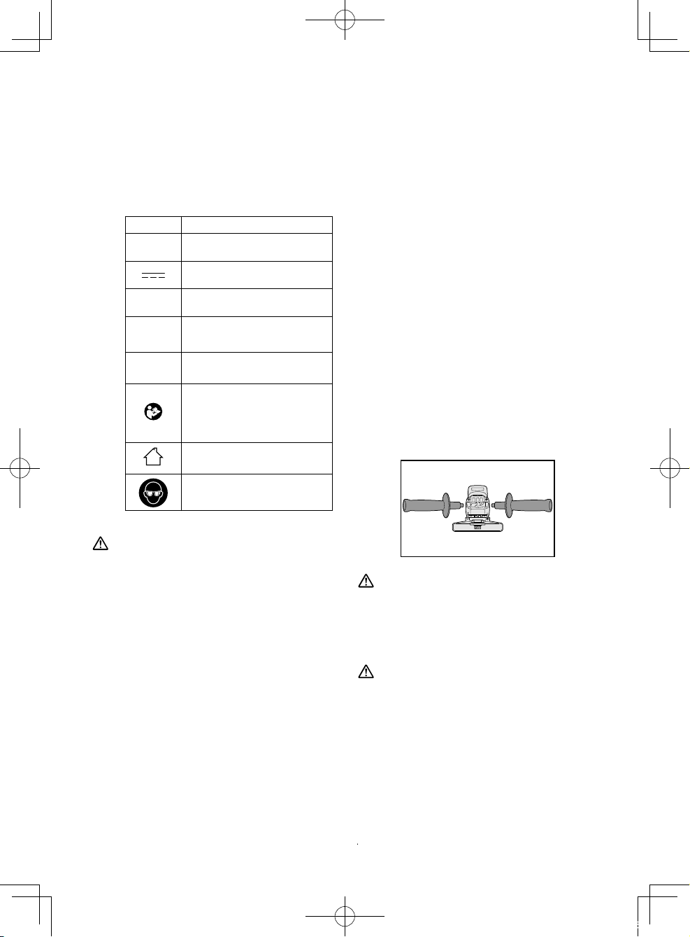
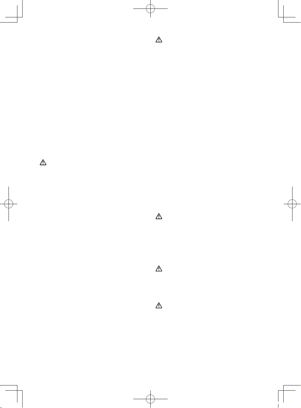
CAUTION
Always be sure that the support handle is
installed securely before operation.
• Screw the side handle securely as
shown in the figure.
CAUTION:
Never actuate the lock pin when the
spindle is rotating. The tool may be damaged.
• Press the lock button to prevent spindle
rotation when installing or removing
parts, such as grinding disc, disc guard,
etc.
-
9 -
01EngEY46A2(EU).indd9 2014/07/0212:01:16
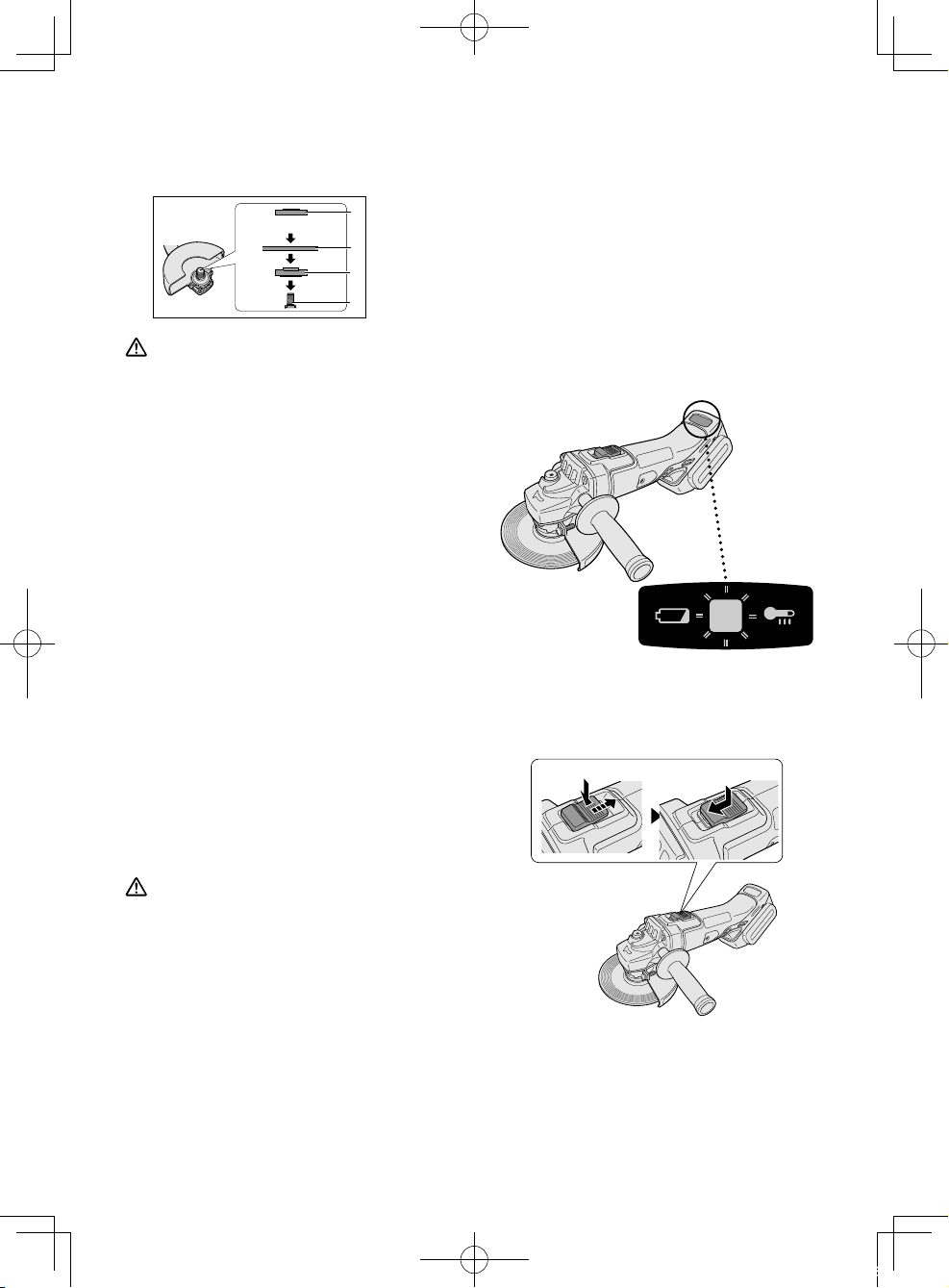
Installing or removing disc
Inspection before use
• Has the correct grinding disc been
mounted for the object to be ground?
• Has the proper diameter of the
grinding disc been mounted for the
tool rating?
• Has the correct disc been fitted in
compliance safety standards listed
below?
Europe - EN,Australia - AS
1. Grinding disc
1
guard
2. Spindle
2
Grinding disc
3.
guard fixing
screw
3
CAUTION
• When using, the Grinding disc guard
must be installed on the tool so that
the closed side of the guard always
faces toward the operator.
• Ensure that blotters are used when
they are provided with the bonded
abrasive product and when they are
required;
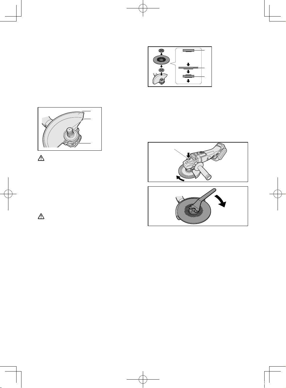
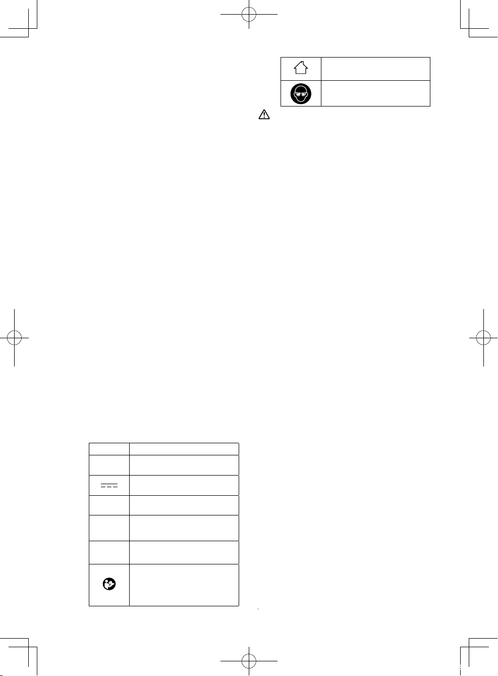
1. Install the Grinding disc guard, and then
securely tighten the screw.
1. Clamp nut
1
Make sure
the side.
2. Grinding disc
3. Disc flange
2
3
2. Install the disc flange and the disc to the
spindle in order as shown in the figure.
3.
Tighten the clamp nut onto the spindle so
that hollow side faces opposite direction
to the disc.
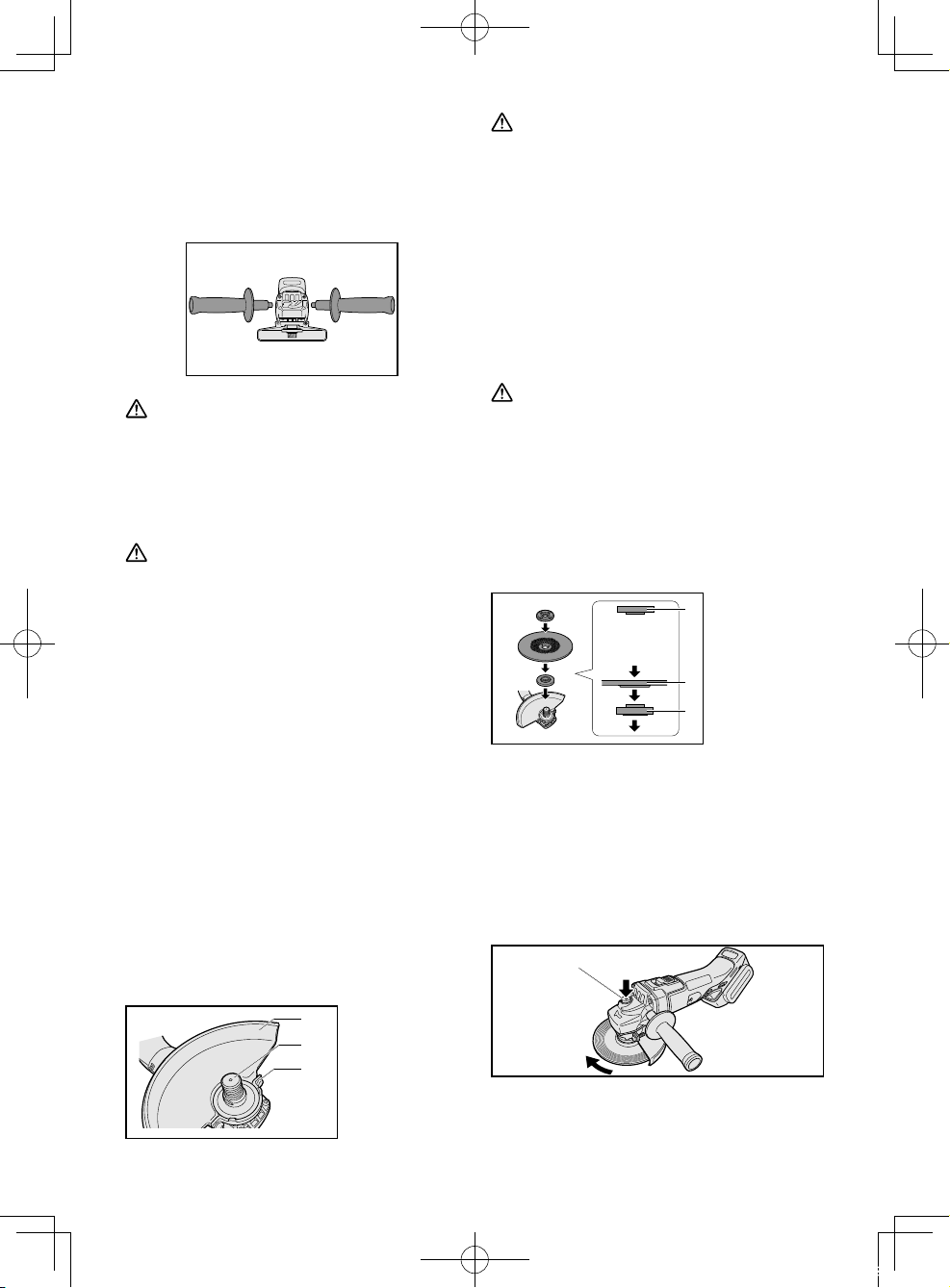
4. Push the Spindle lock button to secure
the spindle in place, and then use the
clamp nut wrench to tighten the clamp
nut securely.
Spindle lock button
WARNING:
Always use supplied guard when using
tool. Grinding disc can shatter during
use and Grinding disc guard helps to
reduce chances of personal injury.
01EngEY46A2(EU).indd10 2014/07/0212:01:19
5. To remove the grinding disc, follow the
installation procedure in reverse.
-
10 -
Attaching or Removing
Battery Pack
CAUTION
Before inserting battery pack, check that
the power switch on the tool actuates
properly and returns to the “OFF”
position when released.
IV. OPERATION
NOTE:
Be aware that this tool is always in an
operating condition, since it does not have
to be plugged into an electrical outlet.
Power switch operation
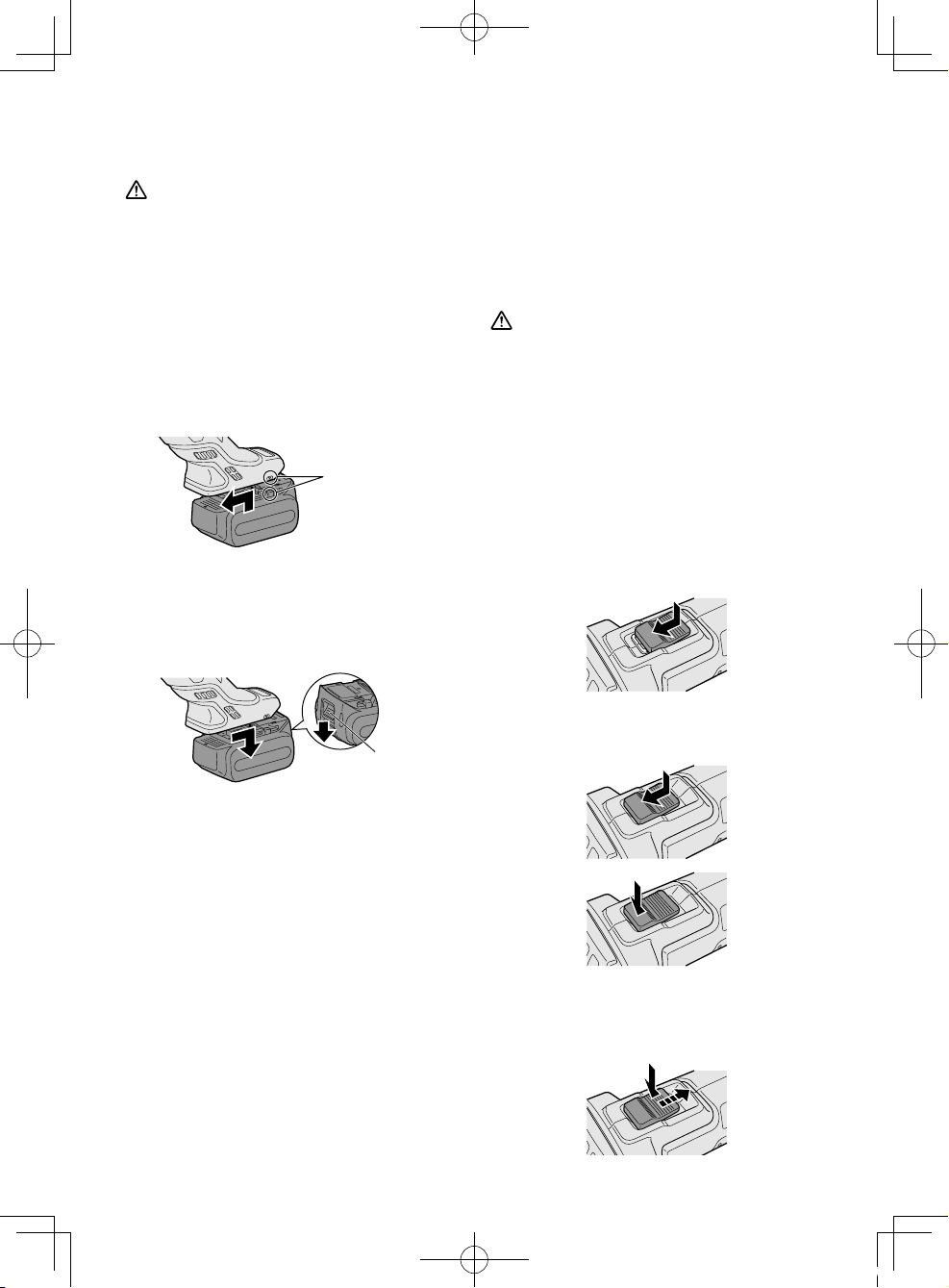
1. To connect the battery pack:
Align the highlighted marker points
and attach battery pack.
• Slide the battery pack until it locks
into position.
Alignment
marks
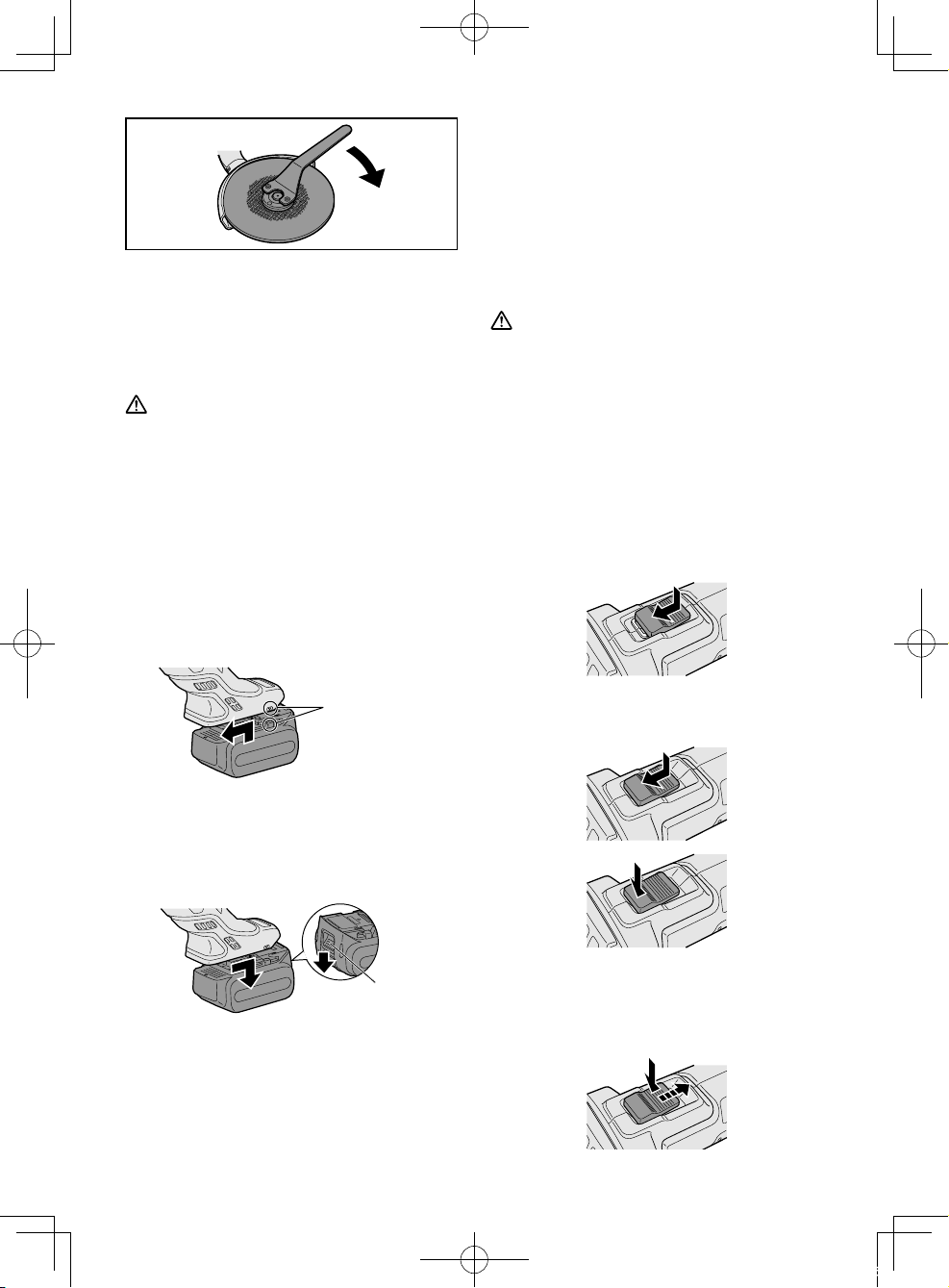
2. To remove the battery pack:
Push down the button and slide the
battery pack forward.
Button
CAUTION
• Before inserting the battery pack
into the tool, always make sure that
the power switch operates properly
and returns to the “OFF” position
when the rear of the power switch is
depressed.
• Power switch can be locked in “ON”
position. Stay alert when locking tool
in “ON” position and grasp the tool
firmly using support handle and grip.
To start operation, press and slide the
power switch toward the “ON” position.
For continuous operation, press the
front of the power switch to lock it.
To stop the tool, press the rear of the
power switch, then it returns to the
“OFF” position.
-
11 -
01EngEY46A2(EU).indd11 2014/07/0212:01:21
WARNING
• It should never be necessary to
force the tool. The weight of the tool
applies adequate pressure. Forcing
and excessive pressure could cause
dangerous grinding disc breakage.
• ALWAYS replace grinding disc if tool
is dropped while grinding.
• NEVER bang or hit grinding disc.
• Avoid bouncing and snagging the
grinding disc, especially when
working corners, sharp edges etc.
This can cause loss of control and
kickback.
CAUTION
After operation, always switch off the
tool and wait until the wheel has come to
a complete stop before putting the tool
down.
Visual inspection and workout
test on disc
1. Always make sure that the disc has no
cracks before use.
2. Always give workout test on the blade
as follows.
3. Always make sure the disc is firmly
fixed.
Work out time
Brand new disc more than 3 min.
Before use on
current disc
more than 1 min.
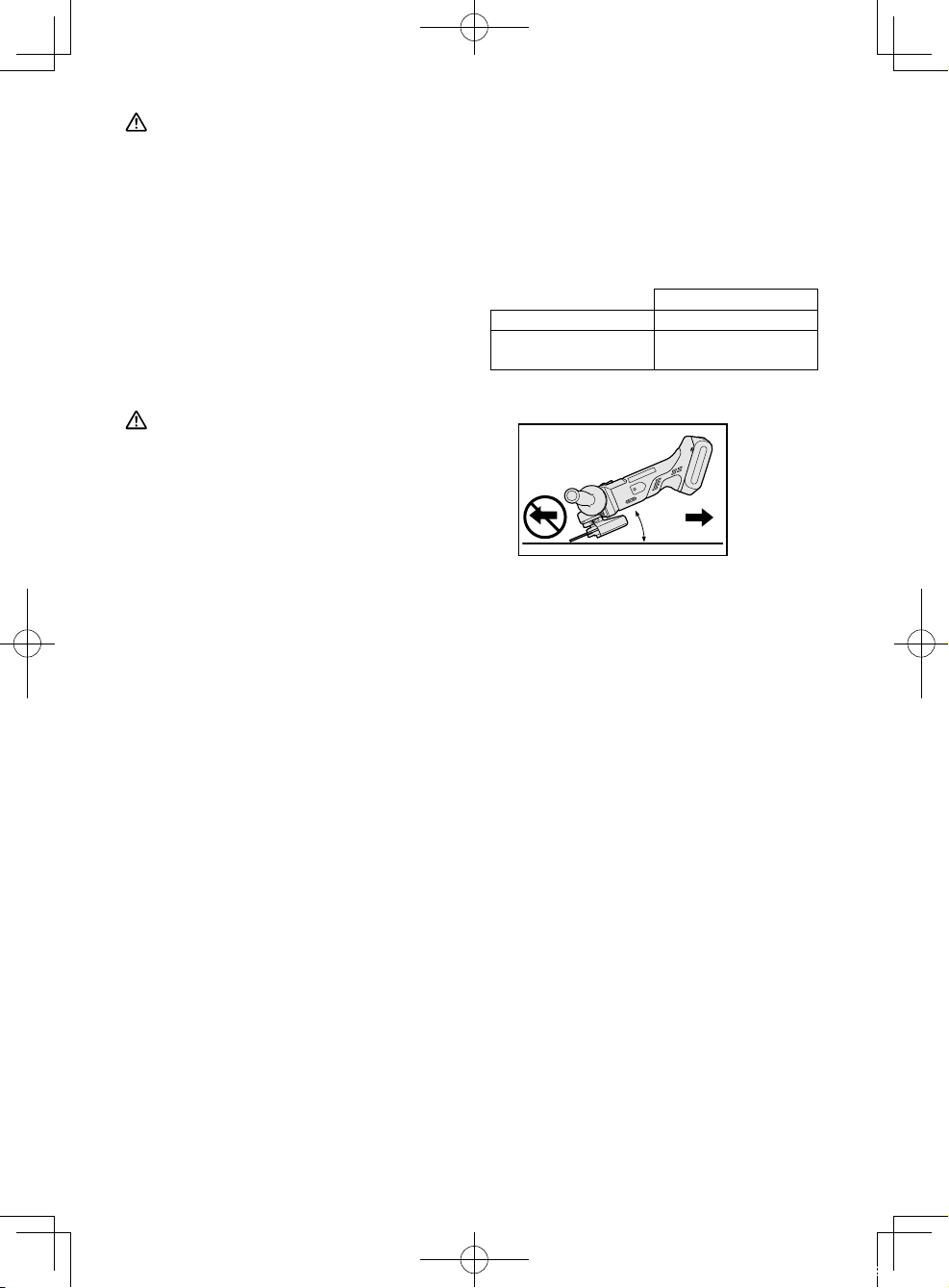
Grinding operation
°
B
ALWAYS hold the tool firmly with one
hand on grip and the other on the
support handle. Turn on the tool and
then apply the wheel or disc to the
workpiece.
In general, keep the edge of the wheel
or grinding disc at an angle of about
15º-30º to the workpiece surface.
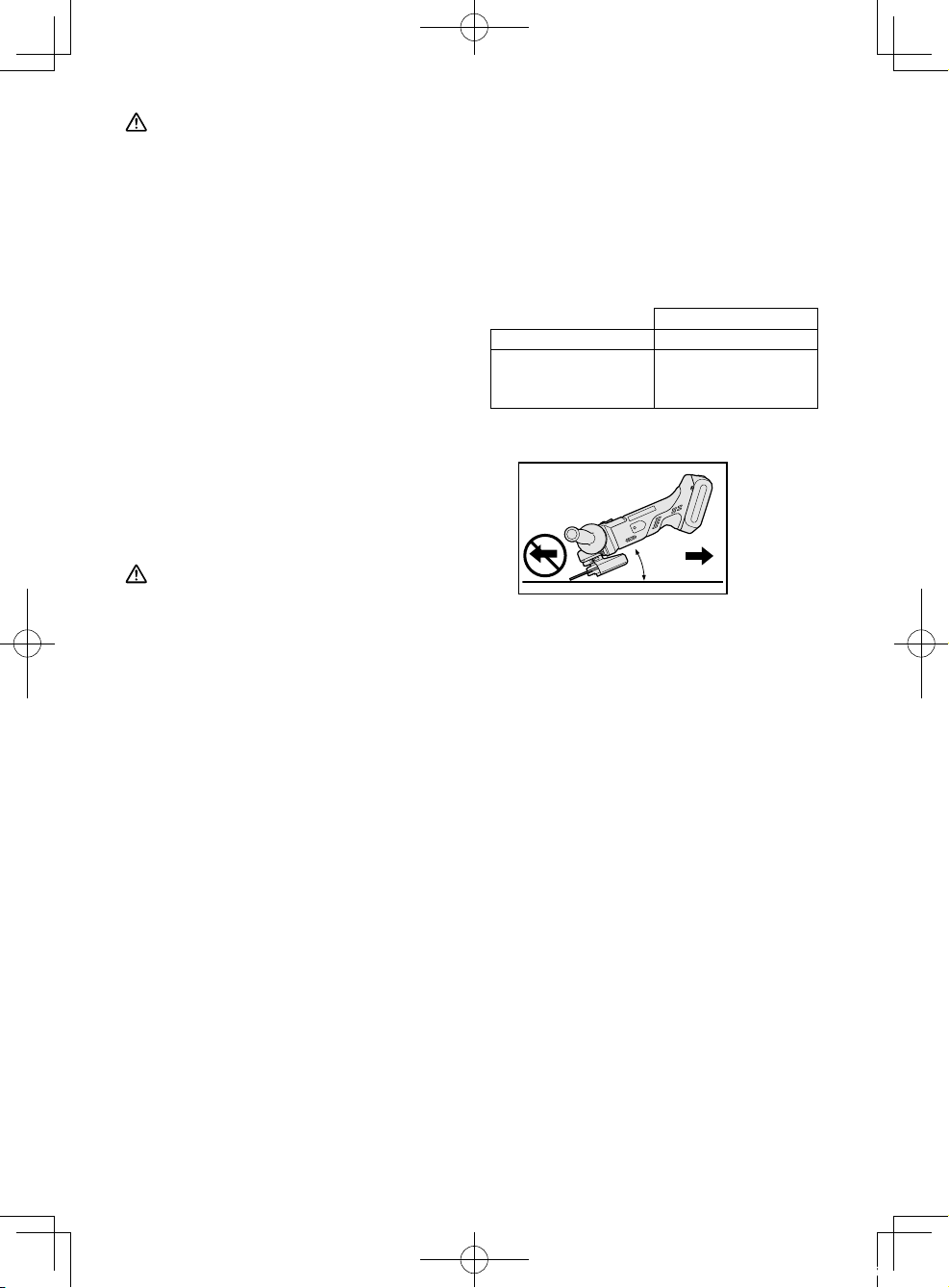
When using a new grinding disc, do
not work the grinder in the B direction
or it will cut into the workpiece. Once
the edge of the grinding disc has
been rounded off by use, the grinding
disc may be worked in both A and B
direction.
15°~30
A
-
12 -
01EngEY46A2(EU).indd12 2014/07/0212:01:22
Using a cut-off disc guard
(Available as an accessory, not
included)
1. Clamp nut
1
Make sure the side.
WARNING
• When using an abrasive cut-off disc,
be sure to use only the cut-off disc
guard designed for this use with
cut-off disc.
• NEVER use cut-off disc for grinding.
• Do not jam the Disc or apply
excessive pressure. Do not attempt
to make an excessive depth of
cut. Overstressing the cut-off
disc increases the loading and
susceptibility to twisting or binding
of the cut-off disc in the cut and the
possibility of kickback, cut-off disc
breakage and overheating of the
motor may occur.
• Do not start when disc is in the
workpiece. To do so causes the
cut-off disc binding or kickback. Let
the cut-off disc reach full speed and
then carefully cut the workpiece.
• During cutting operations, never
change the angle of the disc. Placing
side pressure on the cut-off disc
(as in grinding) will cause the disc
to crack and break, causing serious
personal injury.
2. Cut-off disc
3. Disc flange
4. Spindle
2
3
4
• Use the tool in such a way as to
prevent the air from the ventilation
slots from blowing directly onto your
skin. Otherwise, you may get burned.
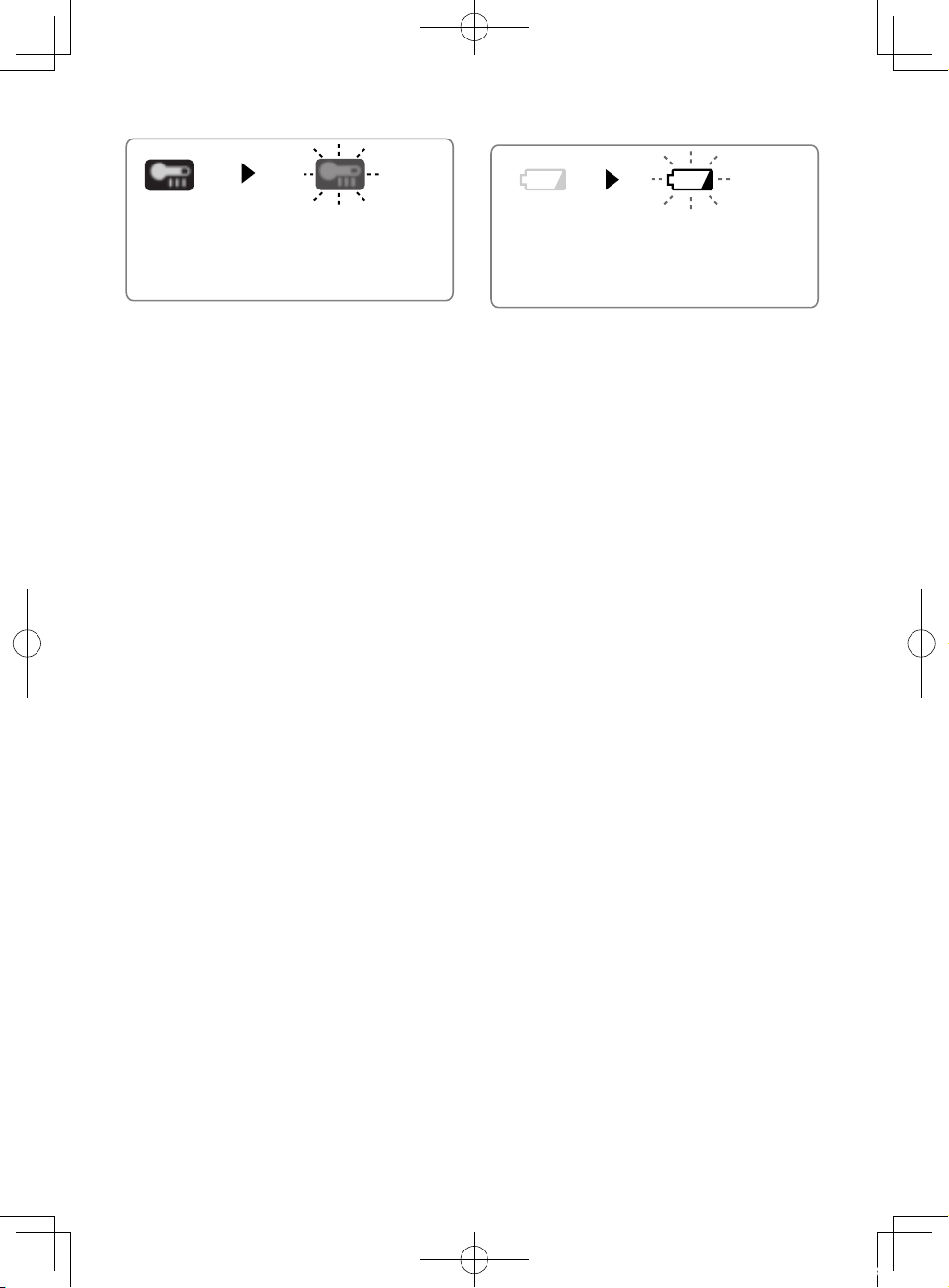
Indicator lamp for On lock
start prevention function
The grinder will not start when the
battery pack is inserted with the switch
at the ON position (switch lever at ON).
The warning lamp will flash at this
time to indicate that the ‘On lock start
prevention function’ has operated.
Press the switch to the OFF position
(switch lever at OFF) and then press it
back to the ON position (switch lever at
ON) to start the grinder.
ON→OFF OFF→ON
CAUTION
• To prevent excessive temperature
increase of the tool surface, do not
operate the tool continuously using
two or more battery packs. The tool
needs cool-off time before switching
to another pack.
• Do not close up ventilation slots
on the sides of the body during
operation. Otherwise, the machine
function is adversely affected to
cause a failure.
• Do not strain the tool (motor). This
may cause damage to the unit.
-
13 -
01EngEY46A2(EU).indd13 2014/07/0212:01:23
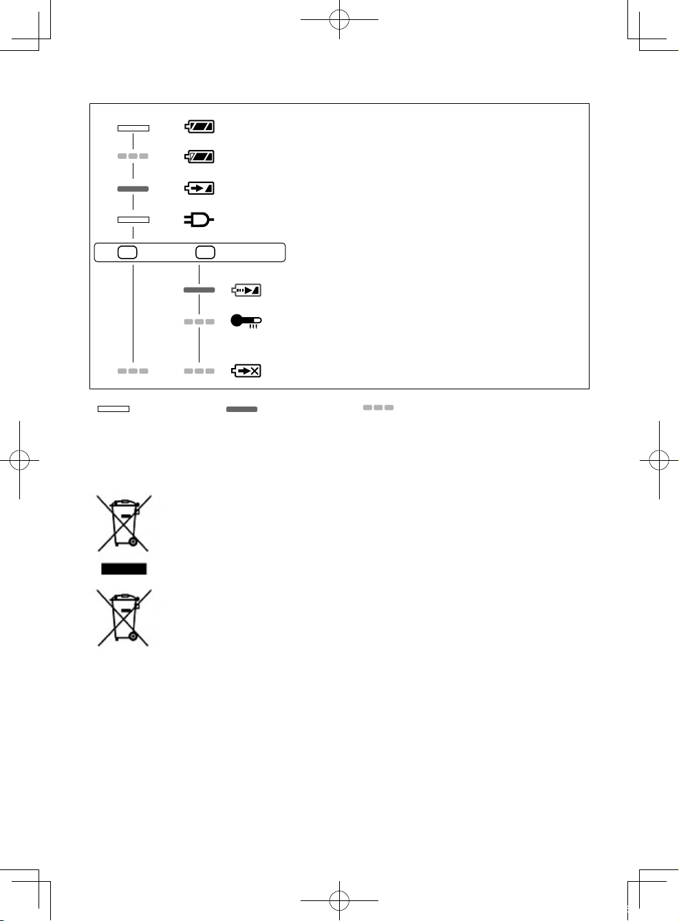
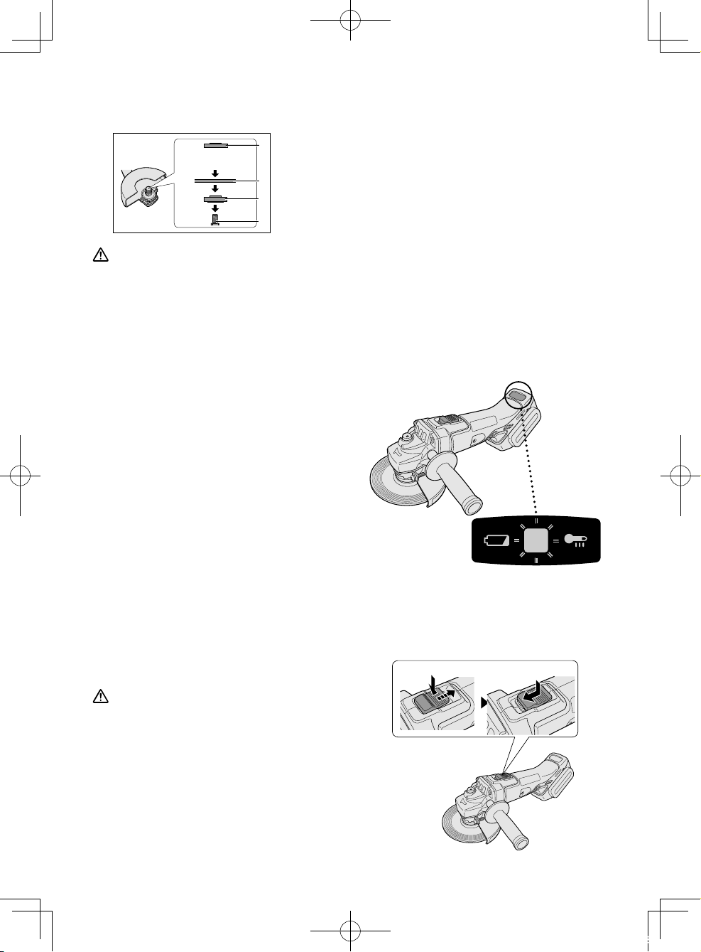
Overheat warning lamp
g
Battery low warning lamp
Off
(normal
operation)
Flashing: Overheat
Indicates operation has
been halted due to battery
overheatin
.
To protect the battery, be sure to note
the following when carrying out this
operation.
• If the battery becomes hot, the
protection function will be activated
and the motor or battery will stop
operating. The overheat warning lamp
on the control panel illuminates or
flashes when this feature is active.
• If the overheating protection feature
activates, allow the tool to cool
thoroughly (at least 30 minutes).
The tool is ready for use when the
overheat warning lamp goes out.
• Avoid using the tool in a way that
causes the overheating protection
feature to activate repeatedly.
• If the tool is operated continuously
under high-load conditions or if it is
used in hot-temperature conditions
(such as during summer), the
overheating protection feature may
activate frequently.
• If the tool is used in cold-temperature
conditions (such as during winter) or
if it is frequently stopped during use,
the overheating protection feature
may not activate.
• The performance of the EY9L42
deteriorates significantly at and below
10°C due to work conditions and
other factors.
• The ambient temperature range
is between 0°C (32°F) and 40°C
(104°F). If the battery pack is used
when the battery temperature is
below 0°C (32°F), the tool may fail to
function properly.
• When charging a cool battery pack
(below 0°C (32°F)) in a warm place,
leave the battery pack at the place
and wait for more than one hour to
warm up the battery to the level of the
ambient temperature.
Off
(normal
operation)
Flashing
(No charge)
Battery protection feature
active
Excessive (complete) discharging of
lithium ion batteries shortens their
service life dramatically. The tool
includes a battery protection feature
designed to prevent excessive
discharging of the battery pack.
• The battery protection feature activates
immediately before the battery loses
its charge, causing the battery low
warning lamp to flash.
• If you notice the battery low warning
lamp flashing, charge the battery pack
immediately.
• If it is started with too little battery
power remaining, the tool may stop
operating without the battery low
warning lamp flashing first. This
indicates that there is too little battery
power remaining to use the tool, and
the battery pack should be charged
before further use.
• If the tool is subject to a sudden load
during use that causes the motor to
lock up, the overdischarge prevention
sensor may be triggered, and the
battery low warning lamp may flash.
The lamp will stop flashing once you
address the cause of the motor’s
locking up and cycle the trigger.
-
14 -
01EngEY46A2(EU).indd14 2014/07/0212:01:24
[Battery Pack]
For Appropriate Use of
Battery pack
Li-ion Battery pack
• For optimum battery life, store the
Li-ion battery pack following use
without charging it.
• When charging the battery pack,
confirm that the terminals on the
battery charger are free of foreign
substances such as dust and
water etc. Clean the terminals before
charging the battery pack if any
foreign substances are found on the
terminals.
The life of the battery pack terminals
may be affected by foreign substances such as dust and water etc.
during operation.
• When battery pack is not in use, keep
it away from other metal objects like:
paper clips, coins, keys, nails, screws,
or other small metal objects that can
make a connection from one terminal
to another.
Shorting the battery terminals together
may cause sparks, burns or a fire.
• When operating the battery pack,
make sure the work place is well
ventilated.
• When the battery pack is removed
from the main body of the tool, replace
the battery pack cover immediately
in order to prevent dust or dirt from
contaminating the battery terminals
and causing a short circuit.
Battery Pack Life
The rechargeable batteries have
a limited life. If the operation time
becomes extremely short after
recharging, replace the battery pack
with a new one.
Battery Recycling
ATTENTION:
For environmental protection and
recycling of materials, be sure that it
is disposed of at an officially assigned
location, if there is one in your country.
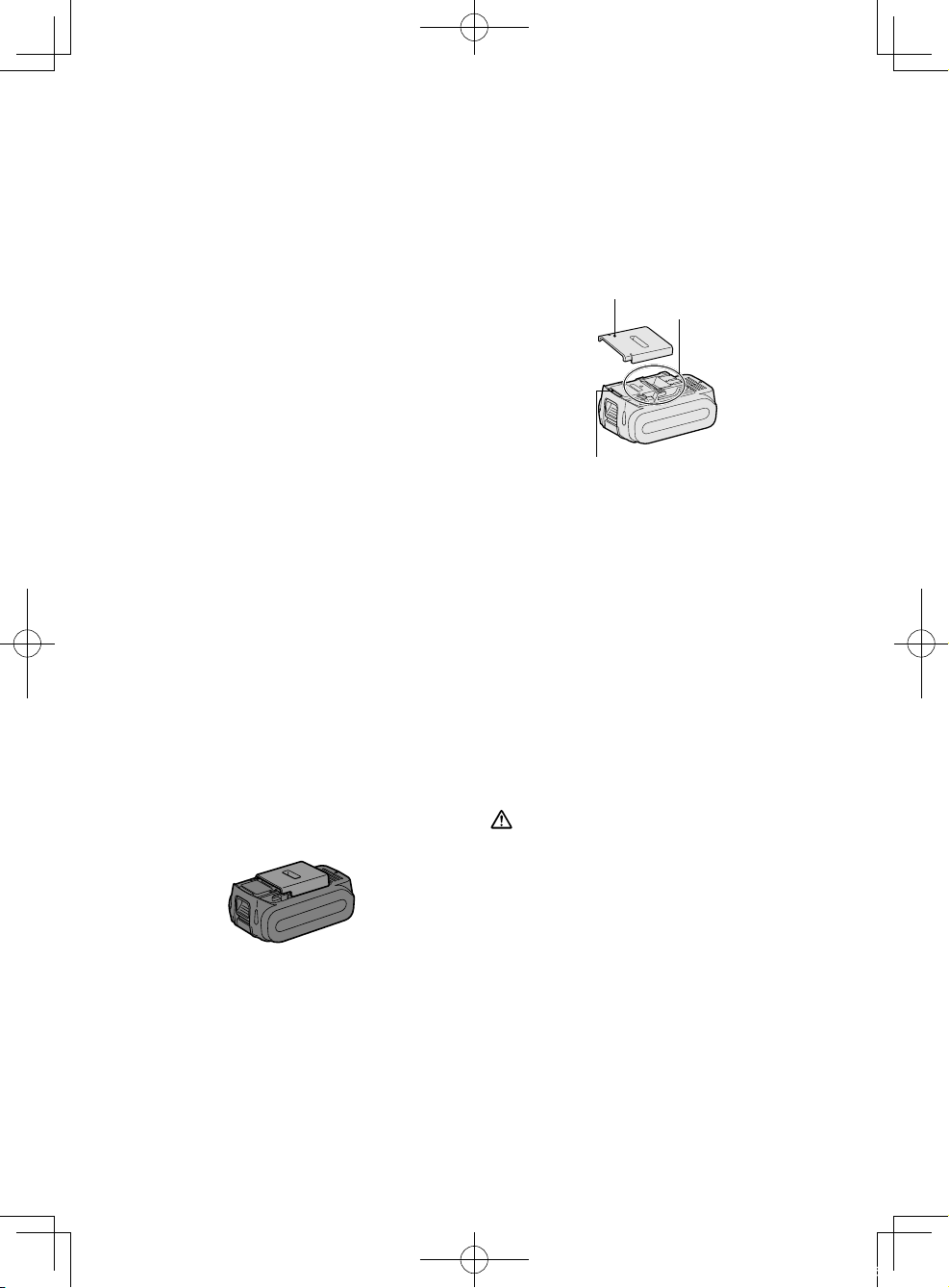
Recommendations for use
Pack cover
Terminals
Label
Be sure to use the Pack cover
• When the battery pack is not being used,
store the battery in a way that foreign
substances such as dust and water etc. do
not contaminate the terminals. Be sure to
attach the battery pack cover to protect the
battery terminals.
• When charging the battery pack, confirm
that the terminals on the battery charger
are free of foreign substances such as dust
and water etc. Clean the terminals before
charging the battery pack if any foreign
substances are found on the terminals.
The life of the battery pack terminals may
be affected by foreign substances such as
dust and water etc. during operation.
CAUTION
To protect the motor or battery, be sure
to note the following when carrying out
operation.
• If the battery becomes hot, the
protection function will be activated
and the battery will stop operating. The
overheat warning lamp on the control
panel illuminates or flashes when this
feature is active.
For safe use
• The battery pack is designed to be installed
by proceeding two steps for safety. Make
sure the battery pack is installed properly to
the main unit before use.
• If the battery pack is not connected firmly
when the switch is switched on, the
-
15 -
01EngEY46A2(EU).indd15 2014/07/0212:01:25
overheat warning lamp and the battery low
warning lamp will flash to indicate that safe
operation is not possible, and the main unit
will not rotate normally. Connect the battery
pack into the unit of the tool until the red or
yellow label disappears.
[Battery Charger]
Charging
CAUTION
• The charger is designed to operate
on standard domestic electrical
power only as stated in the rating
plate. Charge only on the voltage
indicated on the rating plate of unit.
e.g.230V / 50Hz.
• Do not attempt to use it on any other
voltage or frequency rating.
• The ambient temperature range is
between 0°C (32°F) and 40°C (104°F).
• If the battery pack is used when the
battery temperature is below 0°C
(32°F), the tool may fail to function
properly.
• If the temperature of the battery pack
falls approximately below 0°C ( 32°F),
charging will automatically stop to
prevent degradation of the battery.
• Use the charger at temperatures
between 0°C and 40°C, and charge
the battery at a temperature similar
to that of the battery itself. (There
should be no more than a 15°C
difference between the temperatures
of the battery and the charging
location.)
• When charging a cool battery pack
(below 0°C (32°F) in a warm place,
leave the battery pack at the place
and wait for more than one hour to
warm up the battery to the level of
the ambient temperature.
• Cool down the charger when
charging more than two battery
packs consecutively.
• Do not insert your fingers into
contact hole, when holding charger
or any other occasions.
• To prevent the risk of fire or damage
to the battery charger.
1. Do not use power source from an
engine generator.
Unplug the charger when not in
2.
use.
NOTE:
Your battery pack is not fully charged
at the time of purchase. Be sure to
charge the battery before use.
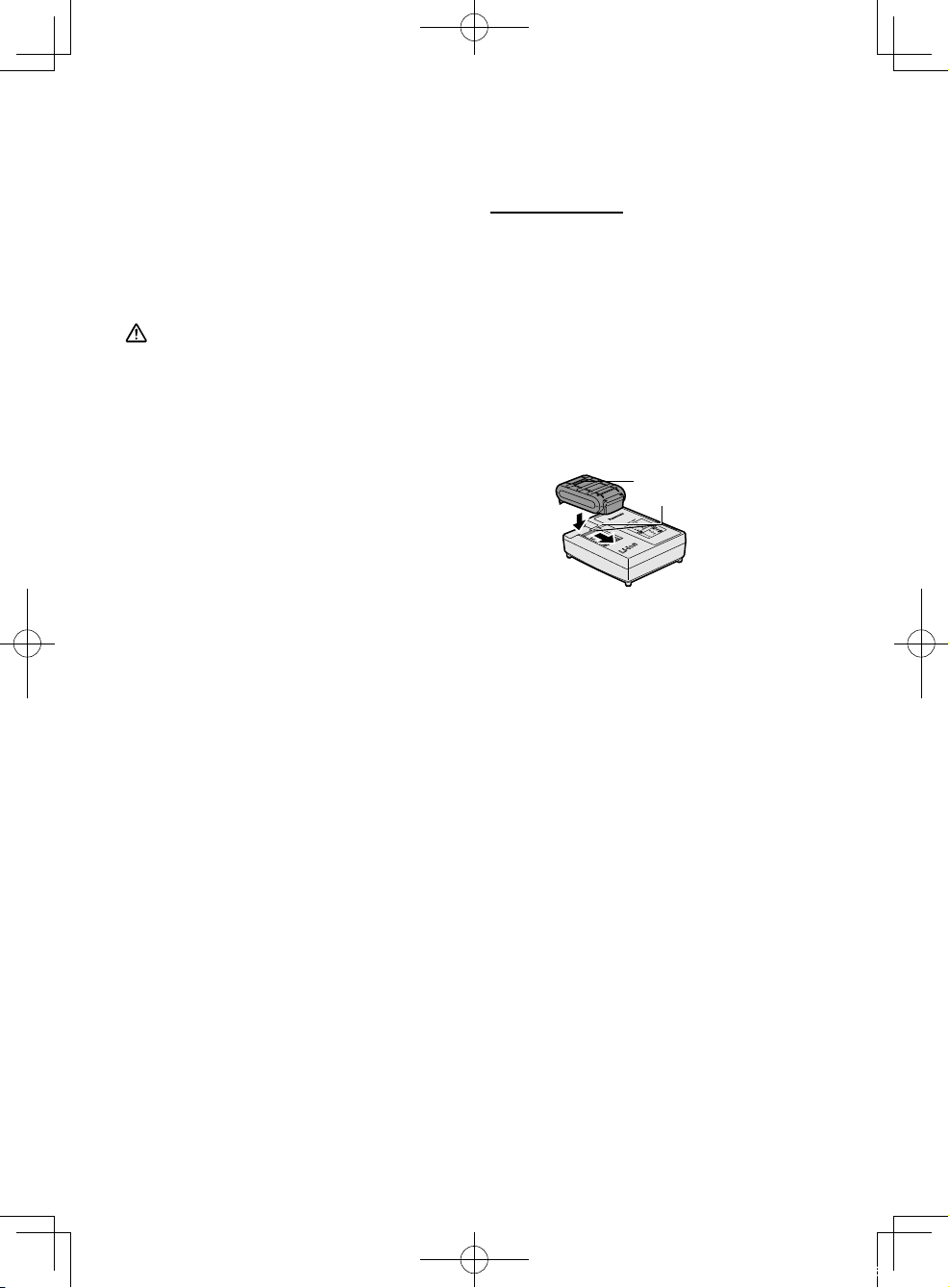
How to charge
1. Plug the charger into the AC outlet.
NOTE:
Sparks may be produced when the plug
is inserted into the AC power supply, but
this is not a problem in terms of safety.
2. Connect the battery pack firmly into the
charger.
1. Line up the alignment marks and
place the battery onto the dock on
the charger.
2. Slide forward in the direction of the
arrow.
Alignment
marks
3. During charging, the charging lamp
will be illuminated. When charging is
completed, an internal electronic switch
will automatically be triggered to prevent
overcharging.
• Charging will not start if the
battery pack is warm (for example,
immediately after heavy-duty
operation).The orange standby
lamp will be flashing until the battery
cools down.Charging will then begin
automatically.
4. The charge lamp (green) will flash
slowly once the battery is approximately
80% charged.
5. When charging is completed, the
charging lamp in green color will turn off.
6. If the temperature of the battery pack
is 0°C or less, charging takes longer to
fully charge the battery pack than the
standard charging time.
Even when the battery is fully charged,
it will have approximately 50% of the
power of a fully charged battery at
normal operating temperature.
7. Consult an authorized dealer if the
charging lamp (green) does not turn off.
8. If a fully charged battery pack is inserted
into the charger again, the charging
lamp lights up. After several minutes, the
charging lamp in green color will turn off.
-
16 -
01EngEY46A2(EU).indd16 2014/07/0212:01:26
LAMP INDICATIONS
Charging is completed. (Full charge.)
Battery is approximately 80% charged.
Now charging.
Charger is plugged into the AC outlet. Ready to charge.
(Green) (Orange)
Turn off Illuminated Flashing
Charging Status Lamp.
Left: green Right: orange will be displayed.
Battery pack is cool.
The battery pack is being charged slowly to reduce the load on the battery.
Battery pack is warm.
Charging will begin when temperature of battery pack drops. If the temperature of the
battery pack is -10° or less, the charging status lamp (orange) will also start flashing .
Charging will begin when the temperature of the battery pack goes up"
Charging is not possible. Clogged with dust or malfunction of the battery pack.
Information for Users on Collection and Disposal of Old
Equipment and used Batteries
These symbols on the products, packaging, and/or accompanying
documents mean that used electrical and electronic products and batteries
should not be mixed with general household waste.
For proper treatment, recovery and recycling of old products and used
batteries, please take them to applicable collection points, in accordance with
your national legislation and the Directives 2002/96/EC and 2006/66/EC.
By disposing of these products and batteries correctly, you will help to save
valuable resources and prevent any potential negative effects on human
health and the environment which could otherwise arise from inappropriate
waste handling.
For more information about collection and recycling of old products and
batteries, please contact your local municipality, your waste disposal service
or the point of sale where you purchased the items.
Penalties may be applicable for incorrect disposal of this waste, in
accordance with national legislation.
For business users in the European Union
If you wish to discard electrical and electronic equipment, please contact your dealer or
supplier for further information.
[Information on Disposal in other Countries outside the European Union]
These symbols are only valid in the European Union. If you wish to discard these items,
please contact your local authorities or dealer and ask for the correct method of disposal.
-
17 -
01EngEY46A2(EU).indd17 2014/07/0212:01:26
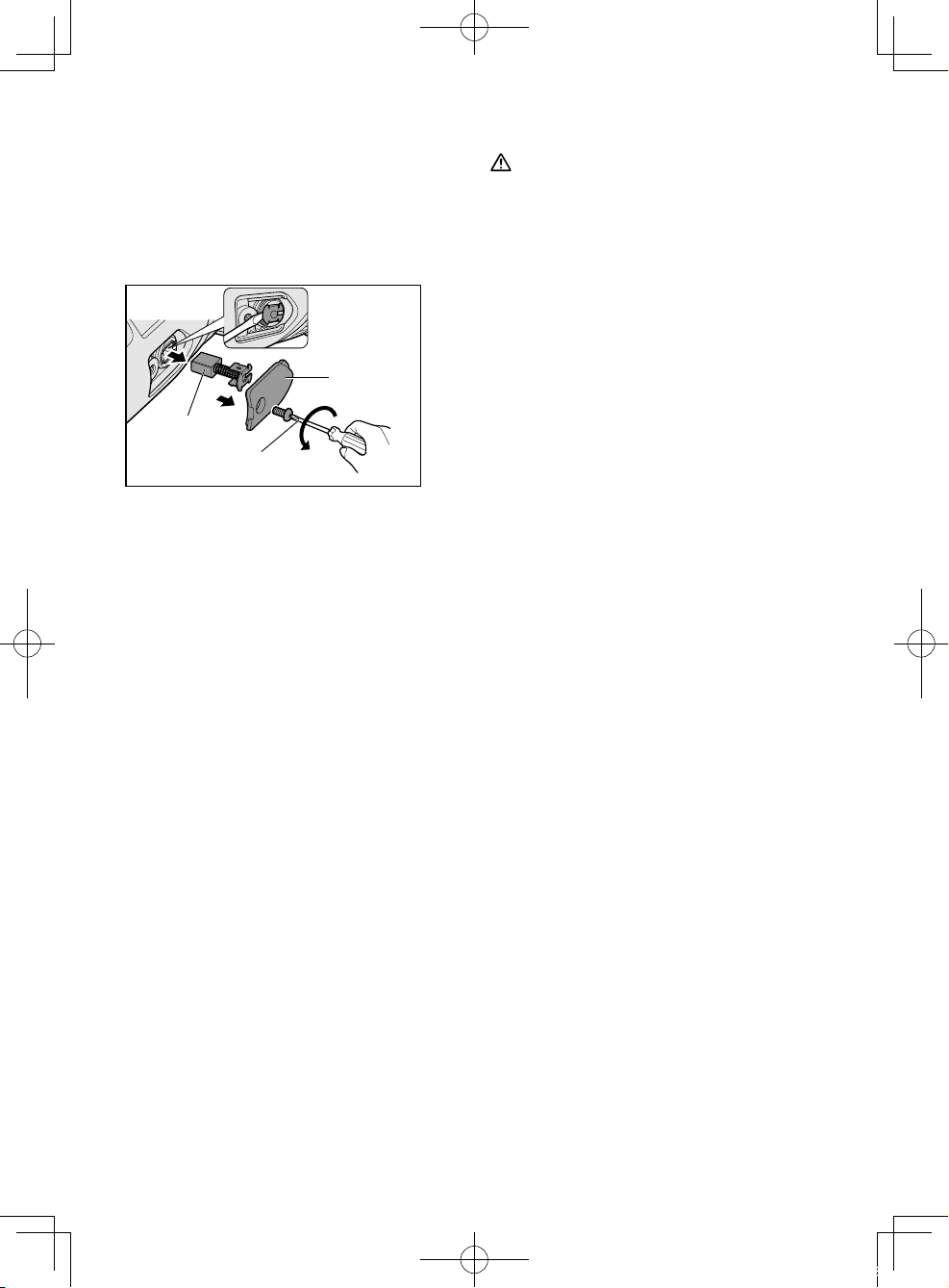
Replacing carbon brushes
Keep the carbon brushes clean and
free to slip in the holders. When it is
less than 5 mm shorter both carbon
brushes should be replaced at the
same time. Use only identical carbon
brushes.
VI. ACCESSORIES
CAUTION
• The use of any accessories not
specified in this manual may
result in fire, electric shock, or
personal injury. Use recommended
accessories only.
• Your tool is supplied with a guard
for use with a grinding disc. A cut-off
disc can also be used with a cut-off
disc guard.
Brush cap
Carbon brush
Screw driver
Use a screwdriver to remove the caps.
Take out the worn carbon brushes,
insert the new ones and secure the
brush caps.
To maintain product SAFETY and
RELIABILITY, repairs, any other
maintenance or adjustment should be
performed by Panasonic Authorized or
Factory Service Centers, always using
Panasonic replacement parts.
V. MAINTENANCE
• Use only a dry, soft cloth for wiping the
unit. Do not use a damp cloth, thinner,
benzine, or other volatile solvents for
cleaning.
• In the event that the inside of the tool or
battery pack is exposed to water, drain
and allow to dry as soon as possible.
Carefully remove any dust or iron
filings that collect inside the tool. If you
experience any problems operating the
tool, consult with a repair shop.
Grinding Disc
• Rated speed: greater than or equal
to 72m/min
• Max. wheel diameter: Φ 125mm
• Hole diameter: Φ 22mm
• Max. thickness: 6mm
Grinding Disc Guard
• WEY46A2K3747
Cut-off Disc
• Rated speed: greater than or equal
to 72m/min
• Max. wheel diameter: Φ125mm
• Hole diameter: Φ 22mm
• Flat disc only
Cut-off Disc Guard (For cut-off disc)
• WEY46A2K3137
Disc Flange
• EY4640K1168
Clamp Nut
• WEY4640K1178
-
18 -
01EngEY46A2(EU).indd18 2014/07/0310:11:03
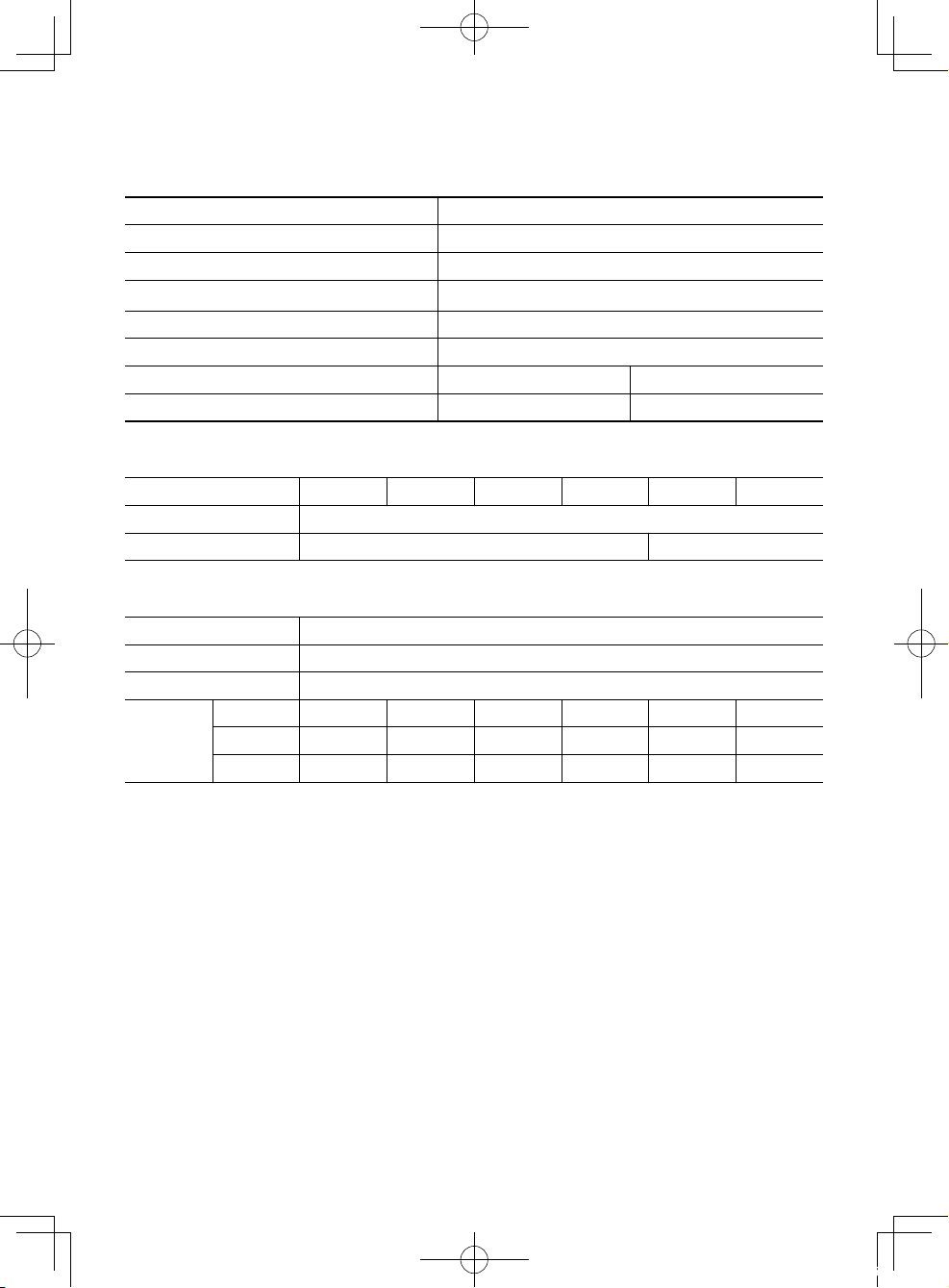
VII. SPECIFICATIONS
MAIN UNIT
Mounting wheel diameter Φ125 mm
Spindle thread size M14
Mounting wheel hole diameter 22 mm
Weight 1.65 kg (main unit only)
Overall length 300 mm (main unit only)
Noise, Vibration See the included sheet
Motor voltage DC 14.4 V DC 18 V
Rated speed 8000min
BATTERY PACK
-1
(rpm) 10000min-1 (rpm)
Model No.
Storage battery Li-ion Battery
Battery voltage DC 14.4 V DC 18 V
EY9L41 EY9L42 EY9L44 EY9L45 EY9L50 EY9L51
BATTERY CHARGER
Model No. EY0L82
Electrical rating See the rating plate on the bottom of charger
Weight 0.93 kg
Charging
time
NOTE: This chart may include models that are not available in your area.
Model No.
Usable 35 min. 30 min. 40 min. 50 min. 40 min. 55 min.
Full 50 min. 35 min. 55 min. 60 min. 55 min. 70 min.
Please refer to the latest general catalogue.
For the dealer name and address, please see the included warranty card.
EY9L41 EY9L42 EY9L44 EY9L45 EY9L50 EY9L51
VIII. APPENDIX
WARRANTY SUPPLEMENT
• The breakdown and damage caused by usage consistent for a long time (e.g.:
factory work on the assembly line, etc.) is out of warranty.
• Damage or failure caused by use of accessories that are not specified in this
manual will not be covered by warranty.
-
19 -
01EngEY46A2(EU).indd19 2014/07/0212:01:27
ONLY FOR U.K.
IX. ELECTRICAL
PLUG INFORMATION
FOR YOUR SAFETY PLEASE READ
THE FOLLOWING TEXT CAREFULLY
This appliance is supplied with a moulded
three pin mains plug for your safety and
convenience.
A 5 amp fuse is fitted in this plug.
Should the fuse need to be replaced
please ensure that the replacement
fuse has a rating of 5 amp and that it is
approved by ASTA or BSI to BS1362.
IMPORTANT:
The wires in this mains lead are
coloured in accordance with the
following code:
Blue: Neutral
Brown: Live
As the colours of the wire in the mains
lead of this appliance may not correspond
with the coloured markings identifying the
terminals in your plug, proceed as follows.
The wire which is coloured BLUE must be
connected to the terminal in the plug which
is marked with the letter N or coloured
BLACK.
The wire which is coloured BROWN
must be connected to the terminal in the
plug which is marked with the letter L or
coloured RED.
Under no circumstances should either
of these wires be connected to the earth
terminal of the three pin plug, marked with
the letter E or the Earth Symbol
.
Check for the ASTA mark
mark
If the plug contains a removable fuse cover
you must ensure that it is refitted when the
fuse is replaced.
If you lose the fuse cover the plug must
not be used until a replacement cover is
obtained.
A replacement fuse cover can be
purchased from your local Panasonic
Dealer.
IF THE FITTED MOULDED PLUG IS
UNSUITABLE FOR THE SOCKET
OUTLET IN YOUR HOME THEN THE
FUSE SHOULD BE REMOVED AND THE
PLUG CUT OFF AND DISPOSED OF
SAFELY.
THERE IS A DANGER OF SEVERE
ELEC¬TRICAL SHOCK IF THE CUT OFF
PLUG IS INSERTED INTO ANY 13 AMP
SOCKET.
If a new plug is to be fitted please observe
the wiring code as shown below.
If in any doubt please consult a qualified
electrician.
on the body of the fuse.
or the BSI
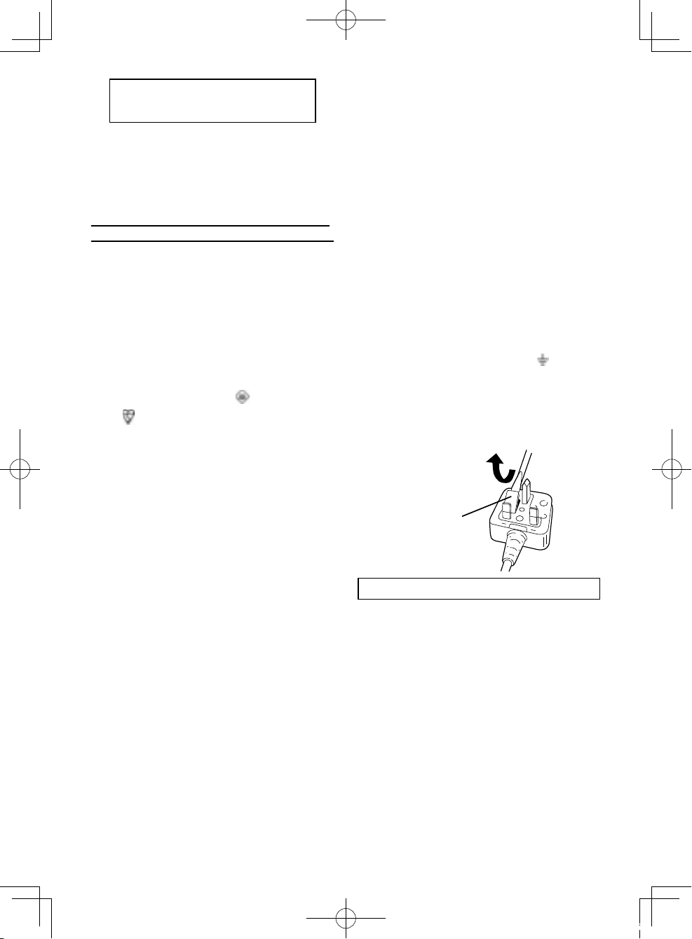
How to replace the fuse: Open the fuse
compartment with a screwdriver and
replace the fuse and fuse cover if it is
removable.
Fuse Cover
This apparatus was produced to BS800.
-
20 -
01EngEY46A2(EU).indd20 2014/07/0212:01:27
Original-Anleitung: Englisch
Übersetzung der Original-Anleitung:
Andere Sprachen
I.
BESTIMMUNGSGEMÄSSE
WARNUNG
Zur Verminderung der Verletzungsgefahr
müssen zum Schleifen immer die
richtigen Schutze verwendet werden.
Hinweise zu dieser Anleitung
VERWENDUNG DER
MASCHINE
Vielen Dank, für den Kauf des
Panasonic-Winkelschleifers. Die
hervorragende Schleifleistung erfüllt
höchste Anforderungen und die
Unabhängigkeit von Netzanschlüssen
erlaubt einen vielseitigen Einsatz.
Dieser Winkelschleifer ist
ausschließlich für das Schleifen und
Trennschleifen vorgesehen.
GEFAHR
Dieses Gerät ist ein Schleifwerkzeug
zum Schleifen. Durch die Schleifscheibe
können äußerst tiefe und sogar
lebensgefährliche Schnittverletzungen
verursacht werden. Lesen Sie daher
unbedingt diese Anleitung und die
Vorsichtshinweise auf dem Werkzeug
sorgfältig durch, und beachten Sie
alle Sicherheitsvorschriften und die
zusätzlichen Vorschriften, um solche
Verletzungen zu vermeiden.
HINWEIS:
VORSICHT
Verweist auf potentielle
Gefahrensituationen, die bei Missachtung
der gegebenen Warnhinweise geringere
Verletzungen zur Folge haben können.
Solche Textstellen warnen außerdem vor
gefährlichen Vorgehensweisen.
• Bitte lesen Sie sich diese Anleitung
vor der Inbetriebnahme des
Winkelschleifers vollständig durch.
Falls eine weitere Person diesen
Winkelschleifer verwendet, sollten
Sie darauf achten, dass auch diese
Person zuvor diese Anleitung liest oder
im Gebrauch des Winkelschleifers und
den Vorsichtsmaßregeln unterwiesen
wurde.
• Diese Anleitung zum späteren
Nachschlagen an einem sicheren Ort
aufbewahren. Sie enthält wichtige
Sicherheitshinweise, die beim Betrieb
des Winkelschleifers zu beachten sind.
• In dieser Anleitung und auf dem
Produkt finden Sie folgende
Signalwörter:
Gibt zusätzliche, nützliche
Informationen zur Winkelschleifer.
WARNUNG
Verweist auf potentielle Gefahren,
die bei Missachtung der gegebenen
Warnhinweise zu schweren
Verletzungen oder Tod führen können.
GEFAHR
Verweist auf eine Gefahr, die
bei Missachtung der gegebenen
Warnhinweise zu ernsten Verletzungen
oder Tod führt.
-
21 -
02GerEY46A2(EU).indd211 2014/07/0212:02:07

Lesen Sie bitte vor der ersten Inbetriebnahme
dieses Geräts das separate Handbuch
„Sicherheitsmaßregeln“ sorgfältig durch.
II.
WEITERE WICHTIGE
SICHERHEITSREGELN
Sicherheitsanweisungen für
alle Bedienungen
Allgemeine Sicherheitshinweise zum
Schleifen und Trennschleifen:
1) Dieses Elektrowerkzeug ist für
den Einsatz als Schleif-oder
Trennschleifmaschine vorgesehen.
Lesen Sie bitte alle diesem
Elektrowerkzeug beiliegenden
Warnungen, Anweisungen,
Abbildungen und technischen
Daten. Bei Nichtbeachtung der
nachstehenden Anweisungen ist die
Gefahr eines elektrischen Schlags,
eines Brandausbruchs oder von
schweren Verletzungen vorhanden.
2)
Es wird nicht empfohlen
Bedienungen wie das
Sandpapierschleifen, Bürsten
oder Polieren mit diesem
Elektrowerkzeug vorzunehmen.
Anwendungen, für welche das
Elektrowerkzeug nicht vorgesehen ist,
können gefährliche Situationen und
Verletzungen verursachen.
3) Nur speziell gefertigtes und vom
Werkzeughersteller empfohlenes
Zubehör verwenden. Wenn sich
ein Zubehör am Elektrowerkzeug
anbringen lässt, ist damit noch kein
sicherer Betrieb garantiert.
4) Die Nenndrehzahl des
Zubehörs muss mindestens
der Maximaldrehzahl des
Elektrowerkzeugs entsprechen.
Falls das Zubehör mit höherer als der
NENNDREHZAHL betrieben wird,
kann es beschädigt werden.
5) Der Außendurchmesser und die
Dicke des Zubehörs müssen
innerhalb der Spezifikationen
des Elektrowerkzeugs liegen. Für
Zubehör in einer unzulässigen Größe
ist kein ausreichender Schutz bzw.
Kontrolle möglich.
6)
Die Gewindehalterung des
Zubehörs muss mit dem Gewinde
der Spindel des Winkelschleifers
übereinstimmen. Bei Zubehör, das
mit Flanschen befestigt wird, muss
das Zubehörloch in den Durchmesser
des Flansches passen. Zubehör,
das mit der Montagehardware des
Elektrowerkzeugs nicht übereinstimmt,
verursacht Unwucht, starke Vibrationen
und kann zu Kontrollverlust führen.
7) Kein beschädigtes Zubehör
verwenden. Vor jeder
Inbetriebnahme muss das
Zubehör, wie die Schleifscheiben
auf Splitterung und Risse
kontrolliert werden. Falls das
Elektrowerkzeug oder das Zubehör
fallen gelassen wurde, müssen
die Teile auf Beschädigung
überprüft bzw. ein unbeschädigtes
Zubehör verwendet werden. Nach
abgeschlossener Prü-fung und
Installation des Zubehörs müssen
Sie sich und die Zuschauer
außerhalb des Bereichs der Ebene
der rotieren-den Scheibe begeben
und das Elektrowerkzeug bei
Maximaldrehzahl ohne Belastung
für eine Minute lang einschalten.
Beschädigtes Zubehör bricht
normalerweise während dieser
Testzeit auseinander.
8)
Schutzvorrichtungen verwenden. Je
nach Anwendung muss ein Gesichtsschutzschild oder eine Schutzbrille
getragen werden. Außerdem nach
Bedarf eine Staubschutzmaske,
einen Gehörschutz, Handschuhe
oder eine Schürze tragen, die
kleine Fragmente des Werkstücks
aufzufangen vermögen. Der
Augenschutz muss in der Lage
sein, weg geschleuderte Fragmente
von verschiedenen Anwendungen
aufzufangen. Die Staubmaske
bzw. das Atemgerät muss die
entstehenden Staubpartikel wirksam
herausfiltern können. Eine langzeitige
Einwirkung lauter Geräusche kann zu
Gehörschäden führen.
9) Zuschauer sollten sich in sicherer
Entfernung vom Arbeitsbereich
aufhalten. Personen, die sich
-
22 -
02GerEY46A2(EU).indd212 2014/07/0212:02:07

in den Arbeitsbereich begeben,
müssen entsprechende
Schutzvorrichtungen verwenden.
Weggeschleuderte Fragmente vom
Werkstück oder von beschädigtem
Zugehör können auch außerhalb
des unmittelbaren Arbeitsbereichs
Verletzungen verursachen.
10)
Halten Sie das Elektrowerkzeug nur
an den Oberflächen der Isoliergriffe
fest, wenn Sie Arbeiten ausführen,
bei denen das Schneidwerkzeug
auf verborgene Kabel treffen kann.
Durch die Berührung eines unter
Spannung stehenden Kabels können
die Metallteile des Elektrowerkzeugs
unter Strom gesetzt werden und der
Bediener kann einen elektrischen
Schlag erleiden.
11)
Das Netzkabel entfernt von dem sich
drehenden Zubehör verlegen. Bei
einem Kontrollverlust kann das Kabel
durchgeschnitten oder Ihre Hand oder
Ihr Arm kann in das sich drehende
Zubehör hineingezogen werden.
12) Das Elektrowerkzeug niemals
ablegen, solange es sich noch
dreht. Das sich drehenden
Zubehör kann hängen bleiben und
das Elektrowerkzeug kann außer
Kontrolle geraten.
13) Das Elektrowerkzeug beim
Herumtragen nicht eingeschaltet
lassen. Durch eine unfreiwillige
Berührung mit der Bekleidung
kann das Zubehör an Ihren Körper
gezogen werden.
14) Die Luftauslassöffnungen des
Elektrowerkzeugs müssen in
regelmäßigen Abständen gereinigt
werden. Das Gebläse des Motors
kann Staub ansaugen und wenn sich
im Gehäuse Metallstaub ansammelt,
besteht eine große Gefahr.
15)
Verwenden Sie das Elektrowerkzeug
nicht in der Nähe von leicht
entzündbaren Materialien. Solche
Materialien können durch Funken
entzündet werden.
16) Kein Zubehör verwenden, das
flüssige Kühlmittel benötigt.
Bei Verwendung von Wasser oder
anderen flüssigen Kühlmitteln
besteht die Gefahr eines elektrischen
Schlags.
Weitere Sicherheitsanweisungen
für alle Anwendungen
Rückstoß und entsprechende
Warnungen
Der Rückstoß ist die Reaktion auf eine
eingeklemmte oder blockierte Scheibe,
Unterlage, Bürste oder eines anderen
Zubehörs. Durch das Einklemmen
oder Blockieren wird die Drehung des
Zubehörs sofort gestoppt und dadurch
entsteht eine Reaktionskraft auf die
Gegenseite der Drehrichtung des
Zubehörs am Eingriffspunkt.
Falls zum Beispiel die Schleifscheibe
durch das Werkstück eingeklemmt
oder blockiert wird, kann die Kante
der Scheibe am Eingriffspunkt in
das Material eindringen, was die
Rückstoßkraft erzeugt. Je nach
Bewegungsrichtung kann die
Scheibe am Eingriffspunkt gegen den
oder vom Bediener weg springen.
Schleifscheiben können unter diesen
Bedingungen auch brechen.
Rückstöße entstehen bei
Missbrauch oder Fehlbedienung
des Elektrowerkzeugs und deren
Bedienungen. Falls die richtigen
Vorsichtsmaßnahmen wie nachstehend
aufgeführt getroffen werden, lassen
sich Rückstöße vermeiden.
1) Das Elektrowerkzeug muss fest
gehalten werden, Rückstoßkräfte
sollen durch den Körper und die
Arme aufgefangen werden können.
Der Hilfsgriff, falls vorhanden,
muss immer verwendet werden,
um die Kontrolle bei auftretenden
Rückstoß- und Drehkräften beim
Einschalten nicht zu verlieren.
Der Bediener kann Rückstoß- und
Drehkräfte unter Kontrolle halten, wenn
die richtigen Vorsichtsmaßnahmen
getroffen werden.
2) Die Hand darf niemals in die
Nähe des sich drehenden
Zubehörs gehalten werden. Bei
Rückstoßkräften kann die Hand vom
Zubehör getroffen werden.
-
23 -
02GerEY46A2(EU).indd213 2014/07/0212:02:07

3) Der Körper darf sich nicht in dem
Bereich befinden, in den sich das
Elektrowerkzeug bei auftretenden
Rückstoßkräften bewegt. Durch
den Rückstoß wird das Tool beim
Blockieren in die Gegenrichtung der
Scheibenbewegung gedrückt.
4) Besondere Vorsicht muss bei
Ecken, Kanten usw. angewendet
werden. Das Zubehör darf nicht
anschlagen oder blockiert werden.
Bei Ecken und scharfen Kanten
besteht die Gefahr, dass das sich
drehende Zubehör blockiert wird
und durch die Rückstoßkräfte eine
Kontrollverlust auftritt.
5) Kein Kettensägeblatt oder ein
gezähntes Sägeblatt anbringen.
Solche Blätter verursachen häufig
Rückstoßkräfte, die zu einem
Kontrollverlust führen können.
Zusätzliche Sicherheitsanweisungen zum Schleifen und
Trennschleifen
Spezielle Sicherheitshinweise zum
Schleifen und Trennschleifen:
1) Nur die für das Elektrowerkzeug
empfohlenen Scheiben und
den zur verwendeten Scheibe
entsprechende Schutz verwenden.
Für Scheiben, die nicht geeignet
sind, ist keine entsprechende
Schutzvorrichtung vorhanden,
deshalb gelten diese als unsicher.
2) Die Schleifoberfläche der
mittig eingesetzten Scheiben
muss unterhalb der Ebene der
Schutzlippe eingesetzt werden.
Eine unsachgemäß angebrachte
Scheibe, die durch die Ebene der
Schutzlippe herausragt, kann nicht
ausreichend gesichert werden.
3) Der Schutz muss richtig am
Elektrowerkzeug angebracht
werden und für maximale
Sicherheit positioniert werden,
so dass möglichst ein kleiner
Teil der Scheibe gegen den
Bediener schaut. Der Schutz hilft
dem Bediener zum Schutz vor
zerbrochenen Scheibenteilen und
der versehentlichen Berührung der
Scheibe und vor Funken, die die
Kleidung entzünden können.
4)
Die Scheiben dürfen nur für die
empfohlenen Anwendungen
verwendet werden. Zum Beispiel:
Die Seite der Trennscheibe darf nicht
zum Schleifen verwendet werden.
Trennscheiben sind zum Schleifen
am Scheibenumfang, bei Belastung
solcher Scheiben mit Seitenkräften
können die Scheiben brechen.
5)
Nur unbeschädigte
Scheibenflanschen mit der für die
verwendete Scheibe passenden Größe
und Form verwenden. Die Scheibe wird
zur Verringerung von Scheibenbrüchen
durch die richtigen Scheibenflansche
gestützt. Die Flansche für Trennscheiben
können sich von Flanschen für
Schleifscheiben unterscheiden.
6)
Keine abgenutzten Scheiben von
größeren Elektrowerkzeugen
verwenden. Die Scheiben für größere
Elektrowerkzeuge sind nicht geeignet
für die höheren Drehzahlen der
kleineren Tools und können brechen.
Zusätzliche Sicherheitsanweisungen
zum Trennschleifen:
1)
Die Trennscheibe darf nicht
eingeklemmt oder mit übermäßigen
Kräften belastet werden. Nicht
ver-suchen eine übermäßige
Schnitttiefe zu erreichen. Eine
Überbeanspruchung der Scheibe
führt zu einer erhöhten Belastung
und die Möglichkeit eines Verdrehens
oder Blockierens im Schnitt erhöht
sich, was zu Rückstoßkräften oder zu
einem Scheibenbruch führen kann.
2) Der Körper darf sich nicht in einer
Linie oder hinter der Scheibe
befinden. Wenn im Betrieb die
Scheibe vom Körper weg bewegt
wird, erfolgt ein möglicher Rückstoß
des Elektrowerkzeugs direkt gegen
den Körper.
3)
Bei blockierter Scheibe oder bei einer
-
24 -
02GerEY46A2(EU).indd214 2014/07/0212:02:07
Unterbrechung des Trennschleifens
muss das Elektrowerkzeug
ausgeschaltet und still gehalten
werden, bis sich die Scheibe
nicht mehr dreht. Nicht versuchen
die Trennscheibe in drehendem
Zustand zu entfernen, weil dabei
ein Rückstoß auftreten kann. Die
Ursache der Scheibenblockierung
herausfinden und beheben.
4) Beim Fortsetzen darf sich die
Trennscheibe nicht im Werkstück
befinden. Die Scheibe muss
die volle Drehzahl erreicht
haben, bevor sie ins Werkstück
eingeführt wird. Wenn sich beim
Start die Scheibe im Werkstück
befindet, können Rückstoßkräfte
auftreten.
5) Platten oder große Werkstücke
müssen zur Verminderung der
Einklemmgefahr und möglicher
Rückstoßkräfte gestützt werden.
Große Werkstücke können durch
das Eigengewicht durchhängen.
Deshalb müssen sie in der
Nähe der Trennlinie an beiden
Werkstückkanten gestützt werden.
6) Für einen „Taschenschnitt“
in bestehenden Wänden oder
anderen Blindbereichen muss
besondere Vorsicht angewendet
werden. Die vorstehende Scheibe
kann Gas- oder Wasserleitungen,
elektrische Kabel oder Gegenstände
trennen, was Rückstoßkräfte
verursachen kann.
Symbol Bedeutung
V Volt
Gleichstrom
n Nenndrehzahl
… min
Ah
pro Minute
Akkukapazitat in Ampere
Stunden
Drehzahl oder Hubzahl
-1
Zur Verminderung der
Verletzungsgefahr muss
die Bedienungsanleitung
gründlich gelesen werden.
Nur für Inneneinsatz.
Immer einen
Augenschutz tragen
WARNUNG
• Verwenden Sie nur die
PanasonicAkkus, die für den Einsatz
mit dieser Akku-Maschine ausgelegt
sind.
• Panasonic übernimmt keine
Verantwortung für etwaige Schäden
oder Unfälle, die durch den Gebrauch
von recycelten und gefälschten
Akkus verursacht werden.
• Werfen Sie den Akku nicht ins Feuer,
und setzen Sie ihn auch keiner
übermäßigen Wärme aus.
• Unterlassen Sie das Einschlagen
von Nägeln in den Akku sowie
Erschüttern, Zerlegen oder
Abändern des Akkus.
• Achten Sie darauf, dass keine
Metallgegenstände mit den Kontakten
des Akkus in Berührung kommen.
• Unterlassen Sie das Tragen oder
Aufbewahren des Akkus zusammen
mit Nägeln oder ähnlichen
Metallgegenständen im selben
Behälter.
• Laden Sie den Akku nicht an einem
heißen Ort, wie z. B. in der Nähe
eines Feuers oder in direktem
Sonnenlicht. Anderenfalls kann der
Akku überhitzen, Feuer fangen oder
explodieren.
• Verwenden Sie nur das zugehörige
Ladegerät zum Laden des
Akkus. Anderenfalls kann der
Akku auslaufen, überhitzen oder
explodieren.
• Nachdem Sie den Akku von der
Maschine oder dem Ladegerät
abgenommen haben, bringen Sie
stets die Akkuabdeckung wieder an.
Anderenfalls könnten die Akkukontakte
kurzgeschlossen werden, was zu
einem Brand führen kann.
• Wenn der Akku schwach geworden
ist, ersetzen Sie ihn durch einen
neuen. Fortgesetzter Gebrauch
eines beschä-digten Akkus kann zu
Wärmeerzeugung, Entzündung oder
Bruch führen.
-
25 -
02GerEY46A2(EU).indd215 2014/07/0212:02:08
III. BAUGRUPPE
HINWEIS:
Wenn Sie einen Zusatzgriff anbringen
oder entfernen, nehmen Sie den
Akkupack aus dem Werkzeug heraus.
VORSICHT
• Bei der Verwendung muss der
Schleifscheibenschutz immer am
Tool installiert sein, so dass die
geschlossene Seite des Schutzes
gegen den Bediener gerichtet ist.
• Stellen Sie sicher, dass
Beilegscheiben verwendet werden,
wenn diese mit Schleifscheiben
aus gebundenem Schleifmittel
mitgeliefert werden und wenn diese
erforderlich sind;
VORSICHT
Achten Sie stets darauf, dass der
Zusatzgriff sicher montiert ist, bevor
Sie mit der Arbeit beginnen.
• Den Seitengriff wie in der Abbildung gezeigt
richtig einschrauben.
VORSICHT
Bei sich drehender Spindel darf der Sicherungsstift niemals betätigt werden.
Das Tool kann dabei beschädigt werden.
• Die Verriegelungstaste drücken, wenn
sich die Spindel nicht drehen soll, wie
zum Ein- oder Ausbau von Teilen wie
Schleifscheiben, Scheibenschutz usw.
Installieren und Entfernen der
Scheibe
Prüfung vor der Inbetriebnahme
• Ist die richtige Schleifscheibe für
den zu schneidenden Gegenstand
eingesetzt?
• Ist eine Schleifscheibe der richtigen
Größe eingesetzt?
• Ist die richtige Scheibe entsprechend
der nachfolgend benannten
Sicherheitsnormen angebracht?
Europa - EN, Australien - AS
WARNUNG
Zum Trennschleifen muss immer der
mitgelieferte Schutz verwendet werden.
Die Schleifscheibe kann während der
Anwendung brechen und mit dem
Schleifscheibenschutz lässt sich die
Verletzungsgefahr vermindern.
1. Den Schleifscheibenschutz installieren
und die Schraube richtig festziehen.
1. Mutter
1
Auf die richtige
Richtung der
Seite achten.
2. Den Scheibenflansch und die Scheibe
in der abgebildeten Reihenfolge auf die
Spindel setzen.
3.
Die Mutter auf der Spindel festziehen,
so dass die gewölbte Seite auf die
Gegenrichtung der Scheibe gerichtet ist.
4. Die Spindelverriegelungstaste
hineindrücken, um die Spindel
festzustellen und die Mutter mit dem
Klemmenmutterschlüssel festziehen.
Spindelverriegelungstaste
2. Schleifscheibe
3. Scheibenflansch
2
3
1. Schleifschei-
1
benschutz
2. Spindel
2
Schleifscheibens-
3.
3
chutzschraube
-
26 -
02GerEY46A2(EU).indd216 2014/07/0212:02:12
IV. BETRIEB
HINWEIS:
Weil kein Anschluss an einer Netzsteckdose
notwendig ist, befindet sich dieses Tool
immer in betriebsbereitem Zustand.
5. Zum Entfernen der Schleifscheibe die
Installationsschritte in der umgekehrten
Reihenfolge ausführen.
Anbringen oder Abnehmen
des Akkus
VORSICHT
Vergewissern Sie sich vor dem Einsetzen
des Akkus, dass der Ein-Aus-Schalter
der Maschine einwandfrei funktioniert
und beim Loslassen zur Position „OFF“
zurückkehrt.
1. Zum Anschließen des Akkus:
Die Ausrichtmarkierungen aufeinander
ausrichten, und den Akku anbringen.
• Den Akku einschieben, bis er
einrastet.
Ausrichtmarkierungen
2. Zum Entfernen des Akkus:
Den Knopf nach unten drücken und den
Akku nach vor schieben.
Einschalterbedienung
VORSICHT
• Vor dem Einsetzen des Akkus in das
Tool muss geprüft werden, ob sich der
Einschalter richtig bedienen lässt und in
die Position „AUS“ zurückkehrt, wenn er
hintere Schalterteil gedrückt wird.
• Der Einschalter kann in der „EIN“Position
festgestellt werden. Passen Sie beim
Feststellen des Einschalters in der
„EIN“-Position auf und halten Sie den
Stützgriff und den Griff richtig fest.
Drücken Sie den Einschalter zum Einschalten
und schieben Sie ihn gegen die „EIN“-Position.
Drücken Sie für einen kontinuierlichen Betrieb die
vordere Seite des Einschalters zum Feststellen.
Knopf
-
27 -
02GerEY46A2(EU).indd217 2014/07/0212:02:15
Um das Werkzeug anzuhalten, drücken
Sie auf die Rückseite des Netzschalters,
dann kehrt dieser wieder in die Position
„AUS“ zurück.
WARNUNG
• Auf das Tool sollte keine
übermäßigen Kräfte angewendet
werden. Das Gewicht des Tools
erzeugt einen ausreichenden
Druck. Durch Kraftanwendung und
übermäßigen Druck kann ein Bruch
der Schleifscheibe verursacht
werden.
• Falls das Tool beim Schleifen
fallen gelassen wurde, muss die
Schleifscheibe IMMER ausgetauscht
werden.
• Die Schleifscheibe darf nicht
angeschlagen werden.
• Vermeiden Sie das Hüpfen oder
Blockieren der Schleifscheib,
besonders beim Arbeiten an Ecken,
scharfen Kanten usw. Dadurch
kann ein Verlust der Kontrolle
verursacht werden und es können
Rückstoßkräfte auftreten.
VORSICHT
Schalten Sie am Ende das Tool immer
aus und warten Sie bis sich die Scheibe
nicht mehr dreht, bevor Sie das Tool
ablegen.
Sichtprüfung und
Scheibenbetriebsprüfung
1. Kontrollieren Sie vor der Inbetriebnahme
immer, ob die Scheibe keine Risse
aufweist.
2. Führen Sie immer die folgende
Betriebsprüfung aus.
3. Die Scheibe muss immer richtig
befestigt werden.
Zeit
Neue Scheibe mehr als 3 Min.
Vor Verwendung
der gegenwärtigen
mehr als 1 Min.
Scheibe
Schleifen
°
B
Halten Sie das Werkzeug IMMER mit
der einen Hand am Griff und mit der
anderen am Zusatzgriff fest. Schalten
Sie das Werkzeug ein und halten Sie
die Scheibe an das Werkstück.
Halten Sie im allgemeinen die
Schleifscheibe in einem Winkel von
ungefähr 15°-30° zur Werkstückoberfläche.
Bei Verwendung einer neuen
Schleifscheibe darf der Winkelschleifer
nicht in Richtung B bewegt werden, weil
sonst das Werkstück angeschnitten
wird. Nachdem die Kanten der
neuen Schleifscheibe durch die
Verwendung abgerundet sind, kann die
Schleifscheibe in beiden Richtungen A
und B verwendet werden.
15°~30
A
-
28 -
02GerEY46A2(EU).indd218 2014/07/0212:02:17
Trennscheibenschutz
(als Sonderzubehör erhältlich)
1. Mutter
1
Trennscheibe
2
3
4
2.
3.
4. Spindel
Schleifscheibe
Auf die richtige Richtung
der Seite achten.
WARNUNG
• Bei Verwendung einer Trennscheibe
muss der entsprechende
Trennscheibenschutz verwendet werden.
• Eine Trennscheibe darf NIEMALS zum
Schleifen verwendet werden.
• Die Trennscheibe darf nicht eingeklemmt
oder mit übermäßigen Kräften belastet
werden. Nicht versuchen eine übermäßige
Schnitttiefe zu erreichen. Eine
Überbeanspruchung der Trennscheibe
führt zu einer erhöhten Belastung
und die Möglichkeit eines Verdrehens
oder Blockierens im Schnitt und einer
Motorüberhitzung erhöht sich.
• Nicht einschalten, wenn sich die
Scheibe im Werkstück befindet. Dadurch
kann die Trennscheibe blockiert
werden und es können Rückstoßkräfte
auftreten. Die Scheibe muss die volle
Drehzahl erreicht haben, bevor sie ins
Werkstück eingeführt wird.
• Während des Trennschleifens
darf der Winkel der Scheibe nicht
geändert werden. Bei Anwendung von
Seitenkräften (wie beim Schleifen) auf
die Trennscheibe kann die Scheibe
reißen und brechen, so dass eine hohe
Verletzungsgefahr vorhanden ist.
zu einem Ausfall führen kann.
• Überlasten Sie den Motor des
Werkzeugs nicht. Hierdurch kann die
Maschine beschädigt werden.
• Halten Sie das Tool so, dass die
Abluft von den Ventilationsöffnungen
im Gehäuse nicht direkt gegen Ihre
Haut geblasen wird. Anderenfalls
können Sie sich verbrennen.
Anzeigelampe für die
Einschaltsicherungsfunktion
Der Winkelschleifer startet nicht, wenn
der Akkupack eingesetzt ist, wenn
sich der Schalter in der Position EIN
befindet (Schalterhebel auf EIN). Die
Warnleuchte blinkt zu diesem Zeitpunkt,
um anzuzeigen, dass die ‚Einschaltsicherungsfunktion’ betätigt wurde.
Stellen Sie den Schalter in die Position
„AUS“ (Schalterhebel auf „AUS“) und
drücken Sie den Schalter wieder in die
Position „EIN“ (Schalterhebel auf „EIN“)
zurück.
AUS→EIN EIN→AUS
VORSICHT
• Um übermäßigen Temperaturanstieg
der Werkzeugoberfläche zu vermeiden,
sollte das Werkzeug nicht kontinuierlich
mit zwei oder mehr Akkus betrieben
werden. Das Werkzeug muss vor dem
Akkuwechsel abkühlen.
• Blockieren Sie nicht die seitlichen Ventilationsöffnungen des Gehäuses während
des Betriebs. Anderenfalls wird die
Maschinenfunktion beeinträchtigt, was
-
29 -
02GerEY46A2(EU).indd219 2014/07/0212:02:18
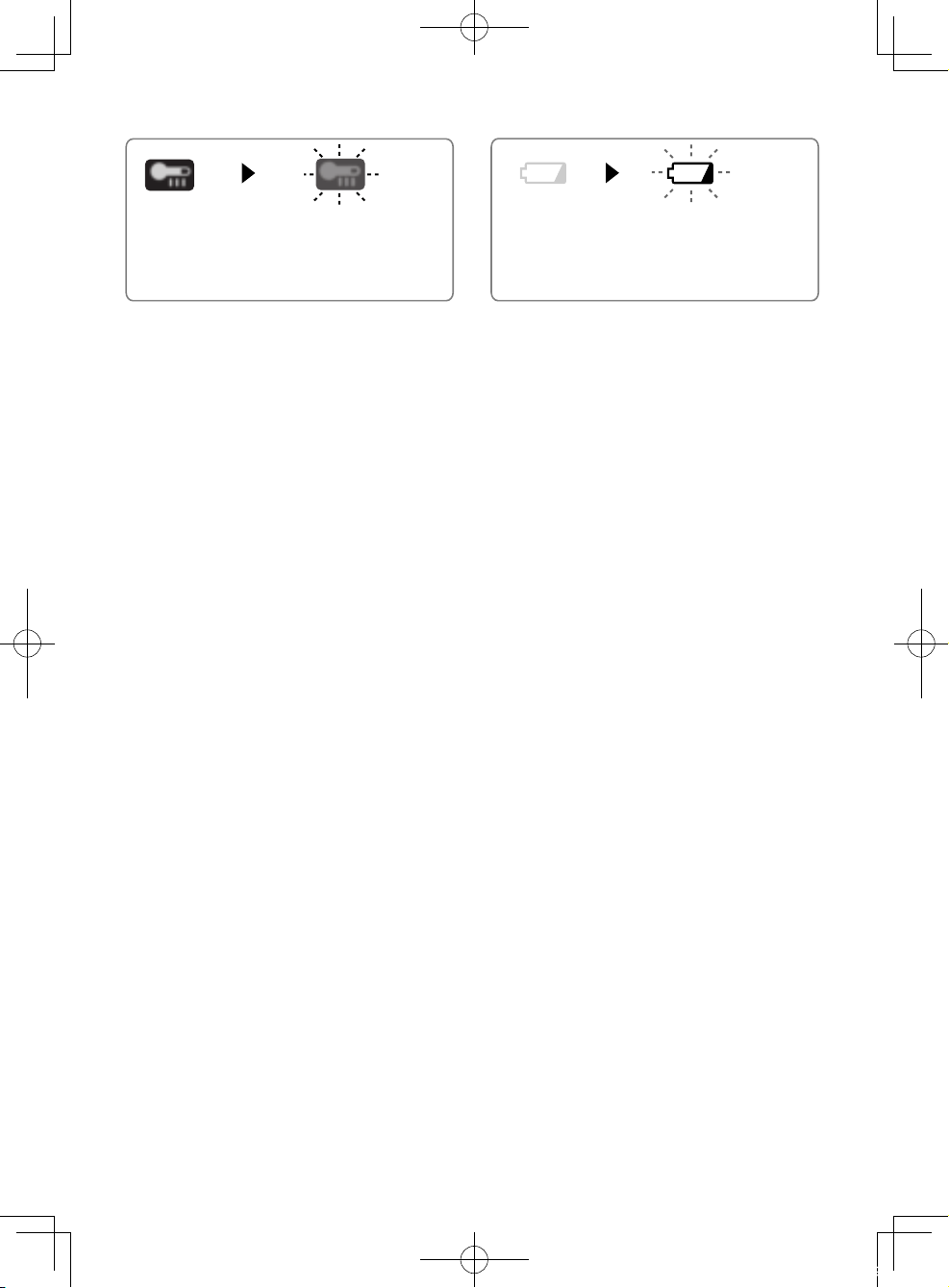
Überhitzungs-Warnlampe
Akkuladungs-Warnlampe
Aus
(normaler
Betrieb)
Blinken: Überhitzung
Zeigt an, dass der Betrieb
wegen Akku-Überhitzung
angehalten wurde.
Zum Schutz des Akkus müssen beim
Betrieb die folgenden Punkte beachtet
werden.
• Bei einer Akkuüberhitzung spricht die
Schutzschaltung an, um den Betrieb des
Motors oder des Akkus zu unterbrechen.
Die Überhitzungswarnleuchte auf dem
Bedienungsfeld leuchtet oder blinkt bei
aktivierter Funktion.
• Falls die Überhitzungs-Schutzfunktion
aktiviert wird, lassen Sie das Tool gründlich
abkühlen (mindestens 30 Minuten). Das
Tool ist wieder einsatzbereit, wenn die
Überhitzungs-Warnlampe erlischt.
• Verwenden Sie das Tool so, dass die
Überhitzungs-Schutzfunktion nicht
wiederholt aktiviert wird.
• Falls das Werkzeug kontinuierlich
unter starker Belastung oder bei
hoher Umgebungstemperatur im
Sommer verwendet wird, kann die
Überhitzungs-Schutzfunktion öfters
ansprechen.
• Falls das Werkzeug bei niedriger
Umgebungstemperatur im Winter oder
jeweils nur kurzzeitig verwendet wird,
spricht die Überhitzungs-Schutzfunktion
nicht an.
• Infolge der Arbeitsbedingungen und
anderer Faktoren nimmt die Leistung
des EY9L42 bei einer Temperatur von
10 °C und darunter stark ab.
• Der Umgebungstemperaturbereich liegt
zwischen 0°C und 40°C. Wenn der Akku
bei einer Akkutemperatur unter 0°C
benutzt wird, funktioniert die Maschine
möglicherweise nicht einwandfrei.
• Wenn ein kalter Akku (von etwa 0°C
oder weniger) in einem warmen
Raum aufgeladen werden soll,
lassen Sie den Akku für mindestens
eine Stunde in dem Raum und
laden Sie ihn auf, wenn er sich auf
Raumtemperatur erwärmt hat.
Aus
(normaler
Betrieb)
Blinken
(Keine Ladung)
Akkuschutzfunktion aktiv
Übermäßiges (vollständiges) Entladen von
Li-Ion-Akkus führt zu einer erheblichen
Verkürzung ihrer Lebensdauer. Das Tool ist
mit einer Akkuschutzfunktion ausgestattet,
die übermäßiges Entladen des Akkus
verhindert.
• Die Akkuschutzfunktion wird
unmittelbar vor der Erschöpfung des
Akkus aktiviert und bewirkt Blinken der
Akkuladungs-Warnlampe.
• Wenn Sie bemerken, dass die
Akkuladungs-Warnlampe blinkt, laden
Sie den Akku unverzüglich auf.
• Wird die Maschine bei zu geringer
Akku-Restladung gestartet, kann
sie stehen bleiben, ohne dass
zuvor die Akkuladungs-Warnlampe
blinkt. Dies zeigt an, dass zu wenig
Akku-Restladung für den Betrieb der
Maschine vorhanden ist. Daher sollte
der Akku vor weiterem Gebrauch
aufgeladen werden.
• Wird die Maschine während des Betriebs
einer plötzlichen Last ausgesetzt, die
Blockieren des Motors verursacht,
kann der Tiefentladungs-Schutzsensor
ausgelöst werden, so dass eventuell
die Akkuladungs-Warnlampe blinkt. Die
Lampe hört auf zu blinken, sobald die
Ursache der Motorblockierung behoben
und der Auslöser betätigt wird.
-
30 -
02GerEY46A2(EU).indd2110 2014/07/0212:02:19
 Loading...