

Page 1
Operating Instructions
Bedienungsanleitung
Instructions d’utilisation
Istruzioni per l’uso
Gebruiksaanwijzing
Manual de instrucciones
Brugsvejledning
Driftsföreskrifter
Bruksanvisning
Käyttöohjeet
Smerigliatrice angolare senza fili
Amoladora angular inalámbrica
Инструкция по эксплуатации
Iнструкцiя з експлуатації
Before operating this unit, please read these instructions completely and save this manual for future use.
Vor Inbetriebnahme des Gerätes die Betriebsanleitung bitte gründlich durchlesen und diese Broschüre zum späteren Nachschlagen
sorgfältig aufbewahren.
Lire entièrement les instructions suivantes avant de faire fonctionner l’appareil et conserver ce mode d’emploi à des fins de consultation
ultérieure.
Prima di usare questa unità, leggere completamente queste istruzioni e conservare il manuale per usi futuri.
Lees deze gebruiksaanwijzing aandachtig door voor u het apparaat in gebruik neemt en bewaar de gebruiksaanwijzing voor eventuele
naslag.
Antes de usar este aparato por primera vez, lea todas las instrucciones de este manual y guarde el manual para poderlo consultar en el
futuro.
Gennemlæs denne betjeningsvejledning før brugen og gem den til fremtidig brug.
Läs igenom hela bruksanvisningen innan verktyget tas i bruk. Spara bruksanvisningen för senare användning.
Før enheten tas i bruk, vennligst les disse alle anvisningene og oppbevar deretter bruksanvisningen for senere bruk.
Lue ohjeet huolella ennen laitteen käyttöönottoa ja säilytä tämä käyttöohje tallessa tulevaa tarvetta varten.
Перед эксплуатацией данного устройства, пожалуйста, полностью прочтите данную инструкцию и сохраните данное руководство
для использования в будущем..
Перед екплуатацiєю даного пристрою, будь ласка, повнiстю прочитайте дану iнструкцiю i збережiть даний посiбник для
використання у майбутньому.
Угловая шлифовальная машина с аккумуляторным питанием
Кутова шліфувальна машина з батарейним блоком
Model No: EY4640
Cordless Angle Grinder
Kabelloser Winkelschleifer
Meule d'angle sans fil
Snoerloze haakse slijper
Akku-vinkelslibemaskine
Sladdlös vinkelslipmaskin
Batteridrevet vinkelsliper
Ladattava kulmahiomakone
Page 2
Index/Index/Index/Indice/Index/Indice/Indeks/Index/Indeks/Hakemisto/
Индекс/Індекс
English: Page 6
Deutsch: Seite 23
Français: Page 39
Italiano: Pagina 55
Nederlands: Bladzijde 71
Español: Página 87
Dansk: Side 103
Svenska: Sid 118
Norsk: Side 133
Suomi: Sivu 148
Русский: Страница 163
Українська: Сторiнка 179
FUNCTIONAL DESCRIPTION
FUNKTIONSBESCHREIBUNG
DESCRIPTION DES FONCTIONS
DESCRIZIONE DELLE FUNZIONI
FUNCTIEBESCHRIJVING
DESCRIPCIÓN FUNCIONAL
FUNKTIONSBESKRIVELSE
FUNKTIONSBESKRIVNING
FUNKSJONSBESKRIVELSE
TOIMINTOKUVAUS
ФУНКЦИОНАЛЬНОЕ ОПИСАНИЕ
ФУНКЦIОНАЛЬНИЙ ОПИС
(D) (E) (F)
(C)
(B)
(A)
(G)
(Q)
(R)
(P)
(O)
(L)
(M)
(N)
(J)
- 2 -
(K)
(I)
(H)
(S)
Ni-MH
Ni-Cd
(T)
(U)
(V)
(W)
Page 3

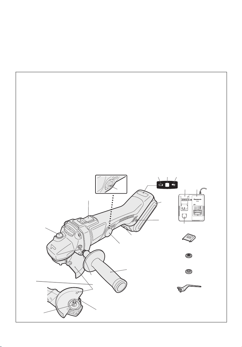
Power switch
Netzschalter
Interrupteur d’alimentation
Interruttore di accensione
Hoofdschakelaar
Interruptor de alimentación
(A)
Afbryder
Strömbrytare
Strømbryter
Käyttökytkin
Переключатель питания
Перемикач живлення
Display panel
Anzeigefeld
Ecran d'affichage
Display
Displaypaneel
Panel de exhibición
(C)
Displaypanel
Display
Displaypanel
Näyttöpaneeli
Индикаторная панель
Індикаторна панель
On lock warning lamp
Einschaltsicherungsleuchte
Témoin d'avertissement à verrou activé
Spia avvertenza blocco utensile
Waarschuwingslampje inschakelvergrendeling
Luz de advertencia de bloqueo
(E)
Låseadvarselslampe
Varningslampa för påslagningssäkring
Varsellampe for innkoblingssikring
Turvalukituksen merkkivalo
Предупреждающая лампа блокировки
Попереджувальна лампочка блокіровки
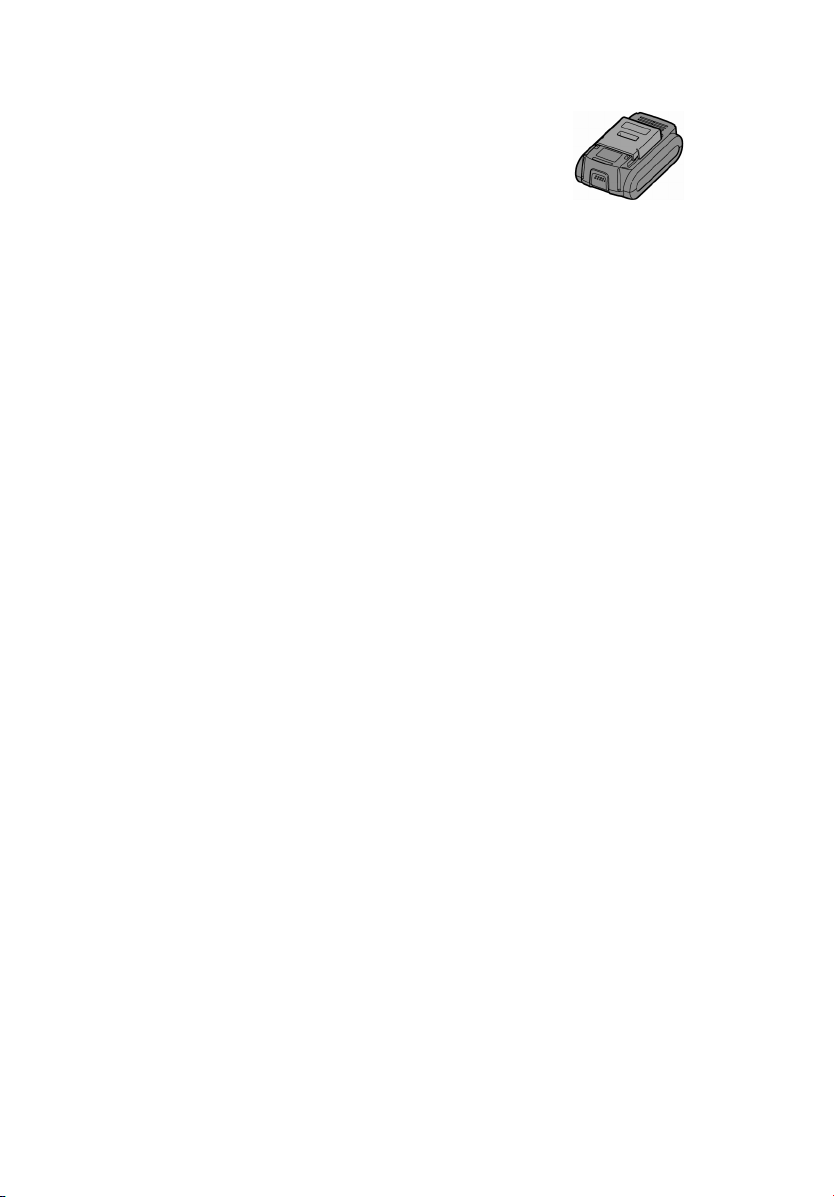
Battery pack (EY9L40/EY9L41)
Akku (EY9L40/EY9L41)
Batterie autonome (EY9L40/EY9L41)
Pacco batteria (EY9L40/EY9L41)
Accu (EY9L40/EY9L41)
Batería (EY9L40/EY9L41)
(G)
Batteripakning (EY9L40/EY9L41)
Batteri (EY9L40/EY9L41)
Batteripakke (EY9L40/EY9L41)
Akku (EY9L40/EY9L41)
Батарейный блок (EY9L40/EY9L41)
Батарейний блок (EY9L40/EY9L41)
Battery pack release button
Akku-Entriegelungsknopf
Bouton de libération de batterie autonome
Tasto di rilascio pacco batteria
Accu-ontgrendeltoets
Botón de liberación de batería
(I)
Udløserknap til batteripakning
Frigöringsknapp för batteri
Utløserknapp for batteripakke
Akkupaketin irrotuspainike
Кнопка освобождения батарейного блока
Кнопка вивільнення батарейного блоку
Brush cap
Bürstenkappe
Capuchon des charbons
Capsula spazzole
Borstelkap
Tapa de cepillo
(B)
Børstehætte
Borstlock
Børstehette
Harjan suojus
Колпачок щетки
Ковпачок щітки
Battery low warning lamp
Akkuladungs-Warnlampe
Témoin d’avertissement de batterie basse
Spia avvertenza batteria scarica
Waarschuwingslampje voor lage accuspanning
Luz de aviso de baja carga de batería
(D)
Advarselslampes batterieffekt lav
Varningslampa för svagt batteri
Varsellampe for at batteriet er for lavt
Alhaisen akkujännitteen varoituslamppu
Предупреждающая лампочка низкого заряда батареи
Попереджувальна лампочка низького заряду батареї
Overheat warning lamp (battery)
Überhitzungs-Warnlampe (Akku)
Témoin d’avertissement de surchauffe (batterie)
Spia avvertenza surriscaldamento (batteria)
Oververhitting-waarschuwingslampje (accu)
Luz de advertencia de sobrecalentamiento (batería)
(F)
Advarselslamp til overophedning (batteri)
Varningslampa för överhettning (batteri)
Varsellampe for overoppheting (batteri)
Ylikuumenemisen varoituslamppu (akku)
Предупреждающая лампочка перегрева (батареи)
Попереджувальна лампочка перегріву (батареї)
Alignment mark
Ausrichtmarkierung
Marque d'alignement
Marcatura di allineamento
Uitlijntekens
Marca de alineación
(H)
Flugtemærke
Anpassningsmärken
Innrettingsmerke
Sovitusmerkki
Метка совмещения
Мітка вирівнювання
Brush cap cover
Bürstenkappenabdeckung
Couvercle de capuchon des charbons
Copertura capsula spazzole
Borstelkapafdekking
Cubierta de tapa de cepillo
(J)
Børstehætteafdækning
Borstlockskydd
Børstehettedeksel
Hiiliharjan suojakansi
Заглушка колпачка щетки
Заглушка ковпачка щітки
- 3 -
Page 4

Support handle
Zusatzgriff
Manche de support
Maniglia di sostegno
Handgreep
Mango de soporte
(K)
Hjælpehåndtag
Stödhandtag
Støttehåndtak
Tukikahva
Поддерживающая рукоятка
Підтримуюча рукоятка
Grinding disc guard
Schleifscheibenschutz
Carter de disque abrasif
Carter disco mola
Afbraamschijfbeschermkap
Protección de disco de desbastado
(M)
Slibeskivebeskytter
Slipskivans skydd
Slipeskiveskjerm
Hiomalaikan suojus
Защитный кожух шлифовального круга
Захисний кожух шліфувального круга
Spindle
Spindel
Axe
Asse
As
Eje
(O)
Spindel
Spindel
Spindel
Kara
Шпиндель
Шпиндель
Li-ion battery pack dock
Li-Ion-Akkuladeschacht
Poste d’accueil de la batterie autonome Li-ion
Spazio raccordo pacco batteria Li-ion
Li-ion accuhouder
Enchufe de carga de batería Li-ión
(Q)
Li-ion batteripakningsdok
Docka för litiumjonbatteri
Dokk for Li-ion-batteripakke
Li-ioniakun liitin
Углубление для установки литий-ионного батарейного блока
Заглиблення для встановлення літій-іонного батарейного блоку
Support handle mounting hole
Montageloch für Stützgriff
Orifice de montage du manche de support
Foro montaggio maniglia di sostegno
Montage-opening van handgreep
Orificio de montaje de mango de soporte
(L)
Monteringshul til hjælpehåndtag
Monteringshål för stödhandtag
Monteringshull for støttehåndtak
Tukikahvan asennusaukko
Отверстие для крепления дополнительной рукоятки
Отвір для кріплення додаткової рукоятки
Grinding disc guard fixing screw
Schleifscheibenschutzschraube
Vis de fixation du carter de disque abrasif
Vite di fissaggio carter disco mola
Bevestigingsschroef van afbraamschijfbeschermkap
Tornillo de fijación de protector de disco de amoladora
(N)
Slibeskivebeskytter skrue
Låsskruv för slipskivans skydd
Festeskrue for slipeskiveskjerm
Hiontalaikan suojuksen kiinnitysruuvi
Скрепляющий винт кожуха шлифовального круга
Скріпляючий гвинт кожуха шліфувального круга
Spindle lock button
Spindelverriegelungstaste
Bouton de blocage de l'axe
Pulsante di blocco asse
Afbraamschijf
Botón de bloqueo de eje
(P)
Spindellåseknap
Spindelns låsknapp
Spindellåseknapp
Karan lukituspainike
Стопорная кнопка шпинделя
Стопорна кнопка шпінделя
Battery charger (EY0L80)
Ladegerät (EY0L80)
Chargeur de batterie (EY0L80)
Caricabatterie (EY0L80)
Acculader (EY0L80)
Cargador de batería (EY0L80)
(R)
Batterioplader (EY0L80)
Batteriladdare (EY0L80)
Batterilader (EY0L80)
Akkulaturi (EY0L80)
Зарядное устройство (EY0L80)
Зарядний пристрій (EY0L80)
- 4 -
Page 5

Ni-MH/Ni-Cd battery pack dock
Ni-MH/Ni-Cd-Akkuladeschacht
Poste d’accueil de la batterie autonome Ni-MH/Ni-Cd
Spazio raccordo pacco batteria Ni-MH/Ni-Cd
Ni-MH/Ni-Cd accuhouder
Enchufe de carga de batería Ni-MH/Ni-Cd
Ni-MH/Ni-Cd batteripakningsdok
(S)
Docka för NiMH/NiCd-batteri
Dokk for Ni-MH/Ni-Cd-batteripakke
Ni-MH/Ni-Cd akun latauspesä
Углубление для установки никель-металлогидридного
батарейного блока/никель-кадмиевого батарейного блока
Заглиблення для встановлення нікель-метал-гідридного
батарейного блоку/нікель-кадмієвого батарейного блоку
Clamp nut
Mutter
Écrou de serrage de collier
Dado di fissaggio
Klemmoer
Tuerca de abrazadera
(U)
Møtrik
Mutter
Klemmutter
Aluslevy
Фланцевая гайка
Фланцева гайка
Disc wrench
Scheibenschlüssel
Clé de disque
Chiave per il disco
Schijfsleutel
Llave de disco
(W)
Skivenøgle
Skivnyckel
Skivenøkkel
Lukituslaipan avain
Дисковый ключ
Дисковий ключ
Battery pack cover
Akkuabdeckung
Couvercle de la batterie autonome
Coperchio batterie
Accudeksel
Cubierta de la batería
Akkuafdækning
(T)
Batterilock
Batteripakkedeksel
Akun liitinsuoja
Крышка аккумуляторного блока
Кришка батарейного блоку
Disc flange
Scheibenflansch
Flasque du disque
Flangia disco
Schijfflens
Brida de disco
(V)
Skiveflange
Skivfläns
Skiveflens
Laikan lukituslaippa
Дисковый фланец
Дисковий фланець
- 5 -
Page 6
I. INTENDED USE
Thank you for purchasing the Panasonic
Angle Grinder. The powerful grinding
action of this tool, combined with the
convenience of its rechargeable battery
pack, provides you with great grinding
performance.
This Angle Grinder is only to be used for
grinding and cutting-off.
DANGER:
This product is a grinding tool, designed
to grind. It has a rotating disc which is
capable of cutting you deeply, causing
serious injury or death. As a result,
please read this manual and the cautionary markings on the tool carefully,
and obey all of the Safety Instructions to
avoid such injury.
WARNING:
To reduce the risk of injury, always
use proper guards when grinding.
How to Use This Manual
• Please read this manual completely
before starting to use your grinder. If
you let someone else use the grinder,
make sure they either read this manual or are fully instructed in the proper
use and all safety precautions concerning the grinder.
• Please keep this manual for future
reference. It contains important safety
information that you must follow to use
the grinder safely.
• This manual and product use the following signal words:
NOTE:
Notes provide additional information
that you should know about the grinder.
CAUTION:
Caution indicates a potentially hazardous situation, which could result in
minor or moderate injury if not avoided.
Cautions also alert you to unsafe practices to be avoided.
WARNING:
Warning indicates a potentially hazardous situation, which could result in
serious injury or death if not avoided.
DANGER:
Danger indicates an imminent hazard
which will result in serious injury or
death if not avoided.
Read the “Safety Instructions” booklet
and the following before using.
II. ADDITIONAL
SAFETY RULES
Safety instructions for all operations
Safety warning common for Grinding
or Abrasive Cutting-off operations:
1)
This power tool is intended to
function as a grinder, or cut-off
tool. Read all safety warnings,
instructions, illustrations and
specifications provided with this
power tool.
structions listed below may result in
electric shock, fire and/or serious
injury.
2)
Operations such as sanding,
wire brushing, polishing are not
recommended to be performed
with this power tool.
for which the power tool was not
designed may create a hazard and
cause personal injury.
3)
Do not use accessories which
are not specifically designed and
recommended by the tool
manufacturer.
accessory can be attached to your
power tool, it does not assure safe
operation.
4)
The rated speed of the accessory
must be at least equal to the
maximum speed marked on the
power tool.
faster than their RATED SPEED
can break and fly apart.
Failure to follow all in-
Operations
Just because the
Accessories running
- 6 -
Page 7

5)
The outside diameter and the
thickness of your accessory must
be within the capacity rating of
your power tool.
accessories cannot be adequately
guarded or controlled.
6)
The arbour size of wheels, flanges,
backing pads or any other accessory must properly fit the
spindle of the power tool.
sories with arbour holes that do not
match the mounting hardware of
the power tool will run out of balance, vibrate excessively and may
cause loss of control.
7)
Do not use a damaged accessory.
Before each use inspect the accessory such as abrasive wheels
for chips and cracks. If power tool
or accessory is dropped, inspect
for damage or install an undamaged accessory. After inspecting
and installing an accessory, position yourself and bystanders
away from the plane of the rotating accessory and run the power
tool at maximum no-load speed
for one minute.
sories will normally break apart during this test time.
8)
Wear personal protective
equipment. Depending on application, use face shield, safety
goggles or safety glasses. As
appropriate, wear dust mask,
hearing protectors, gloves and
workshop apron capable of
stopping small abrasive or
workpiece fragments. The eye
protection must be capable of
stopping flying debris generated
by various operations.
protection must be capable of
stopping flying debris generated by
various operations. The dust mask
or respirator must be capable of filtrating particles generated by your
operation. Prolonged exposure to
high intensity noise may cause
hearing loss.
Incorrectly sized
Acces-
Damaged acces-
The eye
9)
Keep bystanders a safe distance
away from work area. Anyone
entering the work area must wear
personal protective equipment.
Fragments of workpiece or of a
broken accessory may fly away and
cause injury beyond immediate area
of operation.
10)
Hold power tool by insulated gripping surfaces only, when performing an operation where the cutting
accessory may contact hidden wiring or its own cord.
sory contacting a “live” wire may
make exposed metal parts of the
power tool “live” and shock the operator.
11)
Position the cord clear of the
spinning accessory.
control, the cord may be cut or
snagged and your hand or arm may
be pulled into the spinning accessory.
12)
Never lay the power tool down
until the accessory has come to a
complete stop.
cessory may grab the surface and
pull the power tool out of your control.
13)
Do not run the power tool while
carrying it at your side.
contact with the spinning accessory
could snag your clothing, pulling the
accessory into your body.
14)
Regularly clean the power tool’s
air vents.
the dust inside the housing and
excessive accumulation of powdered metal may cause electrical
hazards.
15)
Do not operate the power tool near
flammable materials.
ignite these materials.
16)
Do not use accessories that require liquid coolants.
or other liquid coolants may result in
electrocution or shock.
The motor’s fan will draw
Cutting acces-
If you lose
The spinning ac-
Accidental
Sparks could
Using water
- 7 -
Page 8

Further safety instructions for
all operations
Kickback and Related Warnings
Kickback is a sudden reaction to a
pinched or snagged rotating wheel,
backing pad, brush or any other accessory. Pinching or snagging causes rapid
stalling of the rotating accessory which
in turn causes the uncontrolled power
tool to be forced in the direction opposite
of the accessory’s rotation at the point of
the binding.
For example, if an abrasive wheel is
snagged or pinched by the workpiece,
the edge of the wheel that is entering
into the pinch point can dig into the
surface of the material causing the
wheel to climb out or kick out. The
wheel may either jump toward or away
from the operator, depending on direction of the wheel’s movement at the
point of pinching. Abrasive wheels may
also break under these conditions.
Kickback is the result of power tool
misuse and/or incorrect operating
procedures or conditions and can be
avoided by taking proper precautions
as given below.
1)
Maintain a firm grip on the power
tool and position your body and
arm to allow you to resist kickback
forces. Always use auxiliary handle,
if provided, for maximum control
over kickback or torque reaction
during start-up.
control torque reactions or kickback
forces, if proper precautions are
taken.
2)
Never place your hand near the
rotating accessory.
kickback over your hand.
3)
Do not position your body in the
area where power tool will move
if kickback occurs.
propel the tool in direction opposite
to the wheel’s movement at the
point of snagging.
4)
Use special care when working
corners, sharp edges etc. Avoid
bouncing and snagging the accessory.
The operator can
Accessory may
Kickback will
Corners, sharp edges or
bouncing have a tendency to snag
the rotating accessory and cause
loss of control or kickback.
5)
Do not attach a saw chain woodcarving blade or toothed saw
Such blades create frequent
blade.
kickback and loss of control.
Additional safety instructions for
grinding and cutting-off operations
Safety warnings specific for Grinding
and Abrasive Cutting-off operations:
1)
Use only wheel types that are
recommended for your power
tool and the specific guard designed for the selected wheel.
Wheels for which the power tool
was not designed cannot be adequately guarded and are unsafe.
2)
The guard must be securely attached to the power tool and positioned for maximum safety, so
the least amount of wheel is exposed towards the operator.
guard helps to protect operator
from broken wheel fragments and
accidental contact with wheel.
3)
Wheels must be used only for recommended applications. For exam-
- 8 -
ple: do not grind with the side of
cut-off wheel.
are intended for peripheral grinding,
side forces applied to these wheels
may cause them to shatter.
4)
Always use undamaged wheel
flanges that are of correct size and
shape for your selected wheel.
Proper wheel flanges support the
wheel thus reducing the possibility of
wheel breakage. Flanges for cut-off
wheels may be different from grinding wheel flanges.
5)
Do not use worn down wheels
from larger power tools.
intended for larger power tool is not
suitable for the higher speed of a
smaller tool and may burst.
Abrasive cut-off wheels
The
Wheel
Page 9
Additional Safety Warnings Specific for Abrasive Cutting-Off Operations:
1)
Do not “jam” the cut-off wheel or
apply excessive pressure. Do
not attempt to make an excessive depth of cut.
the wheel increases the loading
and susceptibility to twisting or
binding of the wheel in the cut and
the possibility of kickback or wheel
breakage.
2)
Do not position your body in line
with and behind the rotating
wheel.
When the wheel, at the point
of operation, is moving away from
your body, the possible kickback
may propel the spinning wheel and
the power tool directly at you.
3)
When wheel is binding or when
interrupting a cut for any reason,
switch off the power tool and
hold the power tool motionless
until the wheel comes to a complete stop. Never attempt to remove the cut-off wheel from the
cut while the wheel is in motion
otherwise kickback may occur.
Investigate and take corrective action to eliminate the cause of wheel
binding.
4)
Do not restart the cutting operation in the workpiece. Let the
wheel reach full speed and carefully reenter the cut.
may bind, walk up or kickback if the
power tool is restarted in the workpiece.
5)
Support panels or any oversized
workpiece to minimize the risk of
wheel pinching and kickback.
Large workpieces tend to sag under
their own weight. Supports must be
placed under the workpiece near the
line of cut and near the edge of the
workpiece on both sides of the
wheel.
Overstressing
The wheel
6)
Use extra caution when making a
“pocket cut” into existing walls or
other blind areas.
The protruding
wheel may cut gas or water pipes,
electrical wiring or objects that can
cause kickback.
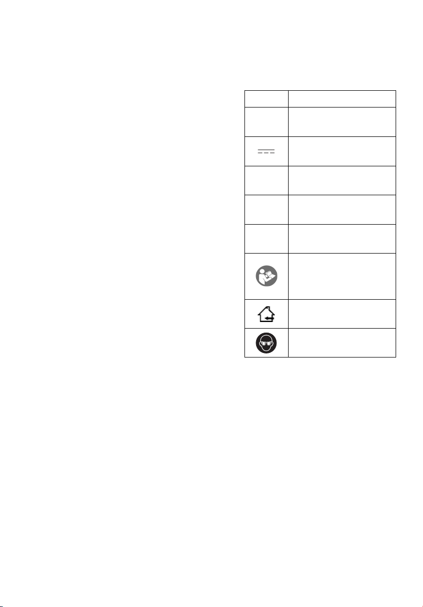
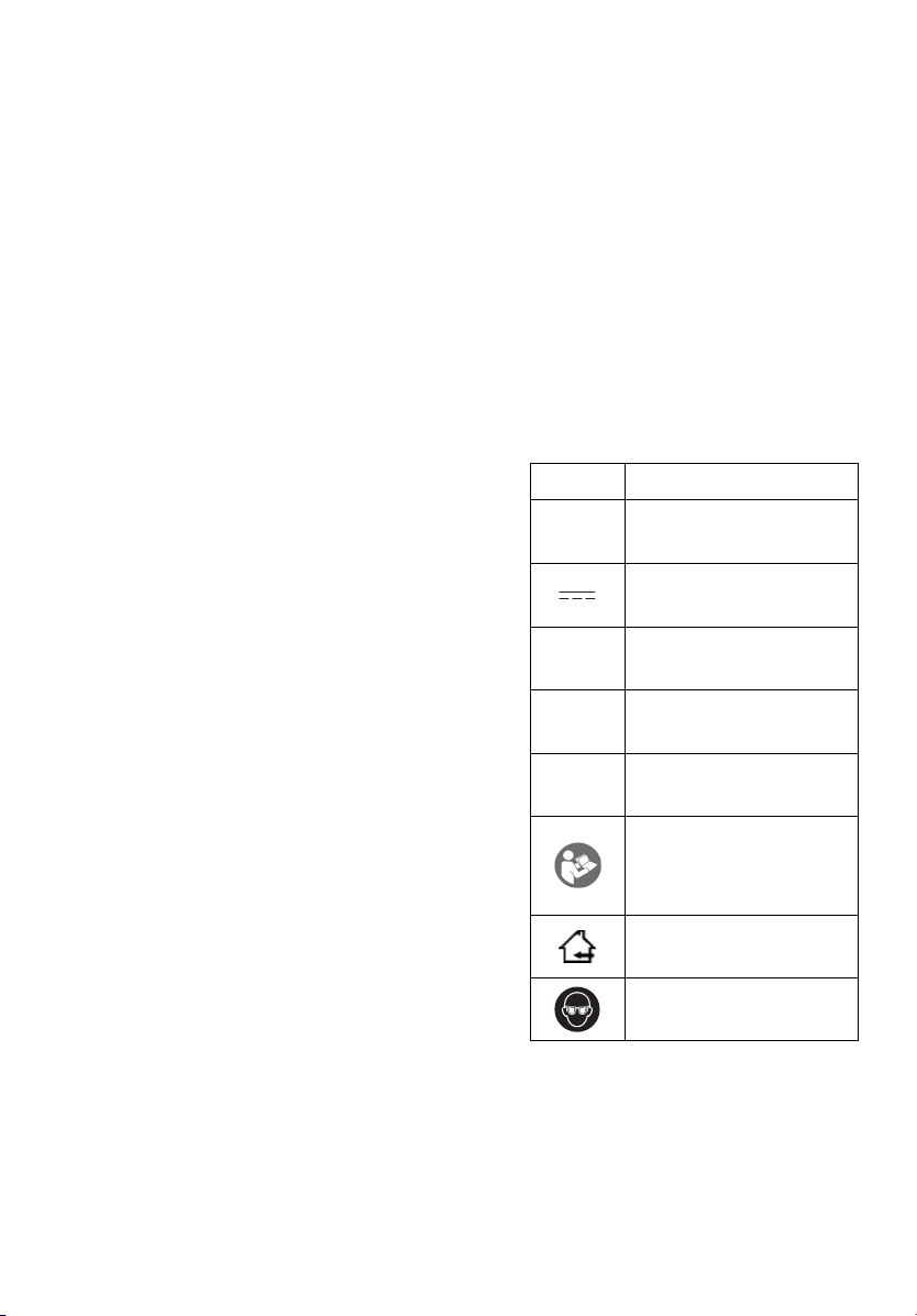
Symbol Meaning
V Volts
n
-1
…min
Ah
For indoor use only.
Direct current
Rated speed
Revolutions or reciproca-
tions per minutes
Electrical capacity of
battery pack
To reduce the risk of
injury, user must read
and understand instruc-
tion manual.
Always wear eye protec-
tion
- 9 -
Page 10
III. ASSEMBLY
NOTE:
When attaching or removing a slide
handle, disconnect battery pack from
tool.
CAUTION:
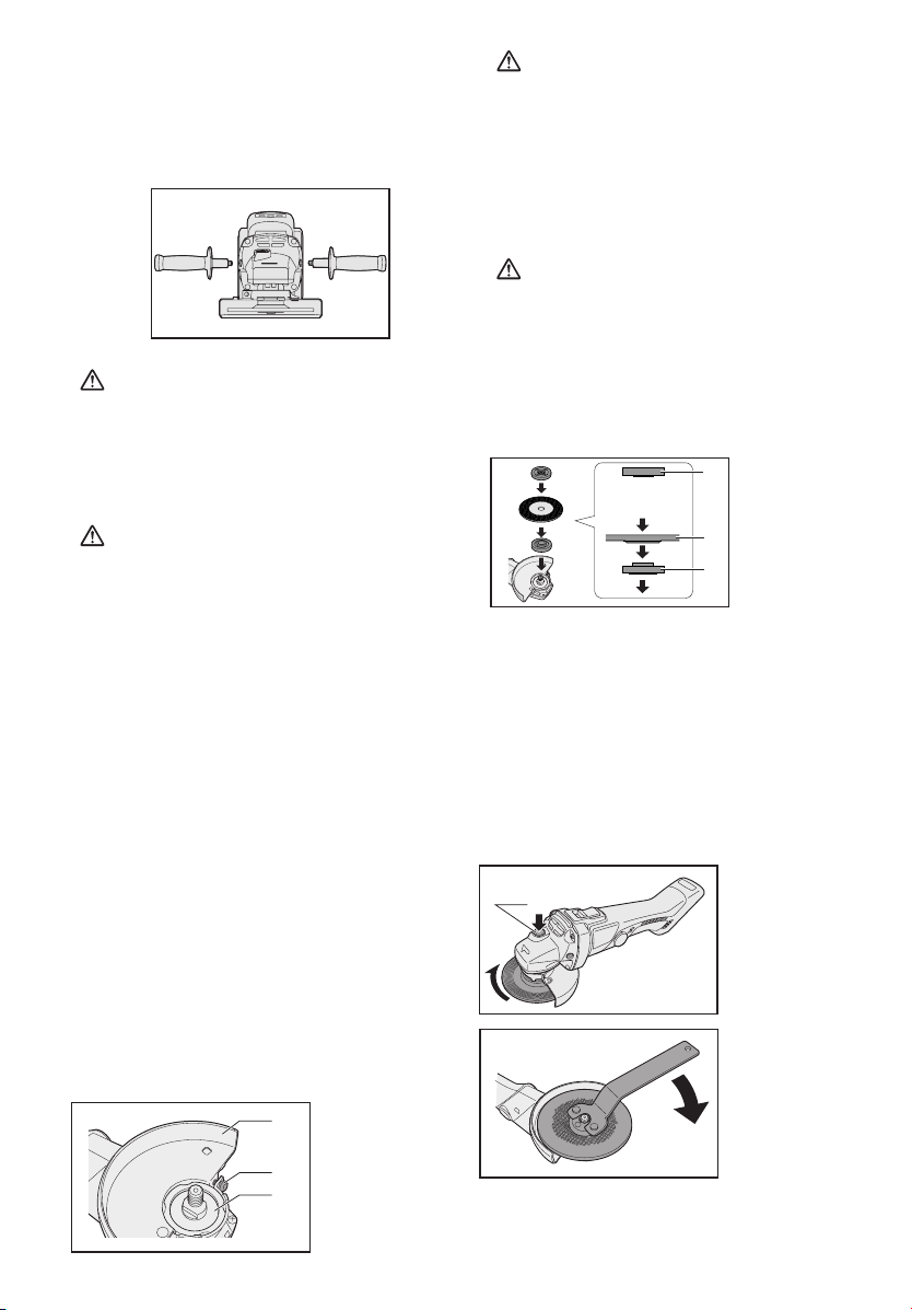
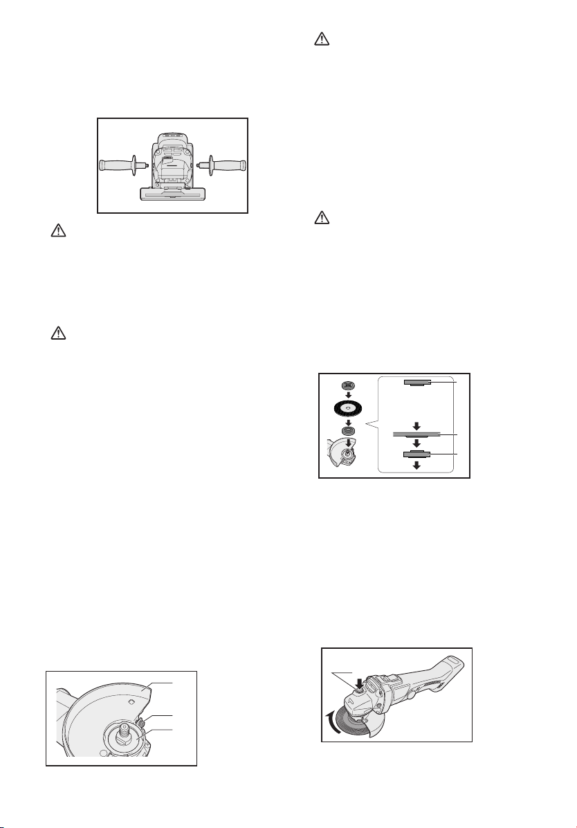
• Always be sure that the side handle
is installed securely before operation.
Screw the side handle securely as
shown in the figure.
CAUTION:
• Never actuate the lock pin when the
spindle is rotating. The tool may be
damaged.
Press the lock button to prevent spindle
rotation when installing or removing
parts, such as grinding disc, disc guard,
etc.
Installing or removing disc
Inspection before use
• Has the correct grinding disc
been mounted for the object to be
ground?
• Has the proper diameter of the
grinding disc been mounted for
the tool rating?
• Has the proper grinding disc
compiled to safety standard listed
below been mounted?
Europe – EN, Australia - AS
1
3
2
1. Grinding disc
guard
2. Spindle
3. Grinding disc
guard fixing
screw
CAUTION:
• When using, the Grinding disc guard
must be installed on the tool so that
the closed side of the guard always
faces toward the operator.
• Ensure that blotters are used when
they are provided with the bonded
abrasive product and when they are
required;
WARNING:
• Always use supplied guard when
using tool. Grinding disc can shatter
during use and Grinding disc guard
helps to reduce chances of personal
injury.
1. Install the Grinding disc guard, and
then securely tighten the screw.
1. Clamp nut
Make sure
the side.
1
2
3
2. Grinding disc
3. Disc flange
2. Install the disc flange and the disc
to the spindle in order as shown in
the figure.
3. Tighten the clamp nut onto the
spindle so that hollow side faces
opposite direction to the disc.
4. Push the Spindle lock button to
secure the spindle in place, and
then use the clamp nut wrench to
tighten the clamp nut securely.
1. Spindle lock
1
button
5. To remove the grinding disc, follow
the installation procedure in reverse.
- 10 -
Page 11
A
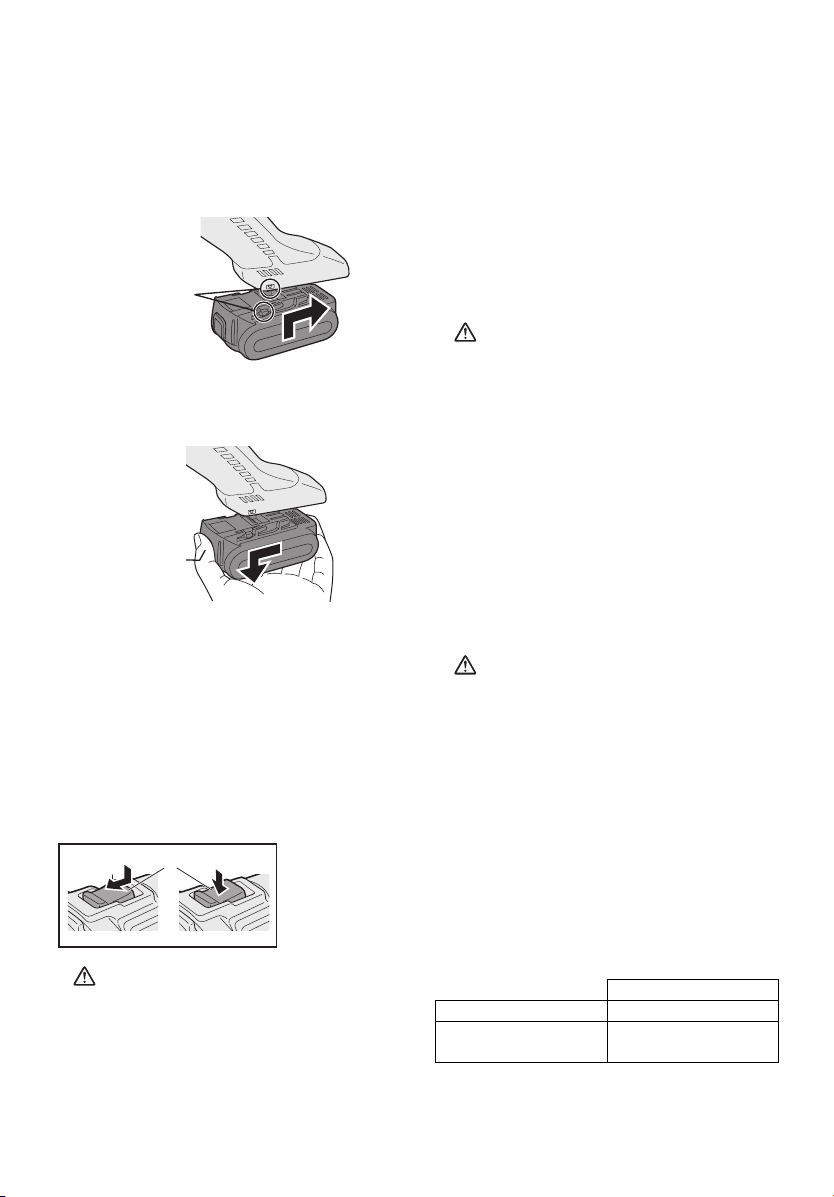
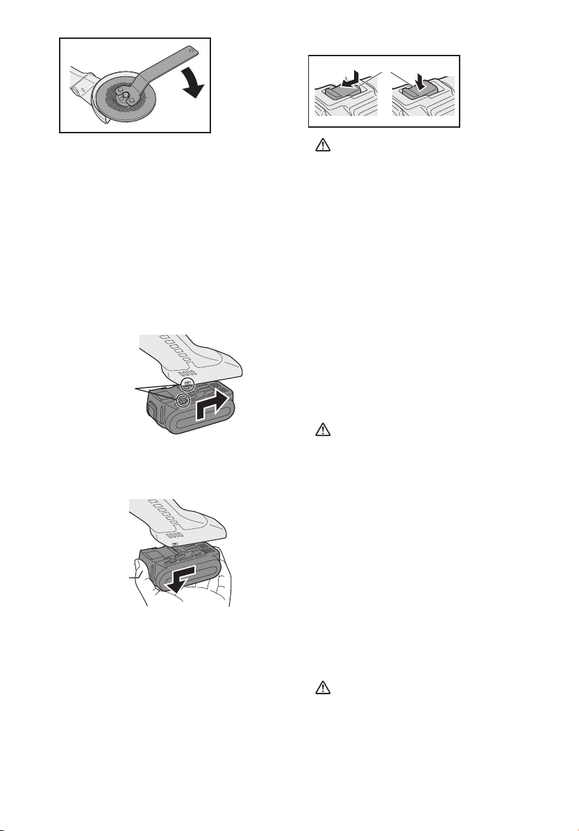
Attaching or Removing Battery
Pack
1. To connect the battery pack:
Line up the alignment marks and attach the battery pack.
• Slide the battery pack until it locks
into position.
lignment marks
2. To remove the battery pack:
Push on the button from the front to
release the battery pack.
Button
• Power switch can be locked in “ON”
position. Stay alert when locking
tool in “ON” position and grasp the
tool firmly using support handle and
grip.
To start the tool, press and slide the
power switch toward the “ON” position.
For continuous operation, press the
front of the power switch to lock it.
To stop the tool, press the rear of the
power switch, then slide it toward the
“OFF” position.
WARNING:
• It should never be necessary to
force the tool. The weight of the
tool applies adequate pressure.
Forcing and excessive pressure
could cause dangerous grinding
disc breakage.
• ALWAYS replace grinding disc if
tool is dropped while grinding.
• NEVER bang or hit grinding disc.
• Avoid bouncing and snagging the
grinding disc, especially when working corners, sharp edges etc. This
can cause loss of control and kickback.
IV. OPERATION
NOTE:
Be aware that this tool is always in
an operating condition, since it
does not have to be plugged into
an electrical outlet.
Power switch operation
1
CAUTION:
• Before inserting the battery pack
into the tool, always make sure that
the power switch operates properly
and returns to the “OFF” position
when the rear of the power switch
is depressed.
1. Power switch
CAUTION:
• After operation, always switch off
the tool and wait until the wheel has
come to a complete stop before
putting the tool down.
Visual inspection and workout
test on disc
1. Always make sure that the disc has
no cracks before use.
2. Always give workout test on the
blade as follows.
3. Always make sure the disc is firmly
fixed.
Brand new disc more than 3 min.
Before use on
current disc
- 11 -
Work out time
more than 1 min.
Page 12
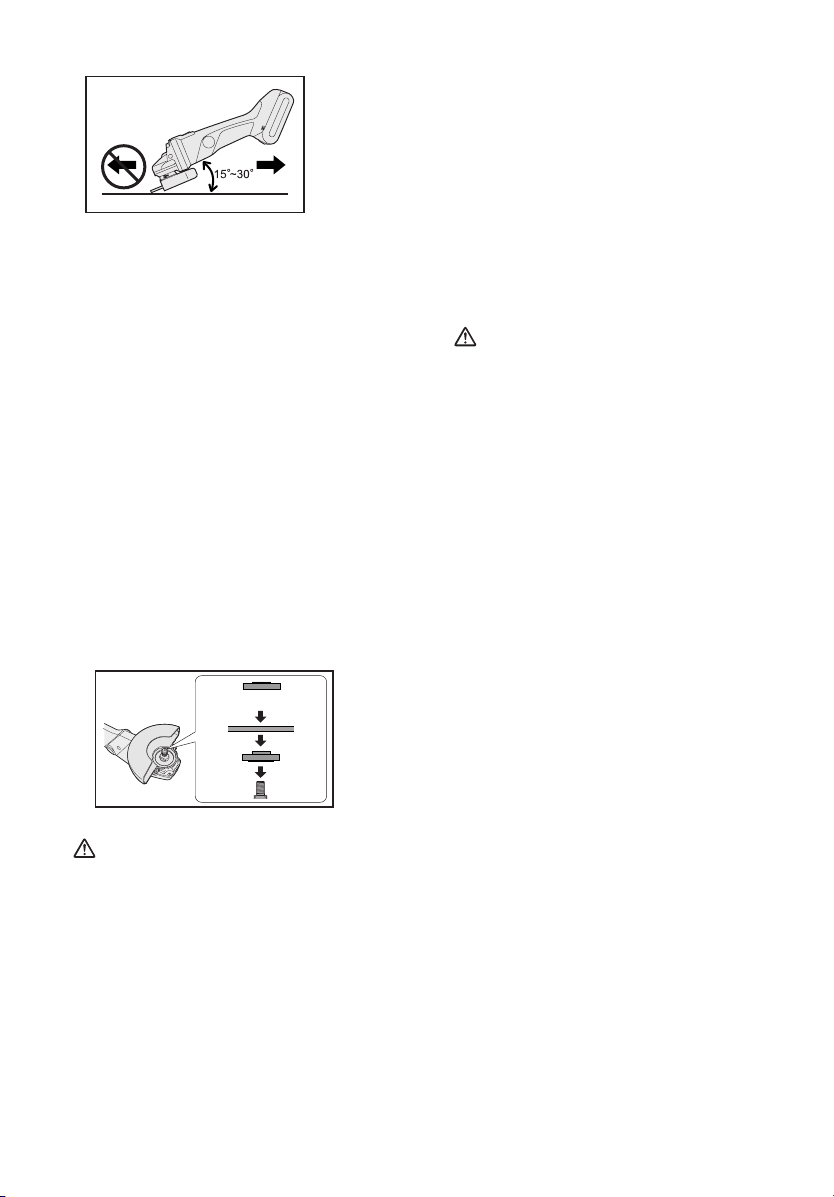
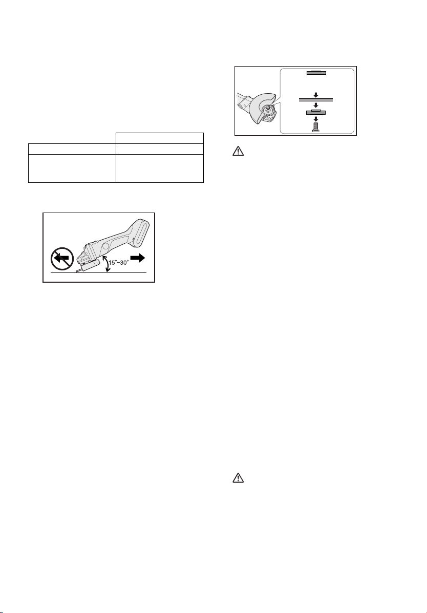
Grinding operation
AB
ALWAYS hold the tool firmly with one
hand on grip and the other on the side
handle. Turn on the tool on and then
apply the wheel or disc to the workpiece.
In general, keep the edge of the
wheel or grinding disc at an angle of
about 15 degrees to the workpiece
surface.
When using a new grinding disc, do
not work the grinder in the B direction
or it will cut into the workpiece. Once
the edge of the grinding disc has been
rounded off by use, the grinding disc
may be worked in both A and B direction.
Using a cut-off disc guard
(EY9X213E) (Available as an
accessory, not included)
Make sure the side.
breakage and overheating of the
motor may occur.
• Do not start when disc is in the
workpiece. To do so causes the
cut-off disc binding or kickback. Let
the cut-off disc reach full speed and
then carefully cut the workpiece.
• During cutting operations, never
change the angle of the disc. Placing side pressure on the cut-off
disc (as in grinding) will cause the
disc to crack and break, causing
serious personal injury.
CAUTION:
• To prevent excessive temperature
increase of the tool surface, do not
operate the tool continuously using two or more battery packs. The
tool needs cool-off time before
switching to another pack.
• Do not close up ventilation slots on
the sides of the body during operation. Otherwise, the machine function is adversely affected to cause a
failure.
• Do NOT strain the tool (motor). This
may cause damage to the unit.
• Use the tool in such a way as to
prevent the air from the ventilation
slots from blowing directly onto
your skin. Otherwise, you may get
burned.
WARNING:
• When using an abrasive cut-off
disc, be sure to use only the cut-off
disc guard designed for this use
with cut-off disc.
• NEVER use cut-off disc for grinding.
• Do not jam the Disc or apply excessive pressure. Do not attempt
to make an excessive depth of cut.
Overstressing the cut-off disc increases the loading and susceptibility to twisting or binding of the
cut-off disc in the cut and the possibility of kickback, cut-off disc
- 12 -
Page 13
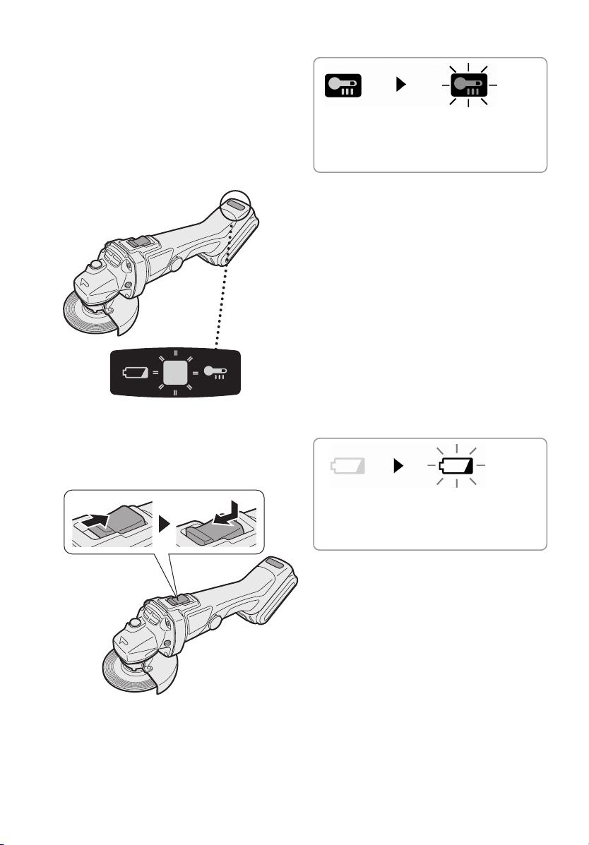
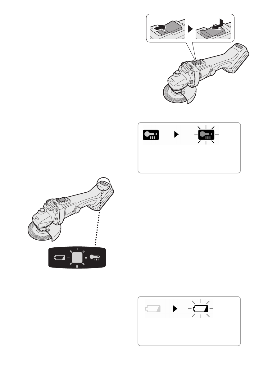
g
Indicator lamp for On lock
warning lamp function
The grinder will not start when the
switch is at the ON position (switch
lever at ON), even when the battery
pack is inserted. The warning lamp
will flash at this time to indicate that
the on lock start prevention function
has operated.
Press the switch to the OFF position
(switch lever at OFF) and then press
it back to the ON position (switch
lever at ON) to start the grinder.
ON OFF
Overheat warning lamp
Off
(normal
operation)
The overheating protection feature
halts operation to protect the battery
pack in the event of overheating. The
overheat warning lamp on the control
panel flashes when this feature is active.
• If the overheating protection feature
activates, allow the tool to cool thoroughly (at least 30 minutes). The
battery is ready for use when the
overheat warning lamp goes out.
• Avoid using the tool in a way that
causes the overheating protection
feature to activate repeatedly.
Flashing: Overheat
Indicates operation has
been halted due to battery
overheatin
.
Battery low warning lamp
Off
(normal
operation)
Excessive (complete) discharging of
lithium ion batteries shortens their service life dramatically. The tool includes
a battery protection feature designed to
prevent excessiv
battery pack.
• The battery protection feature activates immediately before the battery
loses its charge, causing the battery
low warning lamp to flash.
• If you notice the battery low warning
lamp flashing, charge the battery
pack immediately.
Flashing
(No charge)
Battery protection
feature active
e discharging of the
- 13 -
Page 14
- Accidental re-start preventive function
- Even if the battery pack is inserted
on the tool with the power switch in
the “ON” position, the tool does not
start. At this time, the lamp flickers
slowly and this shows that the
accidental re-start preventive
function is at work.
- To start the tool, first slide the power
switch toward the “OFF” position
and then slide it toward the “ON”
position.
[Battery Pack]
For Appropriate Use of
Battery pack
Li-ion Battery pack (EY9L40/EY9L41)
• For optimum battery life, store the
Li-ion battery pack following use
without charging it.
• When charging the battery pack,
confirm that the terminals on the
battery charger are free of foreign
substances such as dust and water etc.
Clean the terminals before charging
the battery pack if any foreign
substances are found on the terminals.
The life of the battery pack terminals
may be affected by foreign
substances such as dust and water
etc. during operation.
• When battery pack is not in use,
keep it away from other metal
objects like: paper clips, coins, keys,
nails, screws, or other small metal
objects that can make a connection
from one terminal to another.
Shorting the battery terminals
together may cause sparks, burns or
a fire.
• When operating the battery pack,
make sure the work place is well
ventilated.
• When the battery pack is removed
from the main body of the tool, replace the battery pack cover immediately in order to prevent dust or dirt
from contaminating the battery terminals and causing a short circuit.
Battery Pack Life
The rechargeable batteries have a
limited life. If the operation time
becomes extremely short after
recharging, replace the battery pack
with a new one.
Battery Recycling
ATTENTION:
For environmental protection and
recycling of materials, be sure that
it is disposed of at an officially
assigned location, if there is one in
your country.
[Battery Charger]
Charging
Cautions for the Li-ion Battery
Pack
• If the temperature of the battery pack
falls approximately below −10°C
(14°F), charging will automatically
stop to prevent degradation of the
battery.
Common Cautions for the
Li-ion/Ni-MH/Ni-Cd Battery Pack
• The ambient temperature range is
between 0°C (32°F) and 40°C (104°F).
If the battery pack is used when the
battery temperature is below 0°C (32°F),
the tool may fail to function properly.
• When charging a cool battery pack
(below 0°C (32°F)) in a warm place,
leave the battery pack at the place and
wait for more than one hour to warm
up the battery to the level of the am-
- 14 -
Page 15
A
bient temperature.
• Cool down the charger when charging
more than two battery packs consecutively.
• During charging, the charger may
become slightly warm. This is normal.
Do NOT charge the battery for a long
period.
CAUTION:
To prevent the risk of fire or damage
to the battery charger.
• Do not use power source from an
engine generator.
• Do not cover vent holes on the
charger and the battery pack.
• Unplug the charger when not in use.
Li-ion Battery Pack
NOTE:
Your battery pack is not fully
charged at the time of purchase.
Be sure to charge the battery before use.
Battery charger (EY0L80)
1. Plug the charger into the AC outlet.
NOTE:
Sparks may be produced when the
plug is inserted into the AC power
supply, but this is not a problem in
terms of safety.
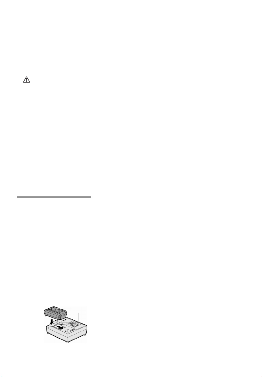
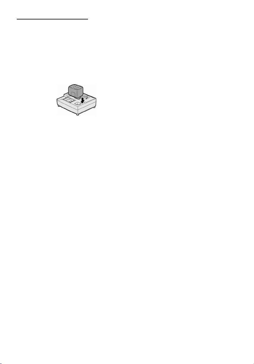
2. Insert the battery pack firmly into
the charger.
1. Line up the alignment marks and
place the battery onto the dock on
the charger.
2. Slide forward in the direction of the
arrow.
lignment marks
3. During charging, the charging lamp
will be lit.
When charging is completed, an
internal electronic switch will
automatically be triggered to prevent overcharging.
• Charging will not start if the battery
pack is warm (for example, immediately after heavy-duty operation).
The orange standby lamp will be
flashing until the battery cools down.
Charging will then begin automati-
cally.
4. The charge lamp (green) will flash
slowly once the battery is approximately 80% charged.
5. When charging is completed, the
charging lamp will start flashing
quickly in green color.
6. If the temperature of the battery pack
is 0°C or less, charging takes longer
to fully charge the battery pack than
the standard charging time.
Even when the battery is fully charged,
it will have approximately 50% of the
power of a fully charged battery at
normal operating temperature.
7. If the power lamp does not light immediately after the charger is plugged
in, or if after the standard charging
time the charging lamp does not flash
quickly in green, consult an authorized service center.
8. If a fully charged battery pack is inserted into the charger again, the
charging lamp lights up. After several minutes, the charging lamp may
flash quickly to indicate the charging
is completed.
Ni-MH/Ni-Cd Battery Pack
NOTE:
When you charge the battery pack
for the first time, or after prolonged
storage, charge it for about 24
hours to bring the battery up to full
capacity.
- 15 -
Page 16
Battery charger (EY0L80)
1. Plug the charger into the AC outlet.
NOTE:
Sparks may be produced when the
plug is inserted into the AC power
supply, but this is not a problem in
terms of safety.
2. Insert the battery pack firmly into
the charger.
3. During charging, the charging lamp
will be lit.
When charging is completed, an internal electronic switch will automatically be triggered to prevent
overcharging.
• Charging will not start if the battery
pack is warm (for example, immediately after heavy-duty operation).
The orange standby lamp will be
flashing until the battery cools down.
Charging will then begin automatically.
4. When charging is completed, the
charging lamp will start flashing
quickly in green color.
5. If the charging lamp does not light
immediately after the charger is
plugged in, or if after the standard
charging time the charging lamp does
not flash quickly in green, consult an
authorized service center.
6. If a fully charged battery pack is inserted into the charger again, the
charging lamp lights up. After several minutes, the charging lamp may
flash quickly to indicate the charging
is completed.
- 16 -
Page 17
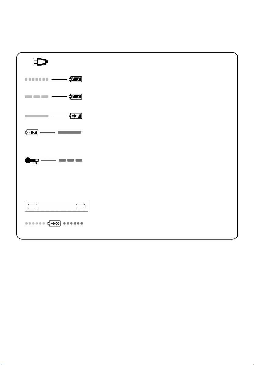
LAMP INDICATIONS
Green Lit
Charger is plugged into the AC outlet.
Ready to charge.
Green Flashing Quickly
Charging is completed. (Full charge.)
Green Flashing
Battery is approximately 80% charged. (Usable charge.
Li-ion only.)
Green Lit
Now charging.
Orange Lit
Battery pack is cool.
The battery pack is being charged slowly to reduce the load
on the battery. (Li-ion only.)
Orange Flashing
Battery pack is warm. Charging will begin when temperature
of battery pack drops.
If the temperature of the battery pack is –10°C or less, the
charging status lamp (orange) will also start flashing.
Charging will begin when the temperature of the battery
pack goes up (Li-ion only).
Charging Status Lamp
Left: green Right: orange will be displayed.
Both Orange and Green Flashing Quickly
Charging is not possible. Clogged with dust or malfunction of
the battery pack.
- 17 -
Page 18
Information for Users on Collection and Disposal of Old
Equipment and used Batteries
These symbols on the products, packaging, and/or accompanying
documents mean that used electrical and electronic products and
batteries should not be mixed with general household waste.
For proper treatment, recovery and recycling of old products and used
batteries, please take them to applicable collection points, in accordance
with your national legislation and the Directives 2002/96/EC and
2006/66/EC.
By disposing of these products and batteries correctly, you will help to
save valuable resources and prevent any potential negative effects on
human health and the environment which could otherwise arise from
inappropriate waste handling.
For more information about collection and recycling of old products and
batteries, please contact your local municipality, your waste disposal
service or the point of sale where you purchased the items.
Penalties may be applicable for incorrect disposal of this waste, in
accordance with national legislation.
For business users in the European Union
If you wish to discard electrical and electronic equipment, please contact your
dealer or supplier for further information.
[Information on Disposal in other Countries outside the European Union]
These symbols are only valid in the European Union. If you wish to discard these
items, please contact your local authorities or dealer and ask for the correct method
of disposal.
Note for the battery symbol (bottom two symbol examples):
This symbol might be used in combination with a chemical symbol. In this case it
complies with the requirement set by the Directive for the chemical involved.
- 18 -
Page 19
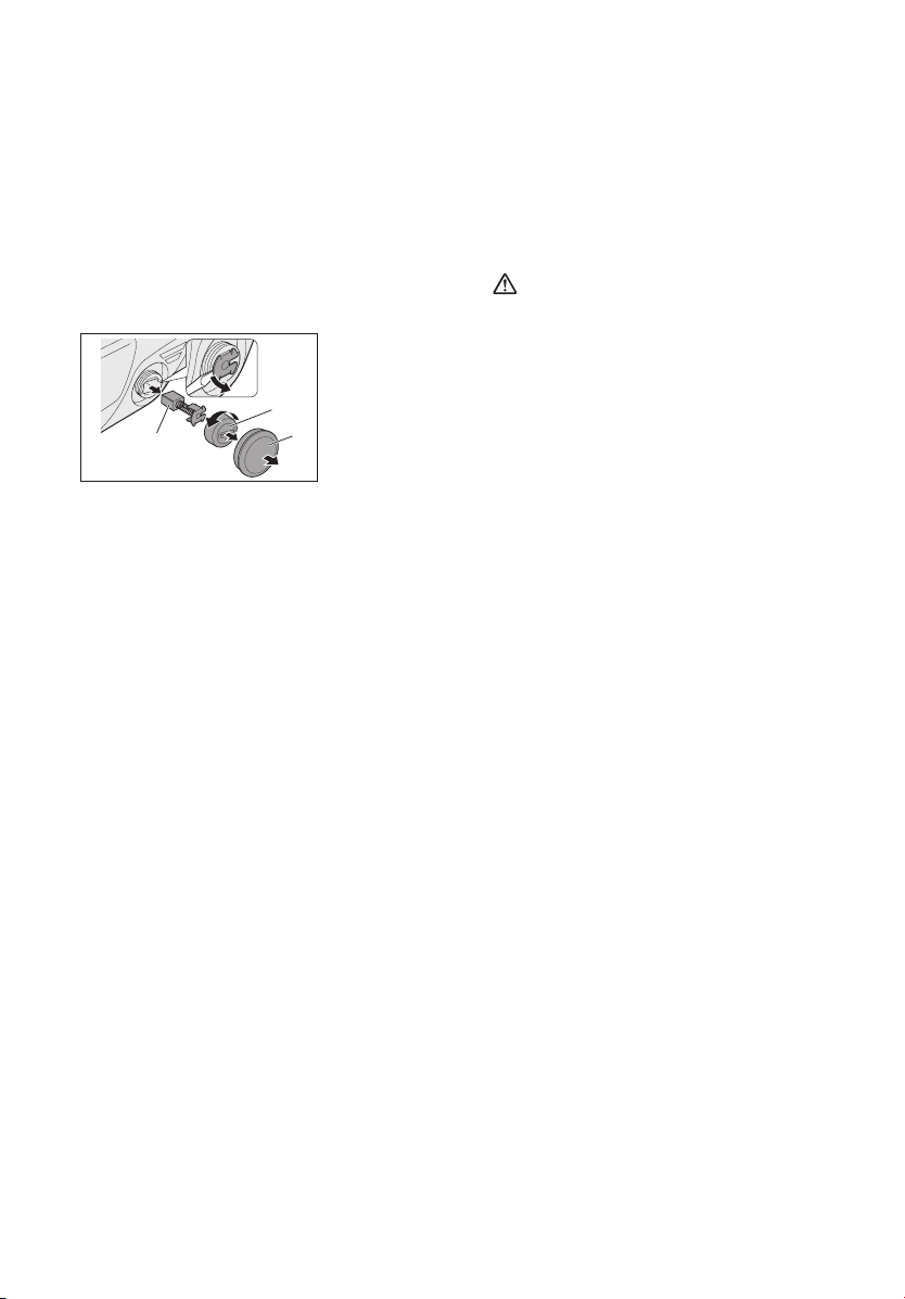
Replacing carbon brushes
Keep the carbon brushes clean and
free to slip in the holders. When it is
less than 5 mm (3/16”) shorter both
carbon brushes should be replaced at
the same time. Use only identical
carbon brushes.
Insert the top end of slotted bit screwdriver into the notch in the tool and
remove the brush cap cover by lifting it
up.
Carbon brush
Use a screwdriver to remove the caps.
Take out the worn carbon brushes, insert the new ones and secure the brush
caps.
Reinstall the brush cap cover on the
tool.
To maintain product SAFETY and RELIABILITY, repairs, any other maintenance or adjustment should be performed by Panasonic Authorized or
Factory Service Centers, always using
Panasonic replacement parts.
2
1
1. Brush cap
cover
2. Brush cap
V. MAINTENANCE
Use only a dry, soft cloth for wiping the
unit. Do not use a damp cloth, thinner,
benzine, or other volatile solvents for
cleaning.
VI. ACCESSORIES
CAUTION:
• The use of any accessories not
specified in this manual may result
in fire, electric shock, or personal
injury. Use recommended accessories only.
• Your tool is supplied with a guard for
use with a grinding disc. A cut-off
disc can also be used with a cut-off
disc guard. If you decide to use your
Panasonic grinder with approved
accessories which you purchase
from your Panasonic distributor or
factory service center, be sure to
obtain and use all necessary fasteners and guards as recommended in
this manual. Your failure to do so
could result in personal injury to you
and others.
Grinding Disc
• EY9X202E
Wheel diameter 115 mm (4-1/2”) x
6 mm (1/4”) x 22 mm (7/8”)
Grinding Disc Guard
• EY9X212E
Cut-off Disc
• EY9X203E
Wheel diameter 115 mm (4-1/2”) x
2.5 mm (3/32”) x 22 mm (7/8”)
Cut-off Disc Guard (For cut-off disc)
• EY9X213E
Disc Flange
• EY9X221E
Clamp Nut
• EY9X231E
- 19 -
Page 20

VII. SPECIFICATIONS
MAIN UNIT
Mounting wheel diameter 115 mm (4-1/2")
Mounting wheel innerhole diameter 22 mm (7/8")
Spindle thread size M14
Motor voltage 14.4 V DC
Rated speed 9500 min-1 (rpm)
Weight (with battery pack:EY9L40/EY9L41)
Overall length 361 mm (14-7/32")
Noise, Vibration See the included sheet
2.2 kg (4.8 lbs)
BATTERY PACK
Model
Storage battery
Battery voltage
Capacity
EY9L40
Li-ion Battery
14.4 V DC (3.6 V x 4 cells)
3 Ah
EY9L41
3,3 Ah
BATTERY CHARGER
Model
Rating
Weight
[Li-ion battery pack]
Charging time
Charging time
3 Ah
3,3 Ah
See the rating plate on the bottom of the charger.
14.4 V 21.6 V 28.8 V
EY9L40 EY9L60 EY9L80
Usable: 35 min.
Full: 50 min.
14.4 V
EY9L41
Usable: 45 min.
Full: 60 min.
EY0L80
g
0.95 k
(2.1 lbs)
Usable: 45 min.
Full: 60 min.
Usable: 55 min.
Full: 70 min.
- 20 -
Page 21
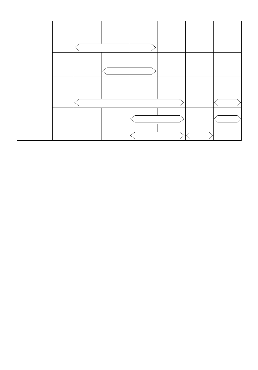
[Ni-Cd/Ni-MH battery pack]
7.2 V 9.6 V 12 V 15.6 V 18 V 24 V
Charging time
EY9065
1.2 Ah
1.7 Ah
2 Ah
3 Ah
3.5 Ah
EY9066
EY9168 EY9188
EY9080
EY9086
20 min.
EY9180
EY9182
EY9001
EY9006
EY9101
EY9103
25 min.
EY9106
EY9107
EY9108
30 min. 60 min.
EY9200 EY9230 EY9210
EY9201 EY9231 EY9251
EY9136
45 min.
55 min. 65 min.
EY9116
EY9117
90 min.
NOTE: This chart may include models that are not available in your area.
NOTE: For the dealer name and address, please see the included warranty card.
Please refer to the latest general catalogue.
- 21 -
Page 22
ONLY FOR U. K.
VIII. ELECTRICAL
PLUG INFORMATION
FOR YOUR SAFETY PLEASE READ
THE FOLLOWING TEXT CAREFULLY
This appliance is supplied with a moulded
three pin mains plug for your safety and
convenience.
A 5 amp fuse is fitted in this plug.
Should the fuse need to be replaced please
ensure that the replacement fuse has a rating of 5 amp and that it is approved by ASTA
or BSI to BS1362.
Check for the ASTA mark
on the body of the fuse.
If the plug contains a removable fuse cover
you must ensure that it is refitted when the
fuse is replaced.
If you lose the fuse cover the plug must not
be used until a replacement cover is obtained.
A replacement fuse cover can be purchased
from your local Panasonic Dealer.
IF THE FITTED MOULDED PLUG IS UNSUITABLE FOR THE SOCKET OUTLET IN
YOUR HOME THEN THE FUSE SHOULD
BE REMOVED AND THE PLUG CUT OFF
AND DISPOSED OF SAFELY.
THERE IS A DANGER OF SEVERE ELECTRICAL SHOCK IF THE CUT OFF PLUG IS
INSERTED INTO ANY 13 AMP SOCKET.
If a new plug is to be fitted please observe
the wiring code as shown below.
If in any doubt please consult a qualified
electrician.
or the BSI mark
IMPORTANT:
The wires in this mains lead are
coloured in accordance with the
following code:
Blue: Neutral
Brown: Live
As the colours of the wire in the mains lead
of this appliance may not correspond with
the coloured markings identifying the terminals in your plug, proceed as follows.
The wire which is coloured BLUE must be
connected to the terminal in the plug which
is marked with the letter N or coloured
BLACK.
The wire which is coloured BROWN must be
connected to the terminal in the plug which is
marked with the letter L or coloured RED.
Under no circumstances should either of
these wires be connected to the earth terminal of the three pin plug, marked with the
letter E or the Earth Symbol
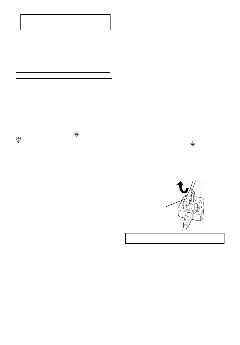
How to replace the fuse:
compartment with a screwdriver and replace the fuse and fuse cover if it is removable.
Fuse Cover
This apparatus was produced to BS800.
.
Open the fuse
- 22 -
Page 23
hinweise geringere Verletzungen zur Folge
I.BESTIMMUNGSGEMÄSSE
VERWENDUNG DER
MASCHINE
Vielen Dank, für den Kauf des
Panasonic-Winkelschleifers. Die
hervorragende Schleifleistung erfüllt
höchste Anforderungen und die
Unabhängigkeit von Netzanschlüssen
erlaubt einen vielseitigen Einsatz.
Dieser Winkelschleifer ist
ausschließlich für das Schleifen und
Trennschleifen vorgesehen.
GEFAHR:
Dieses Gerät ist ein Schleifwerkzeug zum
Schleifen. Durch die Schleifscheibe können
äußerst tiefe und sogar lebensgefährliche
Schnittverletzungen verursacht werden.
Lesen Sie daher unbedingt diese Anleitung
und die Vorsichtshinweise auf dem Werkzeug sorgfältig durch, und beachten Sie alle
Sicherheitsvorschriften und die zusätzlichen
Vorschriften, um solche Verletzungen zu
vermeiden.
WARNUNG:
Zur Verminderung der Verletzungsgefahr müssen zum Schleifen immer die
richtigen Schutze verwendet werden.
Hinweise zu dieser Anleitung
• Bitte lesen Sie sich diese Anleitung vor
der Inbetriebnahme des Winkelschleifers
vollständig durch. Falls eine weitere
Person diesen Winkelschleifer verwendet, sollten Sie darauf achten, dass auch
diese Person zuvor diese Anleitung liest
oder im Gebrauch des Winkelschleifers
und den Vorsichtsmaßregeln unterwiesen wurde.
• Diese Anleitung zum späteren Nachschlagen an einem sicheren Ort aufbewahren. Sie enthält wichtige Sicherheitshinweise, die beim Betrieb des
Winkelschleifers zu beachten sind.
• In dieser Anleitung und auf dem Produkt finden Sie folgende Signalwörter:
HINWEIS:
Gibt zusätzliche, nützliche Informationen zur
VORSICHT:
Verweist auf potentielle Gefahrensituationen,
die bei Missachtung der gegebenen Warn-
Winkelschleifer.
haben können. Solche Textstellen warnen
außerdem vor gefährlichen Vorgehensweisen.
WARNUNG:
Verweist auf potentielle Gefahren, die
bei Missachtung der gegebenen Warnhinweise zu schweren Verletzungen
oder Tod führen können.
GEFAHR:
Verweist auf eine Gefahr, die bei Missachtung der gegebenen Warnhinweise
zu ernsten Verletzungen oder Tod führt.
Lesen Sie bitte vor der ersten Inbetriebnahme dieses Geräts das separate
Handbuch „Sicherheitsmaßregeln“ sorgfältig durch.
II. WEITERE WICHTIGE
SICHERHEITSREGELN
Sicherheitsanweisungen für
alle Bedienungen
Allgemeine Sicherheitshinweise zum
Schleifen und Trennschleifen:
1)
Dieses Elektrowerkzeug ist für den
Einsatz als Schleif- oder Trennschleifmaschine vorgesehen.
Lesen Sie bitte alle diesem
Elektrowerkzeug beiliegenden
Warnungen, Anweisungen,
Abbildungen und technischen
Daten.
stehenden Anweisungen ist die
Gefahr eines elektrischen Schlags,
eines Brandausbruchs oder von
schweren Verletzungen vorhanden.
2)
Es wird nicht empfohlen
Bedienungen wie das
Sandpapierschleifen, Bürsten oder
Polieren mit diesem
Elektrowerkzeug vorzunehmen.
Anwendungen, für welche das
Elektrowerkzeug nicht vorgesehen ist,
können gefährliche Situationen und
Verletzungen verursachen.
3)
Nur speziell gefertigtes und vom
Werkzeughersteller empfohlenes
Zubehör verwenden.
Zubehör am Elektrowerkzeug anbringen lässt, ist damit noch kein sicherer
Betrieb garantiert.
Bei Nichtbeachtung der nach-
Wenn sich ein
- 23 -
Page 24

4)
Die Nenndrehzahl des Zubehörs muss
mindestens der Maximaldrehzahl des
Elektrowerkzeugs entsprechen.
das Zubehör mit höherer als der
NENNDREHZAHL betrieben wird, kann
es beschädigt werden.
5)
Der Außendurchmesser und die
Dicke des Zubehörs müssen innerhalb der Spezifikationen des
Elektrowerkzeugs liegen.
Zubehör in einer unzulässigen Größe
ist kein ausreichender Schutz bzw.
Kontrolle möglich.
6)
Die Größe der Scheiben, Flanschen, Auflagen und anderem Zubehör müssen richtig auf die
Spindel des Elektrowerkzeugs
passen.
Löchern verursachen Unwucht,
starke Vibrationen und können zu
Kontrollverlusten führen.
7)
Kein beschädigtes Zubehör verwenden. Vor jeder Inbetriebnahme
muss das Zubehör, wie die Schleifscheiben auf Splitterung und Risse
kontrolliert werden. Falls das
Elektrowerkzeug oder das Zubehör
fallen gelassen wurde, müssen die
Teile auf Beschädigung überprüft
bzw. ein unbeschädigtes Zubehör
verwendet werden. Nach abgeschlossener Prüfung und Installation des Zubehörs müssen Sie
sich und die Zuschauer außerhalb
des Bereichs der Ebene der rotierenden Scheibe begeben und das
Elektrowerkzeug bei Maximaldrehzahl ohne Belastung für eine
Minute lang einschalten.
digtes Zubehör bricht normalerweise
während dieser Testzeit auseinander.
8)
Schutzvorrichtungen verwenden. Je
nach Anwendung muss ein Gesichtsschutzschild oder eine
Schutzbrille getragen werden. Außerdem nach Bedarf eine Staubschutzmaske, einen Gehörschutz,
Handschuhe oder eine Schürze
tragen, die kleine Fragmente des
Werkstücks aufzufangen vermögen.
Der Augenschutz muss in der Lage
sein, weg geschleuderte Fragmente
von verschiedenen Anwendungen
aufzufangen.
in der Lage sein, weg geschleuderte
Fragmente von verschiedenen Anwen-
Zubehör mit unpassenden
Der Augenschutz muss
Falls
Für
Beschä-
- 24 -
dungen aufzufangen. Die Staubmaske
bzw. das Atemgerät muss die
entstehenden Staubpartikel wirksam
herausfiltern können. Eine langzeitige
Einwirkung lauter Geräusche kann zu
Gehörschäden führen.
9)
Zuschauer sollten sich in sicherer
Entfernung vom Arbeitsbereich
aufhalten. Personen, die sich in
den Arbeitsbereich begeben, müssen entsprechende Schutzvorrichtungen verwenden.
derte Fragmente vom Werkstück
oder von beschädigtem Zugehör können auch außerhalb des unmittelbaren Arbeitsbereichs Verletzungen
verursachen.
10)
Das Elektrowerkzeug zur
Bedienung nur am isolierten Griff
halten, wenn verborgene Kabel bzw.
das eigene Netzkabel
durchgeschnitten werden können.
Beim Durchschneiden von unter
Spannung stehenden Kabeln kann ein
elektrischer Schlag ausgelöst werden.
11)
Das Netzkabel entfernt von dem sich
drehenden Zubehör verlegen.
einem Kontrollverlust kann das Kabel
durchgeschnitten oder Ihre Hand oder
Ihr Arm kann in das sich drehende
Zubehör hineingezogen werden.
12)
Das Elektrowerkzeug niemals
ablegen, solange es sich noch
Das sich drehenden Zubehör
dreht.
kann hängen bleiben und das
Elektrowerkzeug kann außer
Kontrolle geraten.
13)
Das Elektrowerkzeug beim
Herumtragen nicht eingeschaltet
lassen.
Berührung mit der Bekleidung kann
das Zubehör an Ihren Körper
gezogen werden.
14)
Die Luftauslassöffnungen des
Elektrowerkzeugs müssen in regelmäßigen Abständen gereinigt
werden.
kann Staub ansaugen und wenn sich
im Gehäuse Metallstaub ansammelt,
besteht eine große Gefahr.
15)
Verwenden Sie das
Elektrowerkzeug nicht in der Nähe
von leicht entzündbaren Materialien.
Solche Materialien können durch
Funken entzündet werden.
Durch eine unfreiwillige
Das Gebläse des Motors
Weggeschleu-
Bei
Page 25

16)
Kein Zubehör verwenden, das flüssige Kühlmittel benötigt.
wendung von Wasser oder anderen
flüssigen Kühlmitteln besteht die
Gefahr eines elektrischen Schlags.
Bei Ver-
Weitere Sicherheitsanweisungen
für alle Anwendungen
Rückstoß und entsprechende Warnungen
Der Rückstoß ist die Reaktion auf eine
eingeklemmte oder blockierte Scheibe,
Unterlage, Bürste oder eines anderen
Zubehörs. Durch das Einklemmen oder
Blockieren wird die Drehung des Zubehörs sofort gestoppt und dadurch
entsteht eine Reaktionskraft auf die
Gegenseite der Drehrichtung des Zubehörs am Eingriffspunkt.
Falls zum Beispiel die Schleifscheibe
durch das Werkstück eingeklemmt oder
blockiert wird, kann die Kante der Scheibe am Eingriffspunkt in das Material eindringen, was die Rückstoßkraft erzeugt.
Je nach Bewegungsrichtung kann die
Scheibe am Eingriffspunkt gegen den
oder vom Bediener weg springen.
Schleifscheiben können unter diesen
Bedingungen auch brechen.
Rückstöße entstehen bei Missbrauch
oder Fehlbedienung des
Elektrowerkzeugs und deren
Bedienungen. Falls die richtigen
Vorsichtsmaßnahmen wie nachstehend
aufgeführt getroffen werden, lassen sich
Rückstöße vermeiden.
1)
Das Elektrowerkzeug muss fest gehalten werden, Rückstoßkräfte sollen
durch den Körper und die Arme aufgefangen werden können. Der Hilfsgriff,
falls vorhanden, muss immer verwendet werden, um die Kontrolle bei
auftretenden Rückstoß- und Drehkräften beim Einschalten nicht zu verlieren.
Der Bediener kann Rückstoß- und Drehkräfte unter Kontrolle halten, wenn die
richtigen Vorsichtsmaßnahmen getroffen
werden.
2)
Die Hand darf niemals in die Nähe
des sich drehenden Zubehörs gehalten werden.
kann die Hand vom Zubehör getroffen
werden.
3)
Der Körper darf sich nicht in dem
Bereich befinden, in den sich das
Elektrowerkzeug bei auftretenden
Bei Rückstoßkräften
- 25 -
Rückstoßkräften bewegt.
den Rückstoß wird das Tool beim
Blockieren in die Gegenrichtung der
Scheibenbewegung gedrückt.
4)
Besondere Vorsicht muss bei Ecken,
Kanten usw. angewendet werden.
Das Zubehör darf nicht anschlagen
oder blockiert werden.
scharfen Kanten besteht die Gefahr,
dass das sich drehende Zubehör
blockiert wird und durch die Rückstoßkräfte eine Kontrollverlust auftritt.
5)
Kein Kettensägeblatt oder ein gezähntes Sägeblatt anbringen.
Blätter verursachen häufig Rückstoßkräfte, die zu einem Kontrollverlust
führen können.
Durch
Bei Ecken und
Solche
Zusätzliche Sicherheitsanweisungen
zum Schleifen und Trennschleifen
Spezielle Sicherheitshinweise zum
Schleifen und Trennschleifen:
1)
Nur die für das Elektrowerkzeug empfohlenen Scheiben und den zur
verwendeten Scheibe entsprechende
Schutz verwenden.
nicht geeignet sind, ist keine
entsprechende Schutzvorrichtung vorhanden, deshalb gelten diese als unsicher.
2)
Der Schutz muss richtig am
Elektrowerkzeug angebracht
werden und für maximale
Sicherheit positioniert werden, so
dass möglichst ein kleiner Teil der
Scheibe gegen den Bediener
schaut.
vor Scheibenfragmenten und vor
einer unabsichtlichen Berührung der
Scheibe schützen.
3)
Die Scheiben dürfen nur für die
empfohlenen Anwendungen verwendet werden. Zum Beispiel: Die
Seite der Trennscheibe darf nicht
zum Schleifen verwendet werden.
Trennscheiben sind zum Schleifen
am Scheibenumfang, bei Belastung
solcher Scheiben mit Seitenkräften
können die Scheiben brechen.
4)
Nur unbeschädigte Scheibenflanschen mit der für die verwendete
Scheibe passenden Größe und Form
verwenden.
ringerung von Scheibenbrüchen durch
die richtigen Scheibenflansche gestützt.
Die Flansche für Trennscheiben kön-
Der Schutz soll den Bediener
Für Scheiben, die
Die Scheibe wird zur Ver-
Page 26
nen sich von Flanschen für Schleifscheiben unterscheiden.
5)
Keine abgenutzten Scheiben von
größeren Elektrowerkzeugen
verwenden.
größere Elektrowerkzeuge sind nicht
geeignet für die höheren Drehzahlen
der kleineren Tools und können
brechen.
Die Scheiben für
Zusätzliche Sicherheitsanweisungen
zum Trennschleifen:
1)
Die Trennscheibe darf nicht eingeklemmt oder mit übermäßigen
Kräften belastet werden. Nicht versuchen eine übermäßige Schnitttiefe zu erreichen.
spruchung der Scheibe führt zu einer
erhöhten Belastung und die Möglichkeit eines Verdrehens oder Blockierens im Schnitt erhöht sich, was zu
Rückstoßkräften oder zu einem
Scheibenbruch führen kann.
2)
Der Körper darf sich nicht in einer
Linie oder hinter der Scheibe befinden.
vom Körper weg bewegt wird, erfolgt
ein möglicher Rückstoß des
Elektrowerkzeugs direkt gegen den
Körper.
3)
Bei blockierter Scheibe oder bei
einer Unterbrechung des Trennschleifens muss das
Elektrowerkzeug ausgeschaltet
und still gehalten werden, bis sich
die Scheibe nicht mehr dreht. Nicht
versuchen die Trennscheibe in
drehendem Zustand zu entfernen,
weil dabei ein Rückstoß auftreten
kann.
Scheibenblockierung herausfinden
und beheben.
4)
Beim Fortsetzen darf sich die
Trennscheibe nicht im Werkstück
befinden. Die Scheibe muss die
volle Drehzahl erreicht haben,
bevor sie ins Werkstück eingeführt
wird.
Scheibe im Werkstück befindet, können Rückstoßkräfte auftreten.
Wenn im Betrieb die Scheibe
Die Ursache der
Wenn sich beim Start die
Eine Überbean-
5)
Platten oder große Werkstücke
müssen zur Verminderung der Einklemmgefahr und möglicher Rückstoßkräfte gestützt werden.
Werkstücke können durch das Eigengewicht durchhängen. Deshalb müssen sie in der Nähe der Trennlinie an
beiden Werkstückkanten gestützt
werden.
6)
Für einen „Taschenschnitt“ in
Große
bestehenden Wänden oder
anderen Blindbereichen muss
besondere Vorsicht angewendet
werden.
Die vorstehende Scheibe
kann Gas- oder Wasserleitungen,
elektrische Kabel oder Gegenstände trennen, was
Rückstoßkräfte verursachen kann.
Symbol Bedeutung
V
n
…min
Ah
Drehzahl oder Hubzahl
-1
Akkukapazitat in Ampere
Zur Verminderung der
Verletzungsgefahr muss
die Bedienungsanleitung
gründlich gelesen werden.
Nur für Inneneinsatz.
Augenschutz tragen
Volt
Gleichstrom
Nenndrehzahl
pro Minute
Stunden
Immer einen
- 26 -
Page 27
A
III. BAUGRUPPE
HINWEIS:
Zum Anbringen oder Entfernen eines
Seitengriffs muss der Akku entfernt
werden.
VORSICHT:
• Vor der Inbetriebnahme immer kontrollieren, ob der Seitengriff sicher
angebracht ist.
Den Seitengriff wie in der Abbildung
gezeigt richtig einschrauben.
VORSICHT:
• Bei sich drehender Spindel darf der
Sicherungsstift niemals betätigt
werden. Das Tool kann dabei
beschädigt werden.
Die Verriegelungstaste drücken, wenn
sich die Spindel nicht drehen soll, wie
zum Ein- oder Ausbau von Teilen wie
Schleifscheiben, Scheibenschutz usw.
Installieren und Entfernen der
Scheibe
Prüfung vor der Inbetriebnahme
• Ist die richtige Schleifscheibe für
den zu schneidenden Gegenstand
eingesetzt?
• Ist eine Schleifscheibe der
richtigen Größe eingesetzt?
•
Entspricht die eingesetzte
Schleifscheibe der nachstehend
aufgeführten Sicherheitsbestimmungen?
Europa - EN, Australien - AS
1.Schleifscheibe
1
2.Spindel
3.Schleifscheibe
3
2
nschutz
nschutzschrau
be
VORSICHT:
• Bei der Verwendung muss der
Schleifscheibenschutz immer am
Tool installiert sein, so dass die
geschlossene Seite des Schutzes
gegen den Bediener gerichtet ist.
• Stellen Sie sicher, dass
Beilegscheiben verwendet werden,
wenn diese mit Schleifscheiben
aus gebundenem Schleifmittel
mitgeliefert werden und wenn
diese erforderlich sind;
WARNUNG:
• Zum Trennschleifen muss immer
der mitgelieferte Schutz verwendet
werden. Die Schleifscheibe kann
während der Anwendung brechen
und mit dem Schleifscheibenschutz
lässt sich die Verletzungsgefahr
vermindern.
1.
Den Schleifscheibenschutz installieren
und die Schraube richtig festziehen.
uf die richtige
Richtung der
Seite achten.
1
2
3
2. Den Scheibenflansch und die Scheibe
in der abgebildeten Reihenfolge auf
die Spindel setzen.
3. Die Mutter auf der Spindel festziehen, so dass die gewölbte Seite
auf die Gegenrichtung der Scheibe
gerichtet ist.
4. Die Spindelverriegelungstaste hineindrücken, um die Spindel festzustellen
und die Mutter mit dem Klemmenmutterschlüssel festziehen.
1
- 27 -
1. Mutter
2. Schleifscheibe
3. Scheibenflansch
1. Spindel-
verriegelungstaste
Page 28
f
A
5. Zum Entfernen der Schleifscheibe
die Installationsschritte in der
umgekehrten Reihenfolge
ausführen.
Anbringen oder Abnehmen
des Akkus
1. Zum Anschließen des Akkus:
Die Ausrichtmarkierungen aufeinander
ausrichten, und den Akku anbringen.
• Den Akku einschieben, bis er einrastet.
usricht-
markierungen
2. Zum Entfernen des Akkus:
Zum Abnehmen des Akkus den Knopf
an der Vorderseite drücken.
Knop
IV. BETRIEB
HINWEIS:
Weil kein Anschluss an einer Netzsteckdose notwendig ist, befindet sich
dieses Tool immer in betriebsbereitem Zustand.
Einschalterbedienung
1
VORSICHT:
• Vor dem Einsetzen des Akkus in das
Tool muss geprüft werden, ob sich
der Einschalter richtig bedienen lässt
und in die Position „AUS“ zurückkehrt, wenn er hintere Schalterteil
gedrückt wird.
• Der Einschalter kann in der „EIN“Position festgestellt werden. Passen
Sie beim Feststellen des Einschalters
in der „EIN“-Position auf und halten
Sie den Stützgriff und den Griff richtig
fest.
Drücken Sie den Einschalter zum Einschalten und schieben Sie ihn gegen die
„EIN“-Position. Drücken Sie für einen
kontinuierlichen Betrieb die vordere
Seite des Einschalters zum Feststellen.
Drücken Sie den hinteren Teil des Einschalters zum Ausschalten und schieben Sie ihn gegen die „AUS“-Position.
WARNUNG:
• Auf das Tool sollte keine übermäßigen
Kräfte angewendet werden. Das Gewicht des Tools erzeugt einen ausreichenden Druck. Durch Kraftanwendung
und übermäßigen Druck kann ein Bruch
der Schleifscheibe verursacht werden.
• Falls das Tool beim Schleifen fallen
gelassen wurde, muss die Schleifscheibe IMMER ausgetauscht werden.
• Die Schleifscheibe darf nicht angeschlagen werden.
• Vermeiden Sie das Hüpfen oder
Blockieren der Schleifscheib,
besonders beim Arbeiten an Ecken,
scharfen Kanten usw. Dadurch kann
ein Verlust der Kontrolle verursacht
werden und es können Rückstoßkräfte auftreten.
VORSICHT:
• Schalten Sie am Ende das Tool immer
aus und warten Sie bis sich die
Scheibe nicht mehr dreht, bevor Sie
das Tool ablegen.
1. Netzschalter
- 28 -
Page 29
A
Sichtprüfung und
Scheibenbetriebsprüfung
1. Kontrollieren Sie vor der Inbetriebnahme immer, ob die Scheibe keine
Risse aufweist.
2. Führen Sie immer die folgende
Betriebsprüfung aus.
3. Die Scheibe muss immer richtig
befestigt werden.
Neue Scheibe mehr als 3 Min.
Vor Verwendung
der gegenwärtigen
Scheibe
Zeit
mehr als 1 Min.
Schleifen
AB
Halten Sie das Tool IMMER mit der
einen Hand am Griff und mit der
anderen Hand am Seitengriff fest.
Schalten Sie das Tool ein und halten
Sie die Scheibe an das Werkstück.
Halten Sie im allgemeinen die Schleifscheibe in einem Winkel von ungefähr
15 Grad zur Werkstückoberfläche.
Bei Verwendung einer neuen Schleifscheibe darf der Winkelschleifer nicht
in Richtung B bewegt werden, weil
sonst das Werkstück angeschnitten
wird. Nachdem die Kanten der neuen
Schleifscheibe durch die Verwendung
abgerundet sind, kann die Schleifscheibe in beiden Richtungen A und
B verwendet werden.
Trennscheibenschutz
(EY9X213E) (als Sonderzubehör
erhältlich)
uf die richtige Richtung
der Seite achten.
WARNUNG:
• Bei Verwendung einer Trennscheibe
muss der entsprechende Trennscheibenschutz verwendet werden.
• Eine Trennscheibe darf NIEMALS
zum Schleifen verwendet werden.
• Die Trennscheibe darf nicht eingeklemmt oder mit übermäßigen
Kräften belastet werden. Nicht versuchen eine übermäßige Schnitttiefe zu erreichen. Eine Überbeanspruchung der Trennscheibe führt
zu einer erhöhten Belastung und die
Möglichkeit eines Verdrehens oder
Blockierens im Schnitt und einer
Motorüberhitzung erhöht sich.
• Nicht einschalten, wenn sich die
Scheibe im Werkstück befindet. Dadurch kann die Trennscheibe blockiert werden und es können
Rückstoßkräfte auftreten. Die Scheibe muss die volle Drehzahl erreicht
haben, bevor sie ins Werkstück
eingeführt wird.
• Während des Trennschleifens darf
der Winkel der Scheibe nicht geändert werden. Bei Anwendung von
Seitenkräften (wie beim Schleifen)
auf die Trennscheibe kann die
Scheibe reißen und brechen, so
dass eine hohe Verletzungsgefahr
vorhanden ist.
VORSICHT:
• Um übermäßigen Temperaturanstieg der Werkzeugoberfläche zu
vermeiden, sollte das Werkzeug
nicht kontinuierlich mit zwei oder
mehr Akkus betrieben werden. Das
Werkzeug muss vor dem Akkuwechsel abkühlen.
- 29 -
Page 30
A
A
A
g
A
• Blockieren Sie nicht die seitlichen
Ventilationsöffnungen des Gehäuses während des Betriebs. Anderenfalls wird die Maschinenfunktion
beeinträchtigt, was zu einem Ausfall führen kann.
• Überlasten Sie den Motor des
Werkzeugs nicht. Hierdurch kann
die Maschine beschädigt werden.
• Halten Sie das Tool so, dass die
Abluft von den Ventilationsöffnungen
im Gehäuse nicht direkt gegen Ihre
Haut geblasen wird. Anderenfalls
können Sie sich verbrennen.
Anzeige für Sicherungswarnfunktion
Der Winkelschleifer lässt sich nicht
einschalten, wenn sich der Schalter in
der Position „EIN“ befindet (Schalterhebel auf „EIN“), selbst bei eingesetztem Akku. Die Warnleuchte blinkt,
um anzuzeigen dass die Einschaltsicherung betätigt wurde.
Stellen Sie den Schalter in die Position
„AUS“ (Schalterhebel auf „AUS“) und
drücken Sie den Schalter wieder in die
Position „EIN“ (Schalterhebel auf „EIN“)
zurück.
EIN
US
Überhitzungs-Warnlampe
us
(normaler
Betrieb)
Die Überhitzungs-Schutzfunktion hält
den betrieb an, um den Akku im Falle
einerÜberhitzung zu schützen. Wenn
diese Funktion aktiv ist, blinkt die
Überhitzungs-Warnlampe am Bedienfeld.
• Falls die Überhitzungs-Schutzfunktion
aktiviert wird, lassen Sie das Gerät
gründlich abkühlen (mindestens 30
Minuten). Der Akku ist wieder einsatzbereit, wenn die Überhitzungs-Warnlampe erlischt.
• Vermeiden Sie Arbeitsgänge, die dazu
führen, dass der Überhitzungsschutz
mehrfach aktiviert wird.
Blinken: Überhitzung
Zeigt an, dass der Betrieb
wegen Akku-Überhitzung
an
ehalten wurde.
Akkuladungs-Warnlampe
us
(normaler
Betrieb)
- 30 -
Blinken
(Keine Ladung)
kkuschutzfunktion
aktiv
Page 31

Übermäßiges (vollständiges) Entladen
von Li-Ion-Akkus führt zu einer erheblichen Verkürzung ihrer Lebensdauer. Das
Tool ist mit einer Akkuschutzfunktion
ausgestattet, die übermäßiges Entladen
des Akkus verhindert.
• Die Akkuschutzfunktion wird
unmittelbar vor der Erschöpfung des
Akkus aktiviert und bewirkt Blinken
der Akkuladungs-Warnlampe.
• Wenn Sie bemerken, dass die Akkuladungs-Warnlampe blinkt, laden Sie
den Akku unverzüglich auf.
- Einschaltsicherungsfunktion
- Wenn bei eingesetztem Akku der
Einschalter auf „EIN“ gestellt wird,
kann in diesem Fall das Tool nicht
eingeschaltet werden. Die Leuchte
blinkt langsam, um anzuzeigen, dass
die Einschaltsicherungsfunktion aktiviert ist.
- Zum Einschalten muss der Einschalter
zuerst auf „AUS“ gestellt und danach
in die Position „EIN“ geschoben
werden.
[Akku]
Für richtigen Gebrauch des
Akkus
Li-Ion-Akku (EY9L40/ EY9L41)
• Um eine möglichst lange Lebensdauer des Li-Ion-Akkus zu erzielen,
lagern Sie ihn nach dem Gebrauch,
ohne ihn aufzuladen.
• Achten Sie beim Laden des Akkus
darauf, dass die Kontakte am Ladegerät frei von Fremdstoffen, wie z. B.
Staub und Wasser usw., sind. Reinigen Sie die Kontakte vor dem Laden
des Akkus, falls Fremdstoffe auf den
Kontakten vorhanden sind.
Die Lebensdauer der Akkukontakte
kann durch Anhaften von Fremdstoffen, wie z. B. Staub und Wasser
usw., während des Betriebs beeinträchtigt werden.
- 31 -
• Wenn Sie den Akku nicht benutzen,
halten Sie ihn von Metallgegenständen fern: Büroklammern, Münzen,
Schlüssel, Nägel, Schrauben oder
andere kleine Metallgegenstände
können die Kontakte kurzschließen.
Das Kurzschließen der Akkukontakte
kann Funken, Verbrennungen oder
einen Brand verursachen.
• Sorgen Sie bei Benutzung des Akkus
für ausreichende Belüftung des Arbeitsplatzes.
• Wenn der Akku vom WerkzeugHauptteil abgenommen wird, ist die
Akkuabdeckung sofort anzubringen,
um zu verhüten, dass die Akkukontakte durch Staub oder Schmutz
verunreinigt werden und ein Kurzschluss verursacht wird.
Lebensdauer des Akkus
Der Akku hat nur eine begrenzte
Lebensdauer. Wenn auch nach einer
ordnungsgemäßen Ladung die Betriebszeit extrem kurz ist, muss der
Akku erneuert werden.
Batterie-Recycling
ACHTUNG:
Um Umweltschutz und MaterialRecycling zu gewährleisten, müssen Sie die Batterie zur örtlichen
Entsorgungsstelle bringen, falls eine
solche in Ihrem Land vorhanden ist.
[Ladegerät]
Laden
Vorsichtsmaßnahmen für
Li-Ion Akku
• Wenn die Temperatur des Akkus
unter ca. -10°C (14°F) sinkt, wird der
Ladevorgang automatisch abgebrochen, um eine Schädigung des
Akkus zu vermeiden.
Page 32

A
Allgemeine Vorsichtsmaßnahmen
für Li-Ion/Ni-MH/Ni-Cd-Akkus
• Der Umgebungstemperaturbereich
liegt zwischen 0°C und 40°C.
Wenn der Akku bei einer Akkutempera-
tur unter 0°C benutzt wird, funktioniert
die Maschine möglicherweise nicht einwandfrei.
• Wenn ein kalter Akku (von etwa 0°C
oder weniger) in einem warmen Raum
aufgeladen werden soll, lassen Sie
den Akku für mindestens eine Stunde
in dem Raum und laden Sie ihn auf,
wenn er sich auf Raumtemperatur
erwärmt hat.
• Den Akku abkühlen lassen, wenn er
mehr als 2× hintereinander aufgeladen wurde.
• Während dem Aufladen kann sich
das Ladegerät leicht erwärmen. Das
ist normal. Der Akku darf NICHT zu
lange aufgeladen werden.
VORSICHT:
Um die Gefahr eines Brandes oder
Schadens am Ladegerät zu verhindern.
• Keinen Motorgenerator als Spannungsquelle benutzen.
• Decken Sie die Entlüftungsöffnungen des Ladegerätes und den Akku
nicht ab.
• Trennen Sie das Ladegerät vom
Stromnetz, wenn es nicht benutzt
wird.
Li-Ion-Akku
HINWEIS:
Beim Kauf ist Ihr Akku nicht voll
aufgeladen. Laden Sie daher den
Akku vor Gebrauch auf.
Ladegerät (EY0L80)
1. Ladegerät an Wandsteckdose anschließen.
HINWEIS:
Beim Einführen des Steckers in
eine Netzsteckdose können Funken erzeugt werden, was jedoch in
Bezug auf die Sicherheit kein Problem darstellt.
2. Akku fest in das Ladegerät schieben.
1. Die Ausrichtmarkierungen ausrichten, und den Akku in den Schacht
des Ladegerätes einsetzen.
2. In Pfeilrichtung nach vorn schieben.
usrichtmarkierungen
3. Während des Ladens leuchtet die
Ladekontrolllampe.
Mit Erreichen der vollen Ladung
spricht automatisch eine interne,
elektronische Schaltung an, die ein
Überladen verhindert.
• Das Laden beginnt nicht, solange der
Akku noch heiß ist (wie z.B. unmittelbar nach intensivem Gebrauch).
Die Bereitschaftslampe blinkt in Orange, bis der Akku abgekühlt ist.
Das Laden beginnt dann automatisch.
4. Die Ladekontrolllampe (grün) blinkt
langsam, wenn der Akku zu etwa
80% aufgeladen ist.
5. Wenn der Ladevorgang beendet ist,
beginnt die Ladekontrolllampe
schnell in Grün zu blinken.
6. Falls die Akkutemperatur 0°C oder
weniger beträgt, dauert der Ladevorgang bis zur vollen Aufladung
des Akkus länger als die normale
Ladezeit. Selbst wenn der Akku voll
aufgeladen ist, hat er nur etwa 50%
der Leistung eines voll aufgeladenen Akkus bei normaler Betriebstemperatur.
7. Falls die Betriebslampe nicht unmittelbar nach dem Anschluss des
Ladegeräts aufleuchtet oder die
Ladekontrolllampe nach Ablauf der
normalen Ladezeit nicht schnell in
Grün blinkt, konsultieren Sie ein
autorisiertes Kundendienstzentrum.
- 32 -
Page 33

8. Wird ein voll aufgeladener Akku
erneut in das Ladegerät eingesetzt,
leuchtet die Ladekontrolllampe auf.
Nach einigen Minuten beginnt die
Ladekontrolllampe rascher zu blinken
und zeigt an, dass der Ladevorgang
abgeschlossen ist.
Ni-MH/Ni-Cd-Akku
HINWEIS:
Beim ersten Aufladen der Akkus
oder beim Aufladen nach längerer
Ruhezeit die Akkus etwa 24 Stunden
lang aufladen, um die volle Kapazität
zu erreichen.
Ladegerät (EY0L80)
1. Ladegerät an Wandsteckdose anschließen.
HINWEIS:
Beim Einführen des Steckers in
eine Netzsteckdose können Funken erzeugt werden, was jedoch in
Bezug auf die Sicherheit kein Problem darstellt.
2. Akku fest in das Ladegerät schieben.
5. Wenn die Ladekontrolllampe nicht
unmittelbar nach dem Anschließen
des Netzkabels aufleuchtet oder
nach Ablauf der normalen Ladezeit
nicht erlischt, wenden Sie sich bitte
an ein autorisiertes Kundendienstzentrum.
6. Wird ein voll aufgeladener Akku
erneut in das Ladegerät eingesetzt,
leuchtet die Ladekontrolllampe auf.
Nach einigen Minuten beginnt die
Ladekontrolllampe rascher zu blinken
und zeigt an, dass der Ladevorgang
abgeschlossen ist.
3. Während des Ladens leuchtet die
Ladekontrolllampe.
Mit Erreichen der vollen Ladung
spricht automatisch eine interne,
elektronische Schaltung an, die ein
Überladen verhindert.
• Das Laden beginnt nicht, solange der
Akku noch heiß ist (wie z.B. unmittelbar nach intensivem Gebrauch).
Die Bereitschaftslampe blinkt in
Orange, bis der Akku abgekühlt ist.
Das Laden beginnt dann automatisch.
4. Wenn der Ladevorgang beendet ist,
beginnt die Ladekontrolllampe schnell
in Grün zu blinken.
- 33 -
Page 34

ANZEIGELAMPEN
Leuchten in Grün
Das Ladegerät ist an eine Netzsteckdose angeschlossen.
Ladebereitschaft hergestellt.
Schnelles Blinken in Grün
Ladevorgang ist abgeschlossen. (Volle Ladung)
Blinken in Grün
Der Akku ist zu etwa 80 % aufgeladen. (Nutzbare Ladung.
Nur Li-Ion)
Leuchten in Grün
Ladevorgang läuft.
Leuchten in Orange
Akku ist kalt.
Der Akku wird langsam geladen, um seine Belastung zu
reduzieren.
Blinken in Orange
Der Akku ist warm geworden. Der Ladevorgang beginnt
wieder, wenn dieTemperatur des Akku gefallen ist.
Beträgt die Temperatur des Akkus –10°C oder weniger,
beginnt die Ladekontrolllampe (orange) ebenfalls zu blinken.
Der Ladevorgang beginnt, wenn die Temperatur des Akkus
steigt (nur Li-Ion)
Ladezustandslampe
Links: Grün Rechts: Orange wird angezeigt.
Schnelles Blinken in Orange und Grün
Keine Ladung möglich.Verstaubt oder Defekt des Akkus.
- 34 -
Page 35

Benutzerinformation zur Sammlung und Entsorgung von
veralteten Geräten und benutzten Batterien
Diese Symbole auf den Produkten, Verpackungen und/oder Begleitdokumenten bedeuten, dass benutzte elektrische und elektronische Produkte
und Batterien nicht in den allgemeinen Hausmüll gegeben werden sollen.
Bitte bringen Sie diese alten Produkte und Batterien zur Behandlung, Aufarbeitung bzw. zum Recycling gemäß Ihrer Landesgesetzgebung und den
Richtlinien 2002/96/EG und 2006/66/EG zu Ihren zuständigen Sammelpunkten.
Indem Sie diese Produkte und Batterien ordnungsgemäß entsorgen, helfen Sie
dabei, wertvolle Ressourcen zu schützen und eventuelle negative Auswirkungen auf die menschliche Gesundheit und die Umwelt zu vermeiden, die
anderenfalls durch eine unsachgemäße Abfallbehandlung auftreten können.
Wenn Sie ausführlichere Informationen zur Sammlung und zum Recycling
alter Produkte und Batterien wünschen, wenden Sie sich bitte an Ihre
örtlichen Verwaltungsbehörden, Ihren Abfallentsorgungsdienstleister oder
an die Verkaufseinrichtung, in der Sie die Gegenstände gekauft haben.
Gemäß Landesvorschriften können wegen nicht ordnungsgemäßer Entsorgung dieses Abfalls Strafgelder verhängt werden.
Für geschäftliche Nutzer in der Europäischen Union
Wenn Sie elektrische oder elektronische Geräte entsorgen möchten, wenden Sie sich
wegen genauerer Informationen bitte an Ihren Händler oder Lieferanten.
[Informationen zur Entsorgung in Ländern außerhalb der
Europäischen Union]
Diese Symbole gelten nur innerhalb der Europäischen Union. Wenn Sie solche Gegenstände entsorgen möchten, erfragen Sie bitte bei den örtlichen Behörden oder Ihrem
Händler, welches die ordnungsgemäße Entsorgungsmethode ist.
Hinweis zum Batteriesymbol (unten zwei Symbolbeispiele):
Dieses Symbol kann in Kombination mit einem chemischen Symbol verwendet werden.
In diesem Fall erfüllt es die Anforderungen derjenigen Richtlinie, die für die betreffende
Chemikalie erlassen wurde.
- 35 -
Page 36

Austauschen der Kohlenbürsten
Halten sie die Kohlenbürsten sauber,
so dass sie in den Haltern frei
schleifen können. Falls sie weniger
als 5 mm (3/16") kürzer ist, müssen
beide Kohlenbürsten miteinander
ausgetauscht werden. Es dürfen nur
identische Kohlenbürsten verwendet
werden.
Setzen Sie das Ende eines Schlitz-BitSchraubendrehers in die Kerbe am
Ende des Tools und heben Sie die
Bürstenkappenabdeckung ab.
Kohlenbürste
2
1
1. Bürstenkappenabdeckung
2. Bürstenkappe
Entfernen Sie die Kappen mit einem
Schraubendreher. Nehmen Sie die
abgenutzten Kohlebürsten heraus,
setzen Sie die neuen Bürsten ein und
sichern Sie die Bürstenkappen.
Bringen Sie die Bürstenkappenabdeckung wieder am Tool an.
Für die Einhaltung der PRODUKTSICHERHEIT und ZUVERLÄSSIGKEIT sollten Reparaturen, Wartungsarbeiten und Einstellungen stets von
einem autorisierten Panasonic Kundendienst ausgeführt und ausschließlich die richtigen Panasonic-Ersatzteile verwendet werden.
V. WARTUNG
Zum Abwischen der Einheit verwenden
Sie ausschließlich ein trockenes, weiches Tuch. Verwenden Sie kein feuchtes Tuch, Verdünner, Benzin oder andere flüchtige Lösungsmittel zum Reinigen.
VI. ZUBEHÖR
VORSICHT:
• Die Verwendung von anderen Zubehörteilen, die nicht in dieser Anleitung aufgeführt sind, kann zu
Brand, elektrischen Schlägen oder
Verletzungen führen. Verwenden
Sie ausschließlich das empfohlene
Zubehör.
• Mit dem Tool wird ein Schutz für die
Verwendung mit einer Schleifscheibe
mitgeliefert. Mit einem entsprechenden Trennscheibenschutz lässt sich
auch eine Trennscheibe verwenden.
Für die Verwendung des Panasonic-
-Winkelschleifers mit empfohlenem
Zubehör, die bei einem PanasonicVerteiler oder einem Kundendienst
erhältlich sind, müssen auch alle
notwendigen Befestigungselemente
und Schutze, deren Verwendung in
dieser Bedienungsanleitung empfohlen wird, beschafft werden. Bei Missachtung besteht eine hohe Verletzungsgefahr.
Schleifscheibe
• EY9X202E
Scheibendurchmesser 115 mm
(4-1/2) x 6 mm (1/4") x 22 mm (7/8")
Schleifscheibenschutz
• EY9X212E
Trennscheibe
• EY9X203E
Scheibendurchmesser 115 mm
(4-1/2) x 2,5 mm (3/32") x 22 mm
(7/8")
Trennscheibenschutz
(für Trennscheibe)
• EY9X213E
Scheibenflansch
• EY9X221E
Mutter
• EY9X231E
- 36 -
Page 37

VII. TECHNISCHE DATEN
HAUPTGERÄT
Scheibendurchmesser 115 mm (4-1/2")
Scheibenlochdurchmesser 22 mm (7/8")
Spindelgewinde M14
Motorspannung 14,4 V DC
Nenndrehzahl 9500 min-1 (rpm)
Gewicht (mit Akku: EY9L40/EY9L41)
Gesamtlänge 361 mm (14-7/32")
Geräusche, Vibration Siehe beiliegendes Blatt
2,2 kg (4,8 lbs)
AKKU
Modell
Akku
Nennspannung
Nennkapazität
EY9L40
Li-Ion-Akku
14,4 V DC (3,6 V × 4 Zellen)
3 Ah 3,3 Ah
EY9L41
AKKU-LADEGERÄT
Modell
Nennleistung
Gewicht
[Li-Ion-Akku]
Ladezeit
Ladezeit
3 Ah
3,3 Ah
Siehe Leistungsschild auf der Unterseite des Ladegerätes.
14,4 V 21,6 V 28,8 V
EY9L40 EY9L60 EY9L80
Nutzbar: 35 Min.
Voll: 50 Min.
14,4 V
EY9L41
Nutzbar: 45 Min.
Voll: 60 Min.
EY0L80
g
0,95 k
(2,1 lbs)
Nutzbar: 45 Min.
Voll: 60 Min.
Nutzbar: 55 Min.
Voll: 70 Min.
- 37 -
Page 38

[Ni-MH/Ni-Cd-Akku]
7,2 V 9,6 V 12 V 15,6 V 18 V 24 V
Ladezeit
EY9065
1,2 Ah
1,7 Ah
2 Ah
3 Ah
3,5 Ah
EY9066
EY9168 EY9188
EY9080
EY9086
20 Min.
EY9180
EY9182
EY9001
EY9006
EY9101
EY9103
25 Min.
EY9106
EY9107
EY9108
30 Min. 60 Min.
EY9200 EY9230 EY9210
EY9201 EY9231 EY9251
EY9136
45 Min.
55 Min. 65 Min.
EY9116
EY9117
90 Min.
HINWEIS: Diese Tabelle kann Modelle enthalten, die möglicherweise in Ihrem
Wohnge biet nicht angeboten werden.
Bitte nehmen Sie auf den neusten Generalkatalog Bezug.
HINWEIS: Name und Adresse des Händlers entnehmen Sie bitte der beiliegenden
Garantiekarte.
- 38 -
Page 39

I. USAGE PREVUI. USAGE PREVU
Merci d'avoir acheté la meule d'angle
Panasonic. L'action de meulage puissante de cet outil, combinée avec la
commodité de sa batterie autonome rechargeable, vous offre un excellent résultat de meulage.
Cette meule d'angle ne doit être utilisée
que pour meuler et tronçonner.
MISE EN GARDE:
Les mises en garde signalent des situations présentant un danger réel pouvant
se traduire par des blessures superficielles ou moyennes si elles ne sont
pas abandonnées. Les mises en garde
rappellent aussi que les pratiques envisagées qui ne sont pas sûres doivent
être abandonnées.
DANGER:
Ce produit est un outil de meulage,
concu pour meuler. Il a un disque rotatif
qui est capable de vous couper en profondeur, résultant en des blessures graves ou la mort. Il en résulte que, veuillez
lire soigneusement cette notice et les signes d'avertissement sur l'outil, et obéissez à toutes les Instructions de sécurité
afin d'éviter lesdites blessures.
AVERTISSEMENT:
Pour réduire le risque de blessure, utilisez toujours des protections propres
lors du meulage.
Comment se servir de cette
notice
Veuillez lire entièrement la présente
•
notice avant de commencer à utiliser
votre scie circulaire à bois. Si vous
laissez une autre personne utiliser la
scie circulaire à bois, veillez à ce que
cette personne ait lu cette notice ou
ait été complètement informée de la
méthode d'utilisation correcte et de
toutes les précautions de sécurité relatives à la scie circulaire à bois.
Veuillez conserver cette notice pour
•
consultation ultérieure. Elle contient
des consignes de sécurité importantes que vous devez suivre absolument pour utiliser la scie circulaire à
bois en toute sécurité.
Dans cette notice et sur l'outil figurent
•
les termes de signalisation suivants:
REMARQUE:
Les remarques fournissent des renseignements complémentaires utiles qu'il
est important de savoir à propos de la
scie circulaire.
AVERTISSEMENT:
Les avertissements signalent des situations présentant un danger réel pouvant se traduire par des accidents graves voire entraîner la mort si elles ne
sont pas évitées.
DANGER:
Les rappels de danger signalent un risque imminent pouvant se traduire par
des accidents graves voire entraîner la
mort s'il n'est pas évité.
Veuillez lire le livret «Instructions de sécurité» et les instructions suivantes avant
d'utiliser l'outil.
II. REGLES DE II. REGLES DE
SECURITE ADDI-SECURITE ADDI-
TIONNELLESTIONNELLES
Instructions de sécurité pour
toutes les utilisations
Consignes de sécurité spécifiques
aux opérations de meulage ou de
tronçonnage:
1) Cet outil électrique est prévu pour
fonctionner comme un outil de
meulage ou de tronçonnage. Lisez
toutes les consignes de sécurité,
instructions, illustrations et spécifications fournies avec cet outil
électrique. Le fait de ne pas suivre
toutes les instructions énumérées cidessous peut entraîner des chocs
électriques, incendie et/ou de graves
blessures.
-
39 -
Page 40

2)
Les opérations comme le ponçage, le brossage de cables, le polissage sont déconseillées avec cet
outil électrique. Les opérations pour
lesquelles l'outil électrique n'a pas été
conçu peuvent générer un danger et
occasionner des blessures corporelles.
3) N'utilisez pas des accessoires
qui ne sont pas spécifiquement
conçus et recommandés par le fabricant d'outils. Le simple fait que
l'accessoire puisse être fixé à votre
outil électrique ne signifie pas que le
fonctionnement sera sécurisé.
4) La vitesse nominale de l'accessoi-
re doit être au moins égale à la vitesse maximale indiquée sur l'outil
électrique. Des accessoires fonction-
nant plus rapidement que leur VITESSE NOMINALE risquent de se casser
et de voler en éclats.
5) Le diamètre externe et l'épaisseur
de votre accessoire doivent correspondre à la puissance nominale de votre outil électrique. Des ac-
cessoires aux dimensions inappropriées ne sont pas protégeables ou
contrôlables.
6) La taille de tonnelle des roues,
flasques, patins de renfort ou autre
accessoire doit s'adapter correctement à l'axe de l'outil. Les accessoi-
res comportant des orifices de tonnelle qui ne correspondent pas au matériel de montage de l'outil électrique
seront déséquilibrés et subiront des
vibrations excessives, ce qui peut occasionner une perte de contrôle.
7) N'utilisez pas d'accessoire endom-
magé. Avant chaque utilisation, vérifiez que les accessoires, comme
les meules à tronçonner, ne comportent pas de copeaux et de fissures. Si l'outil électrique ou l'accessoire tombe, vérifiez qu'il n'est
pas abîmé ou installez un accessoire en bon état. Après l'inspection et l'installation d'un accessoire, positionnez-vous ainsi que les
spectateurs à distance du plan de
rotation de l'accessoire et opérez
l'outil électrique à la vitesse maximale à vide pendant une minute.
Normalement, tout accessoire endommagé se brisera au cours de cette période d'essai.
8) Portez un équipement de protec-
tion personnelle. En fonction de
l'application, utilisez un masque
facial ou des lunettes de protection. Si nécessaire, portez un masque anti-poussières, des protège-tympans, des gants et un tablier d'atelier capable d'arrêter les
petits fragments abrasifs ou des
morceaux de la pièce ouvragée. La
protection pour les yeux doit pouvoir stopper les projections de débris générées par diverses opérations. La protection pour les yeux
doit pouvoir stopper les projections
de débris générées par diverses opérations. Le masque anti-poussières
ou respirateur doit pouvoir filtrer les
particules générées par votre application. Une exposition prolongée à
un bruit de haute intensité peut entraîner une perte auditive.
9) Gardez les spectateurs à une dis-
tance de sécurité de la zone de travail. Quiconque pénètre dans la
zone de travail doit porter un équipement de protection corporelle.
Des fragments de la pièce ouvragée
ou d'un accessoire cassé peuvent
être projetés hors de la zone de travail immédiate et entraîner des blessures.
10) Ne tenez l'outil électrique que par
ses surfaces de manutention isolées lorsque vous effectuez une
opération au cours de laquelle l'accessoire de découpe peut entrer
en contact avec des fils dissimulés ou avec son propre cordon. Le
contact avec un fil sous tension mettra les parties métalliques exposées
de l'outil sous tension, causant ainsi
un choc électrique chez l'utilisateur.
11) Positionnez le cordon à l'écart de
l'accessoire rotatif. Si vous perdez
le contrôle, le cordon peut être coupé ou accroché et l'accessoire rotatif
risque d'attraper votre main ou votre
bras.
-
40 -
Page 41

12) Ne déposez jamais l'outil électri-
que à terre tant qu'il ne s'est pas
complètement arrêté. L'accessoi-
re rotatif peut accrocher la surface et
vous risquez de perdre le contrôle de
l'outil électrique.
13) Ne faites pas tourner l'outil électri-
que si vous le transportez à côté
de vous. Un contact accidentel avec
l'accessoire rotatif pourrait accrocher
vos vêtements et attirer l'accessoire
vers votre corps.
14) Nettoyez régulièrement les aéra-
tions de l'outil électrique. Le ventilateur du moteur tirera la poussière
à l'intérieur du logement et une accumulation excessive de poudre métallique peut entraîner des chocs électriques.
15) N'opérez pas l'outil électrique à
proximité de matériaux inflammables. Les étincelles risquent d'en-
flammer ces matériaux.
16) N'utilisez pas d'accessoires qui
nécessitent des liquides de refroidissement. L'utilisation d'eau ou de
liquides de refroidissement peut entraîner une électrocution ou un choc
électrique.
Instructions de sécurité avancées pour toutes les opérations
Rebond et avertissements afférents
Le rebond est une réaction soudaine
suite à un pincement ou accrochage
d'une roue en rotation, d'un patin de
renfort, d'une brosse ou d'un autre accessoire. Un pincement ou un accrochage peut entraîner le calage rapide
de l'accessoire rotatif, ce qui peut alors
forcer l'outil électrique hors de contrôle à tourner dans la direction opposée
au sens de rotation de l'accessoire, jusqu'à ce qu'ils se bloquent.
Par exemple, si une meule abrasive
est accrochée ou pincée par la pièce
ouvragée, le rebord de la meule qui entrait dans le point de pincement peut
creuser dans la surface du matériau, ce
qui peut faire sortir ou rebondir la meule. La meule risque de sauter en direc-
tion de l'opérateur ou dans la direction
opposée, en fonction du sens de rotation de la meule au niveau du point de
pincement. Les meules abrasives peuvent également se casser dans certaines conditions.
Le rebond est dû à une mauvaise utilisation de l'outil ou à des procédures ou
des conditions de travail inappropriées.
Il peut être évité en prenant les mesures appropriées, telles que celles indiquées ci-dessous.
1) Maintenez une prise ferme sur
l'outil électrique et positionnez votre corps et vos bras de façon à
pouvoir résister aux forces du rebond. Utilisez toujours une poignée auxiliaire, s'il y a, pour un
contrôle maximal sur les rebonds
ou le couple de réaction au démarrage. L'opérateur peut contrôler les
couples de réaction ou les forces du
rebond s'il prend les précautions nécessaires.
2) Ne placez jamais la main à proxi-
mité de l'accessoire rotatif. L'accessoire risque de rebondir sur votre
main.
3) Ne positionnez pas votre corps
dans la zone où l'outil électrique
se déplacera en cas de rebond. Le
rebond propulsera l'outil dans la direction opposée au mouvement de la
meule, au point d'accrochage.
4) Soyez particulièrement prudent
lorsque vous travaillez dans des
recoins, sur des rebords tranchants, etc. Evitez de faire rebondir ou d'accrocher l'accessoire.
Les recoins, les rebords tranchants
ou les rebonds ont tendance à accrocher l'accessoire rotatif et à provoquer une perte de contrôle ou un rebond.
5) Ne fixez pas une lame de sculpteur
à chaîne coupante ou une lame de
scie dentée. De telles lames peuvent
créer des rebonds et une perte de
contrôle.
-
41 -
Page 42

Consignes de sécurité supplémentaires pour les opérations de meulage et de tronçonnage
Consignes de sécurité spécifiques
aux opérations de meulage et de
tronçonnage :
1) N'utilisez que les types de meules
qui sont recommandées pour votre outil électrique et la protection
spécifique conçue pour la meule
choisie. Les meules pour lesquelles
l'outil électrique n'a pas été conçu ne
peuvent pas être protégées de manière adéquate et ne sont pas sûres.
2) Il faut fixer fermement la protec-
tion à l'outil électrique et la positionner pour une sécurité maximale, de manière à exposer la meule
au minimum en direction de l'opérateur. La protection permet de pro-
téger l'opérateur contre les fragments
de meule et un contact accidentel
avec la meule.
3) Il ne faut utiliser les meules que
pour les applications recommandées. Par exemple : ne pas meuler avec la face latérale de la meule à tronçonner. Les meules à tron-
çonner sont conçues pour un meulage périphérique, les forces latérales
appliquées à ces meules peuvent les
briser.
4) Utilisez toujours des flasques de
meule en bon état dont la taille et
la forme sont adaptées à la meule que vous avez choisie. Des flas-
ques de meule appropriés soutiennent la meule, réduisant ainsi la possibilité qu'elle ne casse. Les flasques
pour les meules à tronçonner peuvent être différents des flasques de
meule.
5) N'utilisez pas des meules usées
issues d'outils électriques plus
grands. La meule conçue pour les
outils électriques plus grands ne
convient pas à la vitesse plus élevée
d'un outil plus petit et elle risque d'exploser.
Consignes de sécurité supplémentaires spécifiques aux
opérations de tronçonnage :
1) Ne coincez pas la meule ou n'appliquez pas de pression excessive.
Ne tentez pas d'effectuer une découpe d'une profondeur excessive. Une surcharge de la meule aug-
mente la charge et la susceptibilité aux torsions ou coincements de la
meule lors de la découpe et la possibilité d'un rebond ou que la meule se
casse.
2) Ne positionnez pas votre corps en
ligne avec et derrière la meule rotative. Quand la meule, au niveau
du point de fonctionnement, s'écarte de votre corps, le rebond éventuel
peut propulser la meule en rotation et
l'outil électrique directement sur vous.
3) Quand la meule se coince ou lors
de l'interruption d'une découpe,
quelle qu'en soit la raison, éteignez l'outil électrique et maintenez-le immobile jusqu'à ce que la
meule s'arrête complètement. Ne
tentez jamais de retirer la meule
à tronçonner de la coupe quand
la meule est en mouvement, sans
quoi un rebond risque de se produire. Identifiez la cause du coince-
ment de la lame et prenez les mesures correctives pour éliminer ladite
cause.
4) Ne redémarrez pas l'opération de
découpe dans la pièce ouvragée.
Laissez la meule atteindre sa vitesse pleine et rentrez à nouveau
dans la coupe avec prudence. La
meule peut se coincer, retourner en
arrière ou rebondir si l'outil électrique
est redémarré dans la pièce ouvragée.
5) Soutenez les panneaux ou une piè-
ce ouvragée de taille excessive
pour minimiser les risques de pincement et de rebond de la meule.
Les pièces ouvragées de grande dimension ont tendance à s'affaisser
sous leur propre poids. Il faut installer
des dispositifs de soutien sous la pièce ouvragée, à proximité de la ligne
-
42 -
Page 43

de coupe et des rebords de la pièce ouvragée, de chaque côté de la
meule.
6) Soyez extrêmement prudent lors-
que vous effectuez une coupe
en plongée dans un mur ou toute autre surface derrière laquelle peuvent se trouver des objets
non visibles. La meule en saillie
peut couper des conduites de gaz
ou d'eau, des fils électriques ou des
objets qui peuvent provoquer un rebond.
Symbole Signifi cation
V Volts
Courant continu
n Vitesse nominale
… min
Ah
ces par minute
Capacité électrique de la
batterie autonome
Révolutions ou alternan-
-1
Pour réduire le risque
de blessure, l'utilisateur
doit lire et comprendre la
notice d'utilisation.
Pour l'utilisation à l'inté-
rieur seulement.
Portez toujours une pro-
tection pour les yeux.
III. MONTAGEIII. MONTAGE
REMARQUE:
Quand vous attachez ou retirez une
poignée coulissante, déconnectez la
batterie autonome à partir de l'outil.
MISE EN GARDE:
•
Avant d'utiliser l'outil, assurezvous toujours que la poignée latérale est installée de façon sûre.
Vissez la poignée latérale de facon sécurisée telle qu'illustrée dans la figure.
MISE EN GARDE:
•
N'activez jamais la goupille de blocage de l'axe alors qu'il bouge.
Vous pourriez endommager l'outil.
Pressez sur le bouton de verrouillage
afin d'empêcher la rotation de l'axe lors
de s pièces, tels que les disques de
meulage, le carter de disque, etc.
Installation ou retrait de la
meule
Inspection avant l'utilisation
•
Avez-vous monté le disque abrasif
convenant à l'objet à poncer?
•
Avez-vous monté un disque abrasif de la taille convenant à l'outil
monté?
•
Avez-vous monté le disque abrasif
correct conforme aux normes de
sécurité indiquées ci-dessous?
Europe – EN, Australie – AS
1. Carter de disque
1
abrasif
2. Axe
Vis de fixation du
3.
3
carter de disque
2
abrasif
MISE EN GARDE:
•
Lors de l'utilisation, il faut monter le carter de disque abrasif sur
l'outil, de sorte que la partie fermée du carter soit toujours orientée vers l'opérateur.
Vérifiez que les buvards sont utili-
•
sés lorsqu'ils sont équipés du produit abrasif stratifié et lorsqu'ils
sont nécessaires;
•
-
43 -
Page 44

AVERTISSEMENT:
Utilisez toujours la protection four-
•
nie lors de l'utilisation de l'outil.
Comme le disque abrasif peut se
rompre pendant l'utilisation, le carter de disque réduit les risques de
blessure corporelle.
1. Installez le carter de disque abrasif, puis
serrez la vis fermement.
1. Écrou de serra-
1
Assurez-vous
du côté.
2. Installer la flasque du disque et le disque à l'axe dans l'ordre tel qu'illustré
dans la figure.
3.
Serrez l'écrou de serrage du collier sur
l'axe de sorte que les côtés latéraux creux
sont dans le sens opposé au disque.
4. Poussez le bouton de blocage de l'axe
pour sécuriser l'axe en position et ensuite utilisez la clé de l'écrou de collier pour
serrez l'écrou en toute sécurité.
1
ge de collier
2. Disque abrasif
3. Flasque du disque
2
3
1. Bouton de blocage de l'axe
•
Faites glisser la batterie autonome
jusqu'à ce qu'elle se verrouille en position.
Marques
d'alignement
2. Pour retirer la batterie autonome:
Appuyez sur le bouton depuis l'avant
pour libérer la batterie autonome.
Bouton
IV. UTILISATIONIV. UTILISATION
REMARQUE:
Soyez conscient que cet outil est toujours en condition de fonctionnement,
puisqu'il ne doit pas être branché dans
une prise électrique.
5. Pour retirer le disque abrasif, suivez la
procédure d'installation dans l'ordre inverse.
Fixation ou retrait de la batterie autonome
1. Pour raccorder la batterie autonome:
Alignez les marques d'alignement et
fixez la batterie autonome.
-
Interrupteur d'alimentation
1
MISE EN GARDE:
•
Avant d'insérer la batterie autonome sans l'outil, assurez-vous toujours que l'interrupteur fonctionne
correctement et retourne à la position "ARRET" quand l'arrière de
l'interrupteur a été pressé.
L'interrupteur peut être verrouillé
•
dans la position "MARCHE". Restez alerte quand l'outil est verrouillé dans la position "MARCHE"
et agrippez fermement l'outil en utilisant le manche et la prise.
44 -
1. Interrupteur
d'alimentation
Page 45

Pour démarrer l'outil, pressez et glissez l'interrupteur vers la position "MARCHE". Pour une opération continue,
pressez sur l'avant l'interrupteur pour le
verrouiller.
Pour arrêter l'outil, pressez sur l'arrière
de l'interrupteur puis glissez-le vers la
position ARRET.
Operation de meulage
AB
AVERTISSEMENT:
•
Il n'est jamais nécessaire de forcer
l'outil. Le poids de l'outil lui-même
suffit à assurer une pression adéquate. En forçant l'outil ou en appliquant une pression excessive
dessus vous courrez le risque dangereux de casser le disque abrasif.
Remplacez TOUJOURS le disque
•
abrasif si l'outil vous échappe pendant le meulage.
NE JAMAIS cogner ou frapper le
•
disque abrasif.
Évitez de laisser le disque abrasif
•
sautiller ou accrocher, tout spécialement lorsque vous travaillez dans
les coins, sur les bords tranchants,
etc. Cela peut causer une perte de
contrôle et un rebond.
MISE EN GARDE:
•
Après l'utilisation, mettez toujours
l'outil hors tension et attendez l'arrêt complet de la meule avant de
déposer l'outil.
Inspection visuelle et test
d'entraînement sur le disque
1. Assurez-vous toujours que le disque n'a
aucune fissure avant son utilisation.
2. Effectuez toujours un test d'entraînement sur la lame comme suit.
3. Assurez-vous toujours que le disque est
bien fixé.
Durée d'entraîne-
ment
Disque neuf Plus de 3 min.
Avant l'utilisation sur
le disque actuel
Plus de 1 min.
Tenez TOUJOURS l'outil fermement
en posant une main sur le manche arrière et l'autre main sur le manche latéral. Mettez l'outil en marche puis posez la meule ou le disque sur la pièce
ouvragée.
En général, vous devez maintenir le
bord de la meule ou du disque abrasif sur un angle d'environ 15 degrés par
rapport à la surface de la pièce ouvragée.
Lors de l'utilisation d'un nouveau disque
ne faites pas fonctionner la scie dans le
sens B car elle coupera dans la pièce
ouvragée. Une fois le tranchant de la
meule rodé, la meule peut être utilisée
dans les sens A et B.
Utilisation d'un carter de disque de tronconnage (EY9X213E)
(Accessoire facultatif, non inclus)
Assurez-vous
du côté.
AVERTISSEMENT:
•
Lors de l'utilisation d'un disque de
tronconnage abrasif, assurez-vous
de n'utiliser que le carter de disque
de tronconnage concu pour cette utilisation avec le disque à tronconner.
N'utilisez JAMAIS pas de disque à
•
tronçonner abrasif pour le meulage latéral.
Ne coincez pas le disque ou n'ap-
•
pliquez pas de pression excessive.
Ne tentez pas d'effectuer une découpe d'une profondeur excessive.
-
45 -
Page 46

Une surcharge du disque à tronçonner augmente la charge et la
susceptibilité aux torsions ou coincements du disque à tronçonner
lors de la découpe et la possibilité
d'un rebond, que le disque se casse et que le moteur surchauffe.
Ne démarrez pas l'outil lorsque le
•
disque est dans la pièce ouvragée. De le faire entraîne le disque
à tronçonner à coincer ou à rebondir. Laissez le disque à tronçonner
atteindre sa vitesse pleine et prudemment découpez la pièce ouvragée.
Durant les opérations de découpe,
•
ne changez jamais l'angle du disque. Si vous appliquez une pression latérale sur le disque à tronçonner (dans un meulage), il craquera et se cassera, entraînant des
blessures corporelles graves.
MISE EN GARDE:
Afin d'empêcher la température de
•
la surface de l'outil d'augmenter
excessivement, ne faites pas fonctionner l'outil continuellement en
utilisant deux batteries autonomes
ou plus. L'outil a besoin d'une période de refroidissement avant de
passer à une autre batterie autonome.
Ne fermez pas les évents sur le cô-
•
té du corps de l'outil pendant le
fonctionnement. Sinon le fonctionnement de la machine peut être affecté négativement et une panne
peut s'ensuivre.
NE forcez PAS l'outil (le moteur).
•
Cela peut endommager l'appareil.
Utilisez l'outil de façon à ce que
•
l'air des évents ne soit pas soufflé
directement sur votre peau. Sinon,
cela peut vous brûler.
CHE"), même lorsque la batterie autonome est insérée. La lampe d'avertissement clignotera à ce moment-là pour
indiquer que la fonction de prévention
du verrouillage du démarrage a fonctionné.
Pressez sur l'interrupteur à la position
"ARRET» (le levier de l'interrupteur sur
"ARRET») et ensuite pressez dessus
pour le ramener sur la position "MARCHE" (le levier de l'interrupteur sur
"MARCHE") pour démarrer la scie.
MARCHE ARRET
Témoin d'avertissement de
surchauffe
La lampe du voyant pour la
fonction de la lampe d'avertissement du verrouillage activé
La scie ne démarrera pas quand l'interrupteur est sur la position "MARCHE"
(le levier de l'interrupteur sur "MAR-
-
46 -
Arrêt (fonctionnement
normal)
Clignotant: Surchauffe
Indique que le fonctionnement a été arrêté à la
suite d'une surchauffe de
la batterie.
Page 47

La caractéristique de protection contre
la surchauffe arrête le fonctionnement
de l'outil afin de protéger la batterie
autonome en cas de surchauffe. Le témoin d'avertissement de surchauffe clignote sur le panneau de commande
lorsque cette caractéristique est active.
Lorsque la caractéristique de protec-
•
tion contre la surchauffe s'active, laissez l'outil se refroidir complètement
(au moins 30 minutes). L'outil est prêt
à être utilisé lorsque le témoin d'avertissement de surchauffe s'éteint.
Evitez d'utiliser l'outil d'une façon qui
•
activerait de façon répétée la caractéristique de protection contre la surchauffe.
Témoin d'avertissement de
batterie basse
Arrêt (fonctionnement
normal)
Une décharge excessive (totale) des
batteries aux ions de lithium réduit leur
durée de vie de façon notable. L'outil
comprend une caractéristique de protection de la batterie conçue pour empêcher une décharge excessive de la
batterie autonome.
La caractéristique de protection de la
•
batterie s'active automatiquement avant
que la batterie ne perde sa charge,
entraînant le clignotement du témoin
d'avertissement de batterie basse.
Dès que vous remarquez le clignote-
•
ment du témoin d'avertissement de
batterie basse, rechargez immédiatement la batterie autonome.
- Fonction préventive de redémarrage
accidentel
-
Même si la batterie autonome est insérée sur l'outil avec l'interrupteur en
“MARCHE”, l'outil ne démarre pas. A ce
moment-là, la lampe scintille lentement
et ceci indique que la fonction préventive
de redémarrage accidentel fonctionne.
Clignotant (Pas de charge)
Caractéristique de protection de la batterie active
- Pour démarrer l'outil, d'abord glissez l'interrupteur vers la position "ARRET» et ensuite glissez-le vers la position "MARCHE".
[Batterie autonome][Batterie autonome]
Pour une utilisation correc-Pour une utilisation correc-
te de la batterie autonomete de la batterie autonome
Batterie autonome Li-ion
(EY9L40/EY9L41)
Pour une longévité optimale de la bat-
•
terie, rangez la batterie autonome Liion sans la charger après l'avoir utilisée.
Lors de la charge de la batterie auto-
•
nome, assurez-vous que les bornes
du chargeur de batterie sont libres de
tout corps étranger comme de la poussière et de l'eau, etc. Nettoyez les bornes avant de charger la batterie autonome si des corps étrangers se trouvent sur les bornes.
La durée de vie des bornes de la bat-
terie autonome peut être affectée par
des corps étrangers comme de la
poussière et de l'eau, etc. pendant le
fonctionnement.
•
Lorsque vous n'utilisez pas la batterie
autonome, éloignez-la d'autres objets
métalliques tels que : trombones, pièces
de monnaie, clés, clous, vis et autres
petits objets métalliques susceptibles de
connecter les bornes entre elles.
Si vous court-circuitez les bornes de la
batterie, vous risquez de causer des
étincelles, de vous brûler ou de provoquer un incendie.
•
Lors de l'utilisation de la batterie autonome, assurez-vous de la bonne ventilation du lieu de travail.
•
Lorsque la batterie autonome est retirée
du corps de l'outil, replacez immédiatement le couvercle de la batterie autonome afin d'empêcher la poussière ou la
crasse de contaminer les bornes de la
batterie et de provoquer un court-circuit.
-
47 -
Page 48

Longévité des batteries autonomes
Les batteries rechargeables ont une
longévité limitée. Si le temps de fonctionnement devient très court après la
recharge, remplacez la batterie autonome par une neuve.
Recyclage de la batterie autonome
ATTENTION:
Pour la protection de l'environnement
naturel et le recyclage des matériaux,
veillez à mettre la batterie au rebut à un
endroit prévu officiellement à cet effet, s'il
y en a un dans votre pays.
[Chargeur de batterie][Chargeur de batterie]
RechargeRecharge
Mises en garde pour la batterie autonome Li-ion
•
Si la température de la batterie autonome chute au-dessous d’environ
-10ºC, la charge s’arrête automatiquement pour empêcher la détérioration de la batterie.
Mises en garde communes
pour la batterie autonome Liion/Ni-MH/Ni-Cd
•
Le niveau de température ambiante
moyenne se situe entre 0°C (32°F) et
40°C (104°F).
Si la batterie autonome est utilisée
alors que sa température est inférieure à 0°C (32°F), l'outil pourrait ne pas
fonctionner correctement.
•
Lorsqu'une batterie autonome froide (en-dessous de 0°C (32°F)) doit
être rechargée dans une pièce chaude, laissez la batterie autonome dans
la pièce pendant une heure au moins
et rechargez-la quand elle a atteint la
température ambiante.
Laissez refroidir le chargeur quand
•
vous rechargez plus de deux batteries autonomes à la suite.
La température du chargeur peut
•
s’élever en cours d’utilisation. Ce
n’est pas là le signe d’une anomalie
de fonctionnement. NE chargez PAS
la batterie pendant une longue période.
MISE EN GARDE:
Pour éviter les risques d'incendie ou
d'endommagement du chargeur de batterie.
•
N'utilisez pas de source d'alimentation provenant d'un générateur
de moteur.
•
Ne bouchez pas les trous d'aération du chargeur et de la batterie
autonome.
•
Débranchez le chargeur lorsque
vous ne l'utilisez pas.
Batterie autonome Li-ion
REMARQUE:
Votre batterie autonome n'est pas
complètement chargée au moment de
l'achat. Veillez à bien charger complètement la batterie avant son utilisation.
Chargeur de batterie (EY0L80)
1. Branchez le cordon d'alimentation du
chargeur dans une prise secteur.
REMARQUE:
Des étincelles peuvent être produites
lorsque la fiche est introduite dans la
prise d'alimentation secteur; toutefois,
ceci ne pose aucun problème de sécurité.
2. Introduisez soigneusement la batterie
autonome dans le chargeur.
1. Alignez les marques d'alignement et
placez la batterie dans le poste d'accueil sur le chargeur.
2. Faites glisser vers l'avant dans le
sens de la flèche.
Marques
d'alignement
-
48 -
Page 49

3. Pendant la charge, le témoin de charge
s'allume.
Lorsque la charge est terminée, un in-
terrupteur électronique s'actionne pour
protéger la batterie.
La charge ne peut pas être réalisée si
•
la batterie autonome est chaude (par
exemple, à la suite d'un long travail
de perçage).
Le témoin d'attente orange clignote
jusqu'à ce que la batterie se soit refroidie.
La charge commence alors automatiquement.
4. Le témoin de charge (vert) clignote lentement dès que la batterie est chargée à
environ 80%.
5. Lorsque la charge est terminée, le témoin de charge se met à clignoter rapidement en vert.
6. Lorsque la température de la batterie
autonome est de 0ºC ou moins, la batterie autonome prend plus longtemps à
charger que la durée standard.
Même lorsque la batterie est complè-
tement chargée, elle n'aura qu'environ
50% de la puissance d'une batterie complètement chargée à une température de
fonctionnement normale.
7. Lorsque le témoin d'alimentation ne s'allume pas immédiatement après avoir
branché le chargeur, ou si après la durée de charge standard, le témoin de
charge ne clignote pas rapidement en
vert, consultez un concessionnaire autorisé.
8. Si une batterie complètement chargée
est à nouveau insérée dans le chargeur,
le témoin de charge s'allume. Après
quelques minutes, le témoin de charge
risque de clignoter rapidement pour indiquer que la charge est terminée.
Batterie autonome Ni-MH/Ni-Cd
REMARQUE:
Chargez une nouvelle batterie autonome, ou une batterie autonome qui n'a
pas été utilisée pendant une période
prolongée, pendant 24 heures pour lui
redonner sa pleine capacité.
Chargeur de batterie (EY0L80)
1. Branchez le cordon d'alimentation du
chargeur dans une prise secteur.
REMARQUE:
Des étincelles peuvent être produites
lorsque la fiche est introduite dans la
prise d'alimentation secteur; toutefois,
ceci ne pose aucun problème de sécurité.
2. Introduisez soigneusement la batterie
autonome dans le chargeur.
3. Pendant la charge, le témoin de charge
s'allume.
Lorsque la charge est terminée, un in-
terrupteur électronique s'actionne pour
protéger la batterie.
•
La charge ne peut pas être réalisée si
la batterie autonome est chaude (par
exemple, à la suite d'un long travail
de perçage).
Le témoin d'attente orange clignote
jusqu'à ce que la batterie se soit refroidie. La charge commence alors
automatiquement.
4. Lorsque la charge est terminée, le témoin de charge se met à clignoter rapidement en vert.
5. Si le témoin de charge ne s'allume pas
immédiatement après le branchement
du chargeur ou, si après la durée de
charge standard, le témoin ne s'éteint
pas, consultez un revendeur agréé pour
de l'assistance technique.
6. Si une batterie complètement chargée
est à nouveau insérée dans le chargeur,
le témoin de charge s'allume. Après
quelques minutes, le témoin de charge
risque de clignoter rapidement pour indiquer que la charge est terminée.
-
49 -
Page 50

INDICATION DU VOYANTINDICATION DU VOYANT
Allumé en vert
Le chargeur est branché dans la prise secteur.
Prêt pour la charge.
Clignotant rapidement en vert
Chargement terminé. (Pleine charge)
Clignotant en vert
La batterie est chargée à environ 80%. (Charge utile. Li-ion
seulement)
Allumé en vert
Chargement en cours.
Allumé en orange
La batterie autonome est froide
La batterie autonome est chargée lentement pour réduire
l'effort de la batterie. (Li-ion seulement)
Clignotant en orange
La batterie autonome est chaude. La charge commence
lorsque la température de la batterie autonome descend.
Lorsque la température de la batterie autonome est de
–10ºC ou moins, le témoin de l'état de charge (orange) se
met également à clignoter. La charge commence lorsque
la température de la batterie autonome augmente (Li-ion
seulement).
Témoin de l'état de charge
Gauche: vert Droite: orange s'affi chent.
Clignotant rapidement en orange et en vert
Impossible de charger. Colmatage par la poussière ou mauvais fonctionnement de la batterie autonome.
-
50 -
Page 51

Avis aux utilisateurs concernant la collecte et l’élimination des
piles et des appareils électriques et électroniques usagés
Apposé sur le produit lui-même, sur son emballage, ou figurant dans la documentation qui l’accompagne, ce pictogramme indique que les piles et appareils électriques et électroniques usagés doivent être séparés des ordures
ménagères.
Afin de permettre le traitement, la valorisation et le recyclage adéquats des
piles et des appareils usagés, veuillez les porter à l’un des points de collecte prévus, conformément à la législation nationale en vigueur ainsi qu’aux directives 2002/96/CE et 2006/66/CE.
En éliminant piles et appareils usagés conformément à la réglementation en
vigueur, vous contribuez à prévenir le gaspillage de ressources précieuses
ainsi qu’à protéger la santé humaine et l’environnement contre les effets potentiellement nocifs d’une manipulation inappropriée des déchets.
Pour de plus amples renseignements sur la collecte et le recyclage des piles
et appareils usagés, veuillez vous renseigner auprès de votre mairie, du service municipal d’enlèvement des déchets ou du point de vente où vous avez
acheté les articles concernés.
Le non-respect de la réglementation relative à l’élimination des déchets est
passible d’une peine d’amende.
Pour les utilisateurs professionnels au sein de l’Union européenne
Si vous souhaitez vous défaire de pièces d’équipement électrique ou électronique,
veuillez vous renseigner directement auprès de votre détaillant ou de votre fournisseur.
[Information relative à l’élimination des déchets dans les pays
extérieurs à l’Union européenne]
Ce pictogramme n’est valide qu’à l’intérieur de l’Union européenne. Pour connaître la
procédure applicable dans les pays hors Union Européenne, veuillez vous renseigner
auprès des autorités locales compétentes ou de votre distributeur.
Note relative au pictogramme à apposer sur les piles (voir les 2
exemples ci-contre)
Le pictogramme représentant une poubelle sur roues barrée d’une croix est conforme à
la réglementation. Si ce pictogramme est combiné avec un symbole chimique, il remplit
également les exigences posées par la Directive relative au produit chimique concerné.
-
51 -
Page 52

Remplacement des charbons
Gardez les charbons propres et assurez-vous qu'ils glissent librement dans
les porte-charbons. Lorsque leur longueur est inférieure à 5 mm (3/16"), les
deux charbons doivent être remplacés
en même temps. Utilisez uniquement
des charbons identiques.
Insérez l'extrémité supérieure d'un tournevis à fentes dans la encoche de l'outil
et retirez les capuchons des charbons
en les soulevant.
1. Couvercle de
capuchon des
charbons
2. Capuchon des
2
Charbon
Retirez les capuchons à l'aide d'un tournevis. Enlevez les charbons usés, insérez les neufs et remettez en place les
capuchons de charbon.
Réinstallez le couvercle de capuchon
des charbons sur l'outil.
Pour assurer la SÉCURITÉ et la FIABILITÉ du produit, toute réparation et tout
travail d'entretien ou de réglage doivent
être effectués par un Centre de service
après-vente agréé Panasonic, et toujours avec des pièces de rechange Panasonic.
charbons
1
V. ENTRETIENV. ENTRETIEN
Utilisez essentiellement du tissu sec et
souple pour essuyer l'outil. N'utilisez
pas de tissu humide, dissolvant, benzine ou autres dissolvants volatiles pour
le nettoyer.
VI. ACCESSOIRESVI. ACCESSOIRES
MISE EN GARDE:
•
L'utilisation d'accessoires ne figurant pas dans ce manuel peut causer un incendie, un choc électrique ou des blessures corporelles.
N'utilisez que les accessoires recommandés.
•
L'outil vous est fourni avec un carter pour l'utilisation avec un disque abrasif. Vous pouvez également utiliser un disque à tronçonner avec un carter de disque à
tronçonner. Si vous décidez d'utiliser votre scie Panasonicavec des
accessoires approuvés que vous
avez achetés chez votre revendeur
ou centre de réparations Panasonic, assurez-vous d'obtenir et d'utiliser toutes les pièces de fixations
et protections nécessaires d'après
les conseils contenus dans cette
notice. Dans le cas contraire, vousmêmes ainsi que d'autres personnes risquez d'être blessés.
Disque abrasif
• EY9X202E
Diamètre de roue 115 mm (4-1/2") x 6
mm (1/4") x 22 mm (7/8")
Carter de disque abrasif
• EY9X212E
Disque à tronçonner
• EY9X203E
Diamètre de roue 115 mm (4-1/2") x
2,5 mm (3/32") x 22 mm (7/8")
Carter de disque à tronçonner
(pour la meule à tronçonner)
• EY9X213E
Flasque de disque
• EY9X221E
Écrou de serrage de collier
• EY9X231E
-
52 -
Page 53

VII. CARACTÉRISTIQUES TECHNIQUESVII. CARACTÉRISTIQUES TECHNIQUES
APPAREIL PRINCIPAL
Diamètre de la meule à monter 115 mm (4-1/2")
Diamètre du moyeu de la meule à monter 22 mm (7/8")
Taille de fi letage de broche M14
Tension du moteur 14,4 V CC
Vitesse nominale 9500 min
Poids (avec batterie: EY9L40/EY9L41)
Longueur totale 361 mm (14-7/32")
Bruit, Vibration Bruit, Vibration
BATTERIE AUTONOME
Modèle EY9L40 EY9L41
Stockage de la batterie Batterie Li-ion
Tension de la batterie 14,4 V CC (3,6 V x 4 piles)
Capacité 3 Ah 3,3 Ah
CHARGEUR DE BATTERIE
Modèle EY0L80
Puissance nominale Voir la plaque signalétique se trouvant sur le côté inférieur du chargeur.
Poids
0,95 k
(2,1 lbs)
-1
(t./min.)
2,2 k (4,8 lbs)
[Batterie autonome Li-ion]
Durée de
chargement
Durée de
chargement
3 Ah
3,3 Ah
Utilisable: 35 min.
Plein: 50 min.
Utilisable: 45 min.
Plein: 60 min.
14,4 V 21,6 V 28,8 V
EY9L40
14,4 V
EY9L41
-
53 -
EY9L60
Utilisable: 45 min.
Plein: 60 min.
EY9L80
Utilisable: 55 min.
Plein: 70 min.
Page 54

[Batterie autonome Ni-MH/Ni-Cd]
7,2 V 9,6 V 12 V 15,6 V 18 V 24 V
EY9065
EY9066
EY9168 EY9188
Durée de
chargement
1,2 Ah
1,7 Ah
2 Ah
3 Ah
3,5 Ah
REMARQUE: Ce tableau peut inclure des modèles non disponibles dans votre région.
Veuillez vous reporter au catalogue général le plus récent.
REMARQUE: Pour obtenir le nom et l'adresse du revendeur, veuillez consulter la carte de
garantie incluse.
EY9080
EY9086
20 min.
EY9180
EY9182
EY9001
EY9006
EY9101
EY9103
25 min.
EY9106
EY9107
EY9108
30 min.
EY9200 EY9230 EY9210
EY9201 EY9231 EY9251
45 min.
55 min.
EY9136
65 min.
EY9116
EY9117
60 min.
90 min.
-
54 -
Page 55

I. USO PREVISTOI. USO PREVISTO
Grazie per aver acquistato la smerigliatrice angolare Panasonic. La potente
azione smerigliatrice, combinata con la
praticità del pacco batteria ricaricabile,
assicura ottime prestazioni.
La smerigliatrice angolare deve essere
utilizzata esclusivamente per smerigliare e tagliare.
PERICOLO:
Questo prodotto è una smerigliatrice,
progettata come tale. È ditata di un disco rotante in grado di tagliare profondamente, e provocare serie lesioni personali e la morte. Pertanto, leggere attentamente questo manuale e i contrassegni di avvertenza presenti sull’utensile
e osservare tutte le istruzioni di sciurezza per evitare le suddette lesioni.
ATTENZIONE:
I simboli di attenzione indicano situazioni potenzialmente pericolose, che possono causare lesioni lievi o leggeri se
non vengono osservate. I simboli di attenzione, inoltre avvertono l’operatore
delle pratiche non sicure da evitare.
AVVERTIMENTO:
Un avvertimento segnala una situazione potenzialmente pericolosa, che può
causare lesioni gravi o addirittura letali
se non viene evitata.
PERICOLO:
Indica un pericolo imminente che può
causare lesioni gravi o mortali se non
lo si evita.
Leggere il libretto delle istruzioni di sicurezza e quanto segue prima dell’uso.
AVVERTIMENTO:
Per ridurre il pericolo di lesioni, è necessario utilizzare le protezioni appropriate
durante la smerigliatura.
Uso di questo manuale
Leggere il presente manuale in tut-
•
te le sue parti prima di iniziare ad utilizzare la smerigliatrice angolare. Se
qualche altra persona deve usare la
smerigliatrice, assicurarsi che legga
questo manuale oppure che venga
accuratamente istruita relativamente
al funzionamento e alle precauzioni di
sicurezza da adottare durante l’utilizzo della smerigliatrice.
Conservare il presente manuale per
•
riferimento futuro. Contiene importanti
informazioni da seguire per poter usare la smerigliatrice angolare in modo sicuro.
I seguenti termini vengono usati nel
•
presente manuale e sull’utensile stesso:
NOTA:
Le note forniscono ulteriori informazioni importanti sulla smerigliatrice.
II. NORME DI SICU-II. NORME DI SICU-
REZZA ADDIZIO-REZZA ADDIZIO-
NALINALI
Istruzioni di sicurezza per
tutte le operazioni
Avvertenze di sicurezza comuni per
le operazioni di smerigliatura o taglio abrasivo:
1) Questo utensile elettrico è inteso
come strumento di smerigliatura
o taglio. Leggere tutte le avvertenze, le istruzioni, le illustrazioni e le
specifiche fornite con questo utensile elettrico. Se non si osservano
tutte le istruzioni elencate di seguito potrebbero verificarsi folgorazioni
elettriche, incendi e/o gravi lesioni.
2)
Non si consiglia di eseguire con
questo utensile elettrico operazioni
come la carteggiatura, la pulitura a
spazzola dei cavi e la lucidatura. Le
operazioni per le quali l’utensile elettrico non è stato espressamente progettato possono provocare pericoli e
causare rischio di lesioni personali.
-
55 -
Page 56

3) Non utilizzare accessori non spe-
cificamente designati o consigliati
dal produttore dell’utensile. Anche
se l’accessorio può essere installato
sull’utensile elettrico, il funzionamento sicuro non è assicurato.
4) La velocità nominale dell’accesso-
rio deve essere almeno uguale alla velocità massima indicata sull’utensile elettrico. Gli accessori che
funzionano a velocità superiore rispetto alla propria VELOCITÀ NOMINALE potrebbero rompersi e proiettare schegge.
5) Lo spessore e il diametro ester-
no dell’accessorio devono essere
compresi nell’intervallo nominale
di capacità dell’utensile elettrico.
Gli accessori di dimensioni non corrette potrebbero non essere adeguatamente controllati o messi in sicurezza.
6) Le dimensioni dell’albero di dischi,
flange, guarnizioni di attrito o di
ogni altro accessorio devono adattarsi all’asse dell’utensile elettrico.
Gli accessori con fori per l’albero non
corrispondenti all’hardware di montaggio dell’utensile elettrico potranno
sbilanciarsi, vibrare eccessivamente
e provocare perdita di controllo.
7) Non utilizzare accessori danneg-
giati. Prima di ogni uso, ispezionare l’accessorio, ad esempio un disco abrasivo e verificare che non
siano presenti scheggiature o crepe. Se l’utensile elettrico o l’accessorio cadono, verificare l’eventuale presenza di danni e, se necessar-io, sostituire l’accessorio danneggiato. Dopo aver ispezionato e
installato l’accessorio, l’operatore e gli eventuali altri presenti devono posizionarsi lontano dal piano dell’accessorio rotante e operare l’utensile elettrico alla massima
velocità senza carico per un minuto. Gli accessori danneggiati general-
mente si rompono durante questo periodo di prova.
8) Indossare misure protettive per-
sonali. A seconda dell’applicazione, utilizzare una protezione fac-
ciale, occhiali o vetri di sicurezza.
Se appropriato, indossare mascherine antipolvere, protezioni uditive,
guanti e grembiuli da officina in
grado di resistere ai piccoli frammenti delle abrasioni o alle schegge proiettate dal pezzo da lavorare. Le protezioni per gli occhi devono essere in grado di resistere
alle particelle volanti generate dalle diverse operazioni. Le protezio-
ni per gli occhi devono essere in grado di resistere alle particelle volanti
generate dalle diverse operazioni. La
mascherina antipolvere o il respiratore devono essere in grado di filtrare le particelle generate dalle diverse
operazioni. L’esposizione prolungata
a rumore intenso può provocare perdita dell’udito.
9) Gli eventuali altri presenti devono
mantenersi a distanza di sicurezza
dall’area di lavoro. Chiunque entri
nell’area di lavoro deve indossare
misure di protezione personali. Po-
trebbero essere proiettati frammenti
dal pezzo lavorato o da un accessorio rotto, provocando lesioni personali
anche oltre l’area immediata di lavoro.
10) Tenere l’utensile elettrico solo me-
diante le superfici isolanti per la
presa quando si esegue un lavoro durante il quale l’accessorio da
taglio potrebbe venire a contatto
con cavi nascosti. Il contatto dell’ac-
cessorio da taglio con un cavo “sotto
tensione” renderà le parti metalliche
esposte dell’attrezzo “sotto tensione”
e questo potrebbe causare una scossa elettrica all’operatore.
11) Posizionare il cavo lontano dall’ac-
cessorio rotante. Se si perde il controllo, il cavo potrebbe rompersi o attorcigliarsi e la mano o il braccio dell’operatore potrebbe essere tirato verso l’accessorio ruotante.
12) Non riporre mai l’utensile elettrico
fino a quando l’accessorio rotante
non si sia completamente arrestato. L’accessorio rotante potrebbe fare
presa sulla superficie e portare l’utensile elettrico fuori controllo.
-
56 -
Page 57

13) Non operare l’utensile elettrico
mentre viene trasportato lateralmente. Il contatto accidentale con
l’accessorio rotante potrebbe far impigliare gli indumenti, proiettando il
corpo dell’operatore verso l’accessorio.
14) Pulire regolarmente le prese di
areazione dell’utensile elettrico. La
ventola del motore aspira la polvere
all’interno dell’alloggiamento e l’accumulo eccessivo di polveri di metallo
potrebbe provocare pericoli elettrici.
15) Non operare l’utensile elettrico in
prossimità di materiali infiammabili. Le scintille potrebbero incendiare
tali materiali.
16) Non utilizzare accessori che richie-
dono raffreddamento liquido. Se si
utilizza acqua o altri liquidi refrigeranti
potrebbero verificarsi elettrocuzioni o
shock.
Ulteriori istruzioni di sicurezza per tutte le operazioni
Reazione negativa e avvertenze correlate
La reazione negativa è una reazione improvvisa di un disco rotante, una
guarnizione di attrito, una spazzola o di
qualsiasi altro accessorio che incontra
un ostacolo o viene pinzato. Gli ostacoli o la pinzatura provocano rapidamente
lo stallo dell’accessorio rotante, che a
sua volta fa si che l’utensile elettrico, se
privo di controllo, venga proiettato nella direzione opposta a quella della rotazione dell’accessorio, rispetto al punto di inceppo.
Ad esempio, se un disco abrasivo incontra un ostacolo o viene pinzato dal
pezzo da lavorare, il bordop del disco
che penetra nel punto di pinzatura può
scavare nella superficie del materiale
provocando lo sbalzo del disco. Il disco
potrebbe essere proiettato nella stessa direzione o in direzione opposta rispetto all’operatore, a seconda della direzione della rotazione del disco al momento della pinzatura. In queste condizioni i dischi abrasivi inoltre potrebbero rompersi.
La reazione negativa è il risultato dell’uso improprio dell'utensile elettrico e/o
di procedure o condizioni operative non
correte. La reazione negativa può essere evitata adottando le corrette precauzioni, indicate di seguito.
1) Mantenere la pressa salda sul-
l’utensile elettrico. Posizionare
il corpo e il braccio in modo che
possano resistere alle forze di reazione negativa. Utilizzare sempre
la maniglia ausiliaria, se presente,
per ottenere il massimo controllo
sulla reazione negativa o la reazione di coppia durante l’avvio delle
operazioni. L’operatore può control-
lare le reazioni di coppia o le forze di
reazione negativa, se osserva le corrette precauzioni.
2) Non posizionare mai le mani in
prossimità dell’accessorio rotante.
L’accessorio potrebbe essere proiettato dalla reazione negativa verso le
mani.
3) Non posizionare il corpo nelle aree
dove l’utensile elettrico potrebbe
essere proiettato in caso di reazione negativa. La reazione negativa
proietta l’utensile nella direzione opposta al movimento del disco rispetto
al punto in cui trova un ostacolo.
4) Adottare particolare attenzione
quando si lavora su angoli, margini acuti, ecc. Evitare di far rimbalzare o bloccare l’accessorio contro un ostacolo. Angoli, margini acuti
e rimbalzi hanno la tendenza a bloccare l’accessorio rotante e provocare
perdita di controllo o reazioni negative.
5) Non applicare una lama per inta-
glio di legno da motosega portatile
o una lama per sega dentellata. Tali
lame provocano frequentemente reazioni negative e perdita di controllo.
-
57 -
Page 58

Ulteriori informazioni di sicurezza per le operazioni di smerigliatura e taglio
Avvertenze di sicurezza supplementari specifiche per le
operazioni di taglio abrasivo:
Avvertenze di sicurezza specifiche
per le operazioni di smerigliatura e
taglio abrasivo:
1) Utilizzare esclusivamente tipi di lama consigliati per l’utensile elettrico e il carter specifico designato
per il disco selezionato. Non è pos-
sibile proteggere adeguatamente i dischi non designati per questo utensile elettrico che, pertanto, risulteranno
non sicuri.
2) Il carter deve essere applicato sal-
damente all’utensile elettrico e posizionato per la massima sicurezza, in modo che verso l’operatore
risulti esposta la minima superficie
del disco possibile. Il carter contri-
buisce a proteggere l’operatore dai
frammenti di disco rotto e dal contatto
accidentale col disco.
3) I dischi devono essere utilizzati
esclusivamente per le applicazioni
consigliate. Ad esempio: non eseguire operazioni di smerigliatura
con la parte laterale di un disco da
taglio. I dischi da taglio abrasivo so-
no intesi per la smerigliatura periferica, le forze laterali applicate a tali dischi potrebbero provocarne la rottura.
4) Utilizzare sempre flangie per di-
schi che non presentino danni e
che siano di dimensioni e forme
corrette per il disco selezionato. I
dischi devono essere sostenuti dalle
flangie corrette, in modo da ridurre la
possibilità di rottura del disco. Le flangie per i dischi da taglio devono essere diverse dalle flangie per i dischi da
smerigliatura.
5) Non utilizzare dischi consumati,
precedentemente utilizzati su un
altro utensile elettrico di dimensioni superiori. I dischi progetta-
ti per utensili di dimensioni superiori
non sono adatti alle velocità superiori degli utensili più piccoli e potrebbero rompersi.
1) Non far “inceppare” il disco da ta-
glio o applicare pressione eccessiva. Non cercare di praticare tagli di
profondità eccessiva. Lo stress ec-
cessivo sul disco aumenta il carico e
la suscettibilità del disco a piegarsi o
incepparsi durante il taglio, oltre alla
possibilità di reazioni negative o rottura del disco.
2) Non posizionare il corpo diretta-
mente in linea dietro il disco rotante. Se il disco, durante le operazioni,
viene spostato lontano dal corpo, la
possibile reazione negativa potrebbe
proiettare il disco rotante e l’utensile
elettrico direttamente verso l’operatore.
3) Se il disco si inceppa, o se si in-
terrompe per un qualsiasi motivo
il taglio, spegnere l’utensile elettrico e mantenerlo fermo fino a quando il disco si ferma completamente. Non cercare mai di rimuovere il
disco da taglio dall’oggetto se il disco è in movimento, altrimenti potrebbe prodursi una reazione negativa. Investigare e adottare le mi-
sure adeguate per eliminare la causa
dell’inceppamento del disco.
4) Non riprendere l’operazione di ta-
glio con il disco già all’interno del
pezzo da lavorare. Lasciare che il
disco acquisisca la velocità massima, quindi accostarlo con attenzione al taglio. Se l’utensile viene
riavviato con il disco già all’interno
del pezzo da lavorare, il disco potrebbe incepparsi, slittare o produrre reazione negativa.
5) Sostenere con supporti adeguati i
pannelli o gli altri pezzi da lavorare
di grandi dimensioni per ridurre il
rischio di pinzatura e reazione negativa del disco. I pezzi da lavorare
di grandi dimensioni tendono a curvarsi verso il basso a causa del proprio peso. È necessario disporre adeguatamente i supporti sotto il pezzo
da lavorare, in prossimità della linea
-
58 -
Page 59

di taglio e in prossimità dei margini
del pezzo da lavorare, su entrambi i
lati del disco.
6) Adottare estrema attenzione quan-
do si pratica un “taglio incassato” in pareti o altre aree cieche esistenti. Il disco potrebbe incontrare
eventuali tubi nascosti di gas o acqua, cavi elettrici o oggetti in grado di
produrre reazione negativa.
Simbolo Signifi cato
V Volt
Corrente diretta
n Velocità nominale
… min
Ah
minuto
Capacità elettrica del
pacco batteria
Giri o reciprocazioni per
-1
Per ridurre il pericolo
di lesioni, è necessario
leggere e comprendere il
manuale di istruzioni.
Solo per uso interno.
Indossare sempre prote-
zioni per gli occhi
ATTENZIONE:
•
Non attivare mai il perno di blocco
mentre l’asse è in rotazione. L’utensile potrebbe subire danni.
Premere il pulsante di blocco per impedire la rotazione dell’asse quando si installano o rimuovono parti, come dischi
mola, carter per il disco, ecc.
Installazione e rimozione dei
dischi
Ispezione prima dell’uso
•
È stato montato un disco mola appropriato all’oggetto da lavorare?
•
È stato montato un disco mola della dimensione appropriata per lo
strumento?
•
È stato montato un disco mola conforme allo standard di sicurezza
specificato di seguito?
Europa - EN, Australia - AS
1. Carter disco
1
mola
2. Asse
Vite di fissag-
3.
3
gio carter disco
2
mola
III. MONTAGGIOIII. MONTAGGIO
NOTA:
Quando si applica o si rimuove la maniglia laterale, scollegare il pacco batteria dall’utensile.
ATTENZIONE:
Prima di operare l’utensile, accer-
•
tarsi sempre che la maniglia laterale sia saldamente installata.
Avvitare saldamente la maniglia laterale, come mostrato nella figura.
-
59 -
ATTENZIONE:
•
Quando si utilizza l’utensile, il carter disco mola deve essere installato sullo strumento in modo che
la parte chiusa del carter sia rivolta
sempre verso l’operatore.
Utilizzare i tamponi se questi ven-
•
gono forniti con il prodotto abrasivo incollato, e quando sono richiesti;
AVVERTIMENTO:
Quando si utilizza lo strumento,
•
utilizzare sempre i carter forniti. I
dischi mola potrebbero rompersi
durante l’uso e il carter disco mola
contribuisce a ridurre le possibilità
di lesioni personali.
Page 60

1. Installare il carter disco mola, quindi serrare saldamente la vite.
1. Dado di fis-
1
Accertarsi che i
lati siano corretti.
saggio
2. Disco mola
3. Flangia disco
2
3
2. Per rimuovere il pacco batteria:
Premere il pulsante sulla parte anteriore
per rilasciare il pacco batteria.
2. Installare la flangia disco e il disco sull’asse nell’ordine mostrato dalla figura.
3. Serrare il dado di fissaggio sull’asse in
modo che il lato vuoto sia rivolto in direzione opposta al disco.
4. Spingere il pulsante di blocco dell’asse
per assicurare l’asse in posizione, quindi utilizzare la chiave per il dado di fissaggio per serrare saldamente il dado di
fissaggio.
1. Pulsante di
1
blocco asse
5. Per rimuovere il disco mola, seguire al
contrario la procedura di installazione.
Applicazione o rimozione del
pacco batteria
1. Per collegare il pacco batteria:
Installare il pacco batteria, allineandolo
con le marcature.
Far scorrere il pacco batteria finché
•
non si blocca in posizione.
Marcature
allineamento
Pulsante
IV. IV.
FUNZIONAMENTOFUNZIONAMENTO
NOTA:
Ricordare che questo attrezzo è sempre pronto a funzionare, perché non è
necessario collegarlo ad una presa di
corrente.
Funzionamento dell’interruttore di
accensione
1
1. Interruttore di
accensione
ATTENZIONE:
•
Prima di inserire il pacco batteria
nello strumento, accertarsi sempre che l’interruttore di accensione funzioni correttamente e ritorni in posizione “OFF” quando viene premuta la parte posteriore dell’interruttore.
•
È possibile bloccare l’interruttore
di accensione in posizione “ON”.
Adottare attenzione quando si
blocca l’utensile in posizione “ON”
e afferrare saldamente l’utensile
utilizzando la maniglia di sostegno
e la superficie isolata.
Per avviare l’utensile, premere e far
scorrere l’interruttore di accensione sulla posizione “ON”. Per il funzionamento continuo, premere la parte anteriore
dell’interruttore di accensione per bloccarlo.
-
60 -
Page 61

Per arrestare l’utensile, premere la parte posteriore dell’interruttore di accensione e farlo scorrere sulla posizione
“OFF”.
Operazioni di smerigliatura
AVVERTIMENTO:
•
Non è mai necessario applicare forza sull’utensile. Il peso dell’utensile
applica la pressione adeguata Se si
applica forza e si esercita pressione eccessiva il disco mola potrebbe subire pericolose rotture.
Se l’utensile cade durante la sme-
•
rigliatura, sostituire SEMPRE il disco mola.
Non far MAI sbattere o dare colpi
•
sul disco mola.
Evitare di far rimbalzare o far in-
•
contrare ostacoli al disco mola, sepecialmente quando si lavora su
angoli, margini acuti, ecc. in quanto potrebbero prodursi perdite di
controllo e reazioni negative.
ATTENZIONE:
•
Dopo il funzionamento, spegnere
sempre l’utensile e attendere che il
disco si arresti completamente prima di riporre l’utensile.
Ispezione visiva e prova di
funzionamento del disco
1. Prima di utilizzarlo, accertarsi sempre
che il disco non presenti crepe.
2. Eseguire semprela prova di funzionamento della lama, come indicato di seguito.
3. Accertarsi sempre che il disco sia saldamente fissato.
Durata prova funzio-
namento
Disco nuovo più di 3 min.
Prima di utilizzare
un disco preceden-
temente usato
più di 1 min.
AB
Afferrare SEMPRE l’utensile saldamente con una mano sulla superficie isolante e l’altra sulla maniglia laterale. Accendere l’utensile e quindi applicare il
disco o la ruota sul pezzo da lavorare.
In generale, mantenere il bordo della
ruota o del disco mola su un angolazione di circa 15 gradi rispetto alla superficie del pezzo da lavorare.
Quando si utilizza un disco da mola
nuovo, non operare la smerigliatrice
nella direzione B, altrimenti taglierà il
pezzo da lavorare. Dopo che il bordo
del disco mola sarà stato arrotondato
dall’uso, sarà possibile operare il disco
mola nelle direzioni sia A che B.
Uso di un carter per il disco
da taglio (EY9X213E) (disponibile come accessorio opzionale non incluso)
Accertarsi che i
lati siano corretti.
AVVERTIMENTO:
•
Quando si usa un disco per taglio
abrasivo, accertarsi di utilizzare
esclusivamente carter per dischi
da taglio designati per l’uso con il
disco da taglio.
Non utilizzare MAI dischi da taglio
•
per la smerigliatura.
Non far inceppare il disco o appli-
•
care pressione eccessiva. Non cercare di praticare tagli di profondità
eccessiva. Se si applica sforzo eccessivo sul disco da taglio, se ne
-
61 -
Page 62

aumenta il carico e la suscettibilità a piegarsi o incepparsi, oltre alla
possibilità di reazioni negative, rotture del disco da taglio e surriscaldamento del motore.
•
Non iniziare l’operazione di taglio
con il disco già all’interno sul pezzo da lavorare. Altrimenti, il disco potrebbe incepparsi o produrre una reazione negativa. Lasciare che il disco da taglio acquisisca
la velocità massima, quindi accostarlo con attenzione al pezzo da
lavorare.
•
Durante le operazioni di taglio non
variare mai l’angolazione del disco. Se si esercita pressione laterale sul disco da taglio (come durante la smerigliatura) il disco potrebbe creparsi e rompersi, provocando gravi lesioni personali.
ATTENZIONE:
•
Onde evitare l’aumento eccessivo
della temperatura della superficie
dell’utensile, non utilizzare l’utensile consecutivamente mediante
l’uso di due o più pacchi batteria.
L’utensile necessita di un periodo
di raffreddamento prima di passare
ad un altro pacco batteria.
•
Durante l’uso, non ostruire i fori di
ventilazione posti ai lati dell’alloggiamento. In caso contrario, l’apparecchio potrebbe non funzionare
correttamente e guastarsi.
NON sottoporre lo strumento (mo-
•
tore) a sforzi. In caso contrario,
l’apparecchio potrebbe subire danni.
Usare l’utensile in modo tale che
•
l’aria che fuoriesce dai fori di ventilazione non sia a contatto diretto
con la pelle. In caso contrario, potrebbero prodursi ustioni.
Spia per la funzione di avvertenza blocco attivato
La smerigliatrice non si accende quando l’interruttore è in posizione ON (leva
dell’interruttore su ON), anche se il pacco batteria è inserito. La spia di avvertenza lampeggia per indicare che è stata inserita la funzione di blocco dell’accensione.
Premere l’interruttore in posizione OFF
(leva dell’interruttore su OFF) quindi
premerla di nuovo in posizione ON (leva dell’interruttore su ON) per accendere la smerigliatrice.
ON OFF
-
62 -
Page 63

Spia avvertenza surriscaldamento
Spenta (funzionamento
normale)
La funzione di protezione da surriscaldamento interrompe il funzionamento dell’utensile per proteggere il pacco batteria in caso di surriscaldamento. Quando questa funzione è attiva, sul
pannello di controllo lampeggia la spia
di avvertenza da surriscaldamento.
Se si attiva la protezione da surriscal-
•
damento, lasciare raffreddare completamente l’utensile (per almeno 30 minuti). Quando la spia di avvertenza da
surriscaldamento si spegne, la batteria sarà pronta per l’uso.
Evitare un uso dell’utensile che porti
•
all’attivazione ripetuta della protezione da surriscaldamento.
Lampeggiante: surriscaldamento
Indica che il funzionamento è
stato interrotto a causa un surriscaldamento della batteria.
Spia avvertenza batteria prossima all’esaurimento
Spenta (funzionamento
normale)
Lo scaricarsi eccessivo (totale) delle
batterie a ioni di litio diminuisce drasticamente la loro autonomia. L’utensile
è dotato di una funzione di protezione
della batteria realizzata per evitare lo
scaricarsi eccessivo del pacco batteria.
La funzione di protezione della bat-
•
teria si attiva immediatamente prima
che la batteria perda la carica, così da
far lampeggiare la spia di avvertenza
batteria prossima all’esaurimento.
Se si nota la spia di avvertenza batte-
•
ria prossima all’esaurimento, caricare
immediatamente il pacco batteria.
Lampeggiante:
(batteria prossima
all’esaurimento)
Funzione protezione
batteria attiva
- Funzione di prevenzione del riavvio accidentale
- Anche se il pacco batteria è inserito e l’interruttore di accensione è in
posizione “ON”, questa funzione impedisce l’accensione dell’utensile. In
questo caso, la spia lampeggia lentamente per indicare che la funzione di
di prevenzione del riavvio accidentale
è attivata.
Per avviare l’utensile, far scorrere l’in-
terruttore di accensione sulla posizione
“OFF”, quindi portarlo in posizione “ON”.
[Pacco batteria][Pacco batteria]
Per un uso corretto del Per un uso corretto del
pacco batteriapacco batteria
Pacco batteria Li-ion (EY9L40/
EY9L41)
•
Per una conservazione ottimale della batteria, riporre il pacco batteria
agli ioni di litio dopo l’uso senza ricaricarlo.
•
Quando il pacco batteria viene caricato, assicurarsi che i terminali sul caricabatteria siano sgombri da sostanze estranee, quali polvere, acqua, ecc.
Pulire i terminali prima di caricare il
pacco batteria, qualora vengano trovate sostanze estranee sui terminali.
La durata dei terminali del pacco bat-
teria può essere influenzata da sostanze estranee, quali polvere, acqua,
ecc. durante il funzionamento.
•
Quando il pacco batteria non viene
usato, tenerlo lontano da altri oggetti
metallici come: clip, monetine, chiavi,
chiodi, viti o altri piccoli oggetti metallici che potrebbero creare un collegamento da un terminale all’altro.
Cortocircuitare i terminali del pacco
batteria potrebbe causare scintille,
ustioni oppure un incendio.
•
Quando si usa il pacco batteria, assicurarsi che il luogo di lavoro sia ben
ventilato.
•
Quando si rimuove il pacco batteria dall’alloggiamento principale dell’utensile, riposizionare immediatamente il coperchio del pacco batteria,
onde evitare che polvere e sporcizia
-
63 -
Page 64

contaminino i terminali della batteria e
provochino un cortocircuito.
Lasciare raffreddare il caricatore
•
quando si caricano più di due pacchi
batterie consecutivamente.
Durante la ricarica, il caricabatteria
•
potrebbe riscaldarsi leggermente.
Questo è normale. NON ricaricare la
batteria troppo a lungo.
Durata del pacco batteria
Le batterie ricaricabili hanno una durata limitata. Se il tempo di funzionamento diventa estremamente breve dopo la
ricarica, sostituire il pacco batteria con
uno nuovo.
Riciclo della batteria
ATTENZIONE:
Per ragioni relative alla protezione dell’ambiente e al riciclaggio dei materiali, assicurarsi che lo smaltimento del prodotto avvenga in un luogo ufficialmente
preposto a tale fine.
[Caricabatterie][Caricabatterie]
RicaricaRicarica
Avvertenze per il pacco batteria Li-ion
•
Se la temperatura del pacco batteria
scende al di sotto dei −10°C (14°F)
circa, il caricamento s’interrompe automaticamente per evitare la degradazione della batteria.
Avvertenze generiche per il
pacco batteria Li-ion/Ni-MH/
Ni-Cd
•
La temperatura ambientale deve essere compresa tra 0°C (32°F) e 40°C
(104°F).
Se il pacco batteria è usato quan-
do la temperatura è al di sotto di 0°C
(32°F), l’utensile smetterà di funzionare correttamente.
Per caricare un pacco batteria fred-
•
do (al di sotto di 0°C (32°F)) in un luogo caldo, lasciare il pacco batteria nel
locale per oltre un’ora per permettere
allo stesso di raggiungere la temperatura ambiente.
ATTENZIONE:
Onde evitare il rischio d’incendio o il
danneggiamento del caricabatteria:
•
Non utilizzare energia fornita da un
generatore a motore.
•
Non coprire le prese d’aria del caricabatteria e del pacco batteria.
•
Scollegare il caricabatteria se non
in uso.
Pacco batteria Li-ion
NOTA:
Al momento dell’acquisto, il pacco batteria non è carico. Assicurarsi di caricare la batteria prima dell’uso.
Caricabatterie (EY0L80)
1. Collegare il caricatore alla presa di corrente.
NOTA:
L’inserimento della spina nella presa di
corrente c.a. potrebbe provocare delle
scintille, ma questo non è un problema
in termini di sicurezza.
2. Inserire saldamente il pacco batteria nel
caricabatteria.
1. Allineare le marcature e collocare la
batteria nel raccordo del caricatore.
2. Far scorrere nella direzione indicata
dalla freccia.
Marcature
allineamento
-
64 -
Page 65

3. Durante la ricarica, la spia di caricamento si accende.
Quando la ricarica è stata completata,
l’interruttore elettronico interno scatta
automaticamente per evitare la sovraccarica.
La ricarica non avviene se il pacco
•
batteria è caldo (per esempio, subito
dopo l’uso per un lavoro pesante).
La spia di standby arancione lampeggia mentre la batteria si sta raffreddando.
La ricarica quindi comincia automaticamente.
4. La spia di carica (verde) lampeggia lentamente quando la batteria è carica per
l’80% circa.
5. Quando la batteria è completamente carica, la spia di caricamento lampeggia
rapidamente in verde.
6. Se la temperatura del pacco batteria
raggiunge 0°C o meno, il tempo di ricarica è maggiore rispetto al tempo di ricarica normale.
Anche a batteria completamente carica, l’utensile dispone di circa il 50% dell’energia di cui dispone una batteria carica alla temperatura di esercizio normale.
7.
Qualora la spia di accensione non si dovesse accendere immediatamente dopo il collegamento del caricatore o qualora, trascorso il tempo di ricarica normale,
la spia di caricamento non dovesse lampeggiare rapidamente in verde, si prega
di rivolgersi ad un rivenditore autorizzato.
8. Se un pacco batteria completamente ricaricato viene inserito di nuovo nel caricabatteria, la spia di caricameno si illumina. Dopo alcuni minuti la spia di caricamento inizierà a lampeggiare rapidamente per indicare che il caricamento è
completato.
Pacco batteria Ni-MH/Ni-Cd
NOTA:
Se si deve caricare un pacco batteria
per la prima volta o un pacco batteria
che non è stato usato per un periodo
prolungato, caricarlo per circa 24 ore
per riportare la batteria alla sua piena
capacità.
Caricabatterie (EY0L80)
1. Collegare il caricatore alla presa di corrente.
NOTA:
L’inserimento della spina nella presa di
corrente c.a. potrebbe provocare delle
scintille, ma questo non è un problema
in termini di sicurezza.
2. Inserire saldamente il pacco batteria nel
caricabatteria.
3. Durante la ricarica, la spia di caricamento si accende.
Quando la ricarica è stata completata,
l’interruttore elettronico interno scatta
automaticamente per evitare la sovraccarica.
•
La ricarica non avviene se il pacco
batteria è caldo (per esempio, subito
dopo l’uso per un lavoro pesante).
La spia di standby arancione lampeggia mentre la batteria si sta raffreddando. La ricarica quindi comincia automaticamente.
4. Quando la batteria è completamente carica, la spia di caricamento lampeggia
rapidamente in verde.
5. Se la spia di caricamento non si accende immediatamente dopo aver collegato
il caricabatteria oppure se la spia non si
spegne al termine del caricamento standard, rivolgetevi ad un rivenditore autorizzato.
6. Se un pacco batteria completamente ricaricato viene inserito di nuovo nel caricabatteria, la spia di caricameno si illumina. Dopo alcuni minuti la spia di caricamento inizierà a lampeggiare rapidamente per indicare che il caricamento è
completato.
-
65 -
Page 66

SEGNALI SPIESEGNALI SPIE
Luce verde
Il caricatore è stato collegato alla presa CA.
E’ pronto per il caricamento.
Luce verde lampeggiante rapida
Il caricamento è completato. (Carica completa)
Luce verde lampeggiante
Batteria carica all’80% circa (Carica utilizzabile. Solo Li-ion)
Luce verde
In fase di caricamento.
Luce arancione
Pacco batteria freddo.
La ricarica del pacco batteria avviene lentamente per ridurre
il peso sulla batteria (solo Li-ion).
Luce arancione lampeggiante
Il pacco batteria è caldo. Il caricamento avrà inizio appena la
temperatura del pacco batteria sarà scesa.
Qualora la temperatura del pacco batteria raggiunga i -10°C
o meno, anche la spia di ricarica arancione inizia a lampeggiare. La ricarica inizia quando la temperatura del pacco
batteria aumenta (solo Li-ion).
Spia stato ricarica
Sinistra: verde Destra: arancione
Luce arancione e verde lampeggianti rapide
Non è possibile effettuare il caricamento. Il pacco batteria è
impolverato o guasto.
-
66 -
Page 67

Informazioni per gli utenti sulla raccolta e l’eliminazione di vecchie apparecchiature e batterie usate
Questi simboli sui prodotti, sull’imballaggio, e/o sulle documentazioni o manuali accompagnanti i prodotti indicano che i prodotti elettrici, elettronici e le
batterie usate non devono essere buttati nei rifiuti domestici generici.
Per un trattamento adeguato, recupero e riciclaggio di vecchi prodotti e batterie usate, vi preghiamo di portarli negli appositi punti di raccolta, secondo
la legislazione vigente nel vostro Paese e le Direttive 2002/96/EC e 2006/66/
EC.
Smaltendo correttamente questi prodotti e le batterie, contribuirete a salvare importanti risorse e ad evitare i potenziali effetti negativi sulla salute umana e sull’ambiente che altrimenti potrebbero verificarsi in seguito ad un trattamento inappropriato dei rifiuti.
Per ulteriori informazioni sulla raccolta e sul riciclaggio di vecchi prodotti e
batterie, vi preghiamo di contattare il vostro comune, i vostri operatori per lo
smaltimento dei rifiuti o il punto vendita dove avete acquistato gli articoli.
Sono previste e potrebbero essere applicate sanzioni qualora questi rifiuti
non siano stati smaltiti in modo corretto ed in accordo con la legislazione nazionale.
Per utenti commerciali nell’Unione Europea
Se desiderate eliminare apparecchiature elettriche ed elettroniche, vi preghiamo di contattare il vostro commerciante od il fornitore per maggiori informazioni.
[Informazioni sullo smaltimento rifiuti in altri Paesi fuori dall’Unione Europea]
Questi simboli sono validi solo all’interno dell’Unione Europea. Se desiderate smaltire
questi articoli, vi preghiamo di contattare le autorità locali od il rivenditore ed informarvi
sulle modalità per un corretto smaltimento.
Nota per il simbolo delle batterie (esempio con simbolo chimico riportato sotto il simbolo principale):
Questo simbolo può essere usato in combinazione con un simbolo chimico; in questo
caso è conforme ai requisiti indicati dalla Direttiva per il prodotto chimico in questione.
-
67 -
Page 68

Sostituzione delle spazzole in
carbonio
Mantenere le spazzole in carbonio pulite e libere di scivolare nei supporti.
Quando diventano più corte di 5 mm
(3/16"), entrambe le spazzole in carbonio devono essere sostituite contemporaneamente. Utilizzare esclusivamente
spazzole in carbonio identiche.
Inserire l'estremità superiore di un cacciavite a punta forata nell'incavo dell’utensile e rimuovere la copertura della
capsula spazzole sollevandola.
1. Copertura capsula spazzole
2. Capsula spaz-
2
Spazzola in
carbonio
Utilizzare un cacciavite per rimuovere
le capsule. Estrarre le spazzole in carbonio usurate, inserire le spazzole nuove e fissare le capsule spazzole.
Reinstallare la copertura della capsula
spazzole sull’utensile.
Per assicurare la SICUREZZA e l’AFFIDABILITÀ del prodotto, le riparazioni e tuti gli eventuali interventi di manutenzione e regolazione devono essere eseguite esclusivamente da centri di assistenza o personale autorizzati
Panasonic, utilizando sempre parti di ricambio Panasonic.
zole
1
V. MANUTENZIONEV. MANUTENZIONE
Usare solo un panno morbido asciutto
per pulire l’unità. Non usare panni umidi, solventi, benzina o altre sostanze
volatili per la pulizia.
VI. ACCESSORIVI. ACCESSORI
ATTENZIONE:
•
L’uso di accessori non specificati
in questo manuale può provocare
incendi, scosse elettriche o lesioni
personali. Utilizzare solo gli accessori consigliati.
•
L’utensile è fornito di un carter
da utilizzare con un disco mola. È
possibile utilizzare anche un disco
da taglio con un carter per disco
da taglio. Se si utilizza la smerigliatrice Panasonic con accessori approvati – acquistabili da un distributore Panasonic o da un centro di
assistenza, accertarsi di ottenere e
utilizzare tutti i fermi e le protezioni consigliate in questo manuale.
L’inosservanza di tali prescrizioni
potebbe provocare lesioni personali all’operatore e ad altri.
Disco mola
• EY9X202E
Diametro disco 115 mm (4-1/2”) x 6 mm
(1/4”) x 22 mm (7/8”)
Carter disco mola
• EY9X212E
Disco da taglio
• EY9X203E
Diametro disco 115 mm (4-1/2”) x 2,5
mm (3/32”) x 22 mm (7/8”)
Carter disco taglio (per disco da taglio)
• EY9X213E
Flangia disco
• EY9X221E
Dado di fissaggio
• EY9X231E
-
68 -
Page 69

VII. SPECIFICHEVII. SPECIFICHE
UNITÀ PRINCIPALE
Diametro disco montaggio 115 mm (4-1/2")
Diametro foro interno disco montaggio
Dimensione fi lettatura mandrino M14
Tensione motore CC 14,4V
Velocità nominale 9500 min
Peso (con il pacco batteria: EY9L40/EY9L41)
Lunghezza totale 361 mm (14-7/32")
Rumore, Vibrazioni Vedere il foglio accluso
PACCO BATTERIA
Modello EY9L40 EY9L41
Accumulatore Batteria Li-ion
Tensione batteria CC 14,4V (3,6 V x 4 celle)
Capacità 3 Ah 3,3 Ah
CARICABATTERIA
Modello EY0L80
Valori nominali Vedere la targhetta dei valori nominali sul fondo del caricabatteria.
Peso
0,95 k
2,2 k
(2,1 lbs)
22 mm (7/8")
-1
(rpm)
(4,8 lbs)
[Pacco batteria Li-ion]
Tempo di
caricamento
Tempo di
caricamento
3 Ah
3,3 Ah
14,4 V 21,6 V 28,8 V
EY9L40
Utilizzabile: 35 min.
Completa: 50 min.
14,4 V
EY9L41
Utilizzabile: 45 min.
Completa: 60 min.
-
69 -
EY9L60
Utilizzabile: 45 min.
Completa: 60 min.
EY9L80
Utilizzabile: 55 min.
Completa: 70 min.
Page 70

[Pacco batteria Ni-MH/Ni-Cd]
7,2 V 9,6 V 12 V 15,6 V 18 V 24 V
EY9065
EY9066
EY9168 EY9188
Tempo di
caricamento
1,2 Ah
1,7 Ah
2 Ah
3 Ah
3,5 Ah
NOTA: Questa tabella può includere modelli non disponibili, a seconda dell’area geogra-
fica.
Fare riferimento al catalogo generale più recente.
NOTA: Per il nome e l'indirizzo del rivenditore, consultare la scheda di garanzia acclusa.
EY9080
EY9086
20 min.
EY9180
EY9182
EY9001
EY9006
EY9101
EY9103
25 min.
EY9106
EY9107
EY9108
30 min.
EY9200 EY9230 EY9210
EY9201 EY9231 EY9251
45 min.
55 min.
EY9136
65 min.
EY9116
EY9117
60 min.
90 min.
-
70 -
Page 71

I. GEBRUIKSDOELI. GEBRUIKSDOEL
Dank u voor de aanschaf van de Panasonic haakse slijper. Het krachtige slijpvermogen van dit gereedschap in combinatie met het gemak van de oplaadbare accu staan garant voor uitstekende slijpprestaties.
Deze haakse slijper dient enkel gebruikt
te worden voor slijpen en afbramen.
GEVAAR:
Dit product is een slijpgereedschap, bestemd voor slijpen. De machine heeft
een draaiende schijf die u diep kan snijden en ernstig of dodelijk letsel kan veroorzaken. Lees daarom deze handleiding en de veiligheidswaarschuwingen op het gereedschap nauwkeurig en
neem alle veiligheidsinstructies in acht
om dergelijk letsel te voorkomen.
WAARSCHUWING:
Om het risico van letsel te verminderen,
tijdens het slijpen altijd gebruik maken
van de juiste veiligheidsuitrusting.
OPGELET:
Opgelet duidt op een potentieel gevaarlijke situatie, die kan leiden tot een lichte of gematigde kwetsuur indien ze niet
wordt vermeden. Opgelet maakt u ook
attent op onveilige handelingen die moeten worden vermeden.
WAARSCHUWING:
Waarschuwing duidt op een potentieel
gevaarlijke situatie, die kan leiden tot
zware kwetsuren of de dood indien ze
niet wordt vermeden.
GEVAAR:
Gevaar duidt op een dreigend gevaar
dat zal leiden tot zware kwetsuren of de
dood indien het niet wordt vermeden.
Lees voor gebruik het boekje “Veiligheidsinstructies” en ook de onderstaande opmerkingen.
II. AANVULLENDE II. AANVULLENDE
VELIGHEIDS-VELIGHEIDS-
Hoe deze handleiding te gebruiken
•
Lees deze handleiding volledig vóór u
begint te werken met uw slijpmachine.
Als u de slijpmachine door andere personen laat gebruiken, zorg dan dat ze
eerst deze handleiding lezen of op de
hoogte worden gebracht van het correcte gebruik en alle veiligheidsvoorschriften met betrekking tot de slijpmachine.
Bewaar deze handleiding zodat u ze
•
later kunt raadplegen. De handleiding
bevat belangrijke veiligheidsinformatie waaraan u zich dient te houden om
de slijpmachine veilig te gebruiken.
In deze handleiding en op het product
•
vindt u de volgende trefwoorden:
OPMERKING:
Opmerkingen geven bijkomende informatie die u nodig heeft voor de slijpmachine.
VOORSCHRIFTENVOORSCHRIFTEN
Veiligheidsinstructies voor
alle handelingen
Algemene veiligheidsinstructies
voor slijpen of snijden:
1) Dit elektrisch gereedschap is bedoeld voor gebruik als een slijp- of
snijmachine. Lees alle veiligheidswaarschuwingen, instructies, illustraties en specificaties die bij
dit elektrisch gereedschap worden geleverd. Niet opvolgen van al-
le onderstaande instructies kan elektrische schokken, brand en/of ernstig
letsel veroorzaken.
2) Gebruik van dit elektrisch gereed-
schap voor afschuren, staalborstelen of polijsten wordt niet aanbevolen. Gebruik van dit elektrisch ge-
reedschap voor doeleinden waarvoor
dit niet geschikt is kan gevaar opleveren en lichamelijk letsel veroorzaken.
-
71 -
Page 72

3) Gebruik geen accessoires die niet
specifiek ontworpen en aanbevolen zijn door de fabrikant van het
gereedschap. Enkel het feit dat het
accessoire aan uw elektrisch gereedschap bevestigd kan worden betekent niet dat dit veilig gebruikt kan
worden.
4) De nominale snelheid van het ac-
cessoire moet tenminste gelijk zijn
aan de maximum snelheid die op
het elektrisch gereedschap staat
aangegeven. Accessoires die sneller
draaien dan hun NOMINALE SNELHEID kunnen stuk draaien en uit elkaar vliegen.
5) De buitendiameter en de dikte van
uw accessoire moet binnen de nominale capaciteit van uw elektrisch
gereedschap vallen. Accessoires
van een verkeerde maat kunnen niet
voldoende beveiligd of onder controle
gehouden worden.
6) De opsteekmaat van wielen, flen-
zen, steunplaten of andere accessoires moeten correct passen op
de as van het elektrisch gereedschap. Accessoires met opsteekga-
ten die niet overeenkomen met het
montagegedeelte van het elektrisch
gereedschap zullen uit balans raken,
overmatig trillen en verlies van controle veroorzaken.
7) Gebruik geen beschadigde acces-
soires. Inspecteer voor elk gebruik
het accessoire zoals slijpwielen
op afgebroken stukjes en barsten.
Als het elektrisch gereedschap of
het accessoire is komen te vallen,
dit inspecteren op beschadiging
of een onbeschadigd accessoire
monteren. Plaats na het inspecteren en monteren van een accessoire uzelf en omstanders uit de buurt
van het vlak van het draaiende accessoire en laat het elektrisch gereedschap gedurende één minuut
onbelast op maximum snelheid
draaien. Normaal zullen beschadig-
de accessoires tijdens deze testperiode stuk gaan.
8) Draag beschermende uitrusting.
Gebruik afhankelijk van de toepassing gezichtsbescherming, oogbescherming of een veiligheidsbril. Draag al naar gelang de omstandigheden een stofmasker, gehoorbescherming, handschoenen
en een werkschort dat slijpsel of
kleine materiaaldeeltjes kan tegenhouden. De oogbescherming moet
rondvliegende deeltjes die door diverse werkzaamheden worden geproduceerd kunnen tegenhouden.
De oogbescherming moet rondvliegende deeltjes die door diverse werkzaamheden worden geproduceerd
kunnen tegenhouden. Het stofmasker
of respirator moet deeltjes die door
uw werkzaamheden geproduceerd
worden kunnen filteren. Langdurige
blootstelling aan geluid met hoge intensiteit kan tot gehoorverlies leiden.
9) Houd omstanders op veilige af-
stand van de werkplek. Alle personen die de werkplek betreden moeten veiligheidsuitrusting dragen.
Materiaalfragmenten of een defect
geraakt accessoire kunnen wegspringen en letsel veroorzaken buiten de
onmiddellijke omgeving van de werkplek.
10) Houd het elektrisch gereedschap
enkel vast bij de geïsoleerde handgrepen tijdens het uitvoeren van
een karwei waarbij het snijaccessoire in contact kan komen met
verborgen bedrading of het eigen
snoer. Wanneer een snijaccessoi-
re in aanraking komt met een kabel
die onder spanning staat, kunnen de
blootliggende metalen delen van het
elektrisch gereedschap onder spanning komen en de operator een elektrische schok toebrengen.
11) Plaats het snoer uit de buurt van
het draaiende accessoire. Als u de
controle verliest, kan het snoer doorgesneden of verstrikt raken en kan
uw hand of arm in het draaiende accessoire getrokken worden.
12) Leg het elektrisch gereedschap
nooit neer totdat het accessoire
volledig tot stilstand is gekomen.
-
72 -
Page 73

Het draaiende accessoire kan zich in
het oppervlak vastzetten zodat u de
controle over het elektrisch gereedschap verliest.
13) Laat het elektrisch gereedschap
niet draaien wanneer u dit naast u
draagt. Wanneer het draaiende ac-
cessoire per ongeluk in contact komt
met uw kleding kan dit daarin verstrikt raken en kan het accessoire in
uw lichaam worden getrokken.
14) Reinig regelmatig de ventilatie-
openingen van het elektrisch gereedschap. De ventilator van de mo-
tor trekt stof in de behuizing en een
overmatige opeenhoping van metaalpoeder kan gevaar voor elektrische
schokken opleveren.
15) Gebruik het elektrisch gereed-
schap niet in de buurt van brandbare materialen. Deze materialen
kunnen door vonken tot ontbranding
komen.
16) Gebruik geen accessoires waar-
voor een vloeibaar koelmiddel vereist is. Gebruik van water of overig
vloeibaar koelmiddel kan elektrokutie
of schok tot gevolg hebben.
Verdere veiligheidsinstructies
voor alle handelingen
Terugslag en verband houdende
waarschuwingen
Terugslag is een plotselinge reactie van
een draaiende schijf, steunplaat, borstel of ander accessoire dat klemgeraakt of vastgelopen is. Klemraken of
vastlopen veroorzaakt snel afslaan van
het draaiende accessoire dat daardoor
het elektrisch gereedschap bij het punt
van klemraken eigenmachtig in de richting forceert tegenovergesteld aan de
draairichting van het accessoire.
Als bijvoorbeeld een slijpschijf vastgelopen of klemgeraakt is in het werkstuk,
kan de rand van de schijf dat in het
klempunt zit zich gaan vastzetten in het
materiaaloppervlak waardoor de schijf
omhoog kan springen of terugslaan. De
schijf kan in de richting van de gebruiker of van deze vandaan springen, af-
hankelijk van de draairichting van de
schijf op het punt van klemraken. Slijpschijven kunnen onder deze omstandigheden ook breken.
Terugslag is het resultaat van verkeerd
gebruik van het elektrisch gereedschap
en/of verkeerde bedieningsprocedures of omstandigheden en kan worden
voorkomen door het nemen van de juiste voorzorgsmaatregelen zoals hieronder aangegeven.
1) Houd het elektrische gereedschap
stevig in uw greep en houd uw lichaam en arm in een positie waarbij terugslagkrachten opgevangen
kunnen worden. Gebruik altijd de
extra handgreep, indien voorzien,
voor maximale controle over terugslag of reactiekoppel bij het opstarten. De gebruiker kan reactiekop-
pel of terugslagkrachten onder controle houden als de juiste voorzorgsmaatregelen worden genomen.
2) Plaats uw hand nooit in de buurt
van het draaiende accessoire. Het
accessoire kan over uw hand terugslaan.
3) Breng uw lichaam niet in een po-
sitie op een plaats waar het elektrisch gereedschap in het geval
van terugslag naar toe kan bewegen. Terugslag forceert het gereed-
schap in een richting tegenovergesteld aan de beweging van het wiel
bij het punt van vastlopen.
4) Wees bijzonder voorzichtig bij
het bewerken van hoeken, scherpe randen, enz. Voorkom dat het
accessoire terugspringt en vastloopt. Hoeken, scherpe randen of te-
rugspringen hebben de neiging het
draaiende accessoire te laten vastlopen en kan verlies van controle of terugslag veroorzaken.
5) Bevestig geen zaagketting, zaag-
blad voor houtsnijwerk of een getand zaagblad. Dergelijke bladen
veroorzaken vaak terugslag en verlies van controle.
-
73 -
Page 74

Aanvullende veiligheidsinstructies voor slijpen en snijden
Specifieke veiligheidsinstructies
voor slijpen of snijden:
1) Gebruik uitsluitend typen schijven
die aanbevolen zijn voor uw elektrisch gereedschap en de specifieke beveiliging die bestemd is voor
de gekozen schijf. Schijven waar-
voor het elektrisch gereedschap niet
geschikt is kunnen niet voldoende
beveiligd worden en zijn onveilig.
2) De beveiliging moet stevig beves-
tigd worden aan het elektrisch gereedschap en in positie gebracht
worden voor maximale veiligheid,
zodat een zo klein mogelijk gedeelte van de schijf blootligt in de richting van de gebruiker. De beveili-
ging helpt de gebruiker te beschermen tegen afgebroken schijffragmenten en het per ongeluk in contact komen met de schijf.
3) Schijven mogen enkel gebruikt
worden voor de aanbevolen toepassingen. Bijvoorbeeld: niet afbramen met de zijkant van een
doorslijpschijf. Doorslijpschijven zijn
bedoeld voor doorslijpen met de buitenste rand; als er zijdelings kracht
op deze schijven wordt uitgeoefend
kunnen deze breken.
4) Gebruik altijd onbeschadigde
schijfflenzen die de juiste maat en
vorm hebben voor de door u gekozen schijf. Juiste schijfflenzen on-
dersteunen de schijf en verminderen
daardoor de kans op het stuk gaan
van de schijf. Flenzen voor doorslijpschijven kunnen afwijken van die voor
afbraamschijfflenzen.
5) Gebruik geen versleten schijven
van groter elektrisch gereedschap.
Een schijf dat bedoeld is voor een
groter elektrisch gereedschap is niet
geschikt voor de hogere snelheid van
een kleiner gereedschap en kan uit
elkaar springen.
Aanvullende veiligheidswaarschuwingen specifiek voor
snijwerkzaamheden:
1) Laat de doorslijpschijf niet vastlopen en oefen er geen overmatige druk op uit. Probeer geen overmatig diepe insnijding te maken.
Teveel druk op de schijf verhoogt de
belasting en de kans op verdraaiing
of vastlopen van de schijf in de snede en mogelijkheid van terugslag en
stuk gaan van de schijf.
2) Breng uw lichaam niet in een posi-
tie in lijn met en achter het draaiende wiel. Wanneer de schijf, op het punt
van gebruik, van uw lichaam vandaan
beweegt, kan door een mogelijke terugslag de draaiende schijf en het elektrisch gereedschap direct naar u toe
geforceerd worden.
3) Wanneer de schijf is klemgeraakt
of wanneer het snijden om een andere reden wordt onderbroken, het
elektrisch gereedschap uitschakelen en het elektrisch gereedschap
op de plaats vasthouden totdat de
schijf volledig gestopt is. Probeer
nooit de doorslijpschijf uit de snede te halen terwijl de schijf in beweging is omdat anders de kans bestaat op terugslag. Onderzoek de
oorzaak van het klemraken van de
schijf en neem passende maatregelen
om de oorzaak te verhelpen.
4) Start het snijden niet opnieuw in
het werkstuk. Laat de schijf eerst
op volle snelheid draaien en breng
dit opnieuw voorzichtig in de snede. Het schijf kan klemraken, weg-
springen of terugslaan als het elektrisch gereedschap opnieuw in het
werkstuk gestart wordt.
5) Ondersteun panelen of werkstuk-
ken van grote afmeting om het risico van klemraken van de schijf of
terugslag minimaal te houden. Gro-
te werkstukken kunnen onder hun eigen gewicht doorbuigen. Plaats steunen onder het werkstuk in de buurt
van de snijlijn en bij de rand van het
werkstuk aan beide zijden van de
schijf.
-
74 -
Page 75

6)
Wees extra voorzichtig bij het maken van uitsnijdingen in bestaande muren of op andere verborgen
plaatsen. De uitstekende schijf kan
gas- of waterleidingen, elektrische bedrading of voorwerpen die terugslag
kunnen veroorzaken doorsnijden.
Symbol Betekenis
V Volt
Gelijkstroom
n Nominale snelheid
… min
Ah
per minuut
Elektrische capaciteit van
de accu
Omwentelingen of toeren
-1
Om het risico van letsel
te verminderen, dient de
gebruiker de gebruiks-
aanwijzing te lezen en ter
kennis te nemen.
Alleen voor gebruik bin-
nenshuis.
Draag altijd
oogbescherming
OPGELET:
•
Nooit de borgpen in werking stellen wanneer de as draait. Het gereedschap kan beschadigd raken.
Druk de vergrendelknop in om het
draaien van de as te voorkomen bij het
installeren of verwijderen van onderdelen, zoals de schijf, schijfbeschermer, enz.
Monteren of verwijderen van
de schijf
Inspectie voor gebruik
•
Is voor het voorwerp dat afgeslepen gaat worden de juiste afbraamschijf gemonteerd?
•
Is er een afbraamschijf met een geschikte maat voor het gereedschap
gemonteerd?
•
Is de juiste afbraamschijf gemonteerd die voldoet aan de hieronder
vermelde veiligheidsvoorschriften?
Europa - EN, Australië - AS
1. Afbraamschijfbe-
1
schermkap
2. As
3. Bevestigings-
3
schroef van af-
2
braamschijfbeschermkap
III. MONTAGEIII. MONTAGE
OPMERKING:
Bij het bevestigen of verwijderen van
de zijhendel, de accu uit het gereedschap losmaken.
OPGELET:
Zorg er steeds voor dat de zijhendel
•
stevig bevestigd wordt alvorens het
gereedschap te gebruiken.
Schroef de zijhendel stevig vast zoals
getoond in de afbeelding.
-
75 -
OPGELET:
•
Tijdens gebruik dient de afbraamschijfbeschermer altijd zodanig op
het gereedschap gemonteerd worden dat de gesloten kant van de
beschermer altijd in de richting
staat van de gebruiker.
•
Zorg dat u, indien meegeleverd en
nodig, vloeiblokken gebruikt met
het aangehechte schuurprodukt;
WAARSCHUWING:
•
Maak bij gebruik van het gereedschap altijd gebruik van de meegeleverde beschermer. De afbraamschijf kan tijdens gebruik uit elkaar springen en de afbraamschijfbeschermer helpt de kans op persoonlijk letsel te verminderen.
Page 76

1. Monteer de afbraamschijfbeschermer en
draai vervolgens de schroef stevig vast.
1. Klemmoer
1
Let op de
juiste zijde.
2. Schijf
3. Schijfflens
2
3
2. Monteer de schijfflens en de schijf op de
as in de volgorde zoals getoond in de
afbeelding.
3. Draai de klemmoer vast op de as met
de holle zijde in tegenovergestelde richting van de schijf.
4. Duw de asvergrendelknop in om de as
op zijn plaats vast te houden en gebruik
dan de klemmoersleutel om de klemmoer stevig vast te draaien.
1. Asvergrendel-
1
knop
Bevestigen of verwijderen van
de accu
1. Bevestigen van de accu:
Zet de uitlijntekens tegenover elkaar en
bevestig de accu.
•
Schuif de accu op het gereedschap
totdat deze op de plaats vastklikt.
Uitlijntekens
2. Verwijderen van de accu:
Duw vanaf de voorkant tegen de knop
om de accu los te maken.
Knop
5. Volg voor het verwijderen van de schijf
de installatieprocedure in omgekeerde
volgorde op.
-
IV. GEBRUIKIV. GEBRUIK
OPMERKING:
Houd er rekening mee dat dit gereedschap altijd bedrijfsklaar is, aangezien
dit niet in een stopcontact gestoken
hoeft te worden.
Gebruik van de hoofdschakelaar
1
OPGELET:
•
Alvorens de accu in het gereedschap te plaatsen, altijd er op letten dat de hoofdschakelaar correct werkt en in de “OFF” stand terugspringt wanneer de achterzijde
van de hoofdschakelaar ingedrukt
wordt.
76 -
1. Hoofdschakelaar
Page 77

•
De hoofdschakelaar kan in de
stand “ON” vergrendeld worden.
Blijf waakzaam wanneer u het gereedschap in de stand “ON” vergrendelt en neem het gereedschap
stevig bij de steunhendel en de
handgreep vast.
Voor het starten van het gereedschap
de hoofdschakelaar indrukken en naar
de stand “ON” schuiven. Druk voor continu gebruik de voorkant van de hoofdschakelaar in om deze te vergrendelen.
Druk voor het stopzetten van het gereedschap de achterkant van de hoofdschakelaar in en schuif deze vervolgens naar de stand “OFF”.
WAARSCHUWING:
•
Forceren van het gereedschap
mag nooit nodig zijn. Door het gewicht van het gereedschap wordt
voldoende druk uitgeoefend. Forceren en overmatige druk kan gevaarlijk breken van de schijf veroorzaken.
•
ALTIJD de schijf vervangen als tijdens het slijpen het gereedschap
op de grond is gevallen.
•
NOOIT met de schijf ergens tegen
slaan of stoten.
•
Voorkom dat de schijf terugspringt
en vastloopt, vooral bij het bewerken van hoeken en scherpe randen, enz. Dit kan verlies van controle en terugslag veroorzaken.
OPGELET:
•
Schakel na gebruik het gereedschap altijd uit en wacht totdat de
schijf volledig tot stilstand is gekomen alvorens het gereedschap
neer te zetten.
Geheel nieuwe
schijf
Voor gebruik op
huidige schijf
Werkingstesttijd
meer dan 3 min.
meer dan 1 min.
Slijpen
AB
Houd het gereedschap ALTIJD met één
hand bij de greep en met de andere
hand bij de zijhendel vast. Schakel het
gereedschap in en zet dan de schijf op
het werkstuk.
Houd in het algemeen de rand van de
schijf onder een hoek van ongeveer 15
graden ten opzichte van het oppervlak
van het werkstuk.
Laat bij gebruik van een nieuwe schijf
de slijpmachine niet in richting B werken om dat dit anders in het werkstuk
zal snijden. Wanneer de rand van de
schijf eenmaal door gebruik is afgerond, kan er met de schijf zowel in richting A als B gewerkt worden.
Gebruik van een doorslijpschijfbeschermer (EY9X213E)
(Beschikbaar als accessoire,
niet meegeleverd)
Let op de juiste zijde.
Visuele inspectie en werkingstest van de schijf
1. Controleer voor gebruik dat de schijf
geen barsten vertoont.
2. Voer altijd als volgt een werkingstest op
het blad uit.
3. Zorg er altijd voor dat de schijf stevig
bevestigd is.
-
WAARSCHUWING:
•
Bij gebruik van een doorslijpschijf,
er voor zorgen enkel de doorslijpschijfbeschermer te gebruiken die
voor dit gebruik met de doorslijpschijf bestemd is.
•
Gebruik NOOIT de doorslijpschijf
voor afbramen.
77 -
Page 78

•
Laat de schijf niet vastlopen en oefen er geen overmatige druk op uit.
Probeer geen overmatige diepe insnijding te maken. Teveel druk op
de doorslijpschijf verhoogt de belasting en de kans op verdraaiing
of vastlopen van de schijf in de
snede en mogelijkheid van terugslag, stuk gaan van de schijf en
oververhitting van de motor.
•
Niet starten wanneer de schijf zich
in het werkstuk bevindt. Dit veroorzaakt klemraken van de schijf of terugslag. Laat de schijf eerst op volle snelheid draaien en snijd dan
voorzichtig het werkstuk.
•
Verander tijdens snijwerkzaamheden nooit de hoek van de schijf.
Het uitoefenen van zijdelingse druk
op de schijf (zoals bij slijpen), veroorzaakt barsten en breken van de
schijf met de kans op ernstig letsel.
OPGELET:
•
Om te voorkomen dat de behuizing van het gereedschap te heet
wordt, mag het gereedschap niet
zo lang gebruikt worden dat er
twee of meer accu's achter elkaar
nodig zijn. Laat het gereedschap
tussen twee accu's door voldoende afkoelen.
•
Zorg dat de ventilatiegaten aan de
zijkanten van het gereedschap tijdens het gebruik niet afgedekt worden. Dit om te voorkomen dat het
gereedschap door onvoldoende
koeling defect raakt.
Zorg dat u het gereedschap (mo-
•
tor) NIET overbelast. Dit kan resulteren in beschadiging van het gereedschap.
Hanteer het gereedschap op zoda-
•
nige wijze dat lucht die uit de ventilatiegaten wordt geblazen niet direct op de huid wordt geblazen. Dit
om brandwonden te voorkomen.
Inschakelvergrendeling-waarschuwingslampje
De slijpmachine zal niet starten wanneer de schakelaar in de ON stand
staat (schakelaarhendel op ON), ook
niet wanneer de accu is ingestoken.
Het waarschuwingslampje gaat op dat
moment knipperen om aan te geven
dat de inschakelvergrendelingsfunctie
geactiveerd is.
Druk de schakelaar in de OFF stand
(schakelaarhendel op OFF) en druk deze dan terug naar de ON stand (schakelaarhendel op ON) om de slijpmachine te starten.
ON OFF
-
78 -
Page 79

Oververhitting-waarschuwingslampje
Uit
(normale
werking)
De oververhitting-beveiligingsfunctie
zorgt ervoor dat het gereedschap stopt
wanneer de accu te heet wordt. Het
oververhitting-waarschuwingslampje op
het bedieningspaneel knippert wanneer
deze beveiligingsfunctie is geactiveerd.
•
Wanneer de oververhitting-beveiligingsfunctie is geactiveerd, moet u
het gereedschap goed laten afkoelen
(minstens 30 minuten). De accu kan
weer gebruikt worden wanneer het
oververhitting-waarschuwingslampje uitgaat.
Zorg ervoor dat u het gereedschap
•
niet zodanig gebruikt dat de oververhitting-beveiligingsfunctie veelvuldig
in werking treedt.
Knippert: Oververhitting
De werking van het
gereedschap is gestopt
omdat de accu te heet is
geworden.
Waarschuwingslampje voor
lage accuspanning
Uit
(normale
werking)
Buitensporige (volledige) ontlading van
een lithium-ion accu heeft een zeer nadelige invloed op de levensduur van de
accu. Het gereedschap is uitgerust met
een accu-beveiligingsfunctie om buitensporige ontlading van de accu te voorkomen.
De accu-beveiligingsfunctie wordt ge-
•
activeerd meteen voordat de accu ontladen is en zorgt ervoor dat het waarschuwingslampje voor lage accuspanning begint te knipperen.
Knippert
(Accu is ontladen)
De accu-beveiligingsfunctie is geactiveerd.
Als u ziet dat het waarschuwingslamp-
•
je voor lage accuspanning knippert,
moet u de accu meteen opladen.
- Functie ter voorkoming van abusievelijk opnieuw starten
- Zelfs als de accu in het gereedschap
wordt gestoken met de hoofdschakelaar in de “ON” stand, zal het gereedschap niet starten. Op dat moment
gaat het lampje langzaam knipperen
om aan te geven dat de functie ter
voorkoming van abusievelijk opnieuw
starten geactiveerd is.
- Voor het starten van het gereedschap,
eerst de hoofdschakelaar in de “OFF”
stand schuiven en deze vervolgens
naar de “ON” stand schuiven.
[Accu][Accu]
Voor een juist gebruik van Voor een juist gebruik van
de accude accu
Li-ion accu (EY9L40/EY9L41)
Voor een optimale levensduur van de
•
Li-ion accu moet u de accu na gebruik
opbergen zonder dat u deze oplaadt.
Kijk bij het laden van de accu of de
•
aansluitingen op de acculader vrij zijn
van vreemde bestanddelen zoals stof
en water, enz. Reinig de aansluitingen als u vreemde bestanddelen op
de aansluitingen aantreft alvorens de
accu te laden.
De levensduur van de accu-aansluitingen kan tijdens gebruik nadelig beinvloed worden door vreemde bestanddelen zoals stof en water, enz.
Wanneer de accu niet wordt gebruikt,
•
dient u deze uit de buurt van metalen voorwerpen te houden zoals paperclips, munten, sleutels, spijkers,
schroeven of andere kleine metalen
voorwerpen die de aansluitpunten van
de accu met elkaar in contact kunnen
brengen.
Wanneer de aansluitpunten van de
accu worden kortgesloten, kan dit resulteren in vonken, brandwonden of
zelfs brand.
•
Zorg er bij gebruik van de accu voor
dat de werkplaats goed geventileerd is.
-
79 -
Page 80

•
Wanneer de accu van de hoofdbehuizing van het gereedschap wordt losgemaakt, moet u meteen het accudeksel
op de accu aanbrengen om te voorkomen dat er stof en vuil op de accuaansluitingen komt waardoor er kortsluiting kan ontstaan.
Levensduur van de accu
De levensduur van oplaadbare accu's
is beperkt. U dient een nieuwe accu
aan te schaffen indien de gebruikstijd
na de accu geladen te hebben aanzienlijk korter wordt.
Recyclen van de accu
ATTENTIE:
Om het milieu te beschermen en nogmaals bruikbare materialen te recyclen,
dient u de accu naar een officiëel erkend inzamelpunt voor chemisch afval
te brengen.
Li-ion accu EY9L40/EY9L41
Bij dit product zijn batterijen geleverd.
Wanneer deze leeg zijn, moet u ze niet
weggooien maar inleveren als KCA.
Algemene voorzorgsmaatregelen betreffende de Li-ion/
Ni-MH/Ni-Cd accu
•
De optimale omgevingstemperatuur
is tussen 0°C (32°F) en 40°C (104°F).
Als de accu wordt gebruikt terwijl de
temperatuur van de accu lager is dan
0°C (32°F), kan het voorkomen dat
het elektrisch gereedschap niet goed
functioneert.
Laat een koude accu (kouder dan
•
0°C (32°F)), voordat deze in een warme omgeving wordt opgeladen, eerst
minimaal een uur in deze ruimte liggen om de accu op temperatuur te laten komen.
Laat de lader afkoelen wanneer u
•
meer dan twee accu’s na elkaar oplaadt.
De acculader wordt tijdens het opla-
•
den warm. Dit is normaal. Laad de
accu echter NIET te lang op.
OPGELET:
Om brandgevaar en beschadiging van
de acculader te voorkomen.
Gebruik geen stroom van een
•
motorgenerator.
Voorkom dat de ventilatiegaten van
•
de lader en de accu worden bedekt.
Maak de acculader los wanneer
•
deze niet wordt gebruikt.
Li-ion accu
OPMERKING:
De accu is niet volledig opgeladen
wanneer u deze koopt. Laad de accu
daarom voor gebruik op.
[Acculader][Acculader]
OpladenOpladen
Belangrijke informatie voor Liion accu's
Als de temperatuur van de accu on-
•
der ongeveer −10°C komt, zal het laden automatisch stopgezet worden
om beschadiging van de accu te voorkomen.
Acculader (EY0L80)
1. Steek de lader in een stopcontact.
OPMERKING:
Wanneer de stekker in het stopcontact
wordt gestoken, kunnen er vonken ontstaan, maar dit is niet gevaarlijk.
2. Plaats de accu goed in de lader.
1. Zet de uitlijntekens tegenover elkaar
en plaats de accu in de houder op de
acculader.
-
80 -
Page 81

2. Schuif de accu in de richting van de
pijl naar voren.
Uitlijntekens
Ni-MH/Ni-Cd accu
OPMERKING:
Laad een nieuwe accu, of een accu
die u voor een lange tijd niet heeft gebruikt, ca. 24 uur op voor het verkrijgen van een optimale gebruikstijd.
3. De laadindicator licht op tijdens het laden.
Wanneer de accu is geladen, wordt auto-
matisch een interne elektronische schakeling geactiveerd die voorkomt dat de
accu wordt overladen.
Wanneer de accu warm is, zal deze
•
niet worden opgeladen (bijvoorbeeld
direct na intensief gebruik).
De oranje standby-indicator knippert
tot de accu is afgekoeld.
Vanaf dat moment wordt de accu automatisch opnieuw geladen.
4. De laadindicator (groen) knippert langzaam wanneer de accu ongeveer 80%
is opgeladen.
5. Wanneer het opladen is voltooid, zal de
laadindicator snel groen gaan knipperen.
6. Als de temperatuur van de accu minder
dan 0°C is, zal het volledig opladen van
de accu langer duren dan de standaard
oplaadtijd.
Zelfs nadat de accu volledig is opgeladen, zal deze in dit geval slechts ongeveer 50% van het accuvermogen hebben in vergelijking met een accu die bij
normale bedrijfstemperatuur volledig is
opgeladen.
7. Als de spanningsindicator niet meteen
oplicht nadat de acculader op een stopcontact is aangesloten of als de laadindicator niet snel groen knippert nadat de
standaard oplaadtijd is verstreken, moet
u contact opnemen met een officiëel onderhoudscentrum.
8. Als een volledig opgeladen accu opnieuw in de acculader wordt geplaatst,
zal de laadindicator oplichten. Na enkele minuten kan de laadindicator snel
gaan knipperen om aan te geven dat
het opladen is voltooid.
Acculader (EY0L80)
1. Steek de lader in een stopcontact.
OPMERKING:
Wanneer de stekker in het stopcontact
wordt gestoken, kunnen er vonken
ontstaan, maar dit is niet gevaarlijk.
2. Plaats de accu goed in de lader.
3. De laadindicator licht op tijdens het laden.
Wanneer de accu is geladen, wordt au-
tomatisch een interne elektronische
schakeling geactiveerd die voorkomt dat
de accu wordt overladen.
•
Wanneer de accu warm is, zal deze
niet worden opgeladen (bijvoorbeeld
direct na intensief gebruik).
De oranje standby-indicator knippert
tot de accu is afgekoeld.
Vanaf dat moment wordt de accu automatisch opnieuw geladen.
4. Wanneer het opladen is voltooid, zal de
laadindicator snel groen gaan knipperen.
5. Als de laadindicator niet meteen oplicht
nadat de acculader op een stopcontact
is aangesloten of als de laadindicator
niet snel groen knippert nadat de standaard oplaadtijd is verstreken, moet u
contact opnemen met een officiëel onderhoudscentrum.
6. Als een volledig opgeladen accu opnieuw in de acculader wordt geplaatst,
zal de laadindicator oplichten. Na enkele minuten kan de laadindicator snel
gaan knipperen om aan te geven dat
het opladen is voltooid.
-
81 -
Page 82

LAMPINDICATIESLAMPINDICATIES
Brandt groen
Lader is aangesloten op een stopcontact.
Klaar om op te laden.
Knippert snel groen
Opladen voltooid. (Volledig opgeladen.)
Knippert groen
De accu is ongeveer 80% opgeladen. (Voldoende opgeladen. Alleen Li-ion).
Brandt groen
Bezig met opladen.
Brandt oranje
De accu is koud.
De accu wordt langzaam opgeladen om de belasting van de
accu te verminderen. (Alleen Li-ion.)
Knippert oranje
De accu is warm. Het opladen zal beginnen wanneer de
temperatuur van de accu is gedaald.
Als de temperatuur van de accu -10°C of minder is, zal de
laadstatusindicator (oranje) ook gaan knipperen. Het opladen begint wanneer de temperatuur van de accu hoger
wordt. (Alleen Li-ion.)
Laadstatusindicator
Links: groen Rechts: oranje wordt getoond.
Knippert snel oranje en groen
Opladen is niet mogelijk. Stof op de accu of accu defect.
-
82 -
Page 83

Informatie voor gebruikers betreffende het verzamelen en verwijderen van oude uitrustingen en lege batterijen
Deze symbolen op de producten, verpakkingen, en/of begeleidende
documenten betekenen dat gebruikte elektrische en elektronische producten
en batterijen niet met het algemene huishoudelijke afval gemengd mogen
worden.
Voor een correcte behandeling, recuperatie en recyclage van oude producten
en lege batterijen moeten zij naar de bevoegde verzamelpunten gebracht
worden in overeenstemming met uw nationale wetgeving en de Richtlijnen
2002/96/EC en 2006/66/EC.
Door deze producten en batterijen correct te verwijderen draagt u uw steentje
bij tot het beschermen van waardevolle middelen en tot de preventie van
potentiële negatieve effecten op de gezondheid van de mens en op het
milieu die anders door een onvakkundige afvalverwerking zouden kunnen
ontstaan.
Voor meer informatie over het verzamelen en recycleren van oude producten
en batterijen, gelieve contact op te nemen met uw plaatselijke gemeente, uw
afvalverwijderingsdiensten of de winkel waar u de goederen gekocht hebt.
Voor een niet-correcte verwijdering van dit afval kunnen boetes opgelegd
worden in overeenstemming met de nationale wetgeving.
Voor zakengebruikers in de Europese Unie
Indien u elektrische en elektronische uitrusting wilt vewijderen, neem dan contact op
met uw dealer voor meer informatie.
[Informatie over de verwijdering in andere landen buiten de
Europese Unie]
Deze symbolen zijn enkel geldig in de Europese Unie. Indien u wenst deze producten
te verwijderen, neem dan contact op met uw plaatselijke autoriteiten of dealer, en vraag
informatie over de correcte wijze om deze producten te verwijderen.
Opmerking over het batterijensymbool (beneden twee voorbeelden):
Dit symbool kan gebruikt worden in verbinding met een chemisch symbool. In dat geval
wordt de eis, vastgelegd door de Richtlijn voor de betrokken chemische producten
vervuld.
-
83 -
Page 84

Vervangen van de koolborstels
Houd de koolborstels schoon en let er
op dat ze soepel in hun houders glijden.
Wanneer de koolborstels korter dan 5
mm (3/16") zijn, moeten beide koolborstels gelijktijdig worden vervangen. Gebruik enkel identieke koolborstels.
Steek het uiteinde van een platte schroevendraaier in de uitsparing van het gereedschap en verwijder de borstelkapafdekking door deze omhoog te tillen.
1. Borstelkapafdekking
2. Borstelkap
2
Koolborstel
Gebruik een schroevendraaier voor
het verwijderen van de kappen. Verwijder de versleten koolborstels, steek de
nieuwe naar binnen en zet de borstelkappen vast.
Breng de borstelkapafdekking weer op
zijn plaats aan op het gereedschap.
Voor het behoud van de VEILIGHEID
en BETROUWBAARHEID van het product, dient reparatie, onderhoud of afstelling uitgevoerd te worden door een
officiële Panasonic dealer of onderhoudscentrum en gebruik gemaakt te
worden van Panasonic onderdelen.
1
V. ONDERHOUDV. ONDERHOUD
Gebruik alleen een droge, zachte doek
om de machine af te vegen. Gebruik
geen vochtige doek, witte spiritus, benzine of andere sterke oplosmiddelen
voor het reinigen.
VI. ACCESSOIRESVI. ACCESSOIRES
OPGELET:
•
Het gebruik van andere dan de in
deze handleiding beschreven accessoires kan leiden tot brand,
elektrische schok of persoonlijk
letsel. Gebruik uitsluitend de aanbevolen accessoires.
•
Uw gereedschap wordt geleverd
met een beschermer voor gebruik
met een slijpschijf. Bij gebruik van
een snijschijf kan ook een snijschijfbeschermer worden gebruikt.
Als u besluit uw Panasonic slijpmachine te gebruiken met erkende accessoires die u heeft gekocht bij uw
officiële Panasonic dealer of onderhoudscentrum, er op letten dat u alle nodige bevestigingsmaterialen en
beschermers gebruikt zoals aanbevolen in deze handleiding. Dit nalaten kan tot gevolg hebben dat u en
anderen letsel wordt toegebracht.
Afbraamschijf
• EY9X202E
Schijfdiameter 115 mm (4-1/2”) x
6 mm (1/4”) x 22 (7/8”) mm
Afbraamschijfbeschermkap
• EY9X212E
Doorslijpschijf
• EY9X203E
Schijfdiameter 115 mm (4-1/2”) x
2.5 mm (3/32”) x 22 (7/8”) mm
Doorslijpschijfbeschermer
(voor doorslijpschijf)
• EY9X213E
Schijfflens
• EY9X221E
Klemmoer
• EY9X231E
-
84 -
Page 85

VII. TECHNISCHE GEGEVENSVII. TECHNISCHE GEGEVENS
HOOFDEENHEID
Diameter opsteekwiel 115 mm (4-1/2")
Diameter binnenste gat opsteekwiel
Maat asschroefdraad M14
Motorspanning 14,4 V DC
Nominale snelheid 9500 min
Gewicht (met accu: EY9L40/
EY9L41)
Totale lengte 361 mm (14-7/32")
Geluid, Trillingen Zie het ingesloten sheet
ACCU
Model EY9L40 EY9L41
Soort accu Li-ion accu
Accuspanning 14,4 V gelijkstroom (3,6 V x 4 cellen)
Capaciteit 3 Ah 3,3 Ah
ACCULADER
Model EY0L80
Toelaatbaar vermogen Zie het specificatieplaatje op de onderkant van de acculader.
Gewicht
0,95 k
22 mm (7/8")
-1
(rpm)
(4.8 lbs)
2,2 k
(2,1 lbs)
[Li-ion accu]
Laadtijd 3 Ah
Laadtijd 3,3 Ah
14,4 V 21,6 V 28,8 V
EY9L40
Bruikbaar: 35 min.
Vol: 50 min.
14,4 V
EY9L41
Bruikbaar: 45 min.
Vol: 60 min.
-
85 -
EY9L60
Bruikbaar: 45 min.
Vol: 60 min.
EY9L80
Bruikbaar: 55 min.
Vol: 70 min.
Page 86

[Ni-Cd/Ni-MH accu]
7,2 V 9,6 V 12 V 15,6 V 18 V 24 V
EY9065
1,2 Ah
1,7 Ah
Laadtijd
2 Ah
3 Ah
3,5 Ah
EY9066
EY9168 EY9188
OPMERKING: In deze tabel zijn mogelijk modellen opgenomen die niet in de handel ver-
krijgbaar zijn.
Zie de meest recente algemene catalogus.
OPMERKING: Zie de ingesloten garantiekaart voor de naam en het adres van de dealer.
EY9080
EY9086
20 min.
EY9180
EY9182
EY9001
EY9006
EY9101
EY9103
25 min.
EY9106
EY9107
EY9108
30 min.
EY9200 EY9230 EY9210
EY9201 EY9231 EY9251
45 min.
55 min.
EY9136
65 min.
EY9116
EY9117
60 min.
90 min.
-
86 -
Page 87

I. USO PREVISTOI. USO PREVISTO
Gracias por comprar la amoladora angular Panasonic. La poderosa acción
de desbastado de esta herramienta,
combinada con la conveniencia de su
batería recargable, le otorgan el mayor
rendimiento de desbastado.
Esta amoladora angular solamente se
debe usar para desbastar y cortar.
PELIGRO:
Este producto es una herramienta de
desbastado, diseñada para desbastar.
Cuenta con un disco giratorio que es
capaz de cortarle profundamente, causando serias lesiones o la muerte. Como resultado, por favor lea este manual
y las precauciones indicadas en la herramienta cuidadosamente, y obedezca
todas las instrucciones de seguridad para evitar tales lesiones.
ADVERTENCIA:
Para reducir el riesgo de lesiones, siempre use protecciones apropiadas cuando desbaste.
Forma de utilizar este manual
•
Lea completamente este manual antes de comenzar a cortar con su amoladora. Si permite que alguien más
use su amoladora, asegúrese de que
lea este manual o que conozca el uso
apropiado y todas las precauciones
de seguridad concernientes a la amoladora.
Guarde este manual para futuras re-
•
ferencias. Contiene información importante sobre seguridad que usted
debe seguir para utilizar con seguridad la amoladora.
Este manual y el producto utilizan las
•
siguientes palabras clave:
NOTA:
Las notas proporcionan información
adicional que usted deberá conocer
sobre la amoladora.
PRECAUCIÓN:
La precaución indica una situación potencialmente peligrosa, que podría resultar en daños menores o moderados
si no se evita. Las precauciones también le indicarán prácticas no seguras
que tendrá que evitar.
ADVERTENCIA:
La advertencia le indica una situación
potencialmente peligrosa, que podría
resultar en daños serios o en la muerte,
si no se evita.
PELIGRO:
Peligro indica un riesgo inminente, que
podría resultar en daños serios o en la
muerte si no se evita.
Lea el libro de “Instrucciones de seguridad” y lo siguiente antes de utilizar.
II. II.
REGLAS DE SEGU-REGLAS DE SEGU-
RIDAD ADICIONA-RIDAD ADICIONA-
LESLES
Instrucciones de seguridad
para todas las operaciones
Advertencia de seguridad para operaciones de desbastado o corte abrasivo:
1) Esta herramienta eléctrica está diseñada para funcionar como herramienta de desbastado o corte.
Lea todas las advertencias de seguridad, instrucciones, ilustraciones y especificaciones provistas
con esta herramienta eléctrica. De
no seguir todas las instrucciones listadas a continuación podría ocasionar choques eléctricos, incendios y/o
serias lesiones.
2)
No se recomienda realizar operaciones tales como lijado, cepillado
de madera, y pulido con esta herramienta eléctrica. Operaciones para
las cuales la herramienta eléctrica no
fue diseñada pueden crear peligros y
causar lesiones personales.
-
87 -
Page 88

3) No use accesorios que no sean los
específicamente diseñados y recomendados por el fabricante de la
herramienta. Sólo porque el acce-
sorio se pueda colocar en su herramienta eléctrica, no significa que el
funcionamiento sea seguro.
4) La velocidad nominal del acceso-
rio debe ser al menos igual a la velocidad máxima marcada en la herramienta eléctrica. Los accesorios
que funcionen más rápido que la VELOCIDAD NOMINAL pueden partirse
y salir volando.
5) El diámetro externo y el grosor de
su accesorio deben estar dentro
de la capacidad de su herramienta eléctrica. Accesorios con el tama-
ño incorrecto no se pueden proteger
o controlar adecuadamente.
6) El tamaño de mandril de ruedas,
bridas, almohadillas de respaldo o
cualquier otro accesorio debe encajar apropiadamente en el eje de
la herramienta eléctrica. Los acce-
sorios con orificios de mandril que no
coincidan con la estructura de montaje de la herramienta eléctrica perderán balance, vibrarán excesivamente
y pueden causar pérdida de control.
7) No use un accesorio dañado. An-
tes de cada uso inspeccione los
accesorios tales como ruedas
abrasivas en busca de trozos y
fisuras. Si se cae la herramienta
eléctrica o un accesorio, revise en
busca de daños o instale un accesorio no dañado. Después de inspeccionar e instalar un accesorio,
colóquese usted mismo y los transeúntes lejos del plano del accesorio giratorio y haga funcionar la
herramienta eléctrica a la velocidad sin carga máxima por 1 minuto. Los accesorios dañados normal-
mente se partirán durante este tiempo de prueba.
8)
Use equipo protector personal. Dependiendo de la aplicación, use un
protector de rostro, anteojos o gafas de seguridad. Según sea apropiado use una máscara anti-polvo,
protectores para los oídos, guantes
y delantal de taller capaces de detener fragmentos de la pieza de trabajo o abrasivos pequeños. La protección de los ojos debe ser capaz de
detener los restos que salgan volando generados por diversas operaciones. La protección de los ojos
debe ser capaz de detener los restos
que salgan volando generados por diversas operaciones. La máscara antipolvo o respirador debe ser capaz de
filtrar las partículas generadas por su
operación. La exposición prolongada a
ruido de alta intensidad puede causar
la pérdida de la audición.
9) Mantenga a los transeúntes a una
distancia segura lejos del área de
trabajo. Todo aquel que ingrese al
área de trabajo debe usar equipo
protector personal. Los fragmentos
de la pieza de trabajo de un accesorio roto pueden volar lejos y causar
lesiones más allá del área inmediata
de operación.
10) Sujete la herramienta eléctrica por
las superficies de empuñadura aisladas cuando haga una operación
en la que la herramienta de corte
pueda entrar en contacto con un
cableado oculto o su propio cable.
Un accesorio cortante en contacto
con un cable "con corriente" hará que
las partes de metal expuestas de la
herramienta "tengan corriente" y produzcan una descarga en el operador.
11) Posicione el cable donde no entre
en contacto con el accesorio giratorio. Si pierde el control, el cable se
puede cortar o enganchar y su mano
o brazo entrar en contacto con el accesorio giratorio.
12) Nunca deposite la herramienta
eléctrica hasta que el accesorio se
haya detenido completamente. El
accesorio giratorio puede asir la superficie y lanzar la herramienta eléctrica fuera de su control.
13) No haga funcionar la herramienta
eléctrica mientras la transporta a
su lado. Un contacto accidental con
el accesorio giratorio podría enganchar su ropa, poniendo el accesorio
en contacto con su cuerpo.
-
88 -
Page 89

14) Limpie regularmente los respirade-
ros de la herramienta eléctrica. El
ventilador del motor atraerá el polvo
dentro del alojamiento y la excesiva
acumulación de metal en polvo puede causar peligros eléctricos.
15) No haga funcionar la herramienta
eléctrica cerca de materiales inflamables. Las chispas podrían encen-
der estos materiales.
16) No use accesorios que requie-
ran enfriadores líquidos. El uso de
agua u otros enfriadores líquidos podría ocasionar la electrocución o choques.
Más instrucciones de seguridad para todas las operaciones
Reacciones violenta y advertencias
relacionadas
Una reacción abrupta a una rueda giratoria, almohadilla de respaldo, cepillo u
otro accesorio, enganchados o pellizcados, Pellizcar o enganchar provoca un
rápido atascamiento del accesorio giratorio que a su vez causa que la herramienta eléctrica sin control sea forzada
en la dirección opuesta al giro del accesorio en el punto de ligamiento.
Por ejemplo, si una rueda abrasiva es
enganchada o pellizcada por la pieza
de trabajo, el borde de la rueda que está ingresando en el punto de pellizcado puede cavar dentro de la superficie del material causando que la rueda
se salga o desprenda. La rueda puede ya sea saltar hacia o lejos del operador, dependiendo de la dirección del
movimiento de la rueda en el punto del
pellizcado. Las ruedas abrasivas también pueden romperse bajo estas condiciones.
Una reacción violenta es el resultado
de un mal uso de la herramienta eléctrica y/o procedimientos o condiciones
operativas incorrectas y se puede evitar tomando las precauciones apropiadas como se indica a continuación.
1) Sujete firmemente la herramien-
ta eléctrica y coloque su cuerpo
y brazo de manera de resistir las
fuerzas de reacciones violentas.
Siempre use un mango auxiliar, si
se brinda, para tener el máximo
control sobre reacciones violentas
o de par de apriete durante el inicio. El operador puede controlar las
fuerzas de las reacciones violentas o
de par de apriete si se toman las debidas precauciones.
2) Nunca coloque su mano cerca del
accesorio giratorio. El accesorio
puede reaccionar violentamente sobre su mano.
3) No posicione su cuerpo en el área
donde la herramienta eléctrica se
movería si ocurriera una reacción
violenta. La reacción violenta empu-
jará a la herramienta en la dirección
opuesta al movimiento de la rueda en
el punto de enganche.
4) Tenga un especial cuidado cuando
trabaje en esquinas, bordes agudos, etc. Las esquinas, bordes agu-
dos o rebotes tienen una tendencia
a enganchar el accesorio giratorio y
causar la pérdida de control o reacciones violentas.
5) No coloque una cuchilla de ase-
rrar dentada o cuchilla de labrado
de madera de cadena. Tales cuchi-
llas crean frecuentes reacciones violentas y pérdida de control.
Instrucciones de seguridad
adicionales para operaciones
de desbastado y corte.
Advertencias de seguridad específicas para operaciones de desbastado o corte abrasivo:
1) Use solamente tipos de rueda recomendados para su herramienta
eléctrica y la protección específica
diseñada para la rueda seleccionada. Las ruedas para las cuales la
herramienta eléctrica no fue diseñada no se pueden proteger adecuadamente y son inseguras.
-
89 -
Page 90

2) La protección se debe colocar fir-
memente en la herramienta eléctrica y posicionar para obtener la
máxima seguridad de manera que
la menor cantidad de rueda se exponga hacia el operador. La protec-
ción ayuda a proteger al operador de
fragmentos de rueda rotos y contacto
accidental con la rueda.
3) Las ruedas se deben usar sola-
mente para las aplicaciones recomendadas. Por ejemplo: no desbaste con el costado de una rueda
de corte. Las ruedas de corte abra-
sivo están diseñadas para desbaste
periférico, las fuerzas laterales aplicadas a estas ruedas pueden hacer
que se despedacen.
4) Siempre use bridas de rueda no
dañadas del tamaño y forma correctos para su rueda seleccionada. Las bridas de rueda apropiadas
soportan la rueda reduciendo así la
posibilidad de rotura de la misma.
Las bridas para rueda de corte pueden ser diferentes de las bridas de
rueda de desbastado.
5) No use ruedas desgastadas de he-
rramientas eléctricas más grandes. La rueda diseñada para una he-
rramienta eléctrica más grande no es
adecuada para la alta velocidad de
una herramienta pequeña y puede
romperse.
Advertencias de seguridad adicionales específicas para operaciones de corte abrasivo:
1) No atasque la rueda de corte ni
aplique una presión excesiva. No
intente realizar una profundidad de
corte excesiva. Exigir demasiado a
la rueda aumenta la carga y susceptibilidad a torcimiento o ligamiento de
la rueda en el corte y la posibilidad
de reacciones violentas o rotura de la
misma.
2) No posicione su cuerpo en línea
con y detrás de la rueda giratoria. Cuando la rueda, en el momen-
to de la operación, se mueve lejos de
su cuerpo, la reacción violenta posible puede impulsar la rueda de giro y
la herramienta eléctrica directamente
hacia usted.
3) Cuando la rueda se enganche o
cuando se interrumpa un corte
por cualquier razón, desconecte
la alimentación de la herramienta y
mantenga la herramienta eléctrica
inmóvil hasta que la rueda se detenga por completo. Nunca intente
remover la rueda de corte del corte mientras la rueda esté en movimiento, de otra manera podría
ocurrir una reacción violenta. In-
vestigue y tome acciones correctivas
para eliminar la causa del ligamiento
de la rueda.
4) No reinicie la operación de corte
en la pieza de trabajo. Deje que la
rueda alcance la velocidad completa y cuidadosamente vuelva a
ingresar el corte. La rueda puede li-
garse, salirse o reaccionar violentamente si la herramienta eléctrica se
reinicia en la pieza de trabajo.
5) Soporte los paneles o cualquier
pieza de trabajo de gran tamaño
para minimizar el riesgo de reacciones violentas y pellizcado de la
rueda. Las piezas de trabajo grandes
tienden a combarse bajo su propio
peso. Se deben colocar los soportes
bajo la pieza de trabajo, cerca de la
línea de corte y cerca del borde de la
pieza de trabajo en ambos lados de
la rueda.
6) Tome precauciones extras cuan-
do realice un “corte de bolsillo” en
paredes existentes u otras áreas
ciegas. La rueda que sobresale pue-
de cortar tuberías de agua o gas, cableado eléctrico u objetos que pueden causar reacciones violentas.
-
90 -
Page 91

Símbolo Signifi cado
V Voltios
Corriente continua
n Velocidad nominal
… min
Ah
per minuut
Elektrische capaciteit van
de accu
Omwentelingen of toeren
-1
Para reducir el riesgo de
lesiones el usuario debe
leer y comprender el ma-
nual de instrucciones.
Sólo para uso en interio-
res.
Siempre use protección
para los ojos
Instalación o extracción del
disco
Inspección antes de usar
¿Ha instalado el disco de amola-
•
dora correcto para el objeto a procesar?
¿Ha montado un disco de amola-
•
dora apropiado al tamaño de la herramienta?
¿Ha montado un disco de amola-
•
dora apropiado que cumple con
los estándares de seguridad indicados a continuación?
Europa - EN, Australia - AS
1. Protección de
1
disco de desbastado
2. Eje
3
Tornillo de fija-
3.
2
ción de protector de disco de
amoladora
III. MONTAJEIII. MONTAJE
NOTA:
Cuando esté colocando o removiendo
un mango lateral, desconecte la batería de la herramienta.
PRECAUCIÓN:
•
Siempre asegúrese de que el mango lateral esté instalado firmemente antes de la operación.
Atornille el mango lateral con firmeza
como se indica en la figura.
PRECAUCIÓN:
•
Nunca accione la clavija de bloqueo cuando el eje está girando.
Se podría dañar la herramienta.
Preside el botón de bloqueo para evitar el giro del eje cuando esté instalando o removiendo partes, tales como el
disco de desbastado, la protección de
disco, etc.
PRECAUCIÓN:
•
Al usar, el protector de disco de
amoladora debe de estar instalado
en la herramienta de manera que
el lado cerrado del protector esté
siempre hacia el lado del operario.
•
Asegúrese de usar secantes cuando se provean junto con productos
abrasivos pegados y cuando sean
necesarios;
ADVERTENCIA:
•
Siempre use la protección suministrada cuando utilice la herramienta. El disco de amoladora se puede partir durante el uso y el protector de disco de amoladora le ayuda
a reducir las probabilidades de sufrir heridas personales.
1.
Instale el protector de disco de amoladora, y luego apriete firmemente el tornillo.
1. Tuerca de abra-
1
Asegure el
costado.
zadera
2. Disco de desbastado
3. Brida de disco
2
3
-
91 -
Page 92

2.
Instale la brida de disco y el disco en el
eje en orden como se indica en la figura.
3. Apriete la tuerca de la abrazadera sobre
el eje de manera que el lado hueco mire
en dirección opuesta al disco.
4. Empuje el botón de bloqueo del eje para asegurar el eje en el lugar y luego
use la llave de tuerca de la abrazadera
para apretar la tuerca de la abrazadera
con firmeza.
1. Botón de blo-
1
5. Para extraer el disco de desbastado, siga el procedimiento de instalación a la
inversa.
queo de eje
Colocación y extracción de la
batería
1. Para conectar la batería:
Alinee las marcas de alineación y colo-
que las baterías.
Deslice la batería hasta que se blo-
•
quee en su posición.
Marcas de
alineación
2. Para extraer la batería:
Presione el botón desde el frente para
soltar la batería.
Botón
IV. IV.
FUNCIONAMIENTOFUNCIONAMIENTO
NOTA:
Tenga en cuenta que esta herramienta
está siempre lista para entrar en funcionamiento, dado que no necesita enchufarse a ninguna toma eléctrica.
Operación del interruptor de alimentación
1
1. Interruptor de
alimentación
PRECAUCIÓN:
•
Antes de insertar la batería en la
herramienta siempre asegúrese de
que el interruptor de alimentación
opera adecuadamente y vuelve a la
posición “OFF” cuando se presiona la parte de atrás del interruptor
de alimentación.
•
El interruptor de alimentación se
puede bloquear en la posición
“ON”. Permanezca alerta cuando
bloquee la herramienta en la posición “ON” y sujete la herramienta con firmeza usando el mango y
empuñadura de soporte.
Para arrancar la herramienta, presione y deslice el interruptor de alimentación hacia la posición “ON”. Para una
operación continua, presione el frente del interruptor de alimentación para
bloquearlo.
Para detener la herramienta, presione
la parte de atrás del interruptor de alimentación, luego deslice hacia la posición “OFF”.
-
92 -
Page 93

ADVERTENCIA:
•
Nunca debería ser necesario aplicar fuerza a la herramienta. El peso de la herramienta aplica una
presión adecuada. Aplicar fuerza y
una presión excesiva podría causar una peligrosa rotura del disco
de desbastado.
SIEMPRE reemplace el disco de
•
desbastado si la herramienta se
cae mientras está desbastando.
NUNCA golpee el disco de desbas-
•
tado.
Evite rebotar y enganchar el dis-
•
co de desbastado, especialmente
cuando trabaje en esquinas, bordes agudos, etc.
En general, mantenga el borde de la
rueda o disco de desbastado con un
ángulo de unos 15 grados a la superficie de la pieza de trabajo.
Cuando esté usando un disco de desbastado nuevo, no haga funcionar la
amoladora en la dirección B o cortará
la pieza de trabajo. Una vez que el borde del disco de desbastado ha quedado redondeado por el uso, el disco de
desbastado se puede trabajar en ambas direcciones, A y B.
Uso de un protector de disco de
corte (EY9X213E) (disponible
como accesorio, no incluido)
PRECAUCIÓN:
•
Después de la operación, siempre
apague la herramienta y espere
hasta que la rueda se detenga por
completo antes de depositar la herramienta.
Inspección visual y prueba
del disco
1. Siempre asegúrese de que el disco no
tenga fisuras antes del uso.
2. Siempre pruebe la cuchilla de la siguiente manera.
3. Siempre asegúrese de que el disco esté
fijado con firmeza.
Disco nuevo más de 3 min.
Antes de usar el
disco actual
Tiempo de prueba
más de 1 min.
Operación de desbastado
AB
SIEMPRE sujete la herramienta con firmeza con una mano en la empuñadura
y la otra en el mango lateral. Encienda
la herramienta y luego aplique la rueda
o disco a la pieza de trabajo.
Asegure el costado.
ADVERTENCIA:
•
Cuando esté usando un disco de
corte abrasivo, asegúrese de usar
solamente una protección de disco de corte diseñada para este uso
con disco de corte.
•
NUNCA use un disco de corte para
desbastar.
•
No trabe el disco ni aplique una
presión excesiva. No intente realizar una profundidad de corte excesiva. Exigir demasiado al disco de
corte aumenta la carga y susceptibilidad a torcimiento o ligamiento
del disco de corte y la posibilidad
de reacciones violentas, rotura del
disco de corte y sobrecalentamiento del motor.
•
No arranque cuando el disco está
en la pieza de trabajo. Hacerlo provoca ligamiento o reacciones violentas del disco de corte. Deje que
el disco de corte alcance la velocidad completa y luego con cuidado
corte la pieza de trabajo.
Al colocar presión lateral en el dis-
•
co de corte (como en el desbasta-
-
93 -
Page 94

do) hará que el disco se fisure y
rompa, causando lesiones personales serias.
PRECAUCIÓN:
Para evitar un aumento excesivo
•
de temperatura de la superficie de
la herramienta, no haga funcionar
la herramienta continuamente utilizando dos o más baterías. Es necesario que la herramienta tenga
un tiempo de enfriamiento antes de
poder cambiar por otra batería.
No cierre los orificios de ventila-
•
ción en los lados del cuerpo durante el funcionamiento. De lo contrario, se ve afectado adversamente el
funcionamiento de la máquina y se
produce una avería.
NO FUERCE la herramienta (mo-
•
tor). Esto puede dañar la unidad.
Utilice la herramienta de tal for-
•
ma que se evite que el aire que sale por los orificios de ventilación
del cuerpo sople directamente sobre su piel. De lo contrario, puede
quemarse.
Luz indicadora de la función
de advertencia de bloqueo
La amoladora no arrancará cuando el
interruptor esté en la posición ON (palanca interruptora en ON), aunque la
batería esté insertada. La luz de advertencia destellará en este momento para
indicar que se ha activado la función de
prevención de arranque de bloqueo.
Presione el interruptor a la posición
OFF (palanca interruptora en OFF) y
luego presione de nuevo la posición
ON (palanca interruptora en ON) para
arrancar la amoladora.
ON OFF
Luz de advertencia de sobrecalentamiento
Apagado
(funcionamiento
normal)
La función de protección contra sobrecalentamiento detiene el funcionamiento para proteger la batería en el caso
de sobrecalentamiento. La luz de advertencia de sobrecalentamiento en el
panel de control destella cuando esta
función está activada.
•
Si se activa la función de protección
de sobrecalentamiento, espere hasta
que la herramienta se haya enfriado
completamente (por lo menos 30 minutos). La batería está lista para usar
cuando se apaga la luz de advertencia de sobrecalentamiento.
Evite utilizar el aparato de tal forma
•
que la función de protección de sobrecalentamiento se active repetidamente.
Destella: Sobrecalentamiento
Indica que se detuvo el funcionamiento por un sobrecalentamiento de la batería.
-
94 -
Page 95

Luz de aviso de baja carga de
batería
Apagado
(funcionamiento
normal)
Una descarga excesiva (completa) de
las baterías de ión de litio acorta dramáticamente su vida de servicio. Esta
herramienta incluye una función de protección de batería diseñada para evitar
una descarga excesiva de la batería.
La función de protección de batería se
•
activa inmediatamente antes de que
la batería se quede completamente
sin carga haciendo que destelle la luz
de advertencia batería baja.
Si se da cuenta que destella la luz de
•
advertencia de batería baja, cargue
inmediatamente la batería.
- Función preventiva de reinicio accidental
- Aunque la batería se inserte en la herramienta con el interruptor de alimentación en la posición "ON”, la herramienta no arrancará. En este momento la luz parpadea lentamente y
esto indica que está activada la función de prevención de reinicio accidental.
- Para arrancar la herramienta, primero deslice el interruptor de alimentación hacia la posición “OFF” y luego
deslice hacia la posición "ON".
Destella
(Sin carga)
Se activó la función de
protección de la batería
[Batería][Batería]
Cuando cargue la caja de batería, con-
•
firme que los terminales en el cargador
de batería estén libres de materias extrañas tales como polvo y agua, etc.
Limpie los terminales antes de cargar
la caja de batería si hay materias extrañas en los terminales.
La vida de los terminales de la caja
de batería puede verse afectada por
materias extrañas tales como polvo y
agua, etc. durante su funcionamiento.
Cuando no se utiliza la batería, man-
•
téngala separada de otros objetos
metálicos, como: clips de papel, monedas, llaves, clavos, tornillos u otros
objetos metálicos pequeños que pueden actuar de conexión entre un terminal y el otro.
Un cortocircuito entre los terminales
de la batería pueden ocasionar chispas, quemaduras o incendios.
Cuando haga funcionar con la bate-
•
ría, asegúrese que el lugar de trabajo
está bien ventilado.
Cuando se saca la batería del cuerpo
•
principal de la herramienta, vuelva a
cerrar inmediatamente la cubierta de
batería, para evitar que el polvo o la
suciedad puedan ensuciar los terminales de batería y provocar un cortocircuito.
Vida útil de la batería
Las baterías recargables tienen una vida útil limitada. Si el tiempo de funcionamiento se acorta mucho tras la recarga, sustituya la batería por una nueva.
Para un uso adecuado de Para un uso adecuado de
la bateríala batería
Batería de Li-ión (EY9L40/
EY9L41)
Para una vida óptima de la batería,
•
guarde la batería de Li-ión siguiendo
el uso sin carga.
-
Reciclado de la batería
PRECAUCIÓN:
Para la protección del medio ambiente
y reciclado de materiales, asegúrese de
que la desecha en un lugar especificado
oficialmente, si hay uno en su país.
95 -
Page 96

[Cargador de la batería][Cargador de la batería]
CargaCarga
Precauciones para las baterías Li-ión
Si la temperatura de la caja de batería cae unos −10°C (14°F), la carga se
parará automáticamente para evitar un
deterioro de la batería.
Precauciones comunes para
las baterías Li-ión/Ni-MH/Ni-Cd
•
La variación de temperatura ambiente es de entre 0°C (32°F) y 40°C
(104°F).
Si la batería se utiliza cuando la tem-
peratura de la batería es inferior a
0°C (32°F), la herramienta puede no
funcionar correctamente.
Cuando se vaya a cargar una batería
•
fría (unos 0°C (32°F) o menos) en un
cuarto cálido, deje la batería en la habitación durante al menos una hora y
cárguela cuando se haya calentado a
la temperatura de la habitación.
Deje que se enfríe el cargador al car-
•
gar más de dos baterías de forma
consecutiva.
Puede que el cargador se caliente li-
•
geramente durante la operación de
carga, pero esto es normal. NO cargue la batería durante largos periodos de tiempo.
PRECAUCIÓN:
Para impedir el riesgo de incendio o daños del cargador de batería.
•
No utilice una fuente de alimentación de un generador motorizado.
•
No tapone los orificios de ventilación del cargador y la batería.
Desenchufe el cargador cuando no
•
lo utilice.
Batería de Li-ión
NOTA:
Su batería no está totalmente cargada
al momento de comprarla. Asegúrese
de cargar la batería antes de utilizarla.
Cargador de batería (EY0L80)
1. Enchufe el cargador en la fuente de alimentación de CA.
NOTA:
Se pueden producir chispas cuando
se inserta el enchufe en la alimentación eléctrica de CA pero este no es
un problema en términos de seguridad.
2. Meta firmemente la batería en el cargador.
1. Alinee las marcas de alineación y co-
loque la batería en el enchufe del
cargador.
2. Deslice hacia adelante en el sentido
de la flecha.
Marcas de
alineación
3. La luz indicadora de carga permanecerá
encendida durante la carga.
Cuando haya terminado la carga, se ac-
cionará automáticamente un conmutador electrónico interno para impedir
cualquier sobrecarga.
•
No podrá cargar la batería si ésta está todavía caliente (por ejemplo, inmediatamente después de haber trabajado mucho).
La luz de espera naranja seguirá destellando hasta que se enfríe la batería.
La carga comenzará automáticamente.
4. La luz de carga (verde) destellará lentamente cuando la batería se haya cargado a un 80%.
5. Cuando se completa la carga, la luz de
carga empezará a destellar rápidamente en color verde.
6. Si la temperatura de la batería es de
0°C o menos, la batería demora más en
cargarse completamente que el tiempo
de carga normal.
Incluso cuando la batería esté completa-
mente cargada, tendrá aproximadamente 50% de la carga de una batería totalmente cargada a la temperatura de funcionamiento normal.
-
96 -
Page 97

7. Si la luz de alimentación no se enciende
inmediatamente después de enchufar el
cargador o si la luz de alimentación no
empieza a destellar rápidamente en verde después del tiempo de carga normal,
consulte con un concesionario autorizado.
8. Si se vuelve a colocar una batería totalmente cargada en el cargador, se encenderá la luz de carga. Luego de algunos minutos, la lámpara de carga destellará rápidamente para indicar que la
carga se ha completado.
Batería Ni-MH/Ni-Cd
NOTA:
Cargue una nueva batería, o una batería que no haya sido utilizado durante mucho tiempo durante 24 horas seguidas para que la batería se cargue
totalmente.
Cargador de batería (EY0L80)
1. Enchufe el cargador en la fuente de alimentación de CA.
NOTA:
Se pueden producir chispas cuando
se inserta el enchufe en la alimentación eléctrica de CA pero este no es
un problema en términos de seguridad.
2. Meta firmemente la batería en el cargador.
4. Cuando se completa la carga, la luz de
carga empezará a destellar rápidamente en color verde.
5. Si la lámpara de carga no se enciende inmediatamente después de enchufar el cargador, o si después del tiempo
de carga estándar, la lámpara de carga
no destella rápidamente verde, consulte
con un distribuidor autorizado.
6. Si se vuelve a colocar una batería totalmente cargada en el cargador, se encenderá la luz de carga. Luego de algunos minutos, la lámpara de carga destellará rápidamente para indicar que la
carga se ha completado.
3. La luz indicadora de carga permanecerá
encendida durante la carga.
Cuando haya terminado la carga, se ac-
cionará automáticamente un conmutador electrónico interno para impedir
cualquier sobrecarga.
•
No podrá cargar la batería si ésta está todavía caliente (por ejemplo, inmediatamente después de haber trabajado mucho).
La luz de espera naranja seguirá destellando hasta que se enfríe la batería. La carga comenzará automáticamente.
-
97 -
Page 98

INDICACIÓN DE LA LÁMPARAINDICACIÓN DE LA LÁMPARA
Se enciende en verde
Se ha enchufado el cargador en la fuente de alimentación
de CA.
Está preparado para cargar.
Destella rápidamente en verde
La carga ha sido completada. (Carga completa.)
Destella en verde
La batería se cargó en aproximadamente 80%. (Carga
completa. sólo Li-ión.)
Se enciende en verde
Ahora cargando.
Se enciende en naranja
La batería está fría.
La batería se esta cargando lentamente para reducir la
carga de la batería. (sólo Li-ión.)
Destella en naranja
La batería está caliente. La carga comenzará cuando baje la
temperatura de la batería.
Si la temperatura de la batería es de –10°C o menos, la luz
de carga (naranja) también empezará a destellar. La carga
empezará cuando sube la temperatura de la batería (sólo
Li-ión).
Luz de estado de carga
Aparecerá Izquierda: Verde
Derecha: se exhibirá en naranja.
Destellan rápidamente en naranja y verde
No es posible realizar la carga. Existe un bloqueo de polvo o
una falla de la batería.
-
98 -
Page 99

Información para Usuarios sobre la Recolección y Eliminación
de aparatos viejos y baterías usadas
Estos símbolos en los productos, embalajes y/o documentos adjuntos, significan que los aparatos eléctricos y electrónicos y las baterías no deberían
ser mezclados con los desechos domésticos.
Para el tratamiento apropiado, la recuperación y el reciclado de aparatos
viejos y baterías usadas, por favor, observe las normas de recolección aplicables, de acuerdo a su legislación nacional y a las Directivas 2002/96/CE y
2006/66/CE.
Al desechar estos aparatos y baterías correctamente, Usted estará ayudando a preservar recursos valiosos y a prevenir cualquier potencial efecto negativo sobre la salud de la humanidad y el medio ambiente que, de lo contrario, podría surgir de un manejo inapropiado de los residuos.
Para mayor información sobre la recolección y el reciclado de aparatos y baterías viejos, por favor, contacte a su comunidad local, su servicio de eliminación de residuos o al comercio donde adquirió estos aparatos.
Podrán aplicarse penas por la eliminación incorrecta de estos residuos, de
acuerdo a la legislación nacional.
Para usuarios empresariales en la Unión Europea
Si usted desea descartar aparatos eléctricos y electrónicos, por favor contacte a su distribuidor o proveedor a fin de obtener mayor información.
[Informacion sobre la Eliminación en otros Países fuera de la
Unión Europea]
Estos símbolos sólo son válidos dentro de la Unión Europea. Si desea desechar estos
objetos, por favor contacte con sus autoridades locales o distribuidor y consulte por el
método correcto de eliminación.
Nota sobre el símbolo de la bateria (abajo, dos ejemplos de
símbolos):
Este símbolo puede ser usado en combinación con un símbolo químico. En este caso,
el mismo cumple con los requerimientos establecidos por la Directiva para los químicos
involucrados.
-
99 -
Page 100

Reemplazo de los cepillos de
carbón
Mantenga los cepillos de carbón limpios y libres para deslizarse en los receptáculos. Cuando tengan menos de
5 mm (3/16") se deben cambiar ambos
cepillos de carbono a la misma vez.
Use solamente cepillos de carbón idénticos.
Inserte el extremo superior de un destornillador pequeño ranurado en la
muesca de la herramienta y remueva
la cubierta de la tapa del cepillo levantándola.
1. Cubierta de tapa de cepillo
2. Tapa de cepillo
2
Cepillo de
carbón
Use un destornillador para remover las
tapas. Extraiga los cepillos de carbón
gastados, inserte los nuevos y asegure
las tapas de los cepillos.
Reinstale la cubierta de la tapa de cepillo en la herramienta.
Para mantener la SEGURIDAD y CONFIABILIDAD del producto, las reparaciones y cualquier otro mantenimiento
o ajuste debería ser realizado por centros de servicio de fábrica o autorizados por Panasonic, siempre usando repuestos de Panasonic.
1
V. MANTENIMIENTOV. MANTENIMIENTO
Para frotar la herramienta, emplee sólo
un paño que sea suave y que esté seco. No emplee paños humedecidos, disolventes, bencina, ni otros solventes
volátiles para la limpieza.
VI. ACCESORIOSVI. ACCESORIOS
PRECAUCIÓN:
•
El uso de cualquier otro accesorio no especificado en este manual puede causar incendios, golpes eléctricos o lesiones personales. Utilice sólo los accesorios recomendados.
•
Si decide usar su amoladora Panasonic con accesorios aprobados comprados de su distribuidor
de Panasonic o centro de servicio de fábrica, asegúrese de obtener y usar todos los sujetadores y
protectores recomendados en este
manual. De no hacerlo podría ocasionar lesiones personales a usted y otros.
Disco de desbastado
• EY9X202E
Diámetro de muela 115 mm (4-1/2”) x
6 mm (1/4”) x 22 mm (7/8”)
Protección de disco de desbastado
• EY9X212E
Disco de corte
• EY9X203E
Diámetro de muela 115 mm (4-1/2”) x
2,5mm (3/32”) x 22 mm (7/8”)
Protección de disco de corte
(para disco de corte)
• EY9X213E
Brida de disco
• EY9X221E
Tuerca de abrazadera
• EY9X231E
-
100 -
 Loading...