

Page 1
Operating Instructions
Bedienungsanleitung
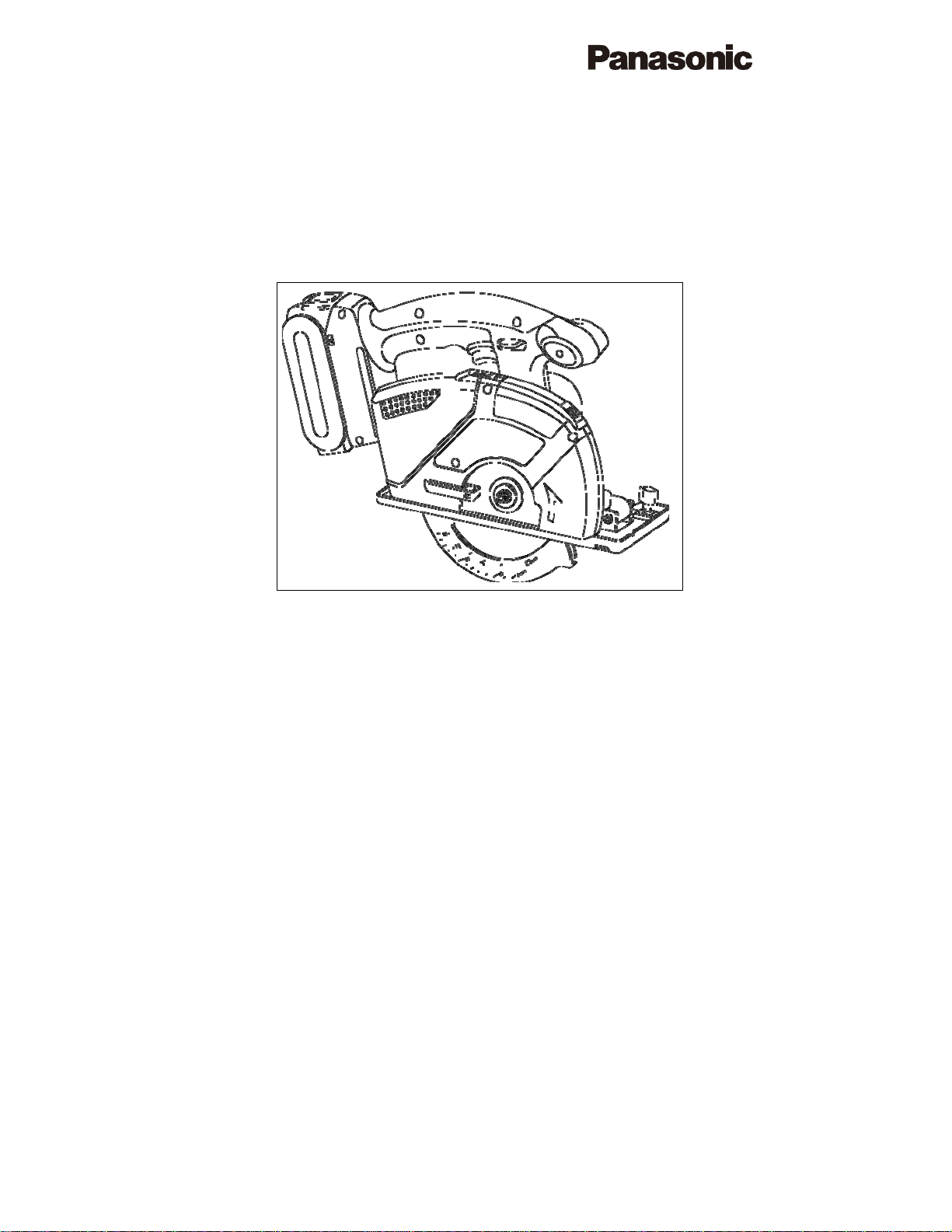
Cordless Multi Purpose Cutter
Akku-Mehrzwecksäge
Model No: EY4542
Before operating this unit, please read these instructions completely and save this manual for future use.
Vor Inbetriebnahme des Gerätes die Betriebsanleitung bitte gründlich durchlesen und diese Broschüre zum
späteren Nachschlagen sorgfältig aufbewahren.
- 1 -
Page 2
Index/Index
English: Page 4
Deutsch: Seite 21
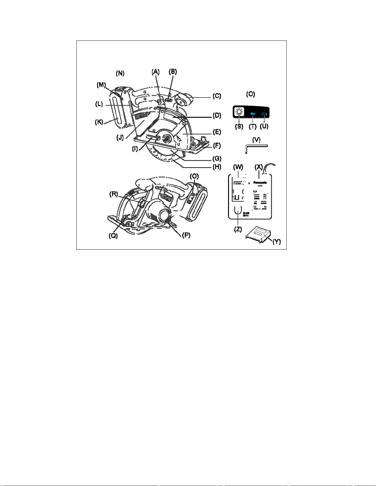
FUNCTIONAL DESCRIPTION
FUNKTIONSBESCHREIBUNG
Fig. 1
- 2 -
Page 3

A Power switch B Switch lock lever C Front grip
Betriebsschalter Schalter-Verriegelungshebel Vorderer Griff
D Front cover E Transparent guard F Shoe
Frontabdeckung Klarsichthaube Gleitschuh
G Blade (EY9PM13C) H Lower guard I Retracting handle
Blatt (EY9PM13C) Untere Schutzvorrichtung Rückzughebel
J Dust case K Battery pack (EY9L40) L Storage slot for hex wrench
Staubgehäuse Akkupack (EY9L40) Schlüsseldepot
M
Battery pack alignment mark
Akku-Ausrichtmarke
P Depth adjustment nut Q LED light R Spindle lock button
Tiefeneinstellmutter LED-Leuchte Spindelarretierknopf
S
LED light on/off button
LED-Leuchten-EIN/AUS-Taste
V Hex wrench W Li-ion battery pack dock X Battery charger (EY0L80)
Inbusschlüssel Li-Ion-Akkuladeschacht Ladegerät (EY0L80)
Y Pack cover Z
Akkuabdeckung
N Battery pack release button O Control panel
Akku-Entriegelungsknopf Bedienfeld
Overheat warning lamp
T
(battery)
Überhitzungs-Warnlampe
(Akku)
Ni-MH/Ni-Cd battery pack
dock
Ni-MH/Ni-Cd-Akkuladeschacht
U Battery low warning lamp
Akkuladungs-Warnlampe
- 3 -
Page 4

I. INTRODUCTION
This tool is a Multi Purpose Cutter. By changing
the blade, it can be used to cut wood, metal, and
plastic. Dust can be collected by an integrated
dust case or via a connected vacuum (by attaching the hose to the cutter).
DANGER
This product is a cutting tool, designed to cut
through metal and wood. It has a rotating blade
which is capable of cutting you deeply, causing
serious injury or death. As a result, please read
this manual and the cautionary markings on the
tool carefully, and obey all of the Safety Instructions to avoid such injury.
WARNING
To avoid injury, never insert your finger or any
other object into any opening of the tool.
WARNING
Read all safety warnings and all instructions.
Failure to follow the warnings and instructions
may result in electric shock, fire and/or serious
injury.
How to Use This Manual
• Please read this manual completely before
starting to cut with your tool. If you let someone
else use the tool, make sure they either read
this manual or are fully instructed in the proper
use and all safety precautions concerning the
tool.
• Please keep this manual for future reference. It
contains important safety information that you
must follow to use the tool safely.
• This manual and product use the following
signal words:
NOTE
Notes provide additional information that you
should know about the tool.
CAUTION
Caution indicates a potentially hazardous situation, which could result in minor or moderate
injury if not avoided. Cautions also alert you to
unsafe practices to be avoided.
WARNING
Warning indicates a potentially hazardous situation, which could result in serious injury or death
if not avoided.
DANGER
Danger indicates an imminent hazard which will
result in serious injury or death if not avoided.
Read “the Safety Instructions” booklet and
the following before using.
II. ADDITIONAL SAFETY
RULES
Safety instructions for all
saws
DANGER
1) Keep hands away from cutting area and the
blade. Keep your second hand on auxiliar y
handle, or motor housing. If both hands are
holding the saw, they cannot be cut by the
blade.
2) Do not reach underneath the workpiece.
The guard cannot protect you from the blade
below the workpiece.
3) A dju st the cutting depth to the t h i c kn e s s o f
the workpiece. Less than a full tooth of the
blade teeth should be visible below the workpiece.
4) Never hold piece being cut in your hands
or across your leg. Secure the workpiece to
a stable platform. It is important to support
the work properly to minimize body exposure,
blade binding, or loss of control.
5) Hold power tool by insulated gripping sur-
faces when performing an operation where
the cutting tool may contact hidden wiring
or its own c ord. Contact with a “live” wire will
also make exposed metal parts of the power
tool “live” and shock the operator.
6) When ripping always use a rip fence or
straight edge guide. This improves the accuracy of cut and reduces the chance of blade
binding.
7) Always use blades with correct size and
shape (diamond versus round) of arbour
holes. Blades that do not match the mounting
hardware of the saw will run eccentrically,
causing loss of control.
8) Never use damaged or incorrect blade
washers or bolt. The blade washers and bolt
were specially designed for your saw, for optimum performance and safety of operation.
- 4 -
Page 5

Further safety instructions for all saws
Causes and operator prevention of kickback:
- kickback is a sudden reaction to a pinched,
bound or misaligned saw blade, causing an
uncontrolled saw to lift up and out of the workpiece toward the operator;
- when the blade is pinched or bound tightly by
the kerf closing down, the blade stalls and the
motor reaction drives the unit rapidly back toward the operator;
- if the blade becomes twisted or misaligned in
the cut, the teeth at the back edge of the blade
can dig into the top surface of the wood causing the blade to climb out of the kerf and jump
back toward the operator.
Kickback is the result of saw misuse and/or incorrect operating procedures or conditions and
can be avoided by taking proper precautions as
given below.
1) Maintain a firm grip with both hands on the
saw and position your arms to resist kickback forces. Position your body to either
side of the blade, but no t in line with the
blade.
Kickback could cause the saw to jump backwards, but kickback forces can be controlled
by the operator, if proper precautions are
taken.
2) When blade is binding, or when interrupt-
ing a cut for any reason, rele as e the tri g ge r
and hold the saw motionless in the material
until the blade comes to a complete sto p.
Never attempt to remove the saw from the
work or pull the saw backward while the
blade is in motion or kickback may occur.
Investigate and take corrective actions to
eliminate the cause of blade binding.
3) When restarting a saw in the workpiece,
center the saw blade in the kerf and check
that saw teeth are not engaged into the
material.
If saw blade is binding, it may walk up or kickback from the workpiece as the saw is restarted.
4) Support large panels to minimize the risk of
blade pinching and kickback.
Large panels tend to sag under their own
weight. Supports must be placed under the
panel on both sides, near the line of cut and
near the edge of the panel.
5) Do not use dull or damaged blades.
Unsharpened or improperly set blades produce narrow kerf causing excessive friction,
blade binding and kickback.
6) Blade depth and bevel adjusting locking
levers must be tight and secure before
making cut.
If blade adjustment shifts while cutting, it may
cause binding and kickback.
7) Use extra caution when making a “ plunge
cut” into existing walls or other blind areas.
The protruding blade may cut objects that can
cause kickback.
Safety instructions for
this saw
1) Check lower guard for proper closing before each use. Do not operate the saw if
lower guard does not move freely and close
instantly. Never clamp or tie the lower guard
into the open position.
If saw is accidentally dropped, lower guard
may be bent. Raise the lower guard with the
retracting handle and make sure it moves
freely and does not touch the blade or any
other part, in all angles and depths of cut.
2) Check the operation of the lower guard
spring. If the guard and the spring are not
operating properly, they must be serviced
before use.
Lower guard may operate sluggishly due to
damaged parts, gummy deposits, or a build-up
of debris.
3) Lower guard should be retracted manually
only for special cuts such as “plunge cuts”
and “compound cuts.” Raise lower guard
by retracting handle and as soon as blade
enters the material, the low er guard must
be released.
For all other sawing, the lower guard should
operate automatically.
4) Always observe that the lower guard is
covering the blade before placing saw
down on bench or floor.
An unprotected, coasting blade will cause the
saw to walk backwards, cutting whatever is in
its path. Be aware of the time it takes for the
blade to stop after switch is released.
5) Do not use any abrasive wheels.
6) Wear a dust mask, if the work causes dust.
7) Use saw blades recommended by Manufacture.
8) Wear ear protectors when using the tool for
extended periods.
9) The risk of kickback increases as the battery pack discharges.
10) Be sure to inspect material. Avoid cutting
other different material.
11) Be careful not to drop the tool.
- 5 -
Page 6
12) Never swing the tool.
13) Never cover the ventilation slots, and keep
them free from dust or other material.
14) Do not clamp the tool in a vis e. Never cut
with the tool held upside down in a vise.
This is extremely dangerous and can lead
to serious accidents.
15) Never wear kn itted gloves.
16) Be sure no one is below when using the
tool in high locations.
17) Do not touch the blade immediately after
operation. It may be hot and could burn
your skin.
18) Do not touch material after it has been cut.
Cut material may be very hot.
19) Do not use cutting oil. Th is use of cutt ing oil
may cause a fire.
20) Do not cut workpieces covered or stained
with gas, oil, solvents, thinners, etc.
Exposure to these materials may damage
the transparent guard.
21) Do not remove the transparent and lower
guards. If the transparent and lower guards
is damaged or missing, return tool to authorized service center for replacement.
22) Do not start the blade when in contact with
workpiece. Wait for blade to reach full
speed before beginning cut.
Symbol
Symbol Meaning
V Volts
n
0
-1
··· min
A Amperes
Direct current
No load speed
Revolutions or reciprocations
WARNING
• Do not use other than the Panasonic battery
packs that are designed for use with this rechargeable tool.
• Do not dispose of the battery pack in a fire, or
expose it to excessive heat.
• Do not drive the likes of nails into the battery
pack, subject it to shocks, dismantle it, or attempt to modify it.
• Do not allow metal objects to touch the battery
pack terminals.
• Do not carry or store the battery pack in the
same container as nails or similar metal objects.
• Do not charge the battery pack in a
high-temperature location, such as next to a
fire or in direct sunlight. Otherwise, the battery
may overheat, catch fire, or explode.
• Never use other than the dedicated charger to
charge the battery pack. Otherwise, the battery may leak, overheat, or explode.
• After removing the battery pack from the tool
or the charger, always reattach the back
cover. Otherwise, the battery contacts could
be shorted, leading to a risk of fire.
III. ASSEMBLY
Attaching or Removing Battery
Pack
CAUTION:
Before inserting battery pack, check that the
power switch in the tool actuates properly and
returns to the “OFF” position when released.
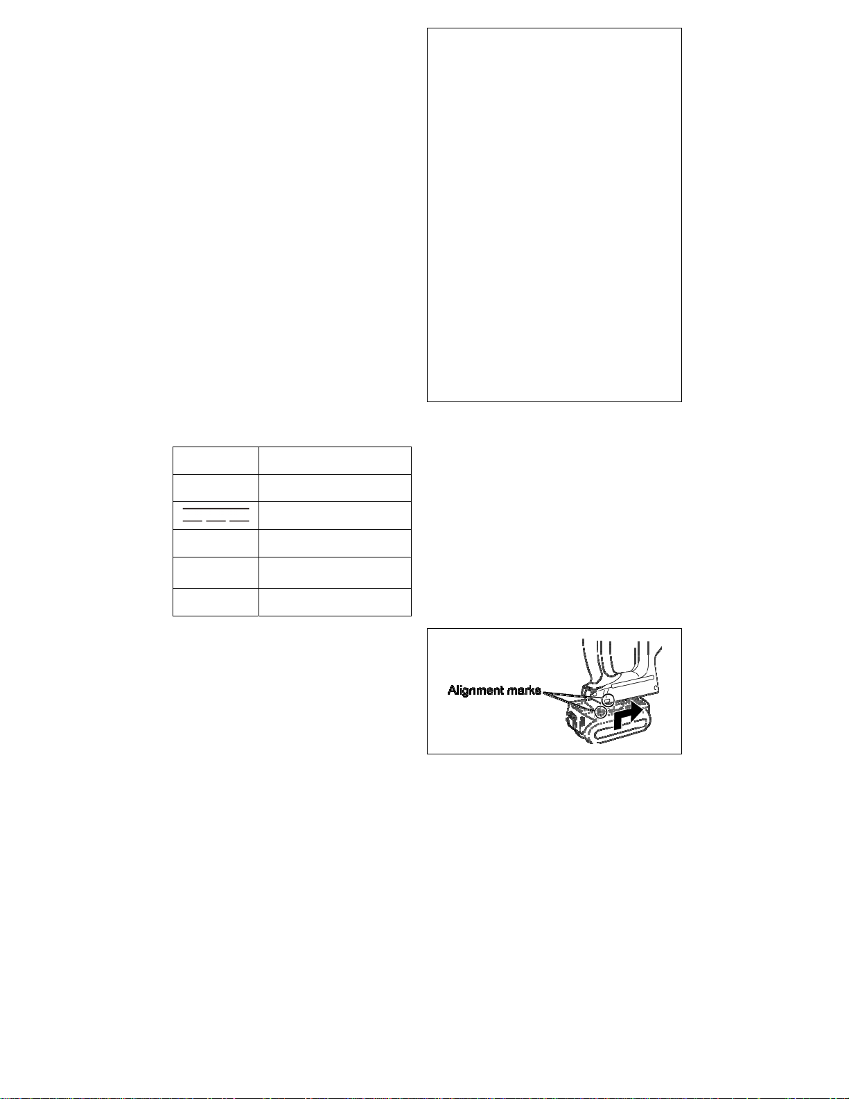
1. To connect the battery pack (See Fig. 2)
Line up the alignment marks and attach the
battery pack.
• Slide the battery pack until it locks into
position.
- 6 -
Fig. 2
Page 7
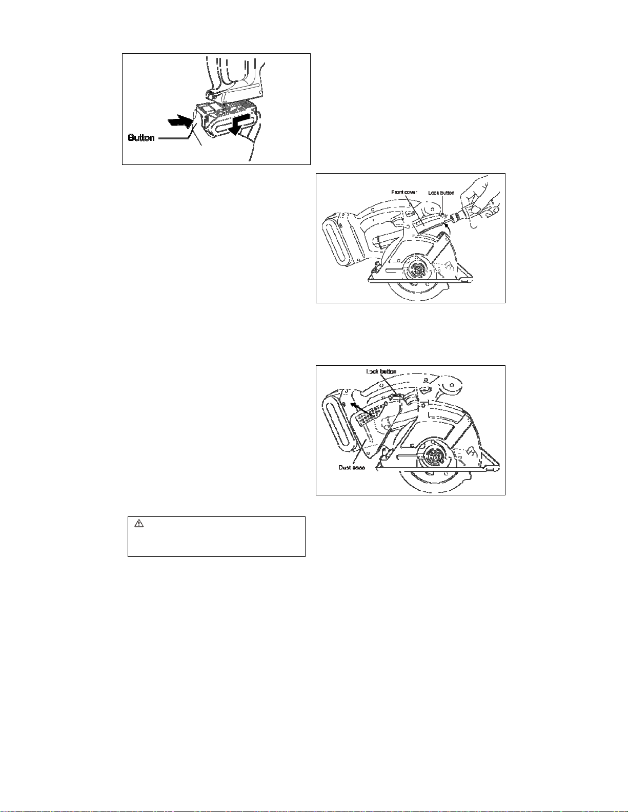
2. To remove the battery pack (See Fig. 3)
Push on the button from the front to release
the battery pack.
Fig. 3
IV. OPERATION
Before Using the Tool
This tool is intended for cutting unhardened ferrous metal, nonferrous metal, wood, and plastic.
Refer to the “Accessories” section for a list of
blades to be used for the proper applications of
this tool. The following precautions must be followed to reduce the risk of injury;
• Do not cut stacked materials. Cut one piece at
a time.
• Do not cut hardened steel.
• Cut materials with the wider edge of the shoe
over the clamped side of the material.
• Do not touch the saw blade, workpiece, or
cutting chips with bare hands immediately after
cutting; they may be hot and could burn skin.
Each time you use the tool, you must make sure
it is in good operating condition.
Use the following checklist:
1. Is the blade installed in the correct direction?
The arrow on the blade must point in the same
direction as the arrow on the upper blade cover.
2. Is the blade installed properly?
Make sure the hex bolt is tightened securely.
(See Fig. 6)
3. Does the blade look alright?
Replace the blade immediately if there are any
cracks in it or if any teeth are broken.
4. Does the lower guard close properly?
WARNING
To avoid injury, do not use the tool if the lower
guard does not close quickly over the blade.
6. Is the battery pack charged and inserted firmly
to the tool?
7. Is the depth adjustment nut for cutting securely
tightened?
8. Is the workpiece securely clamped on a saw
horse or bench?
9. Is the dust case or front cover clogged with
dust?
Disengage the front cover lock button and
remove any dust that has become clogged inside the cover. If the cover is clogged, use a
long object such as a manual screwdriver to
unclog it. After doing so, close the front cover.
(See Fig. 4)
Fig. 4
If there is dust inside the dust case, disengage
the dust case lock button, detach the dust case,
and remove the dust. After doing so, reattach
the dust case. (See Fig. 5)
Fig. 5
5. Is the transparent guard securely installed?
- 7 -
Page 8

Installing Blade
Follow these steps:
1. Remove the battery pack from the tool.
2. Remove any cutting debris from blade area.
3. Use the retracting handle to retract (open) the
lower guard.
4. Install the blade as illustrated. (See Fig. 6)
Make sure that both the direction arrow on the
blade and the direction arrow on the upper
blade cover point in the same direction.
5. Set the outer washer in place.
6. Insert the hex bolt.
7. Hold the spindle lock button down. This prevents the blade from rotating.
8. Tighten the hex bolt securely with the provided
hex wrench. Store the hex wrench.
NOTE:
Keep the hex wrench in the storage slot on the
cutter’s body when not using it.
WARNING
Failure to follow these instructions can result in
serious personal injury.
Removing Blade
CAUTION:
The blade will be hot right after cutting. Be sure
to let the blade cool down before removing it.
Follow these steps:
1. Remove the battery pack from the tool.
2. Hold the spindle lock button down. This prevents the blade from rotating.
3. Use the provided hex wrench to loosen the hex
bolt.
NOTE:
Keep the hex wrench in the storage slot on the
cutter’s body when not using it.
4. Remove the hex bolt and outer washer.
5. Use the retracting handle to retract (open) the
lower guard.
6. Carefully remove the blade.
7. Clean the tool if necessary.
CAUTION:
Be careful to avoid cutting your hands on the
blade.
• When disposing of a blade, secure it inside
heavy or corrugated paper. This will help
prevent anyone from being cut by the discarded blade.
Fig. 6
- 8 -
Page 9

Using the Tool
CAUTION:
To reduce the risk of injury read the Safety Instructions at the front of this manual before using
the tool.
WARNING
To reduce the risk of injury, wear safety goggles or glasses with side shields while using
the cutter. Additionally, wear a dust mask
when cutting materials that generate excessive particulate matter. Do not use cutter in
the rain. Doing so may result in electric shock
or cause the cutter to emit smoke.
Do not cut materials on which there is any
paint thinner, gasoline, oil, or similar build-up.
Doing so may cause the dust case to crack,
resulting in injury.
Follow these steps:
Hold the tool with both hands. (See Fig. 8) Do not
attempt to remove cut material when blade is
moving.
1. Line up the sight line on shoe with your cutting
line. (See Fig. 7)
Alignment with cutting line
• Position the notch on the shoe over the cutting
line, aligning the top and bottom corners of the
diamond-shaped opening with the line.
As the cutting position may differ depending on
the blade, do a trial cut beforehand.
Fig. 7
2. Press the switch lock lever down, then
squeeze the power switch to start the motor,
and then release the switch lock lever.
Fig. 8
CAUTION:
• Check that the switch lock lever works.
If power switch can be activated without de-
pressing the switch lock lever, discontinue use
immediately. Take the tool to an authorized
service center.
• Always hold the handle with one hand and the
front grip with the other. (See Fig. 8) Maintain a
firm grip and depress the switch fully.
• The blade should not touch the cutting material
before you start the motor. Wait until the blade
reaches full speed before starting a cut.
• This tool has no provision to lock the power
switch in the “ON” position, and you must not
attempt to secure it in the “ON” position.
3. Start cutting when the blade reaches full
speed.
4. During cutting, keep your cutting line straight.
Move the tool forward at a steady speed, while
looking at the tip of the blade through the
transparent guard.
WARNING
• To prevent dangerous kickback, keep the
shoe of the tool flat on the surface of the material being cut.
• Never force the tool. Use light and continuous
pressure.
5.If the motor starts to feel too warm, stop cutting.
Let the tool cool down before continuing work.
6. It is always a safe practice to remove the battery pack after use and before storing the tool.
Cutting depth adjustment
• Remove battery pack.
• Loosen the depth adjustment nut and adjust
the cutting depth, using the graduations on the
lower guard to gauge the depth. Once finished
adjusting the depth, tighten the depth adjust-
- 9 -
Page 10

ment nut securely.
* When wood material is 10 mm (3/8") or less
thick, adjust the cutting depth so that the blade
protrudes approx. 5 mm (3/16") from the bottom of the material.
Fig. 9
Rip fence (EY3500B7727)
(Available as an accessory, not included)
Rip fence is convenient for rip cuts and repeated
cuts of uniform width.
• Remove battery pack.
• Insert rip fence and adjust cutting width. (See
Fig. 10)
• Fasten screw securely to fix rip fence.
jury.
* When cutting metal materials, do not attach a
vacuum cleaner.
Sparks and hot metal chips may cause the
vacuum to be caught in fire. Operate the vacuum cleaner in accordance with its instructions.
(1) Collect dust in the dust case.
* Empty the dust case when it is filled up with
dust.
* Empty the dust case before storing the
cutter.
* Dust case capacity
• When cutting electrical conduit with a
diameter of 25 mm (1"), approximately xx
cuts
• When cutting 45 mm (25/32") x 45 mm
(25/32") lumber, approximately xx cuts
NOTE
The unique physical properties of some materials
may cause dust to become clogged inside the
front cover when cutting those materials.
Fig. 10
Collecting Dust
WARNING
* Before cutting metal materials, always empty
the dust case, open the front cover and remove
the dust.
• Use the cutter with the flammable materials in
the dust case to cut metal materials may result in fire.
* When cutting metal materials, always use the
cutter with the dust case attached.
• Flying sparks and metal chips may cause in-
Fig. 11
(2) Use with vacuum cleaner to collect dust.
* Connect the cutter to the hose using the
EY9X012E vacuum cleaner hose adapter
(sold separately).
Compatible hose inner diameter: 25 mm
(1") to 38 mm (2/1")
* Operate the vacuum cleaner obeying its in-
structions.
- 10 -
Page 11

Fig. 12
NOTE
When the cutter has difficulty ejecting or collecting dust.
The cutter outlet may be clogged with dust. Open
the front cover and remove any dust.
flashlight, since it does not have enough
brightness.
• Power automatically turns off immediately after
the battery pack is installed or when the LED
light is on and the driver has not been used for
5 minutes or more or when the LED light is
turned off and the driver has not been used for
1 minute or more. Please depress the switch to
operate the drill again.
This tool has the built-in LED light.
This tool is classified into “Class 1 LED Product”
to IEC (EN) 60825-1:2001.
Class 1 LED Product
Caution
Use of controls or adjustments or performance of
procedures other than those specified herein
may result in hazardous radiation exposure.
: DO NOT STARE INTO BEAM.
Control Panel
(1) LED light
Fig. 13
Pressing
the LED light on and off.
The light illuminates with
does not adversely affect the performance of the
tool during use or its battery capacity.
CAUTION:
• The built-in LED light is designed to illuminate
the small work area temporarily.
• Do not use it as a substitute for a regular
(LED light ON/OFF button) toggles
very low current, and it
(2) Overheat warning lamp
The overheating protection feature halts tool
operation to protect the battery pack in the
event of overheating. The overheat warning
lamp on the control panel flashes when this
feature is active.
• If the overheating protection feature activates, allow the tool to cool thoroughly (at
least 30 minutes). The tool is ready for use
when the overheat warning lamp goes out.
• Avoid using the tool in a way that causes
the overheating protection feature to activate repeatedly.
(3) Battery low warning lamp
Excessive (complete) discharging of lithium
- 11 -
Page 12

ion batteries shortens their service life dramatically. The tool includes a battery protection feature designed to prevent excessive
discharging of the battery pack.
• The battery protection feature activates
immediately before the battery loses its
charge, causing the battery low warning
lamp to flash.
• If you notice the battery low warning lamp
flashing, charge the battery pack immediately.
For Proper Use (Further Detail)
WARNING
To prevent the risk of serious personal injury:
It is important to use an appropriate device
to hold the material being cut properly, and
to hold the cutter firmly with both hands to
prevent loss of control which could cause
personal injury.
• Figure 14 shows proper cutting position.
• Note that hands are kept away from cutting
area.
• Make sure bystanders are away from work
area and from underneath of workpiece.
• When cutting, do not try to hold the material
with your hand.
Cutting large sheets;
Support large sheets. Be sure to set the
depth of the cut so that you only cut through
the workpiece, not through the supports.
(See Fig. 15)
Large sheets sag or bend if they are not correctly supported. If you attempt to cut without
levelling and properly supporting the workpiece, the blade will tend to bind, causing
kickback. (See Fig. 16)
• Don’t support the material away from the
cut.
Cutting thin or corrugated materials;
Cut thin and corrugated materials at least 1"
from the edge of the workpiece to avoid injury or damage to the tool caused by thin
strips of metal being pulled into the upper
guard.
•Use sharp blades only. Clean and sharp
blades minimize stalling and kickback.
Fig. 14
Fig. 15
Fig. 16
- 12 -
Page 13

WARNING
To prevent the risk of serious personal injury:
• When making an incomplete cut or cutting is interrupted, or blade is binding or cutter is stalling; release the power switch immediately and hold the cutter motionless in the material until the blade
comes to a complete stop.
• To avoid kickback, never attempt to remove the cutter from the work or pull the cutter backward while
the blade is in motion. Make sure the blade has come to a complete stop, then remove cutter from
cut.
• To resume cutting, start cutter, allow the blade to reach full speed, reenter the cut slowly and resume
cutting.
1. Place the wider part of the shoe on the part of the work piece which is solidly supported (See Fig. 17),
never on the section that will fall off when the cut is made. (See Fig. 18)
Hold the cutter firmly to prevent loss of control. Working carelessly can cause severe personal injury.
Fig. 17 Fig. 18
2. Make sure the blade stops.
Even though your tool has a brake, before setting the tool down, make sure the blade has come to a
complete stop and the lower guard has closed.
3. Do not use if anything seem unusual. Remove battery pack immediately.
If the tool body becomes very hot, or does not work properly, remove the battery pack and do not use.
Have it checked by an authorized service center.
WARNING
To prevent the risk of serious personal injury or fire, do not try to repair the tool by yourself. Never
disassemble or modify the tool body. There are no user-repairable parts inside.
4. NEVER ALLOW THE CUTTER TO COME IN CONTACT WITH YOUR BODY.
After completing a cut, do not allow the cutter to brush against your leg or side.
Since the lower guard is retractable, it could catch on your clothing and expose the blade. Keep
clothing away from tool. Be aware of the exposed blade sections that exist in both the upper and
lower guard areas.
WARNING
Because cutting metal creates sparks;
• Always use safety goggles.
• Do not use tool near any flammable substance or in an area where flammable substances are used.
Fire and burn injury could result.
5. Never engage the spindle lock while blade is running, or engage in an effort to stop the tool. Never
turn the switch on when the spindle lock is engaged. Serious damage to your tool will result.
- 13 -
Page 14

[Battery Pack]
For Appropriate Use of
Battery pack
Li-ion Battery pack (EY9L40)
• For optimum battery life, store the Li-ion bat-
tery pack following use without charging it.
• When charging the battery pack, confirm that
the terminals on the battery charger are free of
foreign substances such as dust and water etc.
Clean the terminals before charging the battery
pack if any foreign substances are found on
the terminals.
The life of the battery pack terminals may be
affected by foreign substances such as dust
and water etc. during operation.
• When battery pack is not in use, keep it away
from other metal objects like: paper clips, coins,
keys, nails, screws, or other small metal objects that can make a connection from one
terminal to another.
Shorting the battery terminals together may
cause sparks, burns or a fire.
• When operating the battery pack, make sure
the work place is well ventilated.
• When the battery pack is removed from the
main body of the tool, replace the battery pack
cover immediately in order to prevent dust or
dirt from contaminating the battery terminals
and causing a short circuit.
[Battery Charger]
Charging
Cautions for the Li-ion Battery
Pack
• If the temperature of the battery pack falls
approximately below −10°C (14°F), charging
will automatically stop to prevent degradation
of the battery.
Common Cautions for the Liion/Ni-MH/Ni-Cd Battery Pack
• The ambient temperature range is between
0°C (32°F) and 40°C (104°F).
If the battery pack is used when the battery
temperature is below 0°C (32°F), the tool may
fail to function properly.
• When charging a cool battery pack (below 0°C
(32°F)) in a warm place, leave the battery pack
at the place and wait for more than one hour to
warm up the battery to the level of the ambient
temperature.
•
Cool down the charger when charging more than
two battery packs consecutively.
• Do not insert your fingers into contact hole,
when holding charger or any other occasions.
CAUTION:
To prevent the risk of fire or damage to the battery charger.
• Do not use power source from an engine gen-
• Do not cover vent holes on the charger and the
• Unplug the charger when not in use.
erator.
battery pack.
Battery Pack Life
The rechargeable batteries have a limited life. If
the operation time becomes extremely short after
recharging, replace the battery pack with a new
one.
Battery Recycling
ATTENTION:
For environmental protection and recycling of
materials, be sure that it is disposed of at an
officially assigned location, if there is one in your
country.
Li-ion Battery Pack
NOTE:
Your battery pack is not fully charged at the time
of purchase. Be sure to charge the battery before
use.
Battery charger (EY0L80)
1. Plug the charger into the AC outlet.
NOTE:
Sparks may be produced when the plug is inserted into the AC power supply, but this is not
a problem in terms of safety.
2.
Insert the battery pack firmly into the charger.
1. Line up the alignment marks and place the
battery onto the dock on the charger.
2. Slide forward in the direction of the arrow.
- 14 -
Page 15

During charging, the charging lamp will be lit.
3.
When charging is completed, an internal elec-
tronic switch will automatically be triggered to
prevent overcharging.
• Charging will not start if the battery pack is
warm (for example, immediately after
heavy-duty operation).
The orange standby lamp will be flashing un-
til the battery cools down.
Charging will then begin automatically.
4. The charge lamp (green) will flash slowly once
the battery is approximately 80% charged.
5. When charging is completed, the charging lamp
will start flashing quickly in green color.
6. If the temperature of the battery pack is 0°C or
less, charging takes longer to fully charge the
battery pack than the standard charging time.
Even when the battery is fully charged, it will
have approximately 50% of the power of a fully
charged battery at normal operating temperature.
7.
If the power lamp does not light immediately
after the charger is plugged in, or if after the
standard charging time the charging lamp does
not flash quickly in green, consult an authorized
dealer.
8. If a fully charged battery pack is inserted into
the charger again, the charging lamp lights up.
After several minutes, the charging lamp may
flash quickly to indicate the charging is completed.
Ni-MH/Ni-Cd Battery Pack
NOTE:
When you charge the battery pack for the first
time, or after prolonged storage, charge it for
about 24 hours to bring the battery up to full
capacity.
Battery charger (EY0L80)
1. Plug the charger into the AC outlet.
NOTE:
Sparks may be produced when the plug is inserted into the AC power supply, but this is not
a problem in terms of safety.
2.
Insert the battery pack firmly into the charger.
3. During charging, the charging lamp will be lit.
When charging is completed, an internal elec-
tronic switch will automatically be triggered to
prevent overcharging.
• Charging will not start if the battery pack is
warm (for example, immediately after
heavy-duty operation).
The orange standby lamp will be flashing un-
til the battery cools down. Charging will then
begin automatically.
4.
When charging is completed, the charging lamp
will start flashing quickly in green color.
5.
If the charging lamp does not light immediately
after the charger is plugged in, or if after the
standard charging time the charging lamp does
not flash quickly in green, consult an authorized
dealer.
6. If a fully charged battery pack is inserted into
the charger again, the charging lamp lights up.
After several minutes, the charging lamp may
flash quickly to indicate the charging is completed.
- 15 -
Page 16

LAMP INDICATIONS
Green Lit
Information for Users on Collection and Disposal of Old Equipment and used Batteries
These symbols on the products, packaging, and/or accompanying docu-ments mean
that used electrical and electronic products and batteries should not be mixed with
general household waste.
For proper treatment, recovery and recycling of old products and used bat-teries,
please take them to applicable collection points, in accordance with your national
legislation and the Directives 2002/96/EC and 2006/66/EC.
By disposing of these products and batteries correctly, you will help to save valuable
resources and prevent any potential negative effects on human health and the environment which could otherwise arise from inap-propriate waste handling.
For more information about collection and recycling of old products and bat-teries,
please contact your local municipality, your waste disposal service or the point of sale
where you purchased the items.
Penalties may be applicable for incorrect disposal of this waste, in ac-cordance with
national legislation.
Charger is plugged into the AC outlet.
Ready to charge.
Green Flashing Quickly
Charging is completed. (Full charge.)
Green Flashing
Battery is approximately 80% charged. (Usable charge. Li-ion only.)
Green Lit
Now charging.
Orange Lit
Battery pack is cool.
The battery pack is being charged slowly to reduce the load on the battery. (Li-ion only.)
Orange Flashing
Battery pack is warm. Charging will begin when temperature of battery pack drops.
If the temperature of the battery pack is –10°C or less, the charging status lamp (orange)
will also start flashing. Charging will begin when the temperature of the battery pack goes
up (Li-ion only).
Charging Status Lamp
Left: green Right: orange will be displayed.
Both Orange and Green Flashing Quickly
Charging is not possible. Clogged with dust or malfunction of the battery pack.
For business users in the European Union
If you wish to discard electrical and electronic equipment, please contact your dealer or supplier for
further information.
[Information on Disposal in other Countries outside the European Union]
These symbols are only valid in the European Union. If you wish to discard these items, please contact your local authorities or dealer and ask for the correct method of disposal.
Note for the battery symbol (bottom two symbol examples):
This symbol might be used in combination with a chemical symbol. In this case it complies with the
requirement set by the Directive for the chemical involved.
- 16 -
Page 17

V. MAINTENANCE
. ACCESSORIES
VI
WARNING
To avoid severe personal injury, always remove
the battery pack from the tool before starting any
maintenance procedure.
CAUTION:
To assure product SAFETY and RELIABILITY,
servicing should be performed by an authorized
service center. Always insist on genuine
Panasonic replacement parts.
Cleaning Tool
Keep your tool clean for good cutting performance, and to help keep it safe to use.
Follow these steps:
1. Remove the battery pack from the tool.
2. Wipe the tool with a dry, soft cloth. Do not
use a wet cloth or cleaning liquids.
They could damage the cutter’s finish.
3. Be sure to rub off any oil or grease which
could make the tool slippery or hard to handle.
4. Remove the blade and brush off any dust.
CAUTION:
To avoid injury or damage to the unit, never immerse any part of the tool in a liquid.
Transparent Guard
WARNING
If the guard is cracked, or is broken, take the tool
to an authorized service center for replacement.
Do not attempt to operate cutter. It could result in
serious personal injury.
Never use your tool with a damaged transparent
guard or without the transparent guard installed.
Flying chips could result in serious injury.
WARNING
• The use of any accessories not specified in
this manual may result in fire, electric shock,
or personal injury. Use recommended accessories only.
• Use of a blade on material that is thicker or
thinner than that recommended for that
blade will result in a rough cut, and could
increase the risk of “kickback
jury.
Carbide-tipped Blade for Metal
• EY9PM13C
For cutting unhardened ferrous material
Carbide-tipped Blade for Thin Metal (Optional
accessory)
• EY9PM13D
For cutting unhardened thin ferrous material
Carbide-tipped Blade for Wood (Optional ac-
cessory)
• EY9PW13A
For cutting wood
Carbide-tipped Blade for Thin Wood (Optional
accessory)
• EY9PW13B
For cutting thin wood
Carbide-tipped Blade for Plastic (Optional ac-
cessory)
• EY9PP13B
For cutting plastic material
Vacuum hose adaptor (Optional accessory)
• EY9X012E
Rip Fence (Optional accessory)
• EY3500B7727
For convenience of rip cuts and repeated cut
of uniform width
” or other in-
- 17 -
Page 18

VII. SPECIFICATIONS
Motor voltage 14.4 V DC
Blade speed XX min-1 (rpm)
Blade size
Outside diameter
Arbor size
Maximum cutting depth 0 – 46 mm (0" – 1-13/16") (φ 165 mm blade)
Overall length 329 mm (12-61/64")
Weight (with battery pack) 2.6 kg (5.7 lbs)
135 mm (5-5/16")
BATTERY PACK
Model EY9L40
Storage battery Li-ion Battery
Battery voltage 14.4 V DC (3.6 V × 4 cells)
Capacity 3 Ah
BATTERY CHARGER
Model EY0L80
Electrical rating See the rating plate on the bottom of the charger.
Weight 0.95 kg (2.1 lbs)
20 mm (25/32")
[Li-ion battery pack]
Charging
time
3 Ah
14.4 V 21.6 V 28.8 V
EY9L40
Usable: 35 min.
Full: 50 min.
Usable: 45 min.
- 18 -
EY9L60
Full: 60 min.
EY9L80
Usable: 55 min.
Full: 70 min.
Page 19

[Ni-Cd/Ni-MH battery pack]
7.2 V 9.6 V 12 V 15.6 V 18 V 24 V
EY9065
1.2 Ah
1.7 Ah
Charging
time
2 Ah
3 Ah
3.5 Ah
NOTE: This chart may include models that are not available in your area.
Please refer to the latest general catalogue.
EY9066
EY9168 EY9188
EY9080
EY9086
20 min.
EY9180
EY9182
EY9001
EY9101
EY9103
25 min.
30 min. 60 min.
EY9106
EY9107
EY9108
EY9200 EY9230 EY9210
EY9201 EY9231 EY9251
55 min.
EY9136
45 min. 90 min.
65 min.
EY9116
EY9117
- 19 -
Page 20

ONLY FOR U.K.
VIII. ELECTRICAL PLUG
INFORMA TION
FOR YOUR SAFETY PLEASE READ
THE FOLLOWING TEXT CAREFULLY
This appliance is supplied with a moulded three
pin mains plug for your safety and convenience.
A 5 amp fuse is fitted in this plug.
Should the fuse need to be replaced please
ensure that the replacement fuse has a rating
of 5 amp and that it is approved by ASTA or BSI
to BS1362.
Check for the ASTA mark
on the body of the fuse.
If the plug contains a removable fuse cover you
must ensure that it is refitted when the fuse is
replaced.
If you lose the fuse cover the plug must not be
used until a replacement cover is obtained.
A replacement fuse cover can be purchased
from your local Panasonic Dealer.
IF THE FITTED MOULDED PLUG IS UNSUITABLE FOR THE SOCKET OUTLET IN
YOUR HOME THEN THE FUSE SHOULD BE
REMOVED AND THE PLUG CUT OFF AND
DISPOSED OF SAFELY.
THERE IS A DANGER OF SEVERE ELECTRICAL SHOCK IF THE CUT OFF PLUG IS
INSERTED INTO ANY 13 AMP SOCKET.
If a new plug is to be fitted please observe the
wiring code as shown below.
If in any doubt please consult a qualified electrician.
or the BSI mark
IMPORTANT:
The wires in this mains lead are coloured
in accordance with the following code:
Blue: Neutral
Brown: Live
As the colours of the wire in the mains lead of
this appliance may not correspond with the
coloured markings identifying the terminals in
your plug, proceed as follows.
The wire which is coloured BLUE must be
connected to the terminal in the plug which is
marked with the letter N or coloured BLACK.
The wire which is coloured BROWN must be
connected to the terminal in the plug which is
marked with the letter L or coloured RED.
Under no circumstances should either of these
wires be connected to the earth terminal of the
three pin plug, marked with the letter E or the
Earth Symbol
How to replace the fuse: Open the fuse
compartment with a screwdriver and replace
the fuse and fuse cover if it is removable.
- 20 -
.
Page 21

Panasonic Electric Works Co., Ltd.
EN. GR. FR. IT. ND. ES. DN. SW. NR. FN. RUS. Uk
EY971045421 H2007 Printed in China
1048, Kadoma, Osaka 571-8686, Japan
- 21 -
Page 22

- 22 -
 Loading...