

Page 1
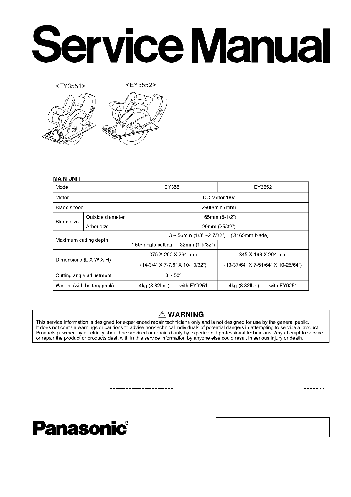
SPECIFICATIONS
ORDER NO.P T D0501U30C1
F16
Cordless Wood Saw / Cordless Metal Cutter
EY3551-U1
EY3552-U1
CONTENTS
Page Page
1 SCHEMATIC DIAGRAM 2
2 WIRING CONNECTION DIAGRAM
3 DISASSEMBLY INSTRUCTIONS
4 ASSEMBLY INSTRUCTIONS 7
2
5 TROUBLESHOOTING GUIDE
3
6 EXPLODED VIEW & REPLACEMENT PARTS LIST
© 2005 Matsushita Electric Works Ltd. All rights
reserved. Unauthorized copying and distribution is a
violation of law.
12
14
Page 2
EY3551-U1 / EY3552-U1
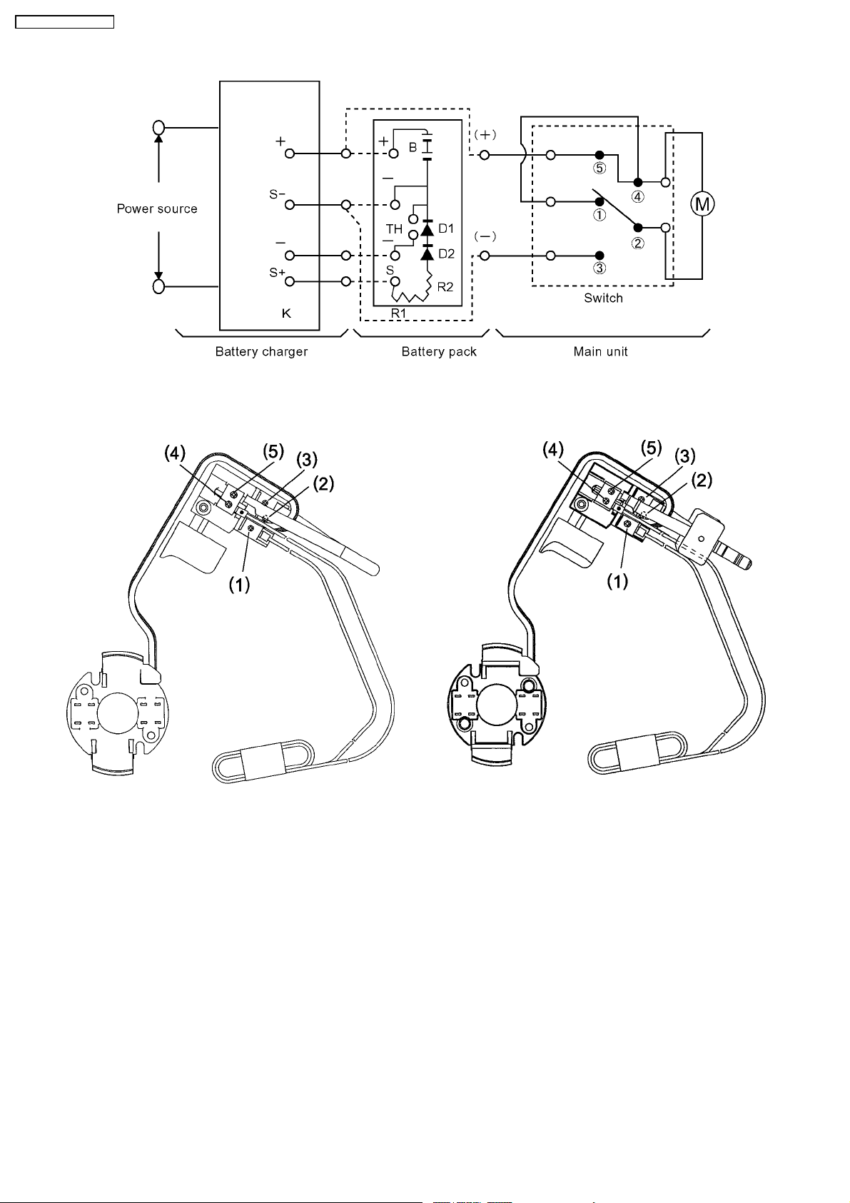
1 SCHEMATIC DIAGRAM
2 WIRING CONNECTION DIAGRAM
<EY3551> <EY3552>
2
Page 3
3 DISASSEMBLY INSTRUCTIONS
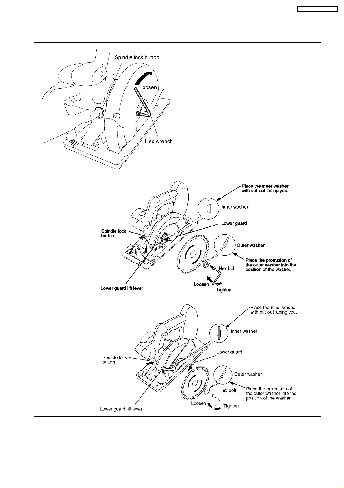
■BLADE REMOVAL.
Ref. No. 1A Procedure 1A Blade removal.
NOTE :
Make sure that the battery pack is removed from the saw prior
to servicing.
The blade will be hot right after cutting. Be sure to let the blade
cool down before removing it.
1. Hold the spindle lock button down. This prevents the blade from
rotating.
2. Use the provided hex wrench to loosen the hex bolt.
NOTE :
Keep the hex wrench in the storage slot on the body when not
using it.
3. Remove the hex bolt and outer washer.
4. Use the lower guard lift lever to open the lower guard.
5. Carefully remove the blade.
CAUTION:
Be careful to avoid cutting your hands on the blade.
EY3551-U1 / EY3552-U1
<EY3551>
<EY3552>
3
Page 4
EY3551-U1 / EY3552-U1
■MAIN UNIT DISASSEMBLY. (The main unit can be opened without removing the shoe.)
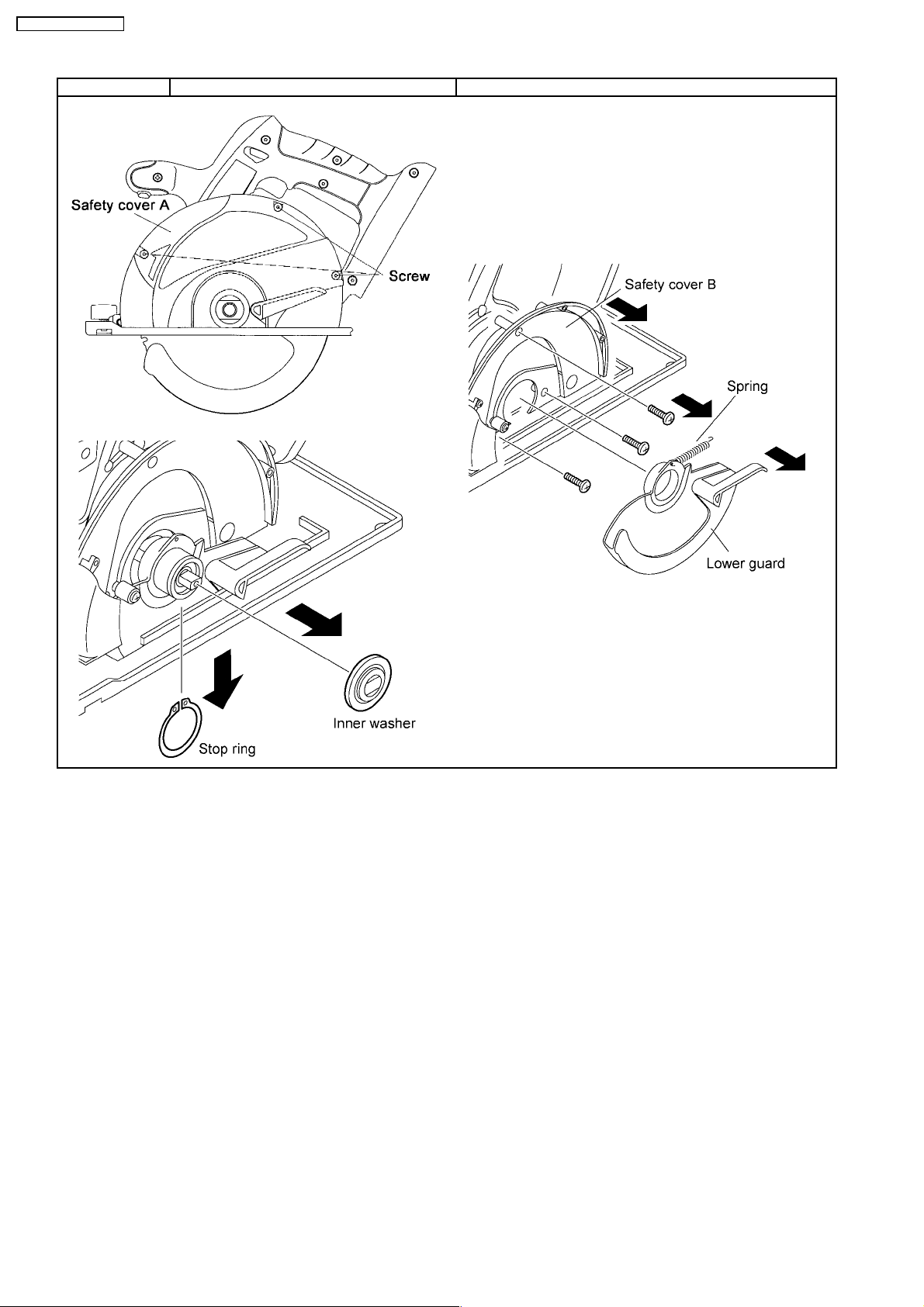
Ref. No. 2A Procedure 2A Removal of the safety cover and lower guard.
1. Loosen the base depth adjustment lever where located under the
grip of main unit and push the shoe down.
2. Remove the 3 screws securing the safety cover A. Take out the
safety cover A.
3. Remove the inner washer and the stop ring.
4. Remove the lower guard with connecting the spring.
5. Loosen the 3 screws and take out the safety cover B.
NOTE :
When removing the lower guard from the main unit, do not
stretch the spring.
4
Page 5
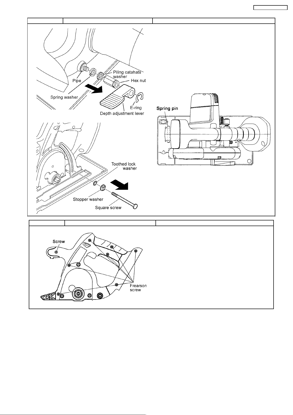
Ref. No. 2B Procedure 2A →→→→ 2B Removal of the shoe.
NOTE:
It is possible to disassemble the main unit without removing the
shoe.
1. Take out the E-ring and the depth adjustment lever.
2. Unscrew the hex nut.
3. Take out the spring washer and piling catahats washer.
4. Pull out the square screw and pipe.
5. Take out the stopper washer and toothed lock washer.
6. Push out the spring pin with a rod having a diameter of 5mm.
NOTE:
Do not tap the spring pin strongly. If to do so, the supporting
metal plates on both side of housing may cause the deformation.
EY3551-U1 / EY3552-U1
Ref. No. 2C Procedure 2A →→→→ 2C Removal of the Housing.
1. Loosen 7 housing screws (frearson type) and 1 (+) head screw.
It is then possible to disassembly the main unit or to check the
switch block and motor.
5
Page 6
EY3551-U1 / EY3552-U1
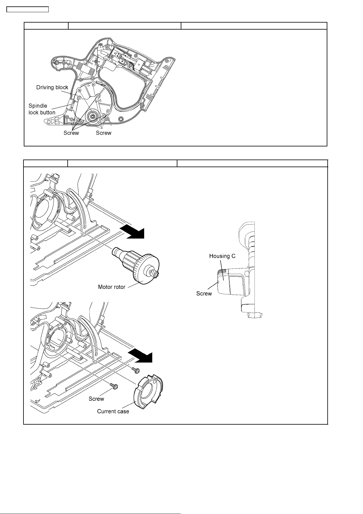
Ref. No. 2D Procedure 2A →→→→ 2C →→→→ 2D Removal of the gear box block.
1. Loosen the 4 screws where securing the driving block with the
housing in order to take out the gear box block from the main unit.
2. Remove the 4 screws and carefully open the gear box housing.
NOTE:
The internal parts of gear box block can be removed one after
another.
NOTE:
The spring of spindle lock button may pop out.
Ref. No. 2E Procedure 2A →→→→ 2C →→→→ 2D →→→→ 2E Assembly of the motor assembly.
1. Take out the motor rotor assembly from the motor stator.
2. Take out the current case.
3. Remove the 2 screws fastening the motor stator.
4. Take out the stator.
5. Take out the motor brush and switch assembly connected with
lead wires.
NOTE:
Loosen the 2 housing screws and take the housing C out for reassembling purpose.
6
Page 7

EY3551-U1 / EY3552-U1
4 ASSEMBLY INSTRUCTIONS
CAUTION:
The proper operatio n of the “off lock lever” is critical for the safe use and operation of the saw/cutter. Be extra careful in reassembling the unit and ensure that the “off lock lever” is properly positioned. Verify the operation of the “off lock lever” upon
completing the re-assembly procedure. Ensure that the power switch can only be activated after depressing the “off lock lever”.
■ MAIN UNIT ASSEMBLY.
Ref. No. 3A Procedure 3A Assembly of the motor assembly.
1. Hitch the brush spring to the frame by something like forceps.
2. Set the motor brush assembly into the housing.
NOTE:
Make sure that the white and black lead wire are set on upper
right position.
3. Put the motor brush in the case by sliding the lead wires outside on
both sides.
4. Set the motor stator.
NOTE:
The motor stator has its own proper direction for assembly. Make
sure to align the cut with the housing rib on both right and left
side.
5. Tighten the 2 screws.
NOTE:
Make sure that the both screws may bite the motor stator on both
sides slightly.
6. Set the current plate into the housing.
NOTE:
Make sure of the position of lead wires to prevent pinching.
7. Insert the motor rotor and lightly tapping it to set firmly.
7
Page 8

EY3551-U1 / EY3552-U1
Ref. No. 3B Procedure 3A →→→→ 3B Assembly of the spindle lock button and gear box.
1. Push and hold the spindle lock button while inserting the gearbox
block.
NOTE:
Confirm the direction of the spindle lock button. Place D-cut on
top.
In case of the spindle lock button hardly insert into the gearbox
block, rotate the shaft of gearbox slowly by hand.
Make sure that the spring is set in the circule properly.
2. Tighten the 4 screws crossing.
NOTE:
Make sure to align the triangle mark of the gearbox with the
housing.
Ref. No. 3C Procedure 3A →→→→ 3B →→→→ 3C Assembly of the switch.
1. Wiring the thin white lead wire and the black motor lead wire on
the proper positions.
2. Attach the battery terminals.
3. Wiring the white motor lead wire together with the thin white lead
wire.
4. Place the white lead wires (for braking) passes through between
the black and white motor lead wires.
5. Press fit the thin white lead wire (for braking) between screw
bosses firmly.
NOTE:
Be certain the lead wires are mounted in the proper position.
Make sure that they are not set on the screw bosses or over the
housing ribs.
8
Page 9

Ref. No. 3D Procedure 3A →→→→ 3B →→→→ 3C →→→→ 3D Assembly of the off lock lever.
1. Put the off lock lever into the housing boss.
2. Insert the one side of lever spring into the groove of the off lock
lever. And Hitch the other side of lever spring on the housing rib.
3. Greasing (Shell Alvania) on top of pin and insert it into housing
boss.
Ref. No. 3E Procedure 3A →→→→ 3B →→→→ 3C →→→→ 3D →→→→ 3E Assembly of the housing.
1. Tighten the 7 frearson housing screws and 1 (+) head screw.
NOTE:
Before closing the housing A and B, make sure that the O-ring is
set properly.
Make sure if battery terminals are set on housings.
EY3551-U1 / EY3552-U1
9
Page 10

EY3551-U1 / EY3552-U1
Ref. No. 3F Procedure 3A →→→→ 3B →→→→ 3C →→→→ 3D →→→→ 3E →→→→ 3F Assembly of the shoe.
1. Insert the spring pin with a rod having a diameter of 5mm.
NOTE:
Make sure that the slit part of spring is placed downward. And
protrusion of spring pin should be uniform on both side.
2. Place the toothed lock washer inside and the stopper washer to
the housing B.
3. Sliding the depth adjustment plate up with placing the stopper
washer into the ditch of the depth adjustment plate.
4. Pass the square screw through.
5. Insert the pipe and place the spring wahser and piling catahats
washer from housing A side with holding the square screw by hand.
6. Insert the hex nut and the shoe up (parallel to the main body).
7. Tighten the hex nut with the depth adjustment lever at 30kgfcm.
8. Set the depth adjustment lever.
NOTE:
Make sure that the depth adjustment lever is set about 14mm
away from housing. If the gap between housing and lever is less
than 14mm, take the lever out and turn 30degree toward your
side and try to set again.
9. Attach the NEW E-ring with pliers.
NOTE:
Please use the new E-ring every time disassembling the depth
adjustment lever assembly.
10
Page 11

Ref. No. 3G Procedure 3A →→→→ 3B →→→→ 3C →→→→ 3D →→→→ 3E →→→→ 3F
→→→→ 3G
EY3551-U1 / EY3552-U1
Assembly of the blade guard assembly.
1. Set the safty cover B with connecting the transparent guard and
tighten the 3 screws. (EY3552)
2. Hang the one side of spring (without marking side) on the safety
cover B.
3. Lightly greasing (ALVANIA) around the internal diameter and the
external diameter on the rear side of the lower guard.
4. Hang the other side of spring on the lower guard and set it to the
main unit.
5. Set the stop ring.
NOTE:
The stop ring has its own direction for assembly. Make sure that
the rounded side faces housing.
And make sure that 2 holes of stop ring should be placed upper
right.
6. Set the safety cover A and tighten the 3 screws with 25kgfcm.
7. Set the inner washer and carefully set the blade.
8. Set the outer washer and tighten the hex bolt using the provided
hex wrench with holding the spindle lock button.
Ref. No. 3H Procedure 3A →→→→ 3B →→→→ 3C →→→→ 3D →→→→ 3E →→→→ 3F
→→→→ 3G →→→→ 3H
11
Assembly of the motor housing.
1. Return the brush spring into the groove of the motor brush on
both sides.
2. Attach the housing C and tighten the 2 screws with 15kgfcm.
Page 12

EY3551-U1 / EY3552-U1
5 TROUBLESHOOTING GUIDE
(Refer to WIRING CONNECTION DIAGRAM)
12
Page 13

EY3551-U1 / EY3552-U1
13
Page 14

EY3551-U1 / EY3552-U1
6 EXPLODED VIEW & REPLACEMENT PARTS LIST
6.1. EXPLODED VIEW for EY3551
14
Page 15

6.2. REPLACEMENT PARTS LIST for EY3551
NOTE:
*B=only available as set
*C=available individually
Ref.No. Part No. Part Name & Description Remarks Per Unit
1 EY3500K0357 SPRING PIN 6-45 1
2 WEY3551S3428 BASE 1
3 EY3503K6487 ADJUSTING BOLT *C M5*10 2
4 EY3503K0197 SPRING 7.6*15 1
5 WEY3552S6388 SPRING WASHER *C 5 2
6 WEY3551S6398 PLAIN WASHER 5 1
7 WEY3552K6648 TOOTHED LOCK WASHER *C 2
8 WEY3552S6258 FLANGE SOCKET M5*12 1
9 WEY3552K1178 OUTER WASHER 1
10 WEY3552K6208 ALUMINUM TIGHT SCREW *C 4*16 3
11 WEY3551S3108 SAFETY COVER A 1
12 WEY3552L1168 INNER WASHER 1
13 EY3503L0427 STOP RING 1
14 WEY3551Y1198 LOWER GUARD 1
15 WEY3552L0928 SPRING 5.9*49 1
16 WEY3552K0398 LOWER GUARD STOPPER 1
17 WEY3551S3118 SAFETY COVER B 1
18 WEY3503L6537 SQUARE SCREW 1
19 WEY3552S6688 STOPPER WASHER 1
20 WEY3552L0078 PIPE 8 1
21 WEY3552K6698 PILING CATAHATS WASHER 1
22 WEY3552S6348 DEPTH ADJUSTING NUT 1
23 WEY3552Y0897 DEPTH ADJUSTMENT LEVER 1
24 WEY3552S0168 E RING 1
25 EY3503K6208 FREARSON SCREW *C K4*20 20
26 WEY3552K9078 TAPPING SCREW K4*25 1
27 EY3530L0977 O RING 1
28 WEY3551K3078 HOUSING AB SET 1
29 WEY3551K3088 HOUSING C 1
30 WEY3552Y0368 SPINDLE LOCK BUTTON 1
31 WEY3552L0168 LOCK BUTTON SPRING 16.6*19.8 1
32 WEYT502Y1587 OFF LOCK LEVER 1
33 WEYT502L0917 OFF LOCK SPRING 1
34 WEY3552L0508 PIN 1.5 1
35 WEY3552L1458 GEAR BOX ASSEMBLY 1
36 WEY3552L1768 GEAR BOX 1
37 EY3503L0847 THRUST PLATE *C 2
38 WEY3552L1438 MID GEAR 1
39 WEY3552L1468 MOTOR ROTOR ASSEMBLY 1
40 WEY3552L0448 CURRENT PLATE 1
41 WEY3552S9038 P TIGHT SCREW *B K3*20(2PCS/PK) 2
42 WEY3552L1188 STATOR 1
43 WEY3552L2308 BRUSH ASSEMBLY 1
44 WEY3551Y2008 SWITCH 1
45 WEY3551S0068 BATTERY CONTACTS 1
46 EY6230L0207 DUST PREVENTIVE PLATE 1
47 WEY3552K7868 HEX WRENCH 1
48 WEY3551S6298 SET SCREW 1
- WEY3552K7018 TOOL CASE 1
- WEY3551K8008 INDIVIDUAL BOX 1
- WEY3551K8108 OPERATING INSTRUCTIONS 1
EY3551-U1 / EY3552-U1
**Battery Pack, and Tool Case are available as an optional accessory.
See the nearest sales dealer for details.
***For replacement parts of charger, see the charger service manual.
Charger complete set is available as an optional accessory. See the nearest sales dealer for details.
15
Page 16

EY3551-U1 / EY3552-U1
6.3. EXPLODED VIEW for EY3552
16
Page 17

6.4. REPLACEMENT PARTS LIST for EY3552
NOTE:
*B=only available as set
*C=available individually
Ref.No. Part No. Part Name & Description Remarks Per Unit
1 EY3500K0357 SPRING PIN 6-45 1
2 WEY3552S3428 BASE 1
3 EY3503K6487 ADJUSTING BOLT M5*10 1
4 EY3503K0197 SPRING 7.6*15 1
5 WEY3552S6258 FLANGE SOCKET M5*12 1
6 WEY3552K1178 OUTER WASHER 1
7 WEY3552K6208 ALUMINUM TIGHT SCREW *C 4*16 4
8 WEY3552S3108 SAFETY COVER A 1
9 WEY3552L1168 INNER WASHER 1
10 EY3503L0427 STOP RING 1
11 WEY3552Y1198 LOWER GUARD 1
12 WEY3552L0928 SPRING 5.9*49 1
13 WEY3552X3118 TRANSPARENT COVER 1
14 WEY3552K0398 LOWER GUARD STOPPER 1
15 WEY3552S3118 SAFETY COVER B 1
16 WEY3503L6537 SQUARE SCREW 1
17 WEY3552S6688 STOPPER WASHER 1
18 WEY3552K6648 TOOTHED LOCK WASHER 5 1
19 WEY3552L0078 PIPE 8 1
20 WEY3552S6388 SPRING WASHER 5 1
21 WEY3552K6698 PILING CATAHATS WASHER 1
22 WEY3552S6348 DEPTH ADJUSTING NUT 1
23 WEY3552Y0897 DEPTH ADJUSTMENT LEVER 1
24 WEY3552S0168 E RING 1
25 EY3503K6208 FREARSON SCREW *C K4*20 20
26 WEY3552K9078 TAPPING SCREW K4*25 1
27 EY3530L0977 O RING 1
28 WEY3552K3078 HOUSING AB SET 1
29 WEY3552K3088 HOUSING C 1
30 WEY3552Y0368 SPINDLE LOCK BUTTON 1
31 WEY3552L0168 LOCK BUTTON SPRING 16.6*19.8 1
32 WEYT502Y1587 OFF LOCK LEVER 1
33 WEYT502L0917 OFF LOCK SPRING 1
34 WEY3552L0508 PIN 1.5 1
35 WEY3552L1458 GEAR BOX ASSEMBLY 1
36 WEY3552L1768 GEAR BOX 1
37 EY3503L0847 THRUST PLATE *C 2
38 WEY3552L1438 MID GEAR 1
39 WEY3552L1468 MOTOR ROTOR ASSEMBLY 1
40 WEY3552L0448 CURRENT PLATE 1
41 WEY3552S9038 P TIGHT SCREW *B K3*20(2PCS/PK) 2
42 WEY3552L1188 STATOR 1
43 WEY3552L2308 BRUSH ASSEMBLY 1
44 WEY3552Y2008 SWITCH 1
45 WEY3552S0068 BATTERY CONTACTS 1
46 EY6230L0207 DUST PREVENTIVE PLATE 1
47 WEY3552K7868 HEX WRENCH 1
- WEY3552K7018 TOOL CASE 1
- WEY3552K8008 INDIVIDUAL BOX 1
- WEY3552K8108 OPERATING INSTRUCTIONS 1
EY3551-U1 / EY3552-U1
**Battery Pack, and Tool Case are available as an optional accessory.
See the nearest sales dealer for details.
***For replacement parts of charger, see the charger service manual.
Charger complete set is available as an optional accessory. See the nearest sales dealer for details.
17
 Loading...