

Panasonic EY3552-U1, EY3551-U1 User Manual
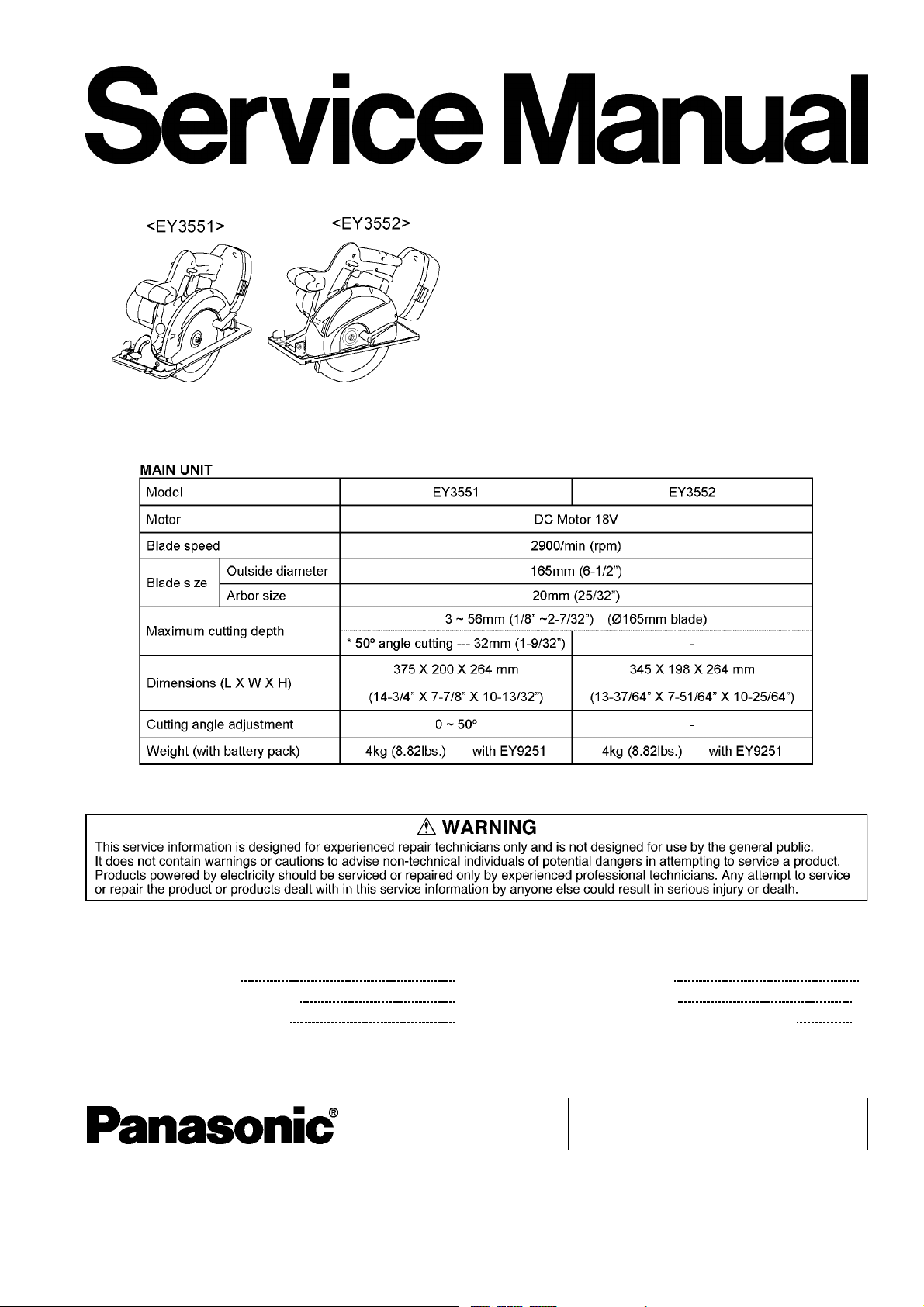
SPECIFICATIONS
ORDER NO.P T D0501U30C1
F16
Cordless Wood Saw / Cordless Metal Cutter
EY3551-U1
EY3552-U1
CONTENTS
Page Page
1 SCHEMATIC DIAGRAM 2
2 WIRING CONNECTION DIAGRAM
3 DISASSEMBLY INSTRUCTIONS
4 ASSEMBLY INSTRUCTIONS 7
2
5 TROUBLESHOOTING GUIDE
3
6 EXPLODED VIEW & REPLACEMENT PARTS LIST
© 2005 Matsushita Electric Works Ltd. All rights
reserved. Unauthorized copying and distribution is a
violation of law.
12
14
EY3551-U1 / EY3552-U1
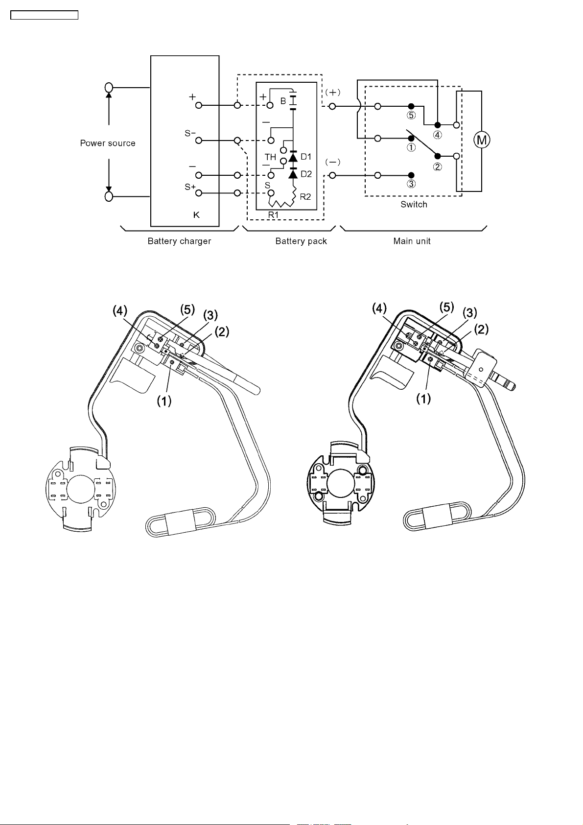
1 SCHEMATIC DIAGRAM
2 WIRING CONNECTION DIAGRAM
<EY3551> <EY3552>
2
3 DISASSEMBLY INSTRUCTIONS
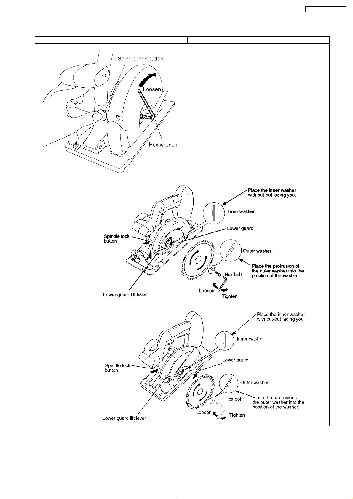
■BLADE REMOVAL.
Ref. No. 1A Procedure 1A Blade removal.
NOTE :
Make sure that the battery pack is removed from the saw prior
to servicing.
The blade will be hot right after cutting. Be sure to let the blade
cool down before removing it.
1. Hold the spindle lock button down. This prevents the blade from
rotating.
2. Use the provided hex wrench to loosen the hex bolt.
NOTE :
Keep the hex wrench in the storage slot on the body when not
using it.
3. Remove the hex bolt and outer washer.
4. Use the lower guard lift lever to open the lower guard.
5. Carefully remove the blade.
CAUTION:
Be careful to avoid cutting your hands on the blade.
EY3551-U1 / EY3552-U1
<EY3551>
<EY3552>
3
EY3551-U1 / EY3552-U1
■MAIN UNIT DISASSEMBLY. (The main unit can be opened without removing the shoe.)
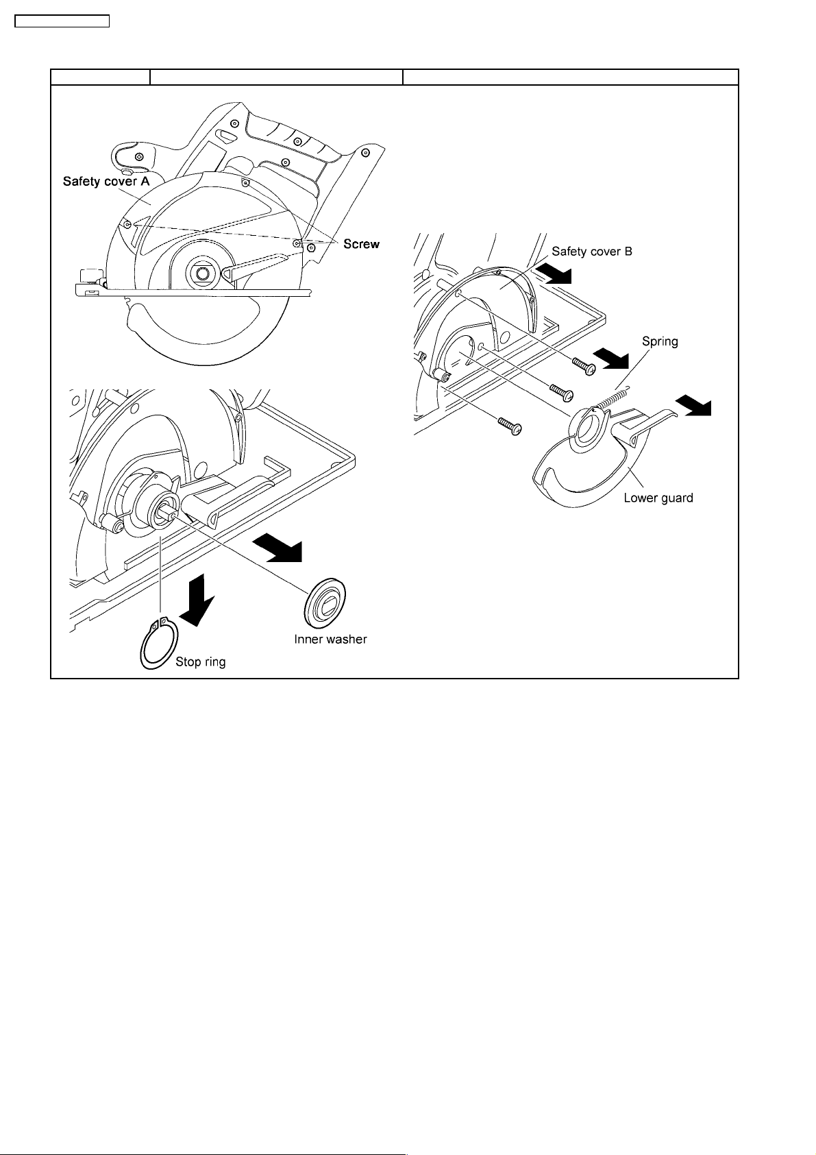
Ref. No. 2A Procedure 2A Removal of the safety cover and lower guard.
1. Loosen the base depth adjustment lever where located under the
grip of main unit and push the shoe down.
2. Remove the 3 screws securing the safety cover A. Take out the
safety cover A.
3. Remove the inner washer and the stop ring.
4. Remove the lower guard with connecting the spring.
5. Loosen the 3 screws and take out the safety cover B.
NOTE :
When removing the lower guard from the main unit, do not
stretch the spring.
4
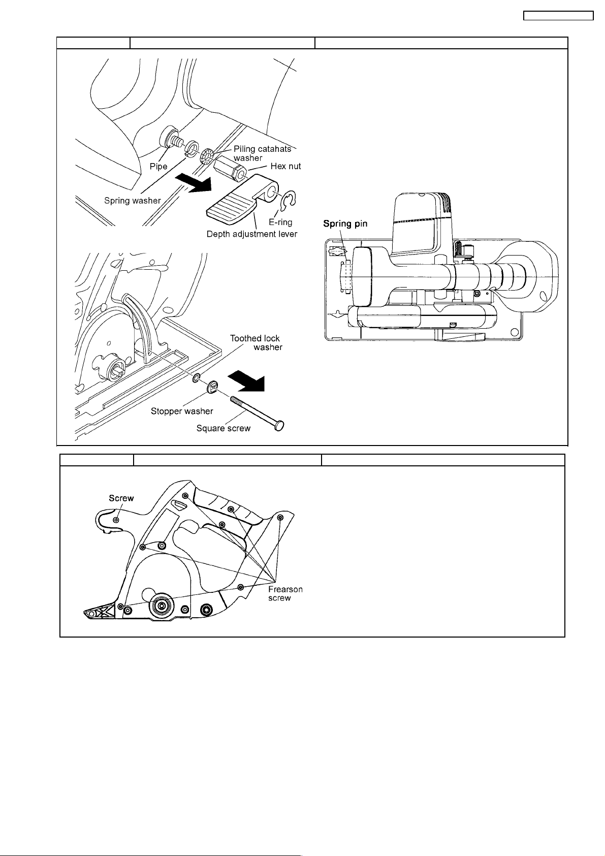
Ref. No. 2B Procedure 2A →→→→ 2B Removal of the shoe.
NOTE:
It is possible to disassemble the main unit without removing the
shoe.
1. Take out the E-ring and the depth adjustment lever.
2. Unscrew the hex nut.
3. Take out the spring washer and piling catahats washer.
4. Pull out the square screw and pipe.
5. Take out the stopper washer and toothed lock washer.
6. Push out the spring pin with a rod having a diameter of 5mm.
NOTE:
Do not tap the spring pin strongly. If to do so, the supporting
metal plates on both side of housing may cause the deformation.
EY3551-U1 / EY3552-U1
Ref. No. 2C Procedure 2A →→→→ 2C Removal of the Housing.
1. Loosen 7 housing screws (frearson type) and 1 (+) head screw.
It is then possible to disassembly the main unit or to check the
switch block and motor.
5
EY3551-U1 / EY3552-U1
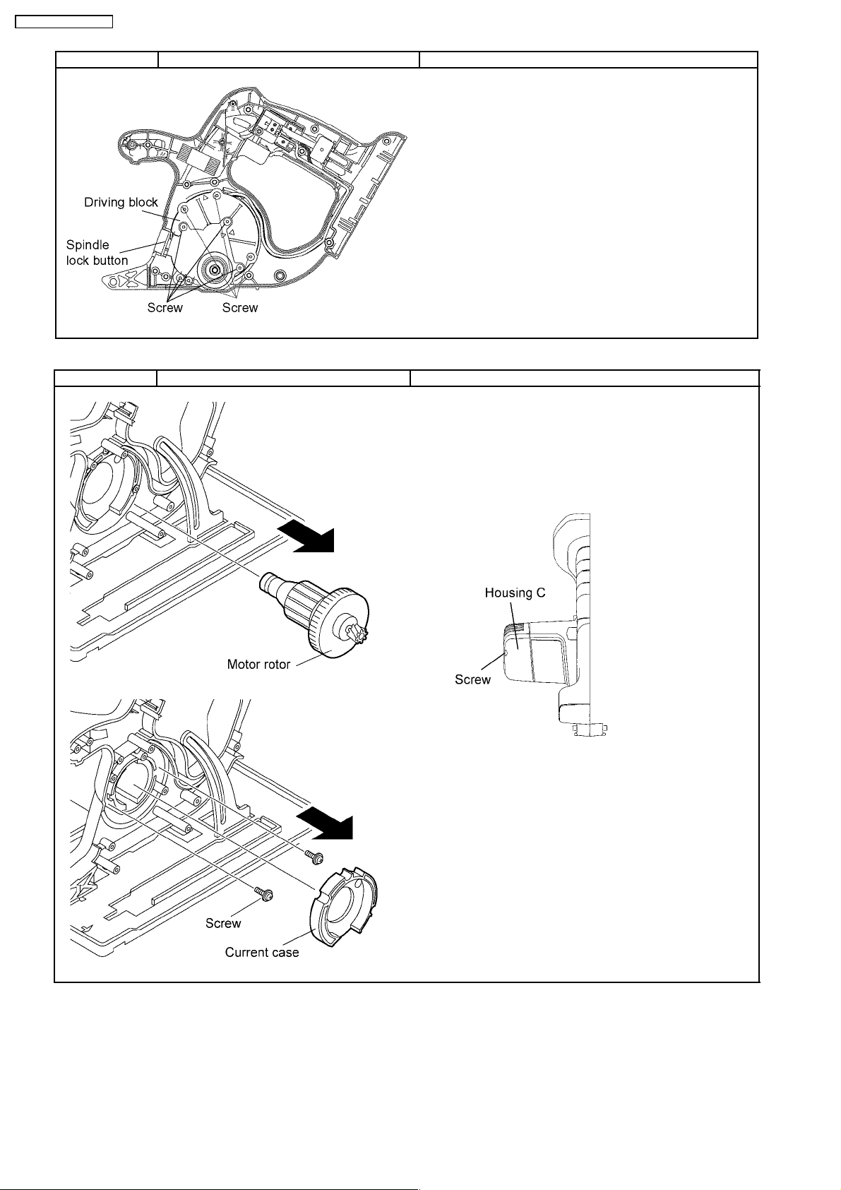
Ref. No. 2D Procedure 2A →→→→ 2C →→→→ 2D Removal of the gear box block.
1. Loosen the 4 screws where securing the driving block with the
housing in order to take out the gear box block from the main unit.
2. Remove the 4 screws and carefully open the gear box housing.
NOTE:
The internal parts of gear box block can be removed one after
another.
NOTE:
The spring of spindle lock button may pop out.
Ref. No. 2E Procedure 2A →→→→ 2C →→→→ 2D →→→→ 2E Assembly of the motor assembly.
1. Take out the motor rotor assembly from the motor stator.
2. Take out the current case.
3. Remove the 2 screws fastening the motor stator.
4. Take out the stator.
5. Take out the motor brush and switch assembly connected with
lead wires.
NOTE:
Loosen the 2 housing screws and take the housing C out for reassembling purpose.
6
 Loading...