

Page 1
SPECIFICATIONS
ORDER NO.PTD0310U42C1
F16
Reciprocating Saw
EY3544-U1
CONTENTS
Page Page
1 SCHEMATIC DIAGRAM 2
2 DISASSEMBLY INSTRUCTIONS
3 ASSEMBLY INSTRUCTIONS
4 TROUBLESHOOTING GUIDE 7
3
5 EXPLODED VIEW
6
6 REPLACEMENT PARTS LIST
© 2003 Matsushita Electric Works Ltd. All rights
reserved. Unauthorized copying and distribution is a
violation of law.
8
9
Page 2
EY3544-U1
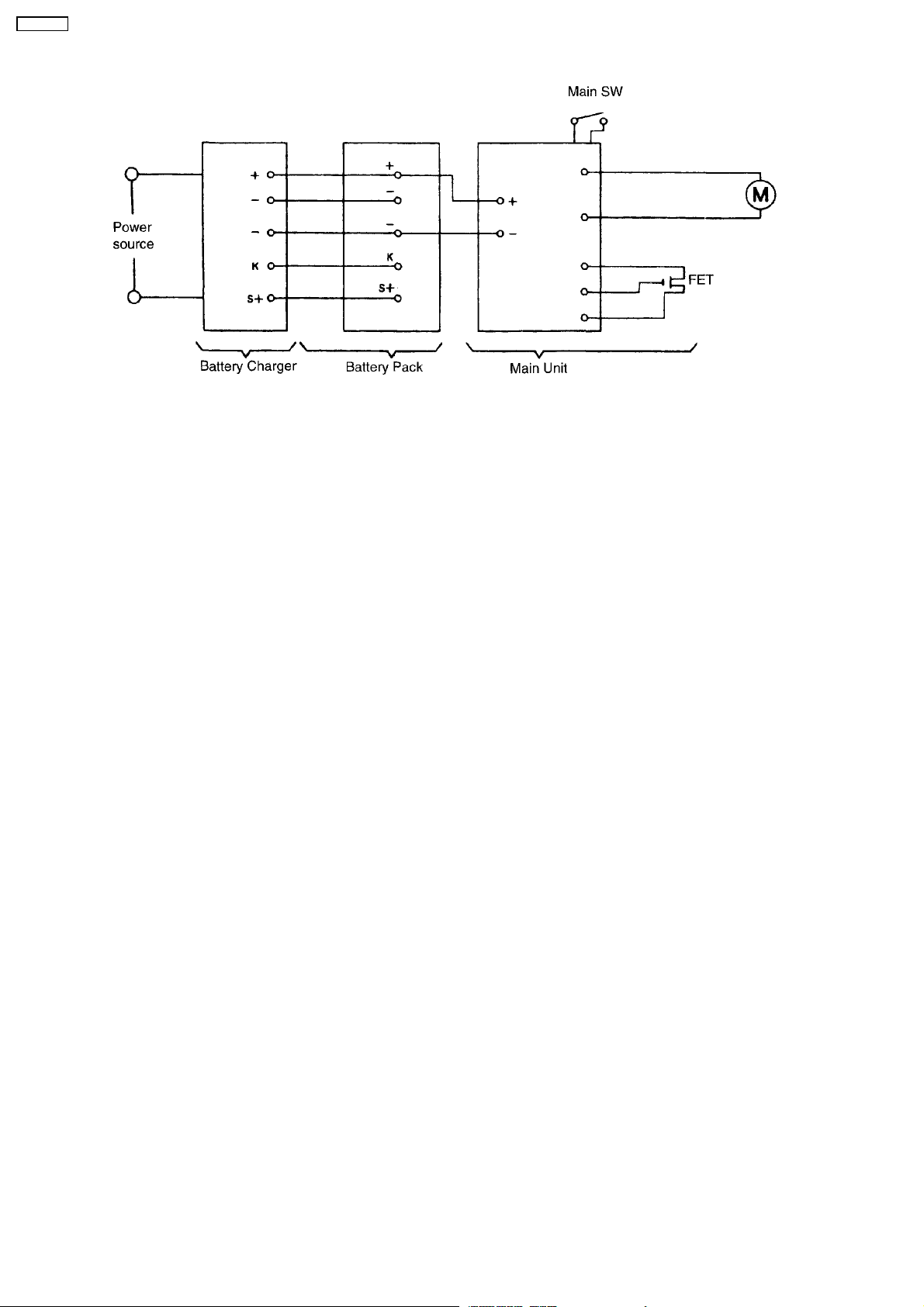
1 SCHEMATIC DIAGRAM
2
Page 3
2 DISASSEMBLY INSTRUCTIONS
■HOW TO DISASSEMBLE BLADE CLAMP ASSEMBLY.
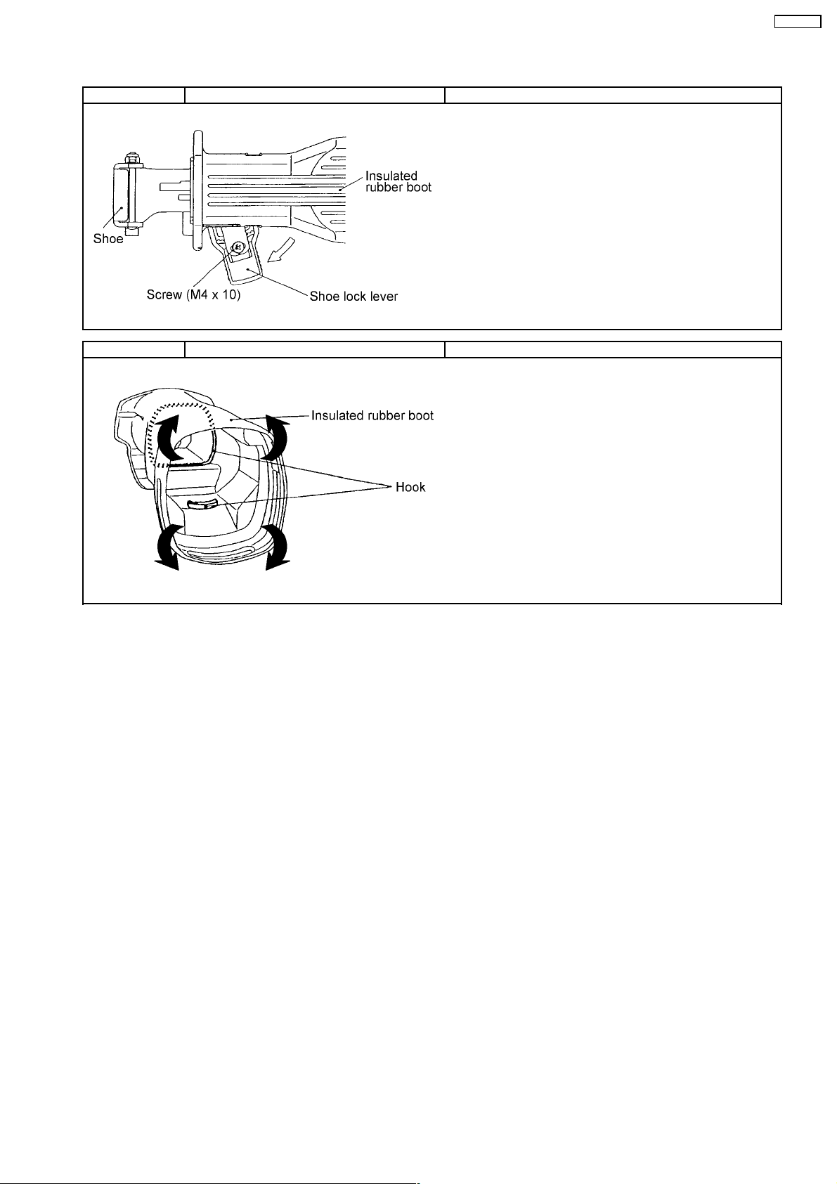
Ref. No. 1A Procedure 1A Removal of the shoe.
1. Loosen a screw (M4X10) with washer tightened on the rear side
of shoe lock lever.
2. Remove the shoe lock lever and loosen the hexagonal head bolt.
NOTE :
Make sure not to lose a hexagonal nut (M4) where located
inside of the shoe lock lever.
Ref. No. 1B Procedure 1A →→→→ 1B Removal of the insulated rubber boot.
1. Wind the insulated rubber boot down started from the motor
side.
NOTE :
The insulated rubber boot may not pull off due to scratched
badly inside of the hook.
EY3544-U1
3
Page 4

EY3544-U1
Ref. No. 1C Procedure 1A →→→→ 1B →→→→ 1C Removal of the blade clamp block.
1. Loosen four screws (M5X18) where tightening on the gear
housing.
■HOW TO DISASSEMBLE GEAR CASE or MOTOR ASSEMBLY.
Ref. No. 1D Procedure 1A →→→→ 1B →→→→ 1D Removal of the housing.
1. Loose seven housing screws (4X18).
2. Open the housing B.
3. Take out the motor with gear case assembly from the housing A.
4
Page 5

Ref. No. 1E Procedure 1A →→→→ 1B →→→→ 1D →→→→ 1E Removal of the motor housing.
1. Remove the holder cap and take out the carbon brush on right and
left side.
2. Loosen four tapping screws (5X35) tighten the gear case.
3. Pull out the gear case assembly from the motor housing.
EY3544-U1
Ref. No. 1F Procedure 1A →→→→ 1B →→→→ 1D →→→→ 1E →→→→ 1F →→→→1CRemoval of the gear case block.
1. Loosen two screws (M4X12) and pull out the rotor assembly.
2. Follow the procedure 1C.
NOTE:
Greasing No. 1 grease about 10g into the gear for reassembly.
5
Page 6

EY3544-U1
3 ASSEMBLY INSTRUCTIONS
■ HOW TO ASSEMBLE SWITCH.
Ref. No. 1A Procedure 1A Attachment of the brush holder.
1. Insert the brush holders on both right and left side.
2. Press fit the lead wires into the lead guide A.
3. Press fit the lead wires into the lead guide B.
4. Insert the carbon brushes.
5. Tighten the holder caps.
Ref. No. 1B Procedure 1A →→→→ 1B Attachment of the switch.
1. Check the lead wires whether they are mounted in the proper
position.
NOTE:
Make sure they are not set on the screw bosses or over the
housing ribs.
6
Page 7

4 TROUBLESHOOTING GUIDE
< TROUBLE > < CHECK > < REMEDY >
Does not operate. <CHECK BATTERY PACK.> NO Replace battery pack.
→
If no less than 18V DC is available across the (+) and (-) terminals
after charging for the rated charging time
(approx. 65 minutes for EY9250), the battery pack is OK.
NOTE:
<CHECK TERMINAL CONNECTIONS BETWEEN MAIN UNIT NO Repair contacts.
Check for proper terminal contacts.
Check continuity between following terminals. Replace switch &
1) Inspection of the switch operated contact. FET block.
2) Inspection of the brake.
The battery pack is sold separately as an optional accessory.
See the nearest sales dealer for details. Th e battery pack has a
limited life.
The pack should be replaced if;
- after being charged for the rated charging time the battery
voltage is less than 18V DC or the usable time is extremely short.
- the battery leaks. Check battery for leaks and terminals for
corrosion
↓OK
AND BATTERY PACK.>
↓OK
<CHECK SWITCH BLOCK.> NO Contacts in switch block
(See WIRING CONNECTION DIAGRAM.)
When switch handle is depressed all the way:
- There should be 0Ω between (A) - (D) , and between (B) - (C) ;
when switch lever is set to forward side.
When switch handle is not depressed:
- There should be 0Ω between (A) - (B)
→
→
→
are defective.
EY3544-U1
↓OK
<CHECK CARBON BRUSH.> NO Replace carbon
1) The condition of carbon brush.
- There should be more than 1mm from the line of the carbon brush.
2) The continuity of carbon brush.
- There should be 0Ωbetween the motor lead wire and the
metal fitting of carbon brush.
↓OK
<CHECK MOTOR ROTOR.> NO Replace motor
Check the condition of rotor if there is any wear, crack and deformation.
↓OK
<CHECK MOTOR STATOR.> NO Replace motor
Check the condition of motor case if there is any crack and deformation.
Does not speed- <CHECK SWITCH.> NO Repair the contact
control.
→
Follow the procedure above “CHECK SWITCH”.
Attach the battery pack and confirm the switch operation & FET block.
when depressing the switch handle little by little.
→
brushes.
→
rotor assembly.
→
stator.
→
or replace switch
7
Page 8

EY3544-U1
5 EXPLODED VIEW
8
Page 9

6 REPLACEMENT PARTS LIST
NOTE:
*B=only available as set
*C=available individually
Ref.No. Part No. Part Name & Description Remarks Per Unit
1 WEY3544K6708 SCREW *C M5*18 4
2 WEY3544S1168 BLADE CLAMP BLOCK 1
3 WEY3544K0228 SHOE 1
4 WEY3544H3648 INSULATED RUBBER BOOT 1
5 WEY3544K6278 SCREW M4*10 1
6 WEY3544K0478 SLEEVE 1
7 WEY3544K1168 INNER PLATE 1
8 WEY3544K1178 LOCK PLATE 1
9 WEY3544K1558 SHOE LOCK LEVER 1
10 WEY3544K6398 HEXAGONAL HEAD BOLT M8*25 1
11 WEY3544K6428 HEXAGONAL NUT M4 1
12 WEY3544S1768 GEAR CASE BLOCK 1
13 WEY3544L9388 TAPPING SCREW *C 5*35 4
14 WEY3544L4628 MOTOR ROTOR ASSEMBLY 1
15 WEY3544L6218 SCREW *C M4*12 2
16 WEY3544L0478 BAFFLE PLATE 1
17 WEY3544L9668 TAPPING SCREW *C 4*60 2
18 WEY3544L1188 STATOR 1
19 WEY3544K0538 MOTOR HOUSING 1
20 WEY3544K0558 HOLDER CAP *B (2PCS/PK) 2
21 WEY3544L4638 CARBON BRUSH *B (2PCS/PK) 2
22 WEY3544L4368 BRUSH HOLDER 1ST
23 WEY3544K3078 HOUSING AB SET 1
24 WEY3544L0178 SPRING 1
25 WEY3544Y3568 RELEASE LEVER 1
26 WEY3544L6208 SCREW M3*8 1
27 WEY3544L0088 SWITCH FRAME 1
28 WEY3544K9218 TAPPING SCREW *C 4*18 7
29 WEY3544L2568 HEAT SINK 1
30 WEY3544L0208 HOLDER PLATE 1
31 WEY3544Y2008 SWITCH 1
- WEY3544K8108 OPERATING INSTRUCTIONS 1
EY3544-U1
**Battery Pack, and Tool Case are available as an optional accessory.
See the nearest sales dealer for details.
***For replacement parts of charger, see the charger service manual.
Charger complete set is available as an optional accessory. See the nearest sales dealer for details.
9
 Loading...