

Page 1
Detection
liquid leakage
!
Detection
liquid leakage
!
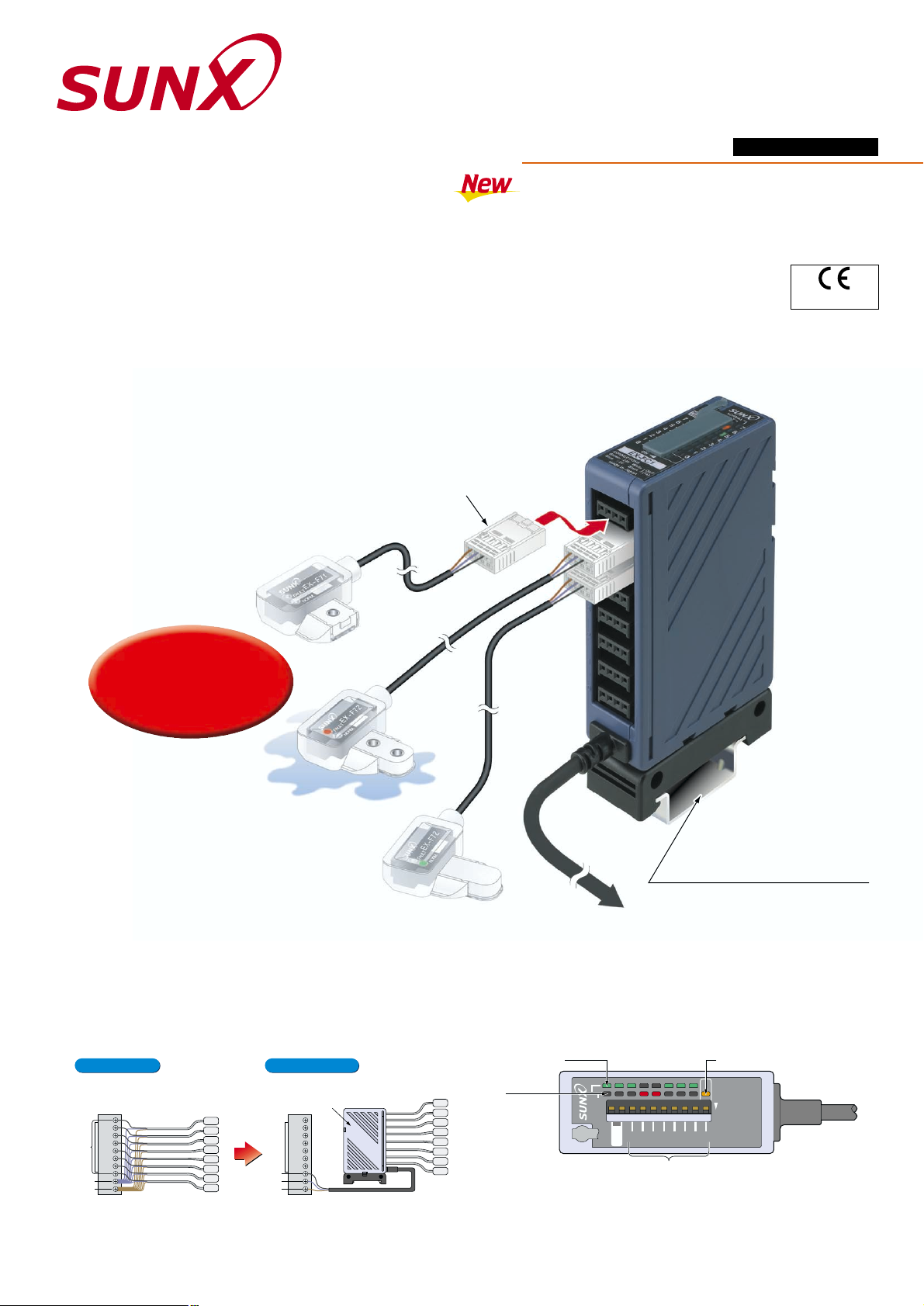
Simple Wire-saving Unit
for Leak Detection Sensor
EX-FC1
Unit mounting bracket
MS-DIN-3 (Optional)
(Compatible with 35 mm 1.378 in wide DIN rail)
Male snap connector
SL-CP1 (Accessory)
Amplifier built-in leak detection sensor
(PVC mounting bracket type)
EX-F72
Amplifier built-in leak detection sensor
(SUS mounting bracket type)
EX-F71
Two-point-fixing
Adhesive fixing
To PLC
NORMAL
FAULT
ON
NOT
USED
7654321
0
7654321
0
Space savings are significant, as the ultra-thin & compact EX-FC1
has main unit body dimensions of only W20 0.787H80
3.15D52 mm 2.047 in
Slim & compact
Connections are made by simply inserting the leak detection sensor
cable leads into the male snap connector SL-CP1, then pressing down
until the connector snap-locks!
This saves the user the time and the trouble of stripping the insulation
from each lead before attaching the leads to terminals.
SIMPLE WIRE-SAVING UNIT
EX-FC1
Normal indicators
(Green)
Output indicator (Orange)
Error
indicators
(Red)
Connection setting switch
EX-FC1 is a simple wire-saving unit for exclusive use with EX-F71/72 leak
detection sensors.
The EX-FC1 integrates the outputs from up to 8 leak detection sensors
into a single OR output, allowing for significant wiring space savings.
* Even with only one leak detection sensor connected, an OFF signal is output
if the sensor detects liquid leakage, or if the unit has been installed incorrectly.
In addition to an output indicator which allows users to verify output
status, there are 2 built-in operation indicator lights (normal
operation / malfunctioning) for each channel.
The indicator lights (normal operation / malfunctioning) enable verification
of leakage detection status and correct installation of leak detection
sensors, all at a glance.
Conventional Using EX-FC1
EX-FC1
mPlease arrange the leak detection sensor separately.
0 V
Output
V
0 V
Output
V
Conforming to
EMC Directive
Newly Released Wire-saving Unit Made Especially for Connecting
Leak Detection Sensors!
Saves wiring! Now connects up to
8 leak detection sensors 3 indicators provide operational confirmation
Connects easily with one-touch connector
Takes up 8 input terminals, one for each of
the 8 leak detection sensors connected.
Only 1 input terminal is needed to handle
connection to 8 leak detection sensors!
For leak detection sensor
Page 2
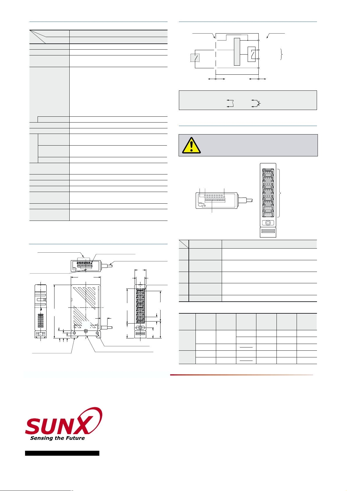
SPECIFICATIONS I/O CIRCUIT DIAGRAM (For one channel)
PRECAUTIONS FOR PROPER USE
Operation matrix for each indicator
FUNCTIONAL DESCRIPTION
Designation
Simple wire-saving unit for leak detection sensor
EX-FC1
Model No.
Indicators
DIMENSIONS (Unit : mm in)
Item
Never use this product in a device for personnel
protection.
2-"4.5 0.177 mounting holes
11.5
(
0.453
)
52 2.047
9
0.354
13
0.512
93
3.661
4
0.157
Unit mounting
base (
MS-SL-2
)
Applicable to 35 mm 1.378 in DIN rail
25.5
1.004
29.5
1.161
Connected
Unconnected
Unconnected
Connected
ON
Not leaked
Lights up
Lights off
Lights up
Lights off
Lights off
Lights up
Lights off
Lights up
Lights up
Lights off
Lights up
Lights off
Lights up
Lights off
Lights off
Leaked
Not leaked
OFF
ON
OFF
18.3 0.728
14.6
0.575
20
0.787
7.5 0.295
52.5
2.067
60.5
2.382
Normal indicators (Green),
Error indicators (Red)
Connection setting switch
Output indicator (Orange)
7
6
5
4
3
2
1
0
"3.7 0.146 cable 2 m 6.562 ft long
8-connectors
Main circuit
Internal circuit
Terminal No. Wire color
(Brown) 12 to 24 V DC10 %12 to 24 V DC10 %
(White) OUT
(Black) OUT
(Blue) 0 V
Sensor side
Non-voltage contact or NPN open-collector transistor (Amplifier built-in leak detection sensor)
IN
0 V
Not
connected
1
3
2
4
Users’ circuit
m1
m1
Relay contact
(1a contact)
or
123
4
5
7
6
5
4
3
2
1
0
1
2
3
Output indicator
(Orange LED)
Light up when the sensor is connected to each
channel and the connection setting switch is set to ON
Light up when a leak is detected by a sensor connected
to each channel or a sensor is mounted improperly
Lights up when the output relay is ON (normal)
4
5
Connector
Connect the leak detection sensors
Description Function
Operation
Normal
Error
Connection
state of the leak
detection sensor
State of
connection
setting switch
Leak
detected
condition
Normal
indicator
(Green)
Error
indicator
(Red)
Output
indicator
(Orange)
Normal indicators
(Green LED
8)
Error indicators
(Red LED
8)
Set the switch to ON when the leak detection sensor is connected,
set to OFF when the leak detection sensor is not connected
Connection
setting switches
40
1.575
()
(
)
No. LCE-EXFC1-5 May, 2002
2431-1 Ushiyama-cho, Kasugai-shi, Aichi,
486-0901, Japan
Phone: +81-(0)568-33-7211
FAX: +81-(0)568-33-2631
SUNX Limited
Phone: +81-(0)568-33-7861
FAX: +81-(0)568-33-8591
Overseas Sales Dept.
Printed on 100% recycled paper PRINTED IN JAPAN
http://www.sunx.co.jp/
All information is subject to change without prior notice.
Note 1:
The protective caps (SC-PK) used to protect the connectors, are available for sale
separately.
Output
SL-CP1
12 to 24 V DC
10 % Ripple P-P 10 % or less
50 mA or less (for the unit itself),
135 mA or less (including the sensor input current when all outputs of sensors are ON)
The output relay is ON when the input signal from the sensor is ON
5 ms or less (excluding the response time of the sensor)
8 Nos.
35 to 85 % RH, Storage: 35 to 85 % RH
Enclosure: ABS, Terminal part: POM
0.2 mm
2
4-core cabtyre cable, 2 m 6.562 ft long
85 g 2.998 oz approx.
Output operation
Response time
Input No.
Normal
Error
Output
Ambient temperature
Ambient humidity
Material
Cable
Cable extension
Weight
Accessories
Applicable connector
Supply voltage
Current consumption
Relay contact 1a
• Switching capacity: Less than 50 V 0.3 A AC (resistive load)
However, if CE conformity is not required,
this can be used with 125 V 0.3 A AC.
30 V 1 A DC (resistive load)
• Min. applied load: 10 mV 10!A DC
•
Electrical lifetime: 100,000 times or more
(rated load, switching frequency 20 times / min.)
•
Mechanical lifetime: 50 million times or more
(switching frequency 80 times / min.)
Green LED8
Light up when the sensor is connected to each channel
and the connection setting switch is set to ON
Red LED8
Light up when a leak is detected by a sensor connected
to each channel or a sensor is mounted improperly
Orange LED [Lights up when the output relay is ON (normal)]
SL-CP1 (Male snap connector): 8 Nos.
MS-SL-2 (Unit mounting base): 1 No.
Extension up to total less than 10 m 32.808 ft is
possible, with 0.3 mm
2
, or more, cable.
10 to 60 C 14 to 140 F (No dew condensation or icing allowed),
Storage: 20 to 70 C 4 to 158 F
 Loading...