

Page 1
2 mode Noise Filters
28
Typ e:
EXC24CB/CP
EXC24CN
2 mode Noise Filters
■ Features
● Burst/radiation noise fi ltering for audio circuits
● The optimally magnetic-coupled ferrite beads allow for
the fi ltering of both common and normal mode noises
● The strong multi-layer structure provides high resistance
to refl ow soldering heat and a high mounting reliability
● Magnetic shield type
● High Impedance : 220 to 1 kΩ(EXC24CB type)
● Low Resistance Value : 0.4 Ω max. (EXC24CP type)
● High Impedance : 600 Ω,
Low Resistance Value : 0.9 Ω max. (EXC24CN type)
● RoHS compliant
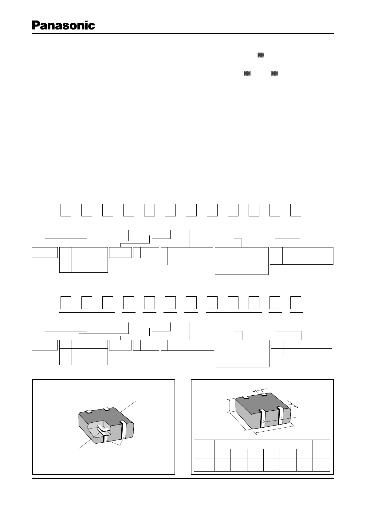
■ Explanation of Part Numbers
EXC24CB/CP Type
●
Noise Filter
1
&
Code
2
2
9
Product Code Type
Dimensions(mm)
1.25 L 1.00 L 0.50
(L) L (W) L (H)
3
$
4 Terminals
4
Size Nominal Impedance Form Suffix
5
Number of
Terminals
Coupled
C
type
6
$
High Impedance Type
B
Low DCR Type
P
■ Recommended Applications
● Receiver lines, speaker lines, microphone lines and
headset of mobile phones.
● Audio signal lines of Portable audio equipment, PCs,
PDAs.
7
#
Characteristics
8
9
The first two digits are
significant figure of
impedance value, and the
third one denotes the
number of zeros following
10
11 12
6
Code
U
Packing
Embossed Carrier Taping
EXC24CN Type
●
Noise Filter
1
&
Code
2
2
9
Product Code Type
Dimensions(mm)
1.25 L 1.00 L 0.50
(L) L (W) L (H)
3
$
4 Terminals
4
Size Nominal Impedance Form Suffix
5
Number of
Terminals
Coupled
C
type
6
$
High Impedance Type
N
and Low DCR Type
7
/
Characteristics
8
9
The first two digits are
significant figure of
impedance value, and the
third one denotes the
number of zeros following
10
11 12
9
Code
X
■ Construction ■ Dimensions in mm (not to scale)
F
Ferrite
C
A
B
Dimensions (mm)
Inner Conductor
Electrode
Typ e
(inch size)
EXC24C
(0504)
ABCDEF
1.00±0.15 1.25±0.15 0.50±0.10 0.20±0.15 0.65±0.10 0.35±0.10
Packing
Pressed Carrier Taping
D
E
Mass
(Weight)
[mg/pc.]
3
Design and specifi cations are each subject to change without notice. Ask factory for the cu rrent technical specifi cations before purchase and/or use.
Should a safety c oncern ar ise regarding th is product , please be sure to contact us immediately.
Nov. 2011202
Page 2
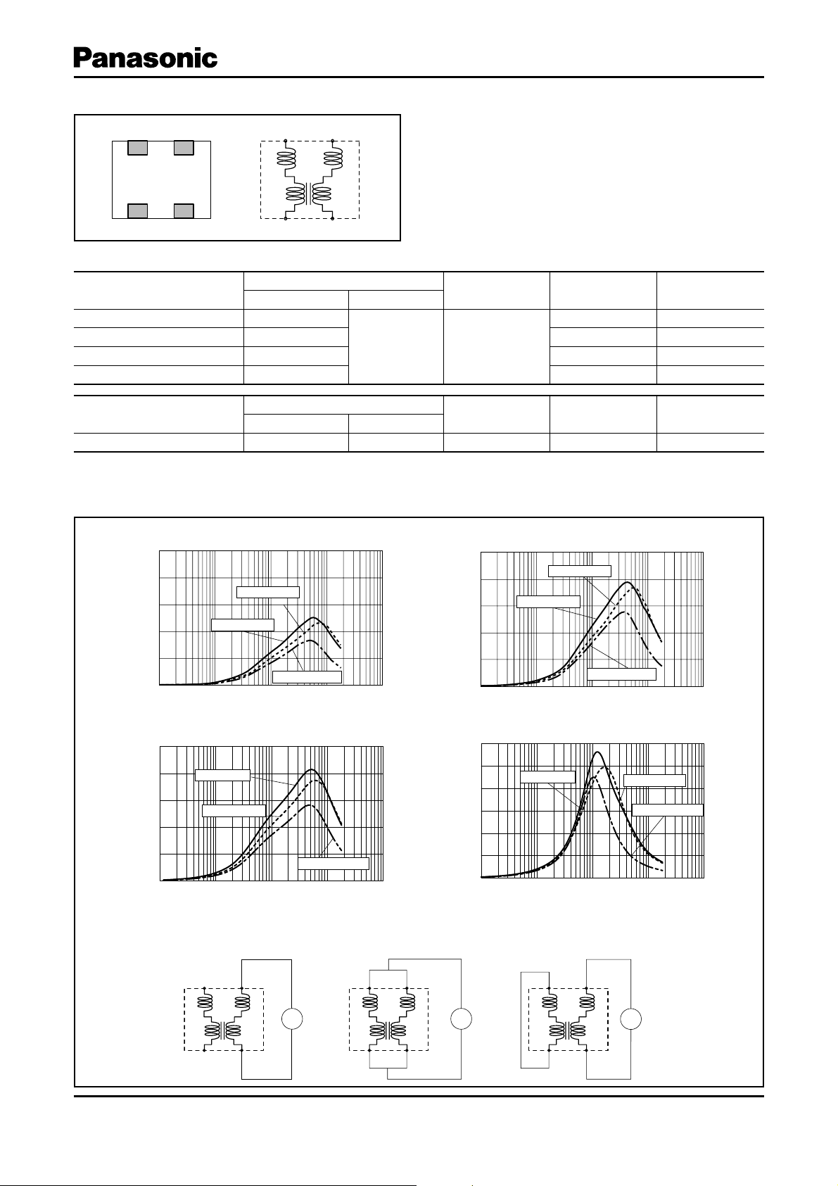
■ Circuit Con guration (No Polarity)
29
2 mode Noise Filters
43
12
43
12
■ Ratings
Part Number
Impedance (Open mode)
(Ω) at 100 MHz Tolerance(%)
EXC24CP121U 12 0
EXC24CP221U 220 350 0.4
EXC24CB221U 220 100 0.7
±25 5
EXC24CB102U 1000 50 1.5
Part Number
EXC24CN601X 600
Category Temperature Range –40 °C to +85 °C
●
Impedance (Common mode)
(Ω) at 100 MHz Tolerance(%)
±25 5 200 0.9
Rated Voltage
(V DC)
Rated Voltage
(V DC)
Rated Current
(mA DC)
500 0.3
Rated Current
(mA DC)
■ Impedance Characteristics (Typical)
EXC24CP121U
●
500
400
300
200
Impedance(?)
100
0
1 10 100 1000 10000
EXC24CB221U
●
500
400
300
200
Impedance(?)
100
0
1 10 100 1000 10000
Normal mode
Open mode
Common mode
Frequency(MHz)
Open mode
Normal mode
Common mode
Frequency(MHz)
EXC24CP221U
●
500
400
300
200
Impedance(?)
100
0
1 10 100 1000 10000
EXC24CB102U
●
1200
1000
800
600
400
Impedance(?)
200
0
1 10 100 1000 10000
Normal mode
Open mode
Common mode
Frequency(MHz)
Open mode
Frequency(MHz)
DC Re sis tance
(Ω) max.
DC Re sis tance
(Ω) max.
Normal mode
Common mode
Measurement Circuit
●
(A)Open Mode (B)Common Mode (C)Normal Mode
;
Design and specifi cations are each subject to change without notice. Ask factory for the cu rrent technical specifi cations before purchase and/or use.
Should a safety c oncern ar ise regarding th is product , please be sure to contact us immediately.
;
;
Nov. 2011202
Page 3

■ Impedance Characteristics (Typical)
30
2 mode Noise Filters
EXC24CN601X
●
1600
1400
1200
1000
800
600
Impedance(?)
400
200
–
1 10 100 1000 10000
Differential mode
Open mode
Common mode
Frequency(MHz)
Measurement Circuit
●
(A)Open Mode
(C)Differential Mode
(B)Common Mode
;
;
;
■ Packaging Methods (Taping)
● Standard Quantity
Part Number Kind of Taping Pitch (P1)Quantity
EXC24CP□□□U
EXC24CB□□□U
EXC24CN□□□X Pressed Carrier Taping 2 mm 10000 pcs./reel
Embossed Carrier Taping
●
t1
Sprocket hole Compartment
t2
Chip component
Embossed Carrier Taping 4 mm 5000 pcs./reel
Pressed Carrier Taping
●
fD0
A
B
P1 P2 P0
FE
W
Tape running direction
Sprocket hole
B
A
t2
Chip component
P0 P2
P1
Tape running direction
Compartment
fD0
E
F
W
Taping Reel
●
T
fC
fD
E
fA
fB
W
Embossed Carrier Dimensions (mm)
Part Number
EXC24CP□□□U
EXC24CB□□□U
ABWFEP
1
1.20±0.15 1.45±0.15 8.0±0.2 3.5±0.1 1.75±0.10 4.0±0.1 2.0±0.1 4.0±0.1 1.5±0.1 0.25±0.05 0.90±0.15
P
2
P
0
D
0
t
0
1
Pressed Carrier Dimensions (mm)
Part Number
EXC24CN□□□X
ABWFEP
1
1.14±0.10 1.38±0.15 8.0±0.2 3.5±0.1 1.75±0.10 2.0±0.1 2.0±0.1 4.0±0.1 1.5±0.1 0.68±0.10
P
2
P
0
D
0
0
Standard Reel Dimensions (mm)
Part Number
A
0
B
0
C
0
DE W T
0
EXC24C□□□□ 180.0±3.0 60.0±1.0 13.0±0.5 21.0±0.8 2.0±0.5 9.0±0.3 11.4±1.5
Design and specifi cations are each subject to change without notice. Ask factory for the cu rrent technical specifi cations before purchase and/or use.
Should a safety c oncern ar ise regarding th is product , please be sure to contact us immediately.
t
2
t
2
Nov. 2011202
Page 4

■ Recommended Land Pattern Design
31
B
EF E
A
DCD
■ Recommended Soldering Conditions
Recommendations and precautions are described below.
Recommended soldering conditions for refl ow
●
· Refl ow soldering shall be performed a maximum of
two times.
· Please contact us for additional information when
used in conditions other than those specifi ed.
· Please measure the temperature of the terminals
and study every kind of solder and printed circuit
board for solderability be fore ac tu al use.
Peak
2 mode Noise Filters
Dimension (mm)
A 1.50 to 1.90
B1.10
C0.50
D 0.50 to 0.70
E0.40
F0.30
For soldering (Example : Sn-37Pb)
Temperature Time
Preheating 140 °C to 160 °C 60 s to 120 s
Main heating Above 200 °C 30 s to 40 s
Peak 235 ± 10 °C max. 10 s
Preheating
For lead-free soldering (Example : Sn/3Ag/0.5Cu)
Temperature Time
Temperature
Heating
Preheating 150 °C to 170 °C 60 s to 120 s
Main heating Above 230 °C 30 s to 40 s
Peak max. 260 °C max. 10 s
Time
Flow soldering
●
· We do not recommend fl ow soldering , because fl ow soldering may cause bridges between the electrodes.
<Repair with hand soldering>
Preheat with a blast of hot air or similar method. Use a soldering iron with a tip temperature of 350 °C or less. Solder
●
each electrode for 3 seconds or less.
Never touch this product with the tip of a soldering iron.
●
Safety Precautions
The following are precautions for individual products. Please also refer to the common precautions for Noise Suppression
Device shown on this catalog.
1. Use rosin-based fl ux or halogen-free fl ux.
2. For cleaning, use an alcohol-based cleaning agent. Before using any other type, consult with our sales person
in advance.
3. Do not apply shock to 2 mode Noise Filters (hereafter called the fi lters) or pinch them with a hard tool (e.g. pliers and tweezers). Otherwise, their bodies may be chipped, affecting their performance. Excessive me chanical
stress may damage the fi lters. Handle with care.
4. Store the fi lters in a lo ca tion with a temperature ranging from −5 °C to +40 °C and a relative humidity of 40 % to 60 %,
where there are no rapid changes in temperature or humidity.
5. Use the fi lters within half a year after the date of the outgoing inspection indicated on the packages.
Design and specifi cations are each subject to change without notice. Ask factory for the cu rrent technical specifi cations before purchase and/or use.
Should a safety c oncern ar ise regarding th is product , please be sure to contact us immediately.
Nov. 2011202
 Loading...