

Page 1
EX-10
2-color indicator
Red: Operation indicator
(
Green: Stability indicator
)
SENS.SENS.
EXEX
-17-17
SENS.SENS.
EXEX
-17-17
Operation mode switch
Operation indicator
(Orange)
Even for the thru-beam
type sensor, only three
wires have to be connected.
Conforming to EMC Directive
(Excluding EX-15/17)
UL Recognition
(Excluding 5 m cable length type)
08/2005
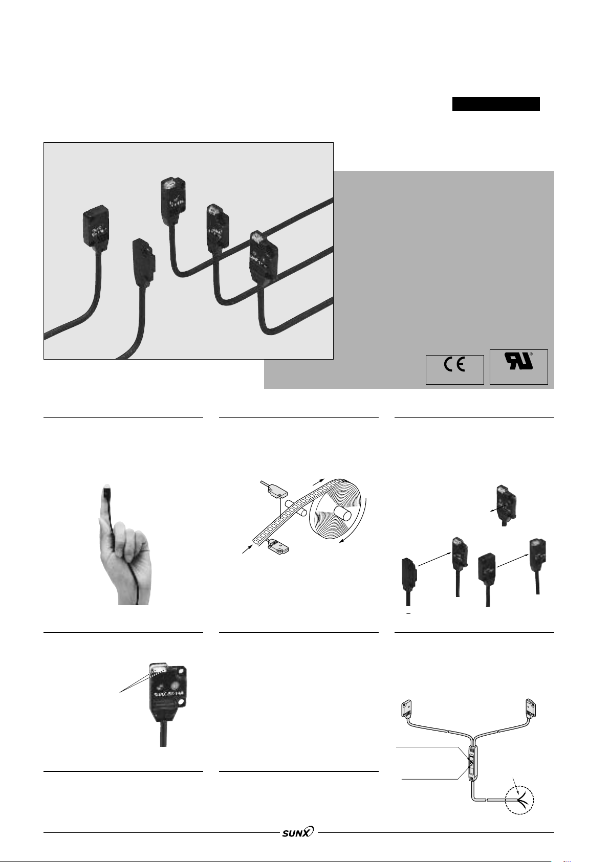
SERIES
Ultra-slim Photoelectric Sensor
Amplifier built-in
extraordinarily small
and slim size
Amplifier Built-in
Smallest body, just 3.5 mm 0.138 in thick
It can be mounted in a very small space
as its size is just W10
W0.394
beam, front sensing type).
H0.571 D0.138 in (thru-
H14.5D3.5 mm
High-speed response time: 0.5 ms
The sensor is suitable for detecting
small and high-speed traveling objects.
Bright 2-color indicator Waterproof
A convenient 2-color indicator has
been incorporated in the miniature
body.
The sensor can be hosed down
because of its IP67 construction and
the non-corrosive stainless steel
mounting bracket.
Note: However, take care that if it is exposed to
water splashes during operation, it may
detect a water drop itself.
Flexible mounting
The diffuse reflective type sensor is
front sensing and is so thin that it gives
an impression of being just pasted on
the mounting base. The thru-beam
type is available as front sensing type,
as well as, side sensing type, allowing
flexible mounting.
Diffuse reflective
• Front sensing type
Thru-beam
• Front sensing type • Side sensing type
Operation mode switch
Thru-beam type sensor incorporated
with an operation mode switch on the
bifurcation is also available. It helps
you to test the operability before startup.
Ten times durable
Flexible cable on EX-10-R is 10 times
as durable as conventional model. It is
most suitable for moving parts, such as
robot arm, etc.
226
Red beam makes beam alignment easy
The red LED beam projected from the
emitter helps you to align the sensor
heads.
Page 2
EX-10
EX-14
Transparent stick
IC
EX-15
EX-19
EX-14
Guide
EX-13E
EX-14
M3 screws
M3 screws
M3 screws
1 m
3.281 ft
The best distance is
approx. 10 mm 0.394 in
from the object.
08/2005
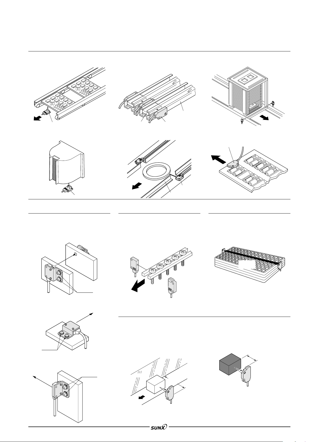
APPLICATIONS
Verifying position of PCBs Detecting ICs Detecting PCB rack
Detecting wafer cassette Detecting thin ring Checking for absence of capacitor
in tray
Mountable with M3 screws
Non-corrosive stainless steel type
mounting bracket is also available.
•
MS-EX10-1 [Cold rolled carbon steel (SPCC)]
and MS-EX10-11 [Stainless steel (SUS304)]
(mounting bracket for the front sensing type)
Minimum sensing object: "1 mm "0.039 in
EX-11, EX-11E, EX-15 and EX-15E
are incorporated with "1 mm "0.039 in
slit masks so that "1 mm "0.039 in, or
more, object can be detected. Hence,
they are suitable for precise positioning or
Long sensing range: 1 m 3.281 ft (EX-19)
A sensing range of 1 m 3.281 ft has
been realized with a slim size of just
3.5 mm 0.138 in. It can be used to
detect even wide IC trays.
small parts detection.
•
MS-EX10-2 [Cold rolled carbon steel (SPCC)]
and MS-EX10-12 [Stainless steel (SUS304)]
(mounting bracket for the side sensing type)
•
MS-EX10-3 [Cold rolled carbon steel (SPCC)]
and MS-EX10-13 [Stainless steel (SUS304)]
(L-shaped mounting bracket)
Background suppression (EX-14)
• Not affected by background
Even a specular background separated by 100 mm 3.937 in, or more,
is not detected.
However, the background should be
()
directly opposite.
Background
100 mm
3.937 in
• Black object reliably detected
It can reliably detect dark color objects since it is convergent reflective
type.
227
Page 3
EX-10
08/2005
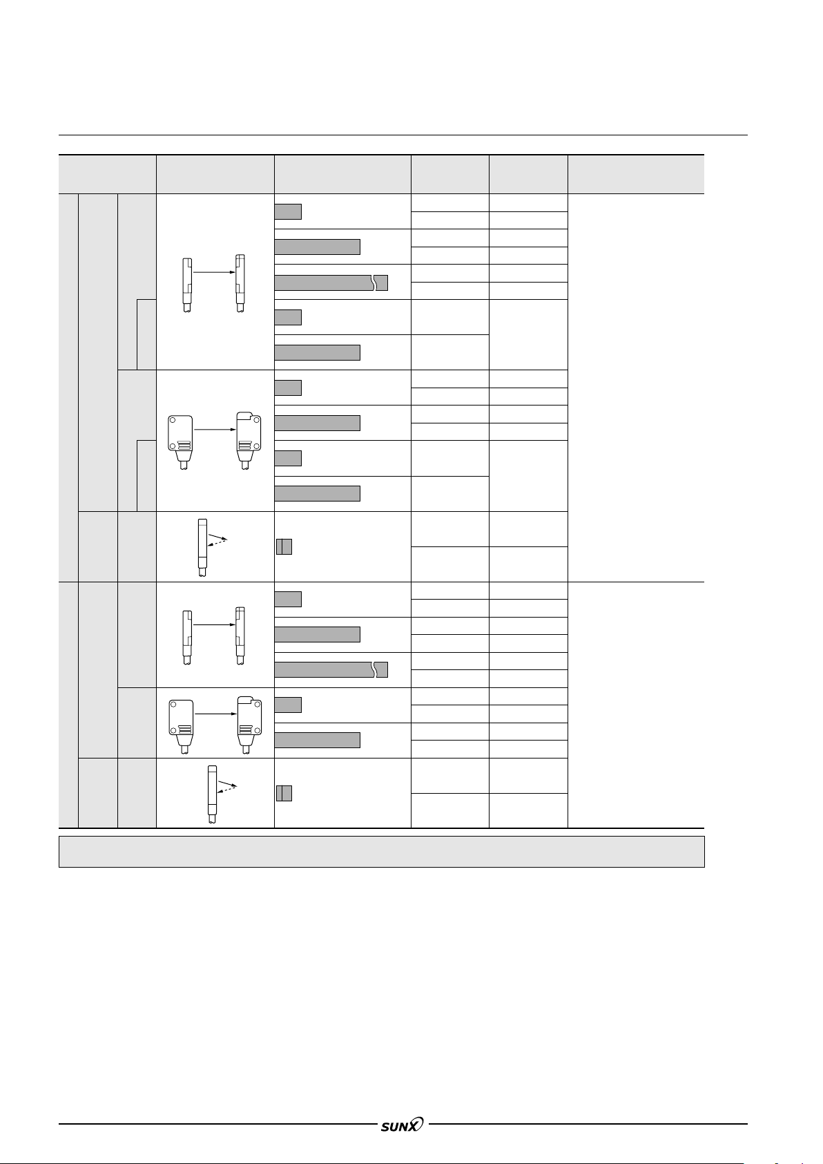
ORDER GUIDE
Type Appearance Sensing range Model No.
150 mm 5.906 in
500 mm
19.685 in
1 m
3.281 ft
Thru-beam
NPN output
Convergent
reflective
Thru-beam
PNP output
Front sensing
With operation mode
switch on the bifurcation
Side sensing
With operation mode
switch on the bifurcation
Front sensing
(Diffused beam type)
Front sensing
150 mm 5.906 in
500 mm
19.685 in
150 mm 5.906 in
500 mm
19.685 in
150 mm 5.906 in
500 mm
19.685 in
2 to 25 mm 0.079 to 0.984 in (Note)
(Convergent point: 10 mm 0.394 in)
150 mm 5.906 in
500 mm
19.685 in
1m
3.281 in
150 mm 5.906 in
500 mm
19.685 in
EX-11A
EX-11B
EX-13A
EX-13B
EX-19A
EX-19B
EX-15
EX-17
EX-11EA
EX-11EB
EX-13EA
EX-13EB
EX-15E
EX-17E
EX-14A
EX-14B
EX-11A-PN
EX-11B-PN
EX-13A-PN
EX-13B-PN
EX-19A-PN
EX-19B-PN
EX-11EA-PN
EX-11EB-PN
EX-13EA-PN
EX-13EB-PN
Output operation
Light-ON
Dark-ON
Light-ON
Dark-ON
Light-ON
Dark-ON
Switchable
either Light-ON
or Dark-ON
Light-ON
Dark-ON
Light-ON
Dark-ON
Switchable
either Light-ON
or Dark-ON
Light-ON
Dark-ON
Light-ON
Dark-ON
Light-ON
Dark-ON
Light-ON
Dark-ON
Light-ON
Dark-ON
Light-ON
Dark-ON
Output
NPN open-collector transistor
PNP open-collector transistor
Light-ON
Dark-ON
Convergent
Front sensing Side sensing
reflective
(Diffused beam type)
2 to 25 mm 0.079 to 0.984 in (Note)
(Convergent point: 10 mm 0.394 in)
EX-14A-PN
EX-14B-PN
NOTE: Mounting bracket is not supplied with the sensor. Please select from the range of optional sensor mounting
brackets (six types).
Note: The sensor does not detect even a specular background if it is separated by 100 mm 3.937 in or more. (However, the background should be
directly opposite.)
228
Page 4
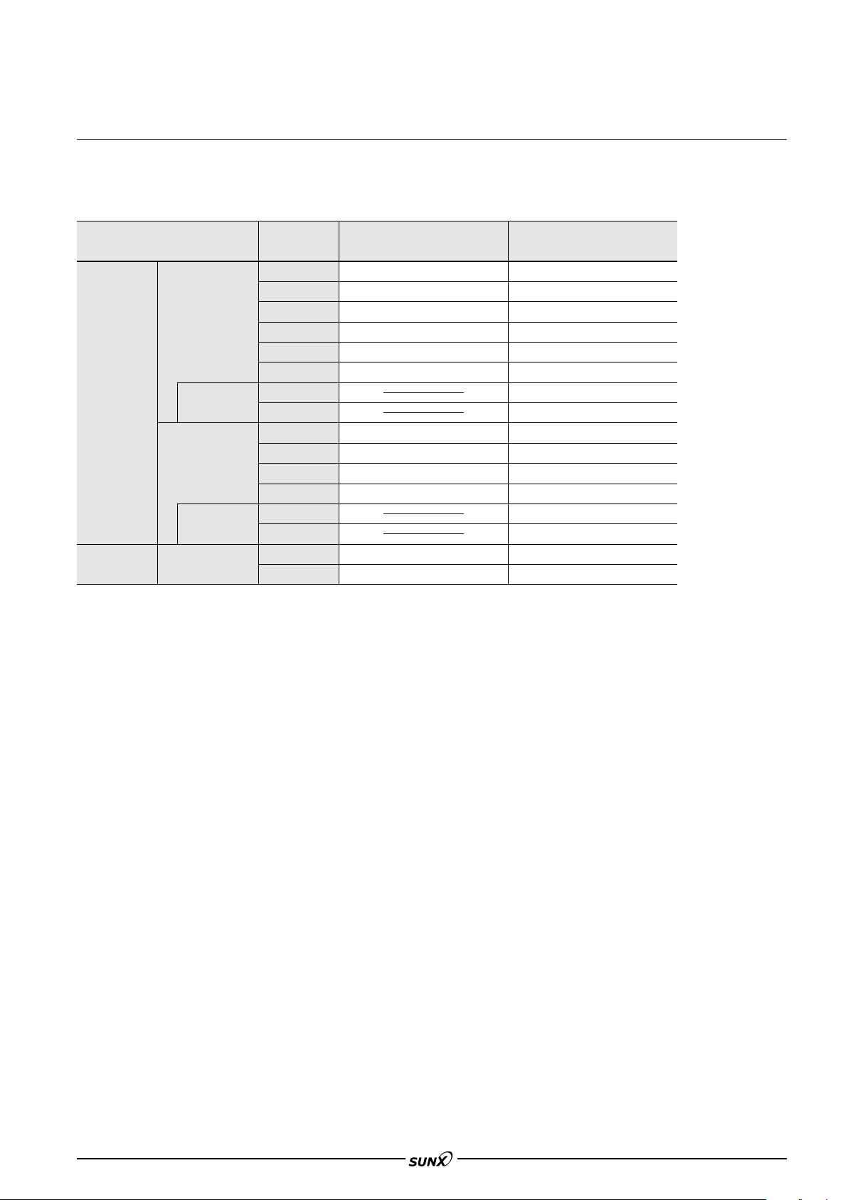
ORDER GUIDE
08/2005
Flexible cable type and 5 m 16.404 ft cable length type
Flexible cable type and 5 m 16.404 ft cable length type (standard: 2 m 6.562 ft) are also available.
• Table of model Nos.
Type Standard Flexible cable (2 m 6.562 ft) type 5 m 16.404 ft cable length type
EX-10
Front sensing
Thru-beam
Side sensing
Convergent
reflective
(Diffused beam type)
Front sensing
With operation
mode switch on
the bifurcation
With operation
mode switch on
the bifurcation
EX-11A
EX-11B
EX-13A
EX-13B
EX-19A
EX-19B
EX-15
EX-17
EX-11EA
EX-11EB
EX-13EA
EX-13EB
EX-15E
EX-17E
EX-14A
EX-14B
EX-11A-R
EX-11B-R
EX-13A-R
EX-13B-R
EX-19A-R
EX-19B-R
EX-11EA-R
EX-11EB-R
EX-13EA-R
EX-13EB-R
EX-14A-R
EX-14B-R
EX-11A-C5
EX-11B-C5
EX-13A-C5
EX-13B-C5
EX-19A-C5
EX-19B-C5
EX-15-C5
EX-17-C5
EX-11EA-C5
EX-11EB-C5
EX-13EA-C5
EX-13EB-C5
EX-15E-C5
EX-17E-C5
EX-14A-C5
EX-14B-C5
229
Page 5

EX-10
LEVEL
POWER
CHX-SC2
Sensor checker
08/2005
OPTIONS
Designation Model No. Description
Sensor mounting bracket
• MS-EX10-1 • MS-EX10-11
Sensor
mounting
bracket
Slit mask
Sensor checker
(Note)
Mounting screw
MS-EX10-1
MS-EX10-2
MS-EX10-3
MS-EX10-11
MS-EX10-12
MS-EX10-13
OS-EX10-12
(Slit size "1.2 mm "0.047 in)
OS-EX10-15
(Slit size "1.5 mm "0.059 in)
OS-EX10E-12
(Slit size "1.2 mm "0.047 in)
CHX-SC2
MS-M2
Mounting bracket for the front sensing type sensor [Cold rolled carbon steel (SPCC)]
(The thru-beam type sensor needs two brackets.)
Mounting bracket for the side sensing type sensor [Cold rolled carbon steel (SPCC)]
(The thru-beam type sensor needs two brackets.)
L-shaped mounting bracket sensor [Cold rolled carbon steel (SPCC)]
(The thru-beam type sensor needs two brackets.)
Mounting bracket for the front sensing type sensor [Stainless steel (SUS304)]
(The thru-beam type sensor needs two brackets.)
Mounting bracket for the side sensing type sensor [Stainless steel (SUS304)]
(The thru-beam type sensor needs two brackets.)
L-shaped mounting bracket [Stainless steel (SUS304)]
(The thru-beam type sensor needs two brackets.)
Slit on one side
Slit on both sides
Slit on one side
Slit on both sides
Slit on one side
Slit on both sides
It is useful for beam alignment of thru-beam type sensors.
The optimum receiver position is given by indicators, as
well as an audio signal.
Mounting screws with washers (50 pcs. lot). It can mount
securely as it is spring washer attached.
Sensing range: 600 mm 23.622 in [EX-19]
Min. sensing object:"2 mm "0.079 in
Sensing range: 400 mm 15.748 in [EX-19]
Min. sensing object:"1.2 mm "0.047 in
Sensing range: 800 mm 31.496 in [EX-19]
Min. sensing object:"2 mm "0.079 in
Sensing range: 500 mm 19.685 in [EX-19]
Min. sensing object:"1.5 mm
Sensing range: 250 mm 9.843 in [EX-13E, EX-17E]
Min. sensing object:"2 mm "0.079 in
Sensing range: 200 mm 7.874 in [EX-13E, EX-17E]
Min. sensing object:"1.2 mm "0.047 in
250 mm 9.843 in [EX-13, EX-17]
200 mm 7.874 in [EX-13, EX-17]
350 mm 13.780 in [EX-13]
300 mm 11.811 in [EX-13]
0.059 in
"
Material: Cold rolled carbon
Two M2 (length 4 mm 0.157 in)
pan head screws are attached.
• MS-EX10-2 • MS-EX10-12
Material: Cold rolled carbon
Two M2 (length 8 mm 0.315 in)
pan head screws are attached.
• MS-EX10-3 • MS-EX10-13
Material: Cold rolled carbon
Two M2 (length 4 mm 0.157 in)
pan head screws, and two
M2 (length 8 mm 0.315 in)
pan head screws are attached.
steel (SPCC)
(Uni-chrome plated)
steel (SPCC)
(Uni-chrome plated)
steel (SPCC)
(Uni-chrome plated)
Material: Stainless steel (SUS304)
Two M2 (length 4 mm 0.157 in)
pan head screws [stainless steel
(SUS304)] are attached.
Material: Stainless steel (SUS304)
Two M2 (length 8 mm 0.315 in)
pan head screws [stainless steel
(SUS304)] are attached.
Material: Stainless steel (SUS304)
Two M2 (length 4 mm 0.157 in)
pan head screws [stainless steel
(SUS304)] and two M2 (length
8 mm 0.315 in) pan head screws
[stainless steel (SUS304)] are
attached.
Slit mask
• OS-EX10-12 • OS-EX10E-12
• OS-EX10-15
Example of mounting
(OS-EX10E-12)
Tighten along with the sensor
mounting bracket.
Sensor checker
• CHX-SC2
230
Page 6
SPECIFICATIONS
08/2005
EX-10
Convergent reflective
(Diffused beam type)
Thru-beam • with operation mode switch on bifurcation
EX-15 EX-15E EX-17 EX-17E
(Note 2) (Note 2) (Note 2) (Note 2)
2 to 25 mm 0.079 to
0.984 in (Note 3)
(Conv. point: 10 mm 0.394 in)
"0.1 mm "0.004 in
copper wire
Setting distance:
()
10 mm 0.394 in
15 % or less of
operation distance
0.1 mm 0.004 in
or less
20 mA or less
150 mm 5.906 in 500 mm 19.685 in
"1 mm "0.039 in opaque object
Setting distance between
emitter and receiver:
()
150 mm 5.906 in
0.05 mm 0.002 in or less0.05 mm 0.002 in or less
30 mA or lessEmitter: 10 mA or less, Receiver: 15 mA or less
Type
Model
Light-ON
Item Dark-ON
Sensing range
Min. sensing object
Hysteresis
Repeatability
(perpendicular to sensing axis)
Supply voltage
Current consumption
No.
(Note 1)
Thru-beam
Front sensing Side sensing Front sensing Side sensing Front sensing Front sensing Front sensing Side sensing Front sensing Side sensing
EX-11A(-PN) EX-11EA(-PN) EX-13A(-PN) EX-13EA(-PN) EX-19A(-PN) EX-14A(-PN)
EX-11B(-PN) EX-11EB(-PN) EX-13B(-PN) EX-13EB(-PN) EX-19B(-PN) EX-14B(-PN)
150 mm 5.906 in
"1 mm "0.039 in opaque object
Setting distance between
emitter and receiver:
()
150 mm 5.906 in
500 mm 19.685 in 1 m 3.281 ft
"2 mm "0.079 in opaque object
Setting distance between
emitter and receiver:
()
500 mm 19.685 in
12 to 24 V DC10 % Ripple P-P 10 % or less
"2 mm "0.079 in
opaque object
Setting distance between
emitter and receiver:
()
1 m 3.281 ft
<NPN output type>
NPN open-collector transistor
• Maximum sink current: 50 mA
• Applied voltage: 30 V DC or less (between output and 0 V)
• Residual voltage: 1 V or less (at 50 mA sink current)
Output
Utilization category
Short-circuit protection
Response time
Operation indicator
Incident beam indicator
Stability indicator
Pollution degree
Protection
Ambient temperature
Ambient humidity
Ambient illuminance
EMC
Voltage withstandability
Insulation resistance
Environmental resistance
Vibration resistance
Shock resistance
Emitting element
Material
Cable (Note 4)
Cable extension
Weight
Accessories
Notes: 1) Model Nos. having the suffix ‘-PN’ are PNP output type.
Notes: 2) Either Light-ON or Dark-ON can be selected by the operation mode switch (located on the bifurcation).
Notes: 3) The sensing range of convergent reflective type sensor is specified for white non-glossy paper (50
The flexible cable type (model Nos. having suffix ‘-R’) has a 0.1 mm23-core (thru-beam type emitter : 2-core) flexible cabtyre cable, 2 m 6.562 ft long.
Notes: 4)
<PNP output type>
PNP open-collector transistor
• Maximum source current: 50 mA
• Applied voltage: 30 V DC or less (between output and
• Residual voltage: 1 V or less (at 50 mA source current)
Red LED (lights up when the output is ON)
Green LED (lights up under stable light received condition or
stable dark condition)
25 to55 C 13 to131 F (No dew condensation or icing allowed), Storage:30 to70 C 22 to158 F
Sunlight: 10,000 ?x at the light-receiving face, Incandescent light: 3,000 ?x at the light-receiving face
EN 50081-2, EN 50082-2, EN 60947-5-2
20 MΩ, or more, with 250 V DC megger between all supply terminals connected together and enclosure
10 to 500 Hz frequency, 3 mm 0.118 in amplitude in X, Y and Z directions for two hours each
Enclosure: Polyethylene terephthalate
Lens: Polyalylate
0.1 mm23-core (thru-beam type emitter: 2-core) cabtyre cable, 2 m 6.562 ft long
Extension up to total 50 m 164.042 ft is possible with 0.3 mm2, or more, cable
(thru-beam type: emitter and receiver).
Emitter: 20 g approx., Receiver: 20 g approx.
0.4 V or less (at 16 mA sink current)
V)
0.4 V or less (at 16 mA source current)
DC-12 or DC-13
Incorporated
0.5 ms or less
3 (Industrial environment)
IP67 (IEC)
35 to 85 % RH, Storage: 35 to 85 % RH
1,000 V AC for one min. between all supply terminals connected together and enclosure
2
acceleration (50 G approx.) in X, Y and Z directions for three times each
500 m/s
Red LED (modulated)
20 g approx.
Mounting screws: 1 set
Mounting screws:
NPN open-collector transistor
• Maximum sink current: 100 mA
• Applied voltage: 30 V DC or less
• Residual voltage: 1.5 V or less
• Residual voltage: 0.4 V or less
Orange LED (lights up when the output is ON),
located on the bifurcation
Red LED (lights up under light received condition),
located on the receiver
Green LED (lights up under stable light received condition
or stable dark condition), located on the receiver
Enclosure: Polyethylene terephthalate
Lens: Polyalylate, Bifurcation: Polyalylate
0.2 mm23-core cabtyre cable, 2 m 6.562 ft long (beyond bifurcation; from emitter / receiver to bifurcation: 0.5 m 1.640 ft long)
Extension up to total 100 m 328.084 ft is
possible with 0.3 mm
Mounting screws: 1 set, Adjusting screwdriver: 1 pc.
1 set
(between output and 0 V)
(at 100 mA sink current)
(at 16 mA sink current)
55 g approx.
50 mm 1.9691.969 in) as the object.
"2 mm "0.079 in opaque object
Setting distance between
emitter and receiver:
()
500 mm 19.685 in
2
, or more, cable.
231
Page 7
EX-10
Users’ circuitInternal circuit
Color code
50 mA max.
Sensor circuit
Tr
D
ZD
Load
(Brown)
V
(Black)
Output (Note)
(Blue) 0 V
12 to 24 V DC
10 %
Brown
Black (Note)
Blue
Load
12 to 24 V DC
10 %
Users’ circuitInternal circuit
D
50 mA max.
ZD
Tr
Load
(Black) Output (Note)
(Blue) 0 V
12 to 24 V DC
10 %
Sensor circuit
Color code
(Brown)
V
Users’ circuitInternal circuit
Color code
100 mA max.
Sensor circuit
Tr
D
ZD
Load
(Brown)
V
(Black) Output
(Blue) 0 V
12 to 24 V DC
10 %
12 to 24 V DC
10 %
Load
Brown
Black
Blue
Brown
Black (Note)
Blue
Load
12 to 24 V DC
10 %
08/2005
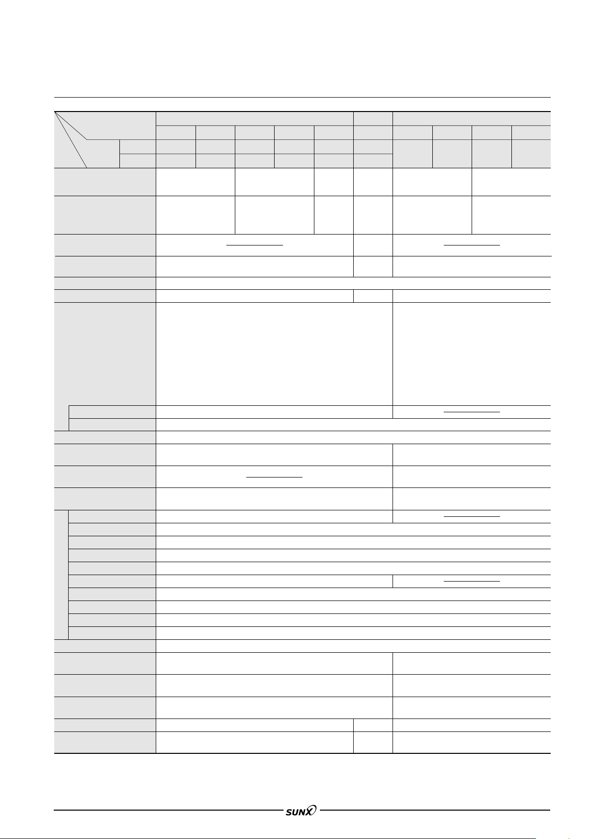
I/O CIRCUIT AND WIRING DIAGRAMS
EX-11 EX-13
EX-19 EX-14
I/O circuit diagram
Note:The emitter of the thru-beam type sensor does not
incorporate the output.
Symbols … D : Reverse supply polarity protection diode
D: Surge absorption zener diode
Z
Tr : NPN output transistor
EX-11-PN EX-13-PN
EX-19-PN EX-14-PN
NPN output type
Wiring diagram
Note:The emitter of the thru-beam type sensor does not
incorporate the black wire.
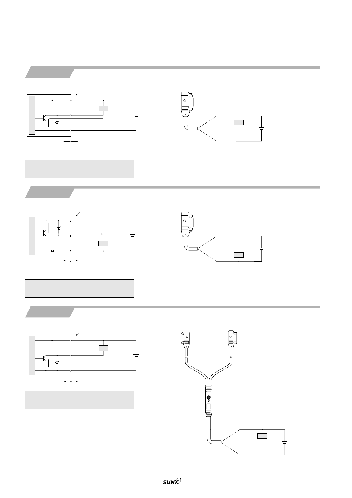
PNP output type
I/O circuit diagram Wiring diagram
Note: The emitter of the thru-beam type sensor does not
incorporate the output.
Symbols … D : Reverse supply polarity protection diode
EX-15 EX-15E
EX-17 EX-17E
D: Surge absorption zener diode
Z
Tr : PNP output transistor
NPN output type
I/O circuit diagram Wiring diagram
Symbols … D : Reverse supply polarity protection diode
232
D: Surge absorption zener diode
Z
Tr : NPN output transistor
Note: The emitter of the thru-beam type sensor does not
incorporate the black wire.
Page 8

SENSING CHARACTERISTICS (TYPICAL)
0 200
7.874
600
23.622
800
31.496
1,000
39.370
1
10
5
100
400
15.748
Excess gain
50
EX-13
EX-17
EX-11
EX-15
Setting distance L (mm in)
01
3.281
3
9.843413.123516.404
1
10
5
100
2
6.562
Excess gain
50
Setting distance L (m ft)
EX-19
200
7.874
100
3.937
0 100
3.937
200
7.874
0
500
19.685
1,000
39.370
Receiver
Emitter
L
#
Setting distance L (mm in)
Left
Right
Center
Operating point ?(mm in)
40 20 0 20 40
0
500
19.685
1,000
39.370
L
$
Receiver
Emitter
Setting distance L (mm in)
Left
Right
Center
Operating angle $( )
Receiver
Emitter
Receiver
100
3.937501.969
050
1.969
100
3.937
0
Left
Right
Center
Operating point ?(mm in)
200
7.874
100
3.937
150
5.906
EX-11
EX-15
EX-11
EX-15
EX-11E
EX-15E
EX-11E
EX-15E
L
#
L
#
Setting distance L (mm in)
Emitter
50
1.969
Emitter
Receiver
Emitter
Receiver
20 10 0 10 20
0
50
1.969
100
3.937
150
5.906
200
7.874
Left
Right
Center
Operating angle $( ° )
EX-11
EX-15
EX-11
EX-15
EX-11E
EX-15E
L
$
L
$
Setting distance L (mm in)
EX-11E
EX-15E
200
7.874
100
3.937
0 100
3.937
200
7.874
0
200
7.874
400
15.748
600
23.622
800
31.496
Slit on one side
Slit on both sides
Receiver
Emitter
L
#
Setting distance L (mm in)
Left
Right
Center
Operating point ?(mm in)
200
7.874
100
3.937
0 100
3.937
200
7.874
0
500
19.685
1,000
39.370
Slit on one side
Slit on both sides
Receiver
Emitter
L
#
Setting distance L (mm in)
Left
Right
Center
Operating point ?(mm in)
40
1.575200.787
020
0.787401.575
0
EX-13/17
Slit on one side
Receiver
Emitter
L
#
400
15.748
300
11.811
200
7.874
100
3.937
EX-13/17
Slit on both sides
EX-13E/17E
Slit on one side
EX-13E/17E
Slit on
both sides
Setting distance L (mm in)
Left
Right
Center
Operating point ?(mm in)
100
3.937501.969
050
1.969
100
3.937
0
Slit on one side
or both sides
Slit on one side,
sensing range: 350 mm 13.78 in
Slit on both sides,
sensing range: 300 mm 11.81 in
Receiver
Emitter
L
#
400
15.748
300
11.811
200
7.874
100
3.937
Setting distance L (mm in)
Left
Right
Center
Operating point ?(mm in)
Emitter
Receiver
Emitter
Receiver
100
3.937501.969
050
1.969
100
3.937
0
Left
Right
Center
Operating point ?(mm in)
200
7.874
400
15.748
600
23.622
800
31.496
EX-13
EX-17
EX-13
EX-17
EX-13E
EX-17E
EX-13E
EX-17E
L
#
L
#
Setting distance L (mm in)
Emitter
Receiver
Receiver
20 10 0 10 20
Left
Right
Center
Operating angle $( ° )
EX-13
EX-17
L
$
L
$
Emitter
EX-13
EX-17
0
200
7.874
400
15.748
600
23.622
800
31.496
EX-13E
EX-17E
EX-13E
EX-17E
Setting distance L (mm in)
08/2005
EX-10
All models
Thru-beam type
Correlation between setting distance and excess gain
EX-11 EX-11E
EX-15 EX-15E
Thru-beam type
Parallel deviation Angular deviation
EX-13 EX-13E
EX-17 EX-17E
Parallel deviation Angular deviation
EX-19
Parallel deviation Angular deviation
Thru-beam type
Thru-beam type
Parallel deviation with slit masks ("1.2 mm "0.047 in) Parallel deviation with slit masks ("1.5 mm "0.059 in)
Parallel deviation with slit masks ("1.2 mm "0.047 in) Parallel deviation with slit masks ("1.5 mm "0.059 in)
233
Page 9
EX-10
Operation mode switch
L : Light-ON
D: Dark-ON
Lights up when the output is
ON.
Operation indicator (Orange)
5
0.197
10
0.394
05
0.197100.394
0
10
0.394
20
0.787
30
1.181
40
1.575
White
N4
7 mm
0.276 in
#
L
Setting distance L (mm in)
Left
Right
Center
Operating point ?(mm in)
5050 mm 1.9691.969 in
Non-glossy paper
0
10
0.394
20
0.787
30
1.181
40
1.575
N2 N4 N6 N8
Lightness LightDark
N2N1 N3 N4 N5 N6 N7 N8 N9
Sensing range L (mm in)
Sensing region
Distance to
convergent point
0
20
0.787
10
0.394
40
1.575
60
2.362
80
3.150
Sensing range L (mm in)
Black circuit board
Black rubber sheet
IC tray (Black)
Glass epoxy printed circuit board
(Green masked surface)
Ceramic circuit board
White non-glossy paper
Stainless steel plate
Aluminum plate
(Hair line)
Aluminum-evaporated mirror
Distance to convergent point
5
0.197
10
0.394
05
0.197100.394
0
10
0.394
20
0.787
30
1.181
40
1.575
White
N4
#
7.75
mm
0.305 in
L
Setting distance L (mm in)
Down
Up
Center
Operating point ?(mm in)
5050 mm
1.9691.969 in
Non-glossy paper
M20.4 0.016 hole
tapped, 6 0.157 deep
Attached
screw
[M2 (length 10 0.394)]
11
0.433
Sensing
direction
Sensing
direction
M20.4 0.016 hole
tapped, 7 0.276 deep
[M2 (length 8 0.315)]
Attached
screw
11
0.433
Thickness of
mounting plate: 2 0.079 or less
Attached
screw
[M2 (length 10 0.394)]
Thickness of
mounting plate: 2.5 0.098 or less
Spring
washers
Nuts
Flat washers
[M2 (length 8 0.315)]
Attached
screw
Sensing
direction
Sensing
direction
11
0.433
11
0.433
08/2005
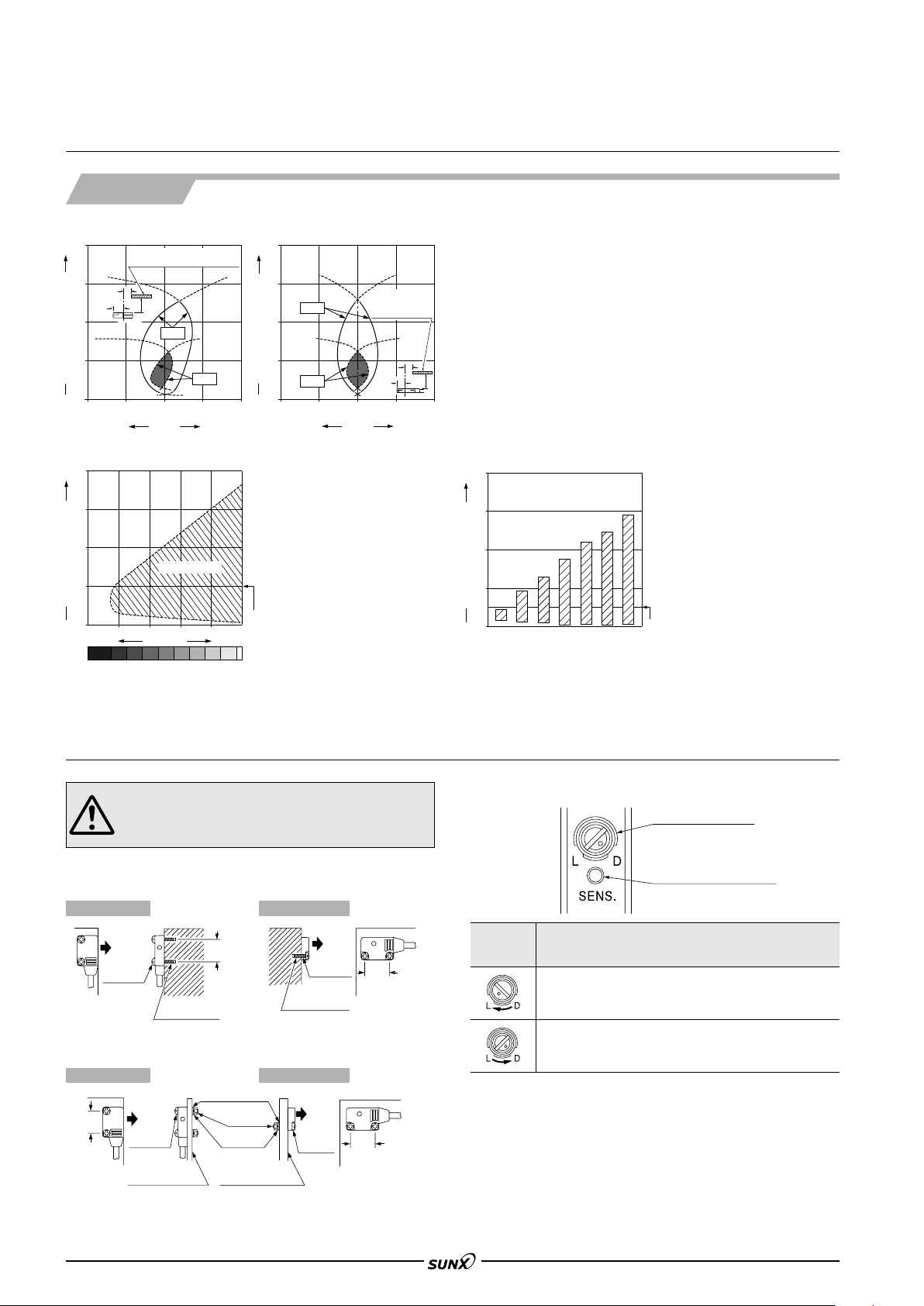
SENSING CHARACTERISTICS (TYPICAL)
EX-14
Convergent reflective type
Sensing fields
•
Horizontal (left and right) direction
• Vertical (up and down) direction
Correlation between lightness and sensing range
The sensing region is represented by oblique lines in the left
figure. However, the sensitivity
should be set with enough margin because of slight variation in
products.
Lightness shown on the left
may differ slightly from the
()
actual object condition.
Correlation between material (5050 mm 1.9691.969 in) and sensing range
The bars in the graph indicate the
sensing range for the respective
material. However, there is a
slight variation in the sensing
range depending on the product.
Further, if there is a reflective
object (conveyor, etc.) in the
background of the sensing object,
since it affects the sensing,
separate it by more than twice the
sensing range shown in the left
graph.
PRECAUTIONS FOR PROPER USE
Mounting
• In case of mounting on tapped holes (Unit: mm in)
The tightening torque should be 0.2 N m or less.
•
The tightening torque should be 0.2 N m or less.
234
This product is not a safety sensor. Its use is not
intended or designed to protect life and prevent body
injury or property damage from dangerous parts of
machinery. It is a normal object detection sensor.
Side sensing
Front sensing
In case of using attached screws and nuts (Unit: mm in)
Side sensing Front sensing
Operation mode switch (EX-15, EX-15E, EX-17 and EX-17E only)
Switch
position
Light-ON mode is set when the switch is turned fully
clockwise (L side).
Dark-ON mode is set when the switch is turned fully
counterclockwise (D side).
Description
Others
• Do not use during the initial transient time (50ms)
(EX-15, EX-15E, EX-17, EX-17E: 100 ms) after
the power supply is switched on.
Page 10

2-"2.2 "0.087
mounting holes
Beamemitting
part
11
0.433
1.75 0.069
4.5
0.177
14.5
0.571
5.5
0.217
10
0.394
1.75 0.069
2.1
0.083
3.5
0.138
"2.5 "0.098 cable, 2 m 6.562 ft long
6.5
0.256
4
0.157
2.1
0.083
4
0.157
3.5
0.138
5.5
0.217
10
0.394
6.45
0.254
Beamreceiving
part
2-"2.2 "0.087
mounting holes
"2.5 "0.098 cable, 2 m 6.562 ft long
11
0.433
1.75
0.069
4.5
0.177
14.5
0.571
1.5
0.059
6.5
0.256
Stability
indicator
(Green)
Operation
indicator
(Red)
1.75
0.069
2-"2.2 "0.087
mounting holes
"2.5 "0.098 cable, 2 m 6.562 ft long
11
0.433
1.75 0.069
4.5
0.177
14.5
0.571
10
0.394
1.75 0.069
6.5
0.256
4
0.157
Beamemitting
part
4.5
0.177
2.25
0.089
4.2
0.165
Stability
indicator (Green)
Operation
indicator (Red)
Beamreceiving
part
4.5
0.177
2.25
0.089
4.2
0.165
4
0.157
10
0.394
6.45
0.254
1.75
0.069
2-"2.2 "0.087
mounting holes
"2.5 "0.098 cable, 2 m 6.562 ft long
11
0.433
1.75
0.069
4.5
0.177
14.5
0.571
1.5
0.059
6.5
0.256
500
19.685
2.1
0.083
3.5
0.138
38
1.496
15.2 0.598
8
0.315
7
0.276
1 0.039
1.75
0.069
5.5
0.217
4
0.157
4.5
0.177
1.5
0.059
19.2
0.756
11
0.433
1.75
0.069
6.45 0.254
Beamreceiving
part
Incident beam indicator (Red)
Stability indicator (Green)
5.5
0.217
1.75
0.069
11
0.433
4
0.157
10
0.394
10 0.394
1.75
0.069
2-"2.2 "0.087
mounting holes
"2.5 "0.098 cables
Operation mode switch
Operation indicator
(Orange)
2-"2.2 "0.087
mounting holes
Beamemitting
part
2.1
0.083
3.5
0.138
"3.8 "0.150 cable,
2 m 6.562 ft long
14.5
0.571
4.5
0.177
14.5
0.571
Operation mode switch
500
19.685
38
1.496
15.2 0.598
8
0.315
7
0.276
1 0.039
19.2
0.756
Beamemitting
part
4
0.157
11
0.433
1.75
0.069
1.75
0.069
10
0.394
6.45
0.254
4.2
0.165
1.75
0.069
4.2
0.165
2.25
0.089
4.5
0.177
4.5
0.177
14.5
0.571
11
0.433
1.75
0.069
4
0.157
10
0.394
1.5
0.059
14.5
0.571
4.5
0.177
Operation indicator
(Orange)
"2.5 "0.098 cables
2-"2.2 "0.087
mounting holes
Beamreceiving
part
Stability indicator (Green)
Incident beam indicator (Red)
2-"2.2 "0.087
mounting holes
2.25
0.089
4.5
0.177
"3.8 "0.150 cable,
2 m 6.562 ft long
DIMENSIONS (Unit: mm in)
08/2005
EX-10
EX-11A EX-11B EX-13A
EX-13B EX-19A EX-19B
EX-11EA EX-11EB
EX-13EA EX-13EB
Sensor
Emitter Receiver
Sensor
EX-15
EX-17
Sensor
Emitter EmitterReceiver Receiver
Emitter Receiver
EX-15E
EX-17E
Sensor
235
Page 11

EX-10
Stability indicator
(Green)
Operation
indicator (Red)
1.75
0.069
2.75
0.108
6.45
0.254
13
0.512
2.1
0.083
3.5
0.138
4.5
0.177
Beamreceiving
part
Beam-emitting part
2-
"2.2 "0.087 mounting holes
"2.5 "0.098 cable,
2 m 6.562 ft long
4.5
0.177
14.5
0.571
11
0.433
1.5
0.059
1.75
0.069
8
0.315
5
0.197
4-M20.4 0.016
thru-hole threads
2-"3.4 "0.134 mounting holes
6.5
0.256
11
0.433
15
0.591
8
0.315
7.6
0.299
3.5
0.138
20
0.787
8
0.315
3.7
0.146
t 1.2
t 0.047
Beamemitting
part
Beamreceiving
part
3
0.118
5
0.197
10.75
0.423
4.25
0.167
1.25
0.049
t 1.2
t 0.047
3.7
0.146
3.5
0.138
20 0.787
13
0.512
22.75 0.896
7.6
0.299
(0.7)
(0.028)
(
4.9)
(0.193)
3.5
0.138
8
0.315
(8.8)
(0.346)
15
0.591
11
0.433
8
0.315
2-"3.4 "0.134 mounting holes
2-M20.4 0.016
thru-hole threads
t 1.2
t 0.047
15
0.591
11
0.433
20
0.787
6.25
0.246
8
0.315
3.5
0.138
8
0.315
1.4
0.055
3.2
0.126
7.6
0.299
10
0.394
7.6
0.299
3.2
0.126
0.25
0.010
4.25
0.167
1.4
0.055
1.25
0.049
2.5 0.098
t 1.2
t 0.047
6.25
0.246
4.5
0.177
(1.3)
(0.051)
11
0.433
15
0.591
8
0.315
8
0.315
3.5
0.138
20
0.787
Beamreceiving
part
4
0.157
(7.45)
(0.293)
(2.3)
(0.091)
08/2005
DIMENSIONS (Unit: mm in)
EX-14A
EX-14B
MS-EX10-1
Sensor
Sensor mounting bracket (Optional)
Assembly dimensions
Mounting drawing with EX-14
236
Material: Cold rolled carbon steel (SPCC)
(Uni-chrome plated)
Two M2 (length 4 mm 0.157 in) pan head screws are attached.
MS-EX10-2
Sensor mounting bracket (Optional)
Material: Cold rolled carbon steel (SPCC)
Two M2 (length 8 mm 0.315 in) pan head
screws are attached.
(Uni-chrome plated)
Assembly dimensions
Mounting drawing with EX-11E and EX-13E
Page 12

DIMENSIONS (Unit: mm in)
4-M20.4 0.016
thru-hole threads
2
0.079
6.5
0.256
3.2
0.126
8
0.315
10.8
0.425
7 0.276
10.5
0.413
1.4
0.055
11
0.433
15
0.591
t 1.2
t 0.047
Beamreceiving part
Beamemitting part
(2.75)
(0.108)
10.8
0.425
t 1.2
t 0.047
(0.7)
(0.028)
13
0.512
5
0.197
1.75 0.069
1.25
0.049
3
0.118
11
0.438
15
0.591
4.25
0.167
3.5
0.138
10.5
0.413
3.2
0.126
1.4
0.055
8
0.315
6.25
0.246
7
0.276
4-M20.4 0.016
thru-hole threads
11
0.433
3.2
0.126
1.4
0.055
3.2
0.126
1.4
0.055
15
0.591
20
0.787
6.5
0.256
3.5
0.138
8
0.315
8
0.315
8.1
0.319
t 1.2
t 0.047
3.7
0.146
11
0.433
3.2
0.126
1.4
0.055
3.2
0.126
1.25
0.049
4.25
0.167
1.4
0.055
15
0.591
22.75
0.896
3.5
0.138
8
0.315
3
0.118
8.1
0.319
20
0.787
t 1.2
t 0.047
3.7
0.146
3.5
0.138
(4.9)
(0.193)
(0.7)
(0.028)
13
0.512
5
0.197
10.75 0.423
Beam-emitting part
Beam-receiving part
(9.3)
(0.366)
8 0.315
2-M20.4 0.016
thru-hole threads
11
0.433
3.2
0.126
1.4
0.055
3.2
0.126
1.4
0.055
15
0.591
6.25
0.246
20
0.787
8
0.315
8.1
0.319
t 1.2
t 0.047
8
0.315
3.5
0.138
15
0.591110.433
4
0.157
3.5
0.138
3.2
0.126
2.5
0.098
8.1
0.319
20
0.787
(7.45)
(0.293)
(2.3)
(0.091)
6.25
0.246
4.5
0.177
t 1.2
t 0.047
(1.3)
(0.051)
Beamreceiving
part
8
0.315
10
0.394
8
0.315
0.25
0.010
1.4
0.055
1.25
0.049
3.2
0.126
1.4
0.055
4.25
0.167
08/2005
EX-10
MS-EX10-3
Material: Cold rolled carbon steel (SPCC)
(Uni-chrome plated)
Two M2 (length 4 mm 0.157 in) pan head screws, and two M2
(length 8 mm 0.315 in) pan head screws are attached.
MS-EX10-11
Sensor mounting bracket (Optional)
Sensor mounting bracket (Optional)
Assembly dimensions
Mounting drawing with EX-14
Assembly dimensions
Mounting drawing with EX-14
Material: Stainless steel (SUS304)
Two M2 (length 4 mm 0.157 in) pan head screws [stainless steel (SUS304)] are
attached.
MS-EX10-12
Material: Stainless steel (SUS304)
Two M2 (length 8 mm 0.315 in) pan head screws [stainless steel (SUS304)] are
attached.
Sensor mounting bracket (Optional)
Assembly dimensions
Mounting drawing with EX-11E and EX-13E
237
Page 13

EX-10
4-M20.4 0.016
thru-hole threads
t 1.2
t 0.047
10.8
0.425
11
0.433
10.5
0.413
6.5 0.256
3.2 0.126
2
0.079
15
0.591
7
0.276
1.4
0.055
1.4 0.055
8
0.315
3.2 0.126
11
0.433
3.2
0.126
1.25
0.049
4.25
0.167
15
0.591
8
0.315
3
0.118
3.2
0.126
1.4
0.055
13
0.512
10.5
0.413
3.5
0.138
1.75
0.069
10.8
0.425
5
0.197
1.4
0.055
Beam-emitting
part
Beam-receiving
part
t 1.2
t 0.047
(2.75)
(0.108)
(0.7)
(0.028)
6.25
0.246
7
0.276
08/2005
DIMENSIONS (Unit: mm in)
MS-EX10-13
Material: Stainless steel (SUS304)
Two M2 (length 4 mm 0.157 in) pan
head screws [stainless steel (SUS304)]
and two M2 (length 8 mm 0.315 in) pan
head screws [stainless steel (SUS304)]
are attached.
Sensor mounting bracket (Optional)
Assembly dimensions
Mounting drawing with EX-14
238
 Loading...