

Page 1
Rotary Potentiometers/EVJC/EVJY
12 mm Squa re Two-in-One
Rotary Potentiometers (Dual Type)
Type:
EVJC/EVJY
■ Features
● Rectangular-shaped, automatic mounting type
● High tactile feedback
● Available for automatic dip soldering (Flux-proof
struc ture)
● Highly reliable and dust-proof
Explanation of Part Numbers
■
1
E
2
V
Product Code Specifications Shaft Trims & Dimensions Taper & Resistance
3
J
4 5 6 7 8 9 10 11 12
C
Y
Japan
Malaysia
■ Recommended Ap pli ca tions
● Audio Equipment
● Video Equipment
● Electronic Musical Instruments
■ Product Chart
Installation direction
Horizontal
Vertical
Style
Without bushing
With bushing
With sleeve
Without bushing —
With bushing —
With sleeve —
Height
(H=mm)
10.0
12.5
10.0
12.5
10.0
12.5
Applications Detent Type
Volu me co ntro l Wi thout detent EVJC00
Ton e c on tr ol
Volu me co ntro l Wi thout detent EVJC90
Ton e c on tr ol
Volu me co ntro l Wi thout detent EVJC20
Ton e c on tr ol
Volu me co ntro l Wi thout detent EVJCB0
Ton e c on tr ol
Volu me co ntro l Wi thout detent EVJC25
Ton e c on tr ol
Volu me co ntro l Wi thout detent EVJCB5
Ton e c on tr ol
Volu me co ntro l Wi thout detent E VJY00
Ton e c on tr ol
Volu me co ntro l Wi thout detent EVJY10
Ton e c on tr ol
Volu me co ntro l Wi thout detent EVJY15
Ton e c on tr ol
Without detent EVJC30
Midpoint EVJC31
Without detent EVJC40
Midpoint EVJC41
Without detent EVJC50
Midpoint EVJC51
Without detent EVJCH0
Midpoint EVJCH1
Without detent EVJC55
Midpoint EVJC56
Without detent EVJCH5
Midpoint EVJCH6
Without detent EVJY80
Midpoint EVJY81
Without detent EVJY90
Midpoint EVJY91
Without detent EVJY95
Midpoint EVJY96
Design and specifi cations are each subject to change without notice. Ask factory for the current technical specifi cations before purchase and/or use.
Should a safety concern arise regarding this product, please be sure to contact us immediately.
Oct. 2005
Page 2
Rotary Potentiometers/EVJC/EVJY
■ Specifi cations
Classifi cation Item
Applications 12 mm square Two-in-One
Rotation Angle 3 00 °
Rotation Torque 2 mN·m to 20 mN·m
Me chan i cal
Spec i fi ca tio ns
Shaft Stopper Strength 0.5 N·m min.
Shaft Pull/Push Strength 80 N min.
Shaft Inclination
(Measured at the top of the shaft)
Bushing-Nut Tightening Torque
0.35 mm max.
1 N·m max.
Nominal Total Resistance 5 k to 500 k (Tolerance ±20 %)
Taper A, B, C, D, G, BH
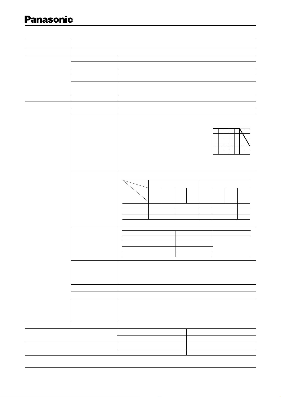
0.05 W (0 °C to 50 °C)
For potentiometers operating in am bi ent
Power Rating
temperatures above 50 °C, Rating
should be derated in ac cor dance with
the fi g ure on the right.
Power Derating Curve
100
80
60
40
33
20
Rated Load(%)
020406070
Ambient Temperature(°C)
Electrical
Specifi cations
pe
Ty
For genera l purpose (t one) For volume c ontrol
Taper &
Terminal
A, B, D, G
1 to 2
25 max. 25 max.
25 max. 50 max.
100 max. 100 max.
Residual Resistance
Nominal
Total
Resistance
5 k < R < 50 k
50 k < R < 250 k
250 k < R < 500 k
Nominal total resistance Max. Attenuation Insertion loss
Maximum Attenuation
(for volume control,
taper A, B, D)
5 k < R < 10 k
10 k < R < 50 k
50 k < R < 100 k
100 k < R –92 dB max.
For volume control within
Tracking
±3 dB at –40 to 0 dB
For Tone control within
±3 dB at midpoint
Insulation Resistance 100 M min. at 250 Vdc
Dielectric Withstand Voltage
Noise Level
300 Vac for 1 minute
47 mV max.
Apply 20 V (When Voltage Rating < 20 V, use the rated volt age.)
Rotate shaft at 30 r/min.
B, C, G
2 to 3
A, D
2 to 3C1 to 2
–65 dB max.
–72 dB max.
–82 dB max.
A, B, D
1 to 2
15 max.
15 max.
50 max.
A, B, D
2 to 3C1 to 2C2 to 3
25 max.
50 max.
100 max.
20 max.
20 max.
50 max.
0.1 dB max.
Endurance Operating Life ✽115000 cycles min.
Minimum Quantity/Packing Unit ✽2
Packing Unit ✽2
1 : No direct current should be applied.
✽
2 : With bushing : L=L+7.5 mm
✽
Design and specifi cations are each subject to change without notice. Ask factory for the current technical specifi cations before purchase and/or use.
Should a safety concern arise regarding this product, please be sure to contact us immediately.
80 pcs. (Tray Pack) L<20.0 mm
60 pcs. (Tray Pack) L>20.0 mm
800 pcs. L<20.0 mm
600 pcs. L>20.0 mm
Dec. 2005
Page 3

Rotary Potentiometers/EVJC/EVJY
■ Dimensions in mm (not to scale)
for Volume :
for Tone :
Horizontal, without Bushing
●
No. 1
..........................................................................................
14.2±1.0
12.1±1.0
11.0
3
5-2.0
11.0±1.0
14.0±0.7
0
˚±5˚
6.5
6.8
(5.0)
(5.5)
8.7
0.6±0.1
(0.3)
(1.3)
(f 7.0)
(3.5)
0.3±0.1
(0.4)
5.2
(6.0)
H
(3.6)
2.0
3.3
6.7
L
(2.5)
EVJC00, EVJC90
EVJC30, EVJC40
EVJC31, EVJC41
2.0
12.2±0.1
5-2.0
6-f 0.8
Recommended PWBpiercing plan
(Pitch tolerance:±0.1)
View frommounting side
0
+0.1
2.1
+0.1
0
(without de tent)
(with detent)
3.3
for Volume :
for Tone :
Horizontal, with Bushing
●
No. 2
...............................................................................................
M9 P=0.75
14.2±1.0
12.1±1.0
11.0
8.0±0.2
30 ˚
±
5
2.0
˚
6.8
6.5
8.0±0.2
5-2.0
11.0±1.0
14.0±0.7
(5.5)
2.0
8.7
0.6±0.1
Mounting surface
L
0.8
(3.5)
0.3±0.1
6.0
(0.4)
(6.0)
H
(3.6)
2.0
3.3
(2.5)
7.5
for Volume :
for Tone :
Horizontal, with Sleeve
●
..................................................................................................
No. 3
f 9.0
14.2±1.0
12.1±1.0
11.0
8.0±0.2
3
0 °
±
5
2.0
°
6.8
6.5
8.0±0.2
2-5.0
11.0±1.0
14.0±0.7
(5.5)
2.0
8.7
0.6±0.1
L
0.8
(3.5)
0.3±0.1
6.0
7.5
3.3
Side A
(0.4)
2.0
(2.5)
(6.0)
H
(3.6)
EVJC20, EVJCB0
EVJC50, EVJCH0
EVJC51, EVJCH1
12.2±0.1
5-2.0
+0.1
6-f 0.8
Recommended PWBpiercing plan
(Pitch tolerance:±0.1)
View frommounting side
2.0
0
Mounting surface
(without de tent)
0
+0.1
2.1
EVJC25, EVJCB5
EVJC55, EVJCH5
EVJC56, EVJCH6
2.0
12.2±0.1
5-2.0
+0.1
6-f 0.8
0
Recommended PWBpiercing plan
(Pitch tolerance:±0.1)
View frommounting side
(without de tent)
0
+0.1
2.1
3.3
7.5
side A
(with detent)
3.3
7.5
(with detent)
for Volume :
for Tone :
Vertical, without Bushing
●
..............................................................................................................
EVJY00
EVJY80
EVJY81
No. 4
(3.6)
L
12.1±1.0
11.0
30
°±
5 °
6.8
6.5
(5.5)
(5.5)
8.7
0.6±0.1
2-5.0
13.0
Design and specifi cations are each subject to change without notice. Ask factory for the current technical specifi cations before purchase and/or use.
Should a safety concern arise regarding this product, please be sure to contact us immediately.
(1.3)
0.3
(0.3)
6.7
5.2
(3.2)
13.8±1.0
0
+0.1
13.0±0.5
2.0
11.0
0. 0.1
2.0
2.1
+0.1
6-f 0.8
11.0±0.1
5-2.0
0
Recommended PWBpiercing plan
(Pitch tolerance:±0.1)
View frommounting side
(without de tent)
(with detent)
Mar. 2005
Page 4

Rotary Potentiometers/EVJC/EVJY
11.0±0.1
13.0±0.1
2.0
5-2.0
Recommended PWB piercing plan
(Pitch tolerance: ±0.1)
View from mounting side
2.0
2.0
12.1±1.0
11.0
13.0±0.5
8.0±0.5
8.0±0.5
6.5
6.88.7
(5.5)
(5.5)
L7.5
(3.6)
f9.0
30 ˚±5˚
6-f0.8
+
0.1
0
2.1
+
0.1
0
6.0
2.0
0.3±0.1
11.0
0.8
(3.2)
for Volume :
for Tone :
Vertical, with Bushing
●
No. 5
...................................................................................................................
(3.6)
7.5
6.0
0.8
0.5
±
2.0
(3.2)(0.3)
0.1
±
0.3
13.8±1.0
11.0
Recommended PWBpiercing plan
M9, P=0.75
0.2
±
8.0
12.1±1.0
11.0
8.0±0.2
2-5.0
13.0
L
30 ˚
±
5˚
6.8
6.5
(5.5)
(5.5)
8.7
0.6±0.1
Mounting surface
11.0±0.1
for Volume :
for Tone :
Vertical, with Sleeve
●
......................................................................................................................
No. 6
EVJY10
EVJY90
EVJY91
0
13.0±0.1
+0.1
2.1
(Pitch tolerance:±0.1)
View frommounting side
(without detent)
2.0
6-f 0.8
5-2.0
EVJY15
EVJY95
EVJY96
(without detent)
(with detent)
+0.1
0
(with detent)
Design and specifi cations are each subject to change without notice. Ask factory for the current technical specifi cations before purchase and/or use.
Should a safety concern arise regarding this product, please be sure to contact us immediately.
Nov. 2005
Page 5

2
3
1
3
2
1
1
21
23
3
■ Circuit Diagram and PWB Pierc ing Plan
Vol ume con tro l without tap With tap Tone control
3
Rotary Potentiometers/EVJC/EVJY
3
2
2
Relation of
mounting holes
and terminals
1
21
1
1
23
3
————
Notes:
1. I=Resistor 1, II=Resistor 2
2. Relation of mounting holes and terminals. Refer to each pierc ing plan for dimensions.
3. View from mounted part side.
■ Shaft Trims and Dimensions in mm
Dimensions Trim Position
k
1
Note: The drawing at full CCW position
0
–0.1
0
–0.1
6.0
f
4.5
C
3
0
Terminal side
Dimensions in mm
Style
Shaft
L
m
1
Corner cut
Bushing, Sleeve
m
2
15.0 4.5C0.5 —
20.0 7.0 C1.0 —
25.0 12.0 C1.0 —
30.0 12.0 C1.0 —
15.0 4.5C0.5 —
20.0 7.0 C1.0 —
25.0 12.0 C1.0 —
without
Bushing
Horizontal
Vertical
6.7
6.7
L
L
30.0 12.0 C1.0 —
12.5 7.0 C1.0 5.0
15.0 7 .0 C1.0 5.0
Horizontal
with
Bushing
or
with
7.5
k
2
L
Sleeve
Vertical
7.5
2
k
L
17.5 12.0 C1.0 5.0
20.0 12.0 C1.0 5.0, 7.0
22.5 12.0 C1.0 5.0, 7.0
12.5 7.0 C1.0 5.0
15.0 7 .0 C1.0 5.0
17.5 12.0 C1.0 5.0
20.0 12.0 C1.0 5.0, 7.0
22.5 12.0 C1.0 5.0, 7.0
Design and specifi cations are each subject to change without notice. Ask factory for the current technical specifi cations before purchase and/or use.
Should a safety concern arise regarding this product, please be sure to contact us immediately.
Mar. 2005
 Loading...