

Panasonic EQ-34, EQ-34-PN, EQ-34W Instruction Manual
Thank you very much for purchasing Panasonic
p
roducts. Please read this Instruction Manual
carefully and thoroughly for the correct and
optimum use of this product. Kindly keep this
manual in a convenient place for quick reference
.
CAUTIONS
3
●
●
●
●
●
●
●
●
●
●
●
●
●
●
●
●
This product has been developed / produced for
industrial use only.
Make sure that the power supply is OFF while wiring.
Take care that wrong wiring will damage the sensor.
Verify that the supply voltage variation is within
the rating.
If power is supplied from a commercial switching regulator, ensure that the frame ground
(F.G.) terminal of the power supply is connected to an actual ground.
In case noise generating equipment (switching
regulator, inverter motor, etc.) is used in the vicinity of this product, connect the frame ground (F.G.)
terminal of the equipment to an actual ground.
Do not run the wires together with high-voltage
lines or power lines or put them in the same raceway. This can cause malfunction due to induction.
Extension up to total 100m, is possible with
0.3mm2, or more, cable. However, in order to reduce noise, make the wiring as short as possible.
Do not use during the initial transient time
(50ms) after the power supply is switched on.
Take care that the sensor is not directly exposed
to fluorescent lamp from a rapid-starter lamp, a
high frequency lighting device or sunlight etc., as
it may affect the sensing performance.
Avoid dust, dirt, and steam. Do not use it in places having excessive vapor, dust, etc., or where
it may come in direct contact with corrosive gas.
Take care that the sensor does not come in contact with water, oil, grease, organic solvents, such
as, thinner etc., strong acid or alkaline.
This sensor is suitable for indoor use only.
Make sure that stress by forcible bend or pulling
is not applied directly to the sensor cable joint.
Since the cable end is not waterproof, do not
use the sensor in the application where water
may seep in from the cable end.
When connecting the mating cable to the connector type sensor, the tightening torque should
be 0.4N・m or less.
SPECIFICATIONS
1
NPN open-collector transistor
・Maximum sink current: 100mA
・Applied voltage: 30V DC or less
(between output and 0V)
・Residual voltage: 1V or less
(at 100mA sink current)
0.4V or less
(at 16mA sink current)
PNP open-collector transistor
・Maximum source current: 100mA
・Applied voltage: 30V DC or less
(between output and +V)
・Residual voltage: 1V or less
(at 100mA source current)
0.4V or less
(at 16mA source current)
<Far (Main) output, Near (Sub) output>
NPN open-collector transistor
・Maximum sink current: 100mA
・Applied voltage: 30V DC or less
(between output and 0V)
・Residual voltage: 1V or less
(at 100mA sink current)
0.4V or less
(at 16mA sink current)
90mA or less55mA or less50mA or less
0.1 to 2m
Far (Main): 0.1 to 2m
Near (Sub): 0.2 to 2m
[with Near (Sub) distance for adjuster at max.]
Output
Current consumption
Hysteresis
10% or less of operation distance (With white non-glossy paper)
0.2 to 2m
Far (Main): 0.2 to 2m
Near (Sub): Refer to diagram in (Note 3)
EQ-34
EQ-34-PN
EQ-34W
NPN output type PNP output type Two outputs type
Model No. (Note 1)
Type
Item
Adjustable range (Note 2)
Adjustable range reflective
10 to 30V DC Ripple P-P 10% or lessSupply voltage
Sensing range
with white non-glossy paper
at setting distance 2m
Red LED (lights up when the output is ON)
Far (Main) output: Red LED
[lights up when the Far (Main) output is ON]
Near (Sub) output: Red LED
[lights up when the Near (Sub) output is ON]
Operation indicator
Switchable either Detection-ON or Detection-OFF
Incorporated
Output operation
Short-circuit protection
2ms or lessResponse time
Far (Main): 2-turn mechanical adjuster with pointer
Near (Sub): Variable adjuster
Green LED (lights up under stable light received condition or stable dark condition) (Note 4)Stability indicator
2-turn mechanical adjuster with pointerDistance adjuster
Cable 0.3mm2 3-core cabtyre cable, 2m long
0.3mm2 4-core cabtyre cable, 2m long
2-segment photodiodeReceiving element
Adjusting screwdriver: 1pc.Accessory
Infrared LED (modulated)
Enclosure: Polyalylate and Polyethylene terephthalate, Lens: PolyalylateMaterial
IP67 (IEC)Protection
-20 to +55℃ (No dew condensation or icing allowed), Storage: -25 to +70℃Ambient temperature
35 to 85% RH, Storage: 35 to 85% RHAmbient humidity
Emitting element
Incorporated (Note 5)
Automatic interference
prevention function
Approx. 150gWeight
Notes: 1) The model No. with suffix '-J' stands for the connector type. (EQ-34W is excluded.)
(e.g.) As for the connector type of EQ-34: 'EQ-34-J'
Use the mating cables as shown below.
CN-24L-C2 (Elbow type, 4-core, 2m)
CN-24L-C5 (Elbow type, 4-core, 5m)
CN-24-C2 (Straight type, 4-core, 2m)
CN-24-C5 (Straight type, 4-core, 5m)
4)
5)
Refer to ' STABILITY INDICATOR' for the details of the stability indicator.
Detection may become unstable depending on the setting conditions or the sensing objects. After setting up this product, make
sure to check operations using actual sensing objects.
5
2)
The model No. with suffix '-C5' stands for the 5m cable length type. (EQ-34-PN is excluded.)
(e.g.) As for the 5m cable length type of EQ-34 'EQ-34-C5'
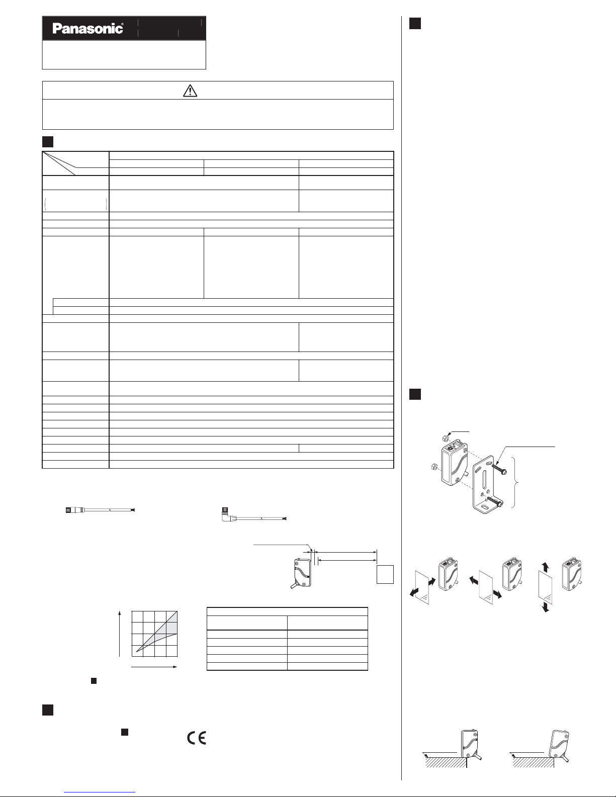
The adjustable range stands for the maximum sensing range which can
be set with the adjuster. The sensor can detect an object 0.1m, or more,
away. However, the detectable area of the Near (Sub) type of the
EQ-34W begins at 0.2m.
0.2m
0.1m
2m
Non-detectable range
Actual sensing
range of the sensor
Adjustable range
Sensing
object
3)
The Near (Sub) distance adjustable range, L2, changes with the setting of the Far (Main) distance, L1, as shown in the table below.
EQ-34W Near (Sub) distance adjustable range
EQ-34W
Far (Main) setting distance L
1
Near (Sub) distance
adjustable range L
2
2m 1 to 2m
0.2m 0.2m
1.5m 0.85 to 1.5m
1m 0.65 to 1m
0.5m 0.35 to 0.5m
0 0.5 1 1.5 2
2
1.5
1
0.5
Far (Main) setting distance L
1 (m)
Near (Sub) distance
adjustable range
L
2 (m)
MOUNTING
4
● The tightening torque should be 0.8N・m or
less.
M4 nut
M4 (length 25mm)
screw with washers
Sensor
mounting
bracket
MS-EQ3-2
(Optional)
● Care must be taken regarding the sensor
mounting direction with respect to the object's
direction of movement.
Do not make the sensor detect an object
in this direction because it may cause
unstable operation.
Sensing object
Not good
Sensing object
Good
Sensing object
Good
●●When detecting a specular object (aluminum or
copper foil, etc.) or an object having a glossy
surface or coating, please take care that there
are cases when the object may not be detected
due to a small change in angle, wrinkles on the
object surface, etc.
When a specular body is present below the
sensor, use the sensor by tiling it slightly upwards to avoid wrong operation.
Specular face
Not good
Tilt
Good
Specular face
●●Never use this product as a sensing device for personnel protection.
In case of using sensing devices for personnel protection, use products which meet laws and standards, such as OSHA, ANSI or IEC etc., for personnel protection applicable in each region or country.
WARNING
●
The models listed under ' SPECIFICATIONS'
come with CE Marking.
As for all other models, please contact our office.
1
INTENDED PRODUCTS FOR
CE MARKING
2
Adjustable Range Reflective Photoelectric Senso
r
EQ-30 Serie
s
INSTRUCTI
ON
MANUA
L
●●If a specular body is present in the background,
wrong operation may be caused due to a small
change in the angle of the background body. In
that case, install the sensor at an inclination
and confirm the operation with the actual sensing object.
Some object may produce the dead zone right
in front of the sensor.
●
Since the EQ-30 series uses a 2-segment photodiode as its receiving element, and sensing is
done based on the difference in the incident
beam angle of the reflected beam from the
sensing object, the output and the operation indicator operate according to the object distance.
Further, the stability indicator shows the margin
of the incident light intensity and not that of the
object distance.
Hence, the distance at which it lights up / OFF
depends on the object reflectivity and is not at
all related to the output operation. Do not use
the sensor when the stability indicator is OFF
(unstable light received condition), since the
sensing will be unstable.
STABILITY INDICATOR
6
Sensor
Setting distance
Sensing
object
Sensing
object
Sensing
object
Output
(operation indicator)
(In case of Detection-ON)
Stability indicator
(Black non-glossy paper)
Stability indicator
(White non-glossy paper)
Stable light
received condition
Stable dark
condition
Stable light
received condition
Stable dark
condition
Unstable light
received condition
Unstable light
received condition
ON (Lights up)
Lights up
Lights up
OFF (Turns off)
Turns off
Turns off
I/O CIRCUIT DIAGRAMS
5
●
Connector pin position of the connector type
Not connected
2
Output
4
+V
1
0V
3
● NPN output type / EQ-34
Symbols...D
Z
D
Tr
: Reverse supply polarity protection diode
: Surge absorption zener diode
: NPN output transistor
D
T
r
ZD
+
-
10 to 30V
DC
Internal circuit Users' circuit
Load
(Black
/
4) Output
(Blue / 3) 0V
(Brown / 1) +V
Color code / Connector pin No.
of the connector type
100mA max.
Main circuit
Symbols...D
Z
D
Tr
: Reverse supply polarity protection diode
: Surge absorption zener diode
: PNP output transistor
● PNP output type / EQ-34-PN
(Black / 4) Outpu
t
(Blue
/
3) 0V
(Brown /
1) +V
Color code / Connector pin No.
of the connector type
D
Tr
ZD
+
-
10 to 30V
DC
Internal circuit Users' circuit
100mA max.
Main circuit
L
oad
● Two outputs type / EQ-34W
Symbols...D: , Reverse supply polarity protection diode
Z
D1, ZD2: Surge absorption zener diode
T
r1, Tr2: NPN output transistor
(
Blue) 0V
(Brow
n) +V
D
T
r1
ZD1
+
-
10 to 30V
DC
Internal circuit Users' circuit
(Black) Far
(
Main) output
100mA max.
Tr2
ZD2
(White) Near (Sub) output
100mA max.
Color code
Main circuit
L
oad
Load
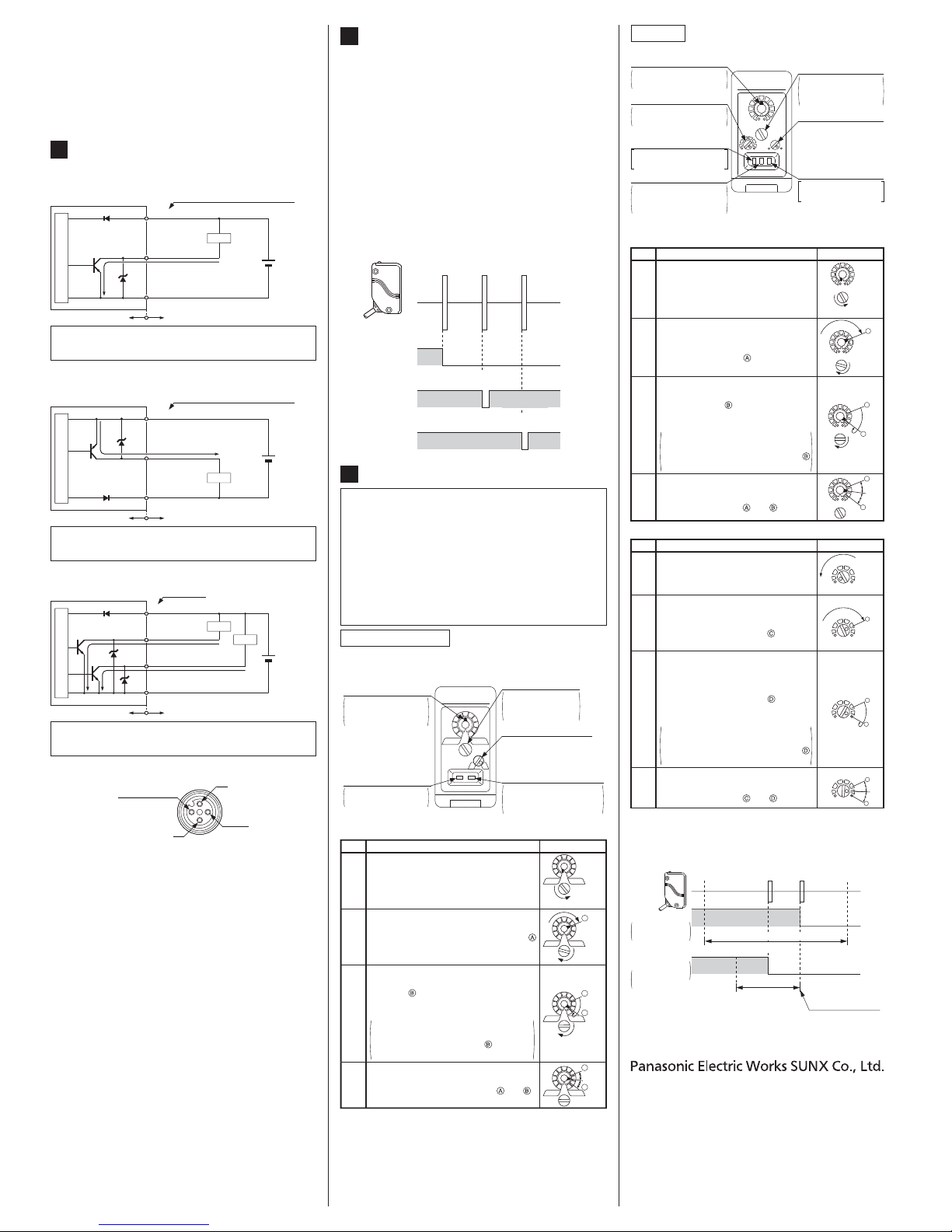
DISTANCE ADJUSTMENT
7
EQ-34, EQ-34-PN
● Adjusting procedure
Note: Use the accessory adjuster screwdriver to turn the distance
adjuster slowly. Turning with excessive force will cause damage the adjuster.
①
②
③
④
Turn the distance adjuster fully counterclockwise to the minimum sensing range
position of 0.2m approx.
Place an object at the required distance
from the sensor, turn the distance adjuster
gradually clockwise, and find out point
where the sensor changes to the light received condition.
Remove the object, turn the distance adjuster further counterclockwise, and find
out point where the sensor changes to
the light received condition again with only
the background.
When the sensor does not go to the light
received condition even if the adjuster is
fully turned clockwise, point is this extreme point in the range.
The optimum position to stably detect objects is the center point between and .
Step
Distance adjuster
Description
NEAR
FAR
Turn fully
A
NEAR
FAR
A
NEAR
FAR
B
A
NEAR
FAR
B
Optimu
m
position
● Top-view
NEAR
FAR
L
D
Operation mode switch
L: Detection-ON
D: Detection-OFF
(Turn the switch fully.)
Adjuster indicator
Shows how much
the distance adjuster is rotated.
Distance adjuster
(2-turn)
The sensing range
increases as it is
turned clockwise.
Stability indicator (Green)
Lights up under stable
light received condition
or stable dark condition.
Operation indicator
(Red)
Lights up when the
output is ON.
EQ-34W
● Top-view
STB
NEAR
FAR
DL
SUB
MAIN
MODE
SUB MAIN
Far (Main) output
operation indicator (Red)
Lights up when the Far
(Main) output is ON.
Operation mode switch
L: Detection-ON
D: Detection-OFF
(Turn the switch fully.)
Far (Main) adjuster indicator
Shows how much the distance adjuster is rotated.
Near (Sub) distance adjuster
The sensing range increases as it is turned clockwise.
Far (Main) distance
adjuster (2-turn)
The sensing range
increases as it is
turned clockwise.
Stability indicator (Green)
Lights up under stable
light received condition
or stable dark condition.
Near (Sub) output
operation indicator (Red)
Lights up when the Near
(Sub) output is ON.
●・Adjusting procedure
Far (Main) side
①
Turn the Far (Main) distance adjuster
fully counterclockwise to the minimum
sensing range position of 0.2m approx.
Step
Distance adjuster
Description
NEAR
FAR
MAIN
Turn fully
②
③
④
Place an object at the far place at the required distance from the sensor, turn the
Far (Main) distance adjuster gradually clockwise, and find out point where the sensor
changes to the light received condition.
Remove the object, turn the Far (Main)
distance adjuster further clockwise, and
find out point where the sensor
changes to the light received condition
again with only the background.
When the sensor does not go to the
light received condition even if the adjuster is fully turned clockwise, point
is this extreme point in the range.
The optimum position to stably detect
objects for the Far (Main) setting is the
center point between and .
A
B
NEAR
FAR
MAIN
Optimum
position
NEAR
FAR
MAIN
A
A
B
NEAR
FAR
MAIN
・ Near (Sub) side
①
②
③
④
Turn the Near (Sub) distance adjuster
fully counterclockwise to the minimum
sensing range point.
Step
Distance adjuster
Description
SUB
C
Turn fully
SUB
SUB
C
D
SUB
Optimum
position
C
D
Place an object at the near position, at the
required distance from the sensor, turn the
Near (Sub) distance adjuster gradually
clockwise, and find out point where the
sensor changes to the light received condi-
The optimum position to stably detect
objects for the Near (Sub) setting is the
center point between and .
Remove the object from the near position, and place the object for Far (Main)
sensing at the sensing position. Turn the
Near (Sub) distance adjuster further
clockwise, and find out point where the
sensor changes to the light received condition again with only the background.
When the sensor does not go to the
light received condition even if the adjuster is fully turned clockwise, point
is this extreme point in the range.
Notes: 1)
2)
Use the accessory adjuster screwdriver to turn the distance adjuster
slowly. Turning with excessive force will cause damage the adjuster.
The Far (Main) distance adjustment should be done before the Near
(Sub) distance adjustment. Take care that the Near (Sub) setting
distance changes with change in the Far (Main) setting distance.
Near (Sub)
setting distance
Far (Main)
setting distance
Near object Far object
ON
OFF
ON
OFF
Near (Sub) distanc
e
adjustable ran
ge
EQ-34W
Far (Main) distance adjustable range
(0.2 to 2m)
Near (Sub) distance ad
j
uster set
a
t the maximum
.
Far (Main) output
In case of
Detection-ON
Near (Sub) output
In case of
Detection-OFF
The following distance adjusting procedure for
EQ-34, EQ-34-PN and the Far (Main) side / Near
(Sub) side of EQ-34W is for use when a sensing
object moves horizontally to the sensor. When a
sensing object is approaching / moving away
from the sensor, follow only steps ① and ② respectively.
Since the sensing point may change depending
on the sensing object, be sure to check the operation with the actual sensing object.
© Panasonic Electric Works SUNX Co., Ltd. 2010
PRINTED IN JAPAN
htt
p
://panasonic-electric-works.net/sun
x
Overseas Sales Division (Head Office
)
2431-1 Ushiyama-cho, Kasugai-shi, Aichi, 486-0901, Japan
Phone: +81-568-33-7861 FAX: +81-568-33-8591
Europe Headquarter: Panasonic Electric Works Europe AG
Rudolf-Diesel-Ring 2, D-83607 Holzkirchen, Germany
Phone: +49-8024-648-0
US Headquarter: Panasonic Electric Works Corporation of America
629 Central Avenue New Providence, New Jersey 07974 USA
Phone: +1-908-464-3550
 Loading...