

PANASONIC ECPUA330N 16 Datasheet
Stacked Metallized Plastic
Film Chip Capacitor
Type : ECPU(A)
Stacked dielectric and inner electrode with simple
mold - less construction
Features
●
Low ESR
●
Max. capacitance values 1.0 F
●
Smallest package size in fi lm capacitors 3225/1.0 F
●
For refl ow soldering
●
RoHS directive compliant
Recommended applications
●
Noise suppressor
●
Audio circuit
Explanation of part number
Plastic Film Capacitors
1 2 3 4 5 6 7 8 9 11 12
E C P U 1 C 5A
Product code Dielectric &
construction
1C 16 V.DC
10
M
Cap. Tol.
Speci cations
Category temp. range
(Including temperature-rise on unit surface)
Rated voltage 16 V.DC
Capacitance range 0.10 µF to 1.0 µF (E6)
Capacitance tolerance ±20 %(M)
Dissipation factor (tan d) tan d < 1.5 % ( 20 °C, 1 kHz )
Withstand voltage Between terminals : Rated volt (V.DC)×150 %, 60 s
Insulation resistance (IR)
Soldering conditions
In case of applying voltage in alternating current (50 Hz or 60 Hz sine wave) to a capacitor with DC rated voltage,
✽
please refer to the page of “Permissible voltage (R.M.S) in alternating current corresponding to DC rated voltage”.
C < 0.33 F : IR > 1000 MΩ (20 °C, 10 V.DC, 60 s)
C > 0.33 F : IR > 300 MΩ µF (20 °C, 10 V.DC, 60 s)
Refl ow soldering : 240 °C max. and 30 sec max. at more than 220 °C
– 40 °C to +85 °C
(Temp. at capacitor surface)
SuffixRated voltage Capacitance Suffix
Code
5
Tape width
8 mm
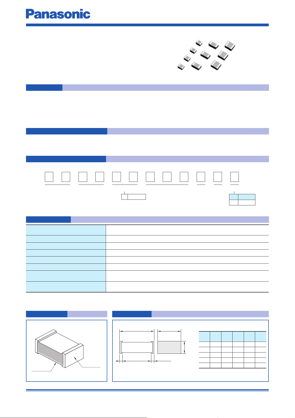
Construction Dimensions
L±0.2
Element
(Stacked)
Design and specifications are each subject to change without notice. Ask factory for the current technical specifications before purchase and/or use.
Should a safety concern arise regarding this product, please be sure to contact us immediately.
Outer
electrode
e±0.30
(±0.25)
g
e±0.30
✽
✽ To be applied only for size code J1
(±0.25)
✽
W±0.20
Size
code
J1 2.0 1.25 1.0
H1 3.2 1.6 0.8
H±0.2
H2 3.2 1.6 1.0
H3 3.2 1.6 1.4
G2 3.2 2.5 1.4
LWHe g
Unit : mm
0.45> 0.6
0.65> 1.0
0.65> 1.0
0.65> 1.0
0.65> 1.0
Sep. 201702
Taping s p eci cation for automatic mounting
Refer to the page of taping specifi cations
Rating · Dimensions · Quantity
Plastic Film Capacitors
Capacitance
(µF)
Part No.
Dimensions (mm)
LWH
0.10 ECPU1C104MA5 2.0 1.25 1.0 J1
0.15 ECPU1C154MA5 3.2 1.6 0.8 H1
0.22 ECPU1C224MA5 3.2 1.6 0.8 H1
0.33 ECPU1C334MA5 3.2 1.6 1.0 H2
0.47 ECPU1C474MA5 3.2 1.6 1.4 H3
1.0 ECPU1C105MA5 3.2 2.5 1.4 G2
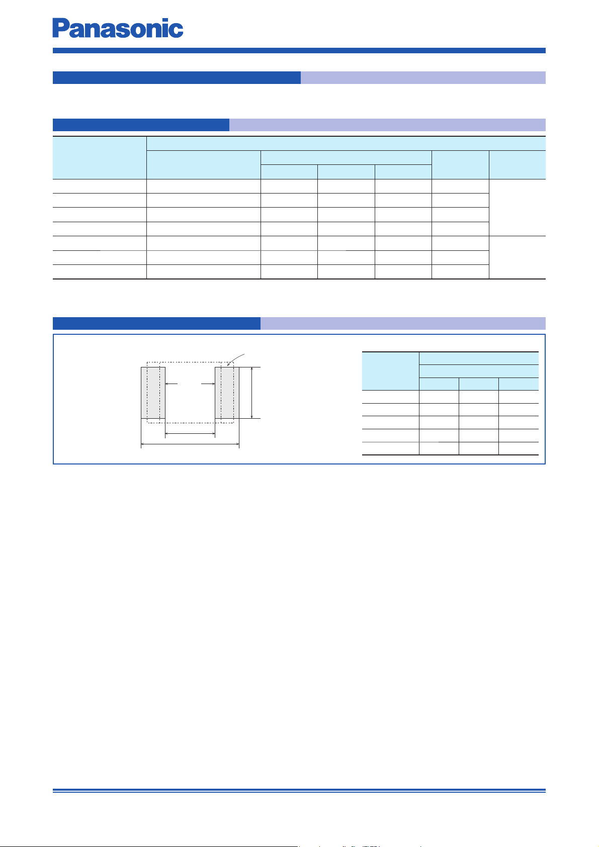
Recommended for land dimensions
Electrode
Size code
Rated voltage 16 V.DC
Land
A
B
C
J1 0.8 2.4 1.1
H1 1.8 3.6 1.4
H2 1.8 3.6 1.4
H3 1.8 3.6 1.4
G2 1.8 3.6 2.3
Size code Q'ty
3000
20000.68 ECPU1C684MA5 3.2 1.6 1.4 H3
Unit : mm
Land dimensions
Refl ow soldering
ABC
lt is not warrantable that you can mount the capacitor without trouble under all the mounting condition when “Recommender for Land dimensions” is adopted.
✽
Design and specifications are each subject to change without notice. Ask factory for the current technical specifications before purchase and/or use.
Should a safety concern arise regarding this product, please be sure to contact us immediately.
Sep. 201702
 Loading...