

Page 1

EchoMap 3.0
User’s Guide
1919 14th St. Suite 601
Boulder, Co. 80302
Customer Support
1-888-739-7161
Support@EchoFlight.com
www.EchoFlight.com
Page 2

EchoMap v3.0
This Manual is for users of EchoMap, on
an Echo Flight Flight Cheetah Multi-
Function-Display or a Windows® laptop.
An electronic version of this manual will be
installed to
/Echomap/Docs/EchoMapGuide.pdf
2
1/22/2002
Version 3.0
Page 3

EchoMap v3.0
3
ding 91.21
Please read the following information
• Echo Flight provides weather and messaging only in the Continental U.S. and
surrounding offshore areas
• Echo Flight continues to develop new technologies to provide pilots with new and
exciting ways to gather information in the cockpit. For a full understanding of
how the system should be used, please refer to the Echo Flight, Inc. Services and
Systems Agreement.
• This product is meant to augment, not replace pilot voice communication with
Flight Service Stations (FSSs), other Air Traffic Control (ATC) facilities or Airlines
Operations Control Centers (AOCCs). It does not replace pilot and
controller/FSS/aircraft dispatcher voice communication for critical weather or
operational information interpretation. Please verify all information including
navigational and weather information from independent sources before
considering it valid.
• Before using Echo Flight products during flight, you should become completely
familiar with the operation of the system and equipment as well as modes of
operation and indications of various system failures.
• Although governmental Selective Availability for GPS has been removed, altitude
information should not be used for vertical navigation.
• This system is for portable use. Please observe all FAA regulations inclu
regarding the use of portable equipment in the cockpit. This product is not IFR
certified. It is for advisory use only and is designed to supplement other sources
of flight data while enroute. For additional information please refer to the
Airman’s Information Manual concerning weather avoidance.
• Take care positioning and securing equipment so it is free and clear of all controls,
instruments, doors and windows. As with any transceiver, contact with an
antenna while transmitting may cause electrical shock.
• Always make sure NOS approach plates are current. Approach plate information
should be printed before flight in case of electrical failure. Always make sure you
have the most current updated information.
• All aircraft are certified with a maximum allowable weight to be placed on the
control yoke. Assume that the computer exceeds this amount and should not be
mounted on the yoke unless your aircraft manufacturer approves. Please
remember that any object on the control yoke may cause a potentially dangerous
flywheel effect if poorly centered. If you have any mounting questions please
contact your A&P mechanic.
• Information in this document is subject to change without notice.
Page 4

EchoMap v3.0
Table of Contents
1. Introduction...............................................................................7
1.1 System Requirements ..........................................................7
1.2 Data-Link and GPS...............................................................7
2. Flight Display Indicators ..........................................................8
2.1 Heading Indicator..................................................................9
2.2 Obstacle Alert Indicator ........................................................9
2.3 Direct to Indicator..................................................................9
2.4 Position Indicators ..............................................................10
2.5 Satellite Status Indicators...................................................10
2.5.1 Satellite Indicator Colors.................................................11
2.5.2 Satellite Indicator Examples ...........................................12
2.6 Moving Map Panel..............................................................13
3. GPS Moving Map.....................................................................14
3.1 Navigation Menu.................................................................14
3.2 Demo Mode........................................................................15
3.3 Map Range Controls...........................................................15
3.4 Navaid Overlays..................................................................16
3.5 Terrain Contour...................................................................16
3.5.1 Display the Terrain Contour Overlay ................................................16
3.5.2 Display Black Background............................................................16
3.6 Terrain & Tower Alerts........................................................16
3.6.1 Terrain Alert Indicator ..............................................................17
3.6.2 Tower Alert Indicator ...............................................................17
3.6.3 Terrain Alert Display.................................................................17
3.7 Display The Terrain Alert Overlay.......................................18
3.8 Display The Terrain Contour and Alert Overlay..................18
3.9 Moving Map - Display Settings ...........................................19
3.9.1 Change Your Map Compass Display..............................20
3.9.2 Display Course Lines......................................................20
3.9.3 Other Map Display Settings............................................20
3.10 Map Menu - Layers.............................................................21
3.10.1 Add or Delete a Map Layer.............................................21
3.10.2 Keyboard Shortcuts for Layers .......................................22
3.11 Map Menu - Filter Settings..................................................22
3.11.1 Change Filter Settings ....................................................23
4. DATABASE INFORMATION....................................................24
4.1 Airport Information..............................................................24
4
Page 5

EchoMap v3.0
5
4.1.1 Airport Facility Page........................................................24
4.1.2 Airport Frequency Page..................................................25
4.1.3 Airport Map Page............................................................25
4.1.4 Airport Metar Weather Page...........................................26
4.1.5 Airport Plates Page.........................................................26
4.2 VOR Info Page ...................................................................28
4.3 NDB Info Page....................................................................28
5. Routes & Approach Overlay..................................................29
5.1 Create a New Route...........................................................29
5.2 Select an Existing Route ....................................................30
5.3 Add User Waypoint ............................................................30
5.4 Insert or Delete a Waypoint in an Existing Route...............30
5.5 Direct To Menu...................................................................31
5.5.1 Select Next Waypoint.....................................................31
5.5.2 Reverse Route................................................................31
5.5.3 Approach Overlay ...........................................................32
5.5.4 Selecting an Approach ...................................................32
5.5.5 Viewing the Approach (requires Plates subscription).....33
6. System Menu...........................................................................34
6.1.1 Shut Down the Computer...............................................34
6.1.2 Exit to Windows ( laptop computers only ).....................34
6.1.3 Update from CD .............................................................34
6.1.4 System Settings Menu....................................................35
6.1.5 System Diagnostics Menu..............................................35
6.1.6 Minimize ( laptop computers only ).................................35
7. DATA-LINK Weather...............................................................37
7.1 Data Link Weather vs. Onboard Radar..............................39
7.2 NexRAD Weather Radar....................................................39
7.2.1 Requesting a NexRad Image .........................................41
7.2.2 Changing NexRad Request Range................................41
7.2.3 Changing NexRad Request Direction.............................41
7.2.4 Automatic NexRad Requests .........................................42
7.2.5 Remote NexRad Request ..............................................42
7.2.6 NexRad Radar Animation...............................................42
7.3 Interpreting NexRAD Radar Pictures .................................43
7.3.1 Storm Cells.....................................................................44
7.3.2 NexRAD Picture Boundaries..........................................44
7.4 Metar Reports.....................................................................45
7.4.1 Graphical Metar Reports ................................................45
7.4.2 Interpreting Graphical Ceiling / Visibility Reports...........46
7.4.3 How to Read Precipitation Levels...................................46
7.4.4 Interpreting Metar Age....................................................46
7.4.5 Metar Ceiling/Visibility Example......................................47
Page 6

EchoMap v3.0
7.4.6 How to read Graphical Wind Speed and Direction.........48
7.4.7 How to read Graphical Temperature Dew-point Spreads49
7.4.8 How to View Weather Overlays......................................49
7.5 Text Metar Reports.............................................................50
8. In Flight Email..........................................................................51
8.1 How to Send Email.............................................................51
8.2 Receiving Email..................................................................52
8.2.1 Email Login.....................................................................53
8.3 Position Reporting ..............................................................53
9. The ORBCOMM Data Link Network.......................................54
9.1 Advantages of LEO Technology.........................................54
9.2 Network Operation..............................................................55
9.2.1 Space Segment..............................................................55
9.2.2 Ground Segment ............................................................55
9.2.3 Aircraft Segment.............................................................57
10. TECHNICAL Support...............................................................59
10.1 Log Files.............................................................................59
10.2 Disk Space..........................................................................59
10.3 EchoFlight Online ...............................................................59
APPENDIX A: Keyboard Shortcuts.................................................60
Appendix B: Glossary......................................................................62
6
Page 7

EchoMap v3.0
7
11.. IINNTTRROODDUUCCTTIIOONN
This Manual is for users of the EchoMap software running on a either
an Echo Flight Flight Cheetah Multi-Function-Display or a Windows
laptop/tablet computer.
Reading this manual will introduce you to the powerful features and
functions of EchoMap. You should install software on your home
computer to practice in demo mode. See section 4.2.1.
1.1 System Requirements
If you are not using the software on a Flight Cheetah flight
computer, it is recommended that you use a Pentium class
Windows® laptop or tablet computer. WinCE is not supported.
Requirements Minimum Recommended
Operating System Windows 95, 98, ME, XP Windows NT4, 2000
Processor Pentium 75 MHz Pentium III 500 MHz or more
RAM (megabytes) 16-32 64-128 or more
Hard Drive 500 megabytes 1 gigabyte or more
Ports 1 serial or USB port 2 serial or USB port
At least one RS-232 serial port is required to communicate with
the Satellite Transceiver and/or GPS Receiver (USB to Serial
adapters are available). A faster processor or more RAM will
improve system performance. A CD-ROM drive is required to
install software and updates, but is not required for use in-flight.
Warning - When using a mobile computer in the cockpit, special care
should be taken to place the screen out of direct sunlight, in an easily
viewed area that does not interfere or block any controls or instruments.
1.2 Data-Link and GPS
EchoMap is designed to work with the Quake and Panasonic
brands of ORBCOMM satellite communicator (SC). These SCs
provide integrated GPS functionality. EchoMap also supports the
use of a separate NMEA GPS receiver on a serial/usb port to run
without an SC or to replace the SC’s integrated GPS. If you use
both an SC and a NMEA GPS, you will need at least two serial or
usb ports.
Page 8
EchoMap v3.0
22.. FFLLIIGGHHTT DDIISSPPLLAAYY IINNDDIICCAATTOORRSS
EchoMap has been optimized for maximum flexibility, capability and
ease of use in flight. Please take a few moments to review its
functions to get the most of its capabilities.
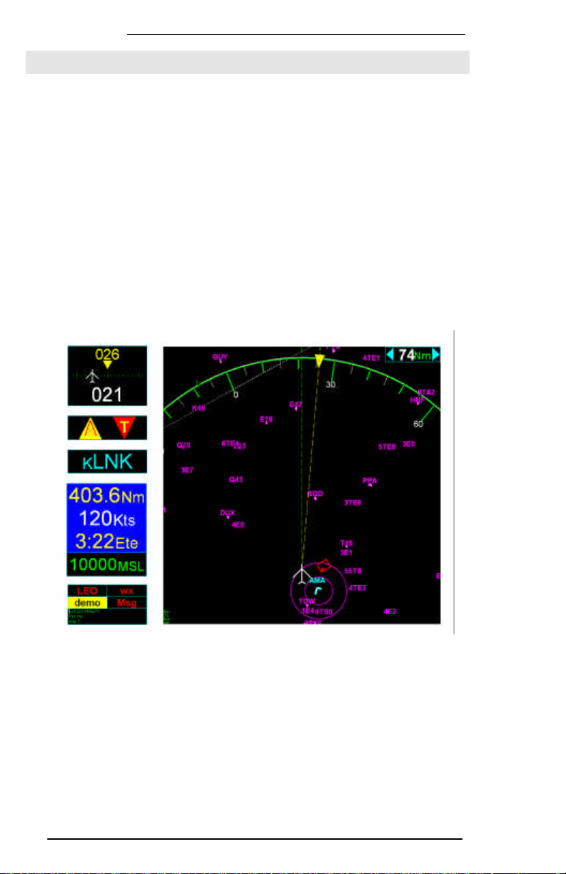
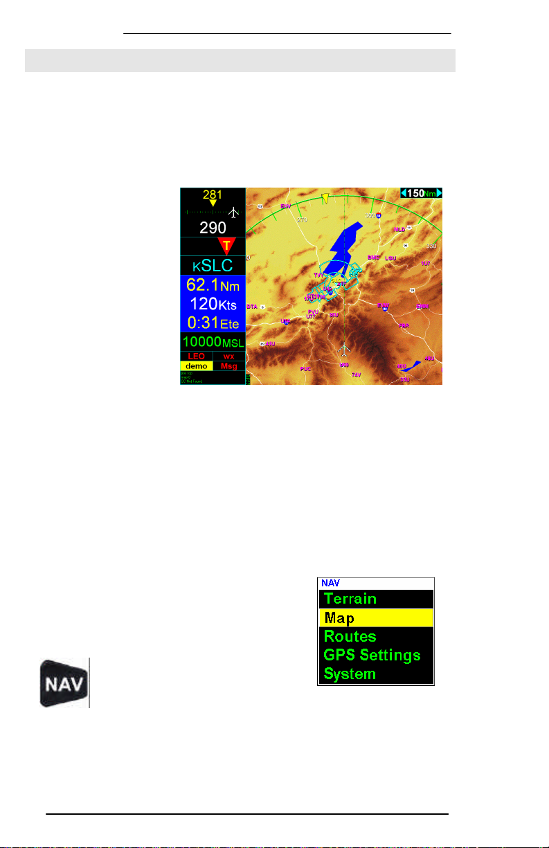
The flight display screen consists of six separate sections:
1. Heading information, upper left panel.
2. Obstacle Alert, second down on left.
3. Direct to location, third down on left.
4. Position information, lower center left panel.
5. GPS and ORBCOMM Satellite Status, lower left panel.
6. Moving Map display, right hand panel.
EchoMap will scale to fit any display resolution. Layout will differ
depending on whether it is displayed in portrait or landscape
mode. Landscape mode is shown above. In portrait mode the
indicators display on top of the map.
8
Page 9
EchoMap v3.0
9
map. When an airport is displayed in cyan it indicates a controlled
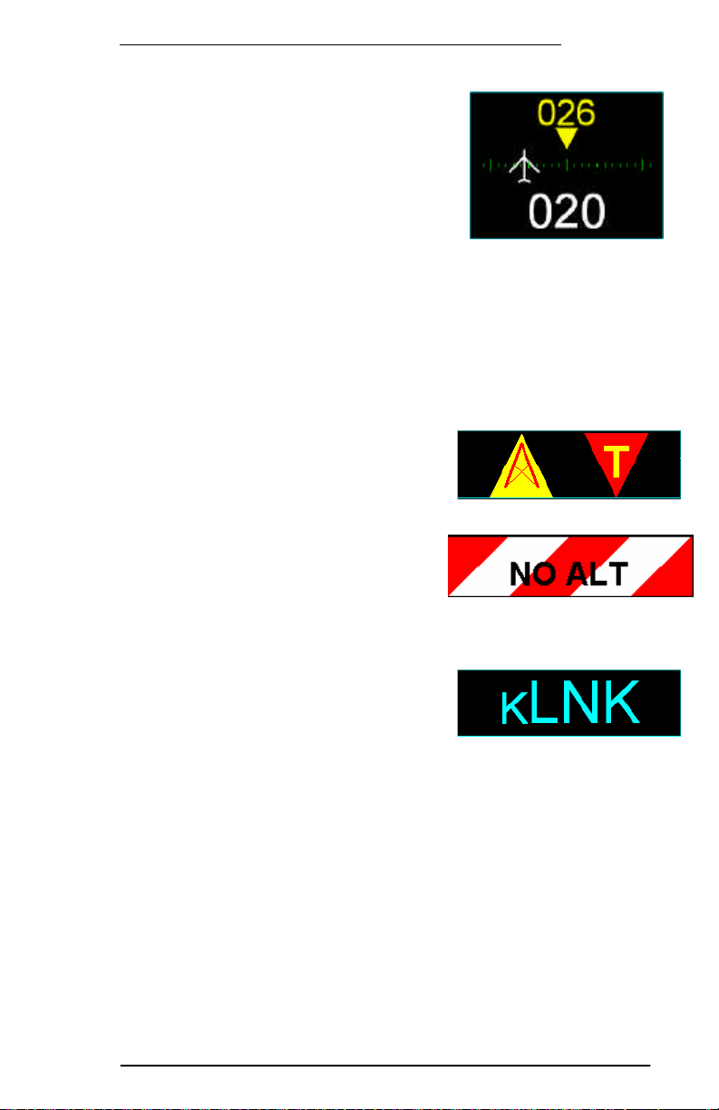
2.1 Heading Indicator
The first section of the flight display
is the heading indicator in the upper
left corner of the screen. The top
yellow number is the magnetic
heading to your waypoint. The lower
white number is your actual current
track. The visual aircraft indicator shows the number of degrees
off course, in this case 6 degrees to the left of the correct heading
represented by the yellow triangle below the magnetic heading.
The tick marks show how many degrees your aircraft is off course
in one-degree increments up to a maximum deflection of 11
degrees. Navigation is as simple as flying towards the triangle.
2.2 Obstacle Alert Indicator
The obstacle alert indicator panel
will automatically display either a
tower or terrain alert symbol when
the aircraft comes within 8 minutes
and 500 feet of an obstacle. If no
GPS altitude is available, this alert
indicator will show a red and white striped bar.
2.3 Direct to Indicator
The third panel displays the
currently selected target waypoint,
which may be an airport, VOR, NDB, intersection or custom
waypoint. The color of the text matches the color of item on the
airport in the destination while magenta would indicate an
uncontrolled airport.
Page 10
EchoMap v3.0
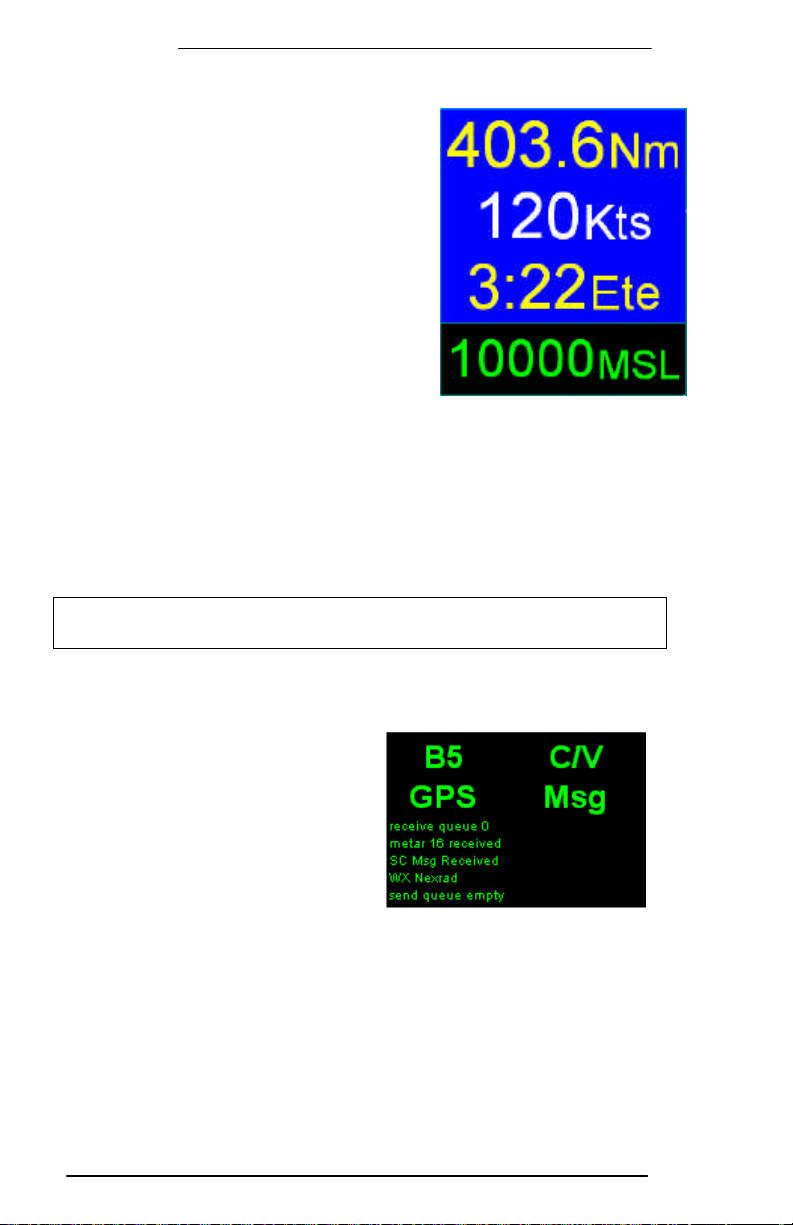
2.4 Position Indicators
Directly below the direct to indicator is
the navigation box. This box displays
current navigational information during
flight. The first two lines are Distance
to the Waypoint and Ground Speed.
The third line displays the Estimated
Time Enroute (ETE) to the target
waypoint. ETE is computed on your
actual track and closure rate, (not just
distance divided by ground speed), to
give you an extremely accurate time.
For this reason, the ETE indicator will disappear when your track is
90 degrees or more off from the target heading.
The final line indicates your altitude in feet above mean sea level.
This altitude will appear in yellow when your aircraft is 500-1000
feet above the terrain and red when within 500 feet or less. When
GPS reception is less than 4 satellites no altitude is displayed and
you will receive a No Alt warning in the Obstacle clearance panel.
Note: Although government Selective Availability has been removed, the
system is not to be used for primary vertical navigation or IFR navigation.
2.5 Satellite Status Indicators
Directly below the navigation box
are the satellite status indicators.
There are four indicators, upperleft is the status of the
ORBCOMM satellite connection,
lower-left is the GPS lock status,
upper right is the WX status
which lets you know what
weather product is being displayed, and lower right is the Msg
status. The indicators will also display an arrow up or down to
show that the system is transmitting or receiving data from the
satellite.
Below these indicators is a small text box that outputs status
information that is written to status log. The text is small because
it is not necessary to read this information during flight.
10
Page 11
EchoMap v3.0
11
2.5.1 Satellite Indicator Colors
The ORBCOMM status indicator shows whether you have established a
link with the satellites and whether you are transmitting or receiving.
Color ORBCOMM Satellite Indications (upper left)
No signal is being received on the serial port or the satellite
Red
Yellow
Green
White
arrow
The GPS indicator shows whether you have established reception of the
GPS constellation.
Color GPS Lock Indications (lower left)
Red
Yellow
Green
transceiver has failed its initial check and verification.
Remedy: Confirm that the satellite transceiver is receiving
power and is connected securely to the computer’s serial port
using the provided serial cable.
The satellite transceiver is operating correctly and is ready to
receive or transmit data, but no ORBCOMM satellite is in view.
You are currently in view of an ORBCOMM satellite. Dotted
Green and Red bars indicate Signal Strength and Noise.
Arrow pointed up means satellite transceiver is transmitting
data to satellite.
Arrow pointed down means satellite transceiver is receiving
data from satellite.
No signal is being received from the satellite transceiver or it
has failed its initial check and verification.
Remedy: Confirm that the satellite transceiver has power and
is securely connected to the computer’s serial port.
GPS signal is being received, but the GPS receiver has not yet
locked on to at least three satellites.
Remedy: If the GPS indicator remains yellow, double-check
the GPS antenna connection and placement.
Note: The first time the system is used, the GPS may take
some time to lock on.
Locked on to at least three satellites with good geometry,
providing real-time position for the moving map. If you are
using a WAAS GPS, a WAAS lock is indicated by “WAAS” black
text on green.
The Weather indicator shows the status of weather requests as well as
the age of weather.
Color WX Status Indications (upper right)
Red
Yellow
Current weather is over an hour old, or Demo weather
displayed.
A request for weather has been made but not yet received.
Green Weather under an hour old displayed. Shows the age.
The message indicator shows the status of message requests.
Color Message Status Indications (lower right)
Red
Yellow
No queue count available from satellite transceiver.
Messages are queued to send.
Page 12

EchoMap v3.0
Green
Send queue empty and waiting.
2.5.2 Satellite Indicator Examples
You have no connection with the Satellite
transceiver. All indicators are red.
You have a connection with the satellite
transceiver, but no lock with either GPS
or ORBCOMM satellites. You have made
one WX request, which is waiting for a
connection to send. If this persists,
check your antenna or verify antennas
have a clear sky view.
Poor lock on with ORBCOMM Sat A3, all
noise (red bar). WX not requested
(red), no GPS lock (yellow), empty Msg
queue.
Locked on to Sat B8 (green) with 70%
Signal Strength and no noise. Sending
data (white arrow up), GPS locked
(green), NexRAD request pending
(yellow), and one message in queue
waiting to be sent (yellow Msg1).
12
Locked onto ORBCOMM Sat D8 (green),
with 100% Signal Strength, receiving
data (white arrow down), GPS locked
(green), weather request for NexRAD is
pending (yellow), no messages are
waiting to be sent (green Msg).
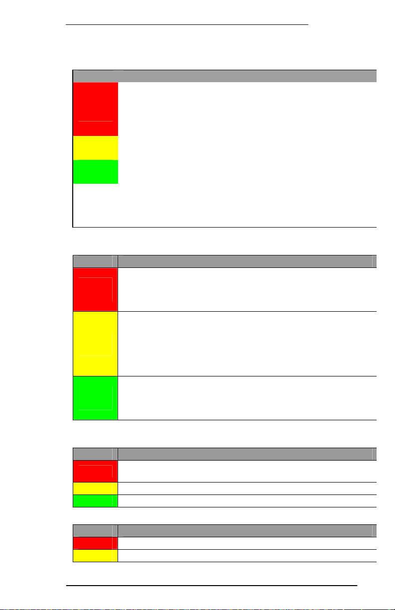
All green. Lock to Sat B5 with a little
noise (dotted red bar). Metar (C/V)
information received less than an hour
ago, and no messages are waiting to be
sent (green Msg).
All green. Locked onto ORBCOMM Sat
D8, GPS locked, NexRAD image displayed
5 minutes old, and no messages are
waiting to be sent.
Page 13
EchoMap v3.0
13
is the moving
data. To maximize situational awareness of presented data, colors
right corner of
2.6 Moving Map Panel
The sixth and largest section of the EchoMap display
map that shows your aircraft’s current position in relation to
airports, airspaces, Navaids, weather and a wide range of other
are chosen for optimum legibility and menus are logically grouped
for ease of use.
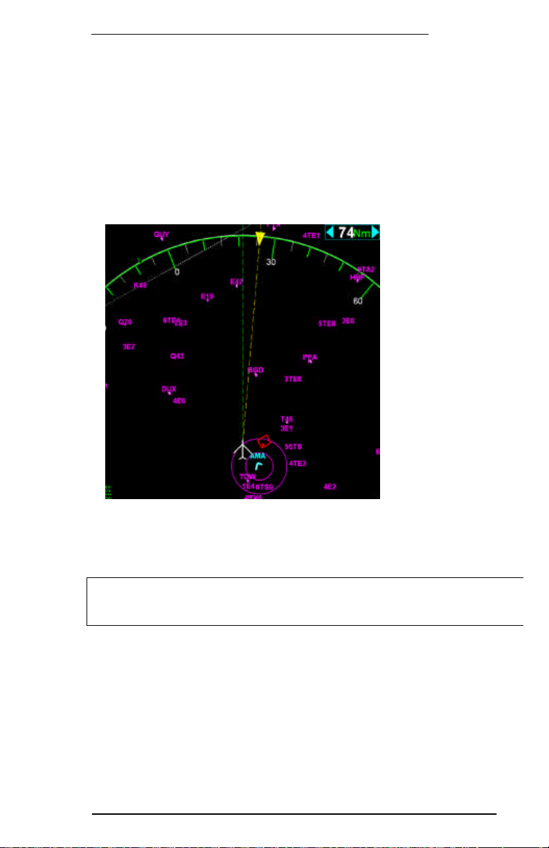
The map range is
displayed in the
upperthe moving map. It
indicates the
distance to the green compass ring or to top edge of the map if the
compass ring is off. Use the Left arrow key to decrease the range
(zoom in, down to 0.25Nm) and the Right arrow to increase the
range (zoom out, up to 2500Nm).
Press both left & right arrows simultaneously to enable auto-zoom
mode, which will automatically set the viewing range to show your target
waypoint. A yellow label indicates if auto-zoom is enabled.
Page 14
EchoMap v3.0
33.. GGPPSS MMOOVVIINNGG MMAAPP
Echomap has an extremely flexible GPS moving map. It has been
optimized for maximum capability in flight with minimum heads down
time. Please take a few moments to review its functions to get the
most of its capabilities.
Most features in
EchoMap are accessed
through five top level
menus that correspond
to the NAV, INFO,
MSG, WX and D->
keys on a Flight
Cheetah MFD, or the
F1-F5 keys on a
regular keyboard. If
you have installed
EchoMap on a touch
screen computer, a
menu bar is displayed to allow touch access to menus.
Use the up and down arrow keys to select items in the menus. The
selected item is highlighted with a yellow bar. Press the Enter key to
activate the selected item. You can close the menu by pressing the
same key you used to open it. Users with a touch screen close the
menu by clicking on white caption bar. You can go up from the top
of the menu to return to the parent menu.
3.1 Navigation Menu
The Navigation menu contains all of the
settings to customize the map display as
well as create flight routes and access the
system.
To access the Navigation menu
press the Nav button (F1).
From this menu you can select from the Terrain, Map,
Routes, Mode and System sub menus.
Terrain - The terrain menu lets you control how terrain is displayed on
the moving map.
14
Page 15
EchoMap v3.0
15
increases range. The range is displayed
Map - The map menu lets you customize the display options for the
moving map, including which layers of navaid data are displayed on the
map as well as filtering options.
Routes - The routes menu lets you create user defined routes and
waypoints.
GPS Settings - The mode menu lets you select whether the display
is in demo mode, GPS mode or playback. The default normally selects
GPS mode.
System - The System menu provides access to system
configuration and diagnostics, the operating system, and the
system shutdown/exit options.
3.2 Demo Mode
To most easily learn how to use Echomap before
flight it is suggested you operate the display in demo
mode. To operate in demo mode, First press the Nav
key ,Then scroll down to GPS Settings and press Enter. Next
scroll down to Demo and press Enter.
3.3 Map Range Controls
The Range keys? change your viewing range,
the left arrow decreases range and right
arrow
in nautical miles in the upper right hand corner box of the moving
map indicating the distance of your aircraft to the edge of the
green compass ring.
The viewing range will zoom down to .25 Nm and up to 2,500
Nm. Zooming closer than .25 Nm or Zooming farther than 2,500
Nm will cause the software to Enter into an auto-zoom function.
In the auto-zoom mode, the software will automatically make
the viewing range equal to the distance to your target waypoint.
Page 16
EchoMap v3.0
3.4 Navaid Overlays
The Up arrow and Down arrow allows you to scroll
through different customized layers of navigational
data such as airspace, highways and airways. To read
more on how to customize your own layers please
refer to 3.10
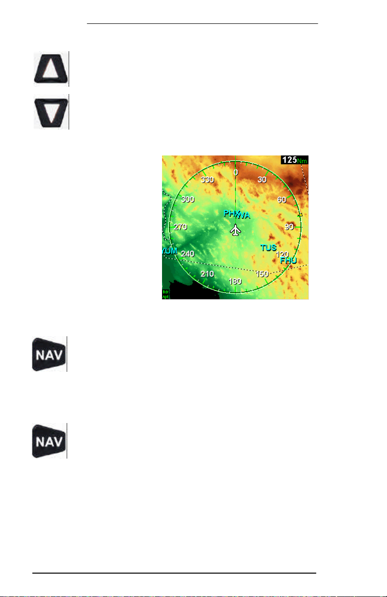
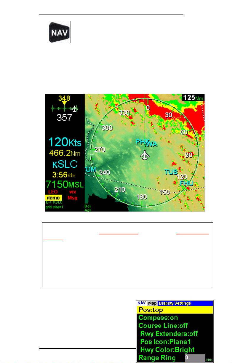
3.5 Terrain Contour
The terrain contour
background map displays
terrain in solid shades of
color. The color mapping is
based on the elevation
coloring of standard
sectional charts, but slightly
adjusted for improved onscreen visibility. The image
to the right shows the
aircraft position in Arizona.
Mexico is to the south.
3.5.1 Display the Terrain Contour Overlay
Press the Nav button, select Terrain. In the Terrain
menu select Map: ON and Mode: Map. Next press
Enter to remove the menu. You can toggle this function
on and off your moving map display by pressing Nav Enter
Enter.
3.5.2 Display Black Background
Press the Nav button, select Terrain. In the Terrain
menu select Map: OFF. Next press Enter to remove
the menu. You can toggle this function on and off your
moving map display by pressing Nav Enter Enter.
3.6 Terrain & Tower Alerts
EchoMap automatically displays alerts if your current altitude is
within 500ft of terrain or a tower in an 8 minute radius of your
current position. You are alerted to the terrain or towers that
would display red on the moving map. The alert indicators are
16
Page 17

EchoMap v3.0
17
positioned below the heading indicator. If there is no GPS altitude
bar that
EchoMap provides advisory worldwide terrain elevation data. The
the nearest 100ft, we help to insure that the error is on the side of
available, this area will display as a red and white slashed
says NO ALT or NO GPS. Terrain and tower alert conditions are
always calculated, even when terrain and towers are not being
displayed on the map.
3.6.1 Terrain Alert Indicator
Echomap will display a terrain alert icon if there
is terrain within 8 minutes ( based on your
current GPS ground speed ) and 500 ft of your
current altitude. Although the terrain alert
indicator is always enabled, you have the
option of deciding whether or not you want to view the color
coded areas of conflicting terrain on the moving map as shown on
the next page.
terrain database is derived from the USGS GTOPO30 global digital
elevation model (DEM). Elevations are regularly spaced at 30-arc
seconds (about 1 Km). Elevations are stored in 100ft increments
to save disk space. The terrain data may contain some degree of
error (especially outside of the United States). By rounding up to
caution. It is possible that some terrain features will not be
depicted in the data. Terrain data should never be used for
primary surface navigation
3.6.2 Tower Alert Indicator
Echomap will display a tower alert icon if there
is a tower within 8 minutes ( based on the
current GPS ground speed ) and 500 ft of your
current altitude. The tower alert function is
always enabled, and if there is a conflict the
obstacles are automatically displayed on the
moving map with the same color coding shown for terrain.
3.6.3 Terrain Alert Display
Page 18
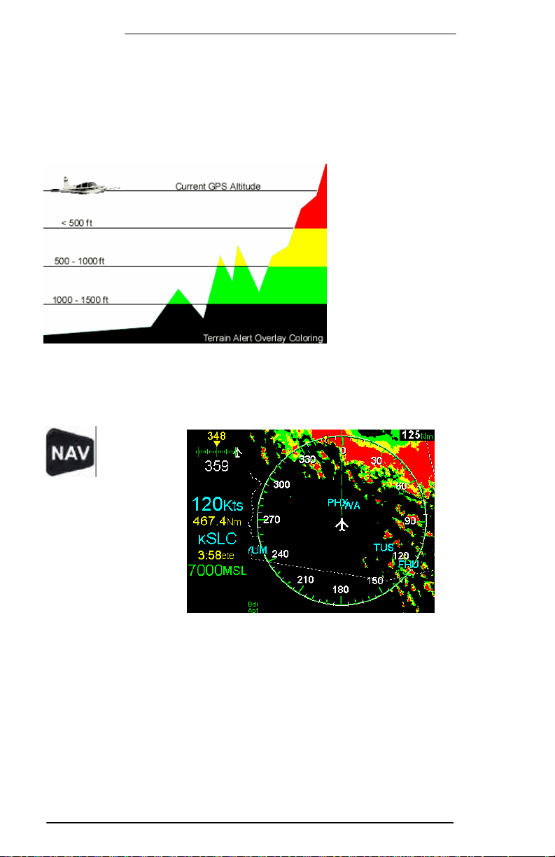
EchoMap v3.0
The terrain alert overlay shows only terrain that is within 1500
feet of your current GPS altitude. The terrain alert overlay is
color- coded so that areas within 500 feet of your altitude
display red, 500-1000 feet are in yellow and 1000 feet-1500
feet green. Anything in excess of 1500 feet clearance is not
displayed.
3.7 Display The Terrain Alert Overlay
Press the
Nav
button,
select Terrain. In
the Terrain menu
select Map: ON and
Mode: Alert. Next
press Enter to
remove the menu.
You can toggle this
function on and off
your moving map
display by pressing Nav Enter Enter.
3.8 Display The Terrain Contour and Alert Overlay
18
Page 19
EchoMap v3.0
19
You can toggle this function
Press the Nav button, select Terrain. In the Terrain
menu select Map: ON and Mode: Both. Next press
Enter to remove the menu.
on and off your moving map display by pressing Nav
Enter Enter.
The image below shows both the terrain contour map and alert
overlay at the same time. If NexRAD radar and terrain overlay are
both set on, the map will alternate between the dotted radar
images and the solid colors of the terrain alert.
Note - GPS altitude is used to compute tower and terrain alerts. The system
including GPS hardware is not IFR certified and is strictly for supplemental
use only. Even with increased accuracy since the termination of selective
availability, GPS altitude still varies above and below the actual altitude by
several hundred feet. This system is meant to supplement, but not replace,
primary sources of information such as current charts and altimeter settings.
All terrain and obstacle data provided by the US government. Although this
data is believed to be correct, there is the possibility that certain terrain or
obstacle data may be incomplete or inaccurate. If you find any inconsistencies
between this US government data and your current charts or observations
please notify Echo Flight support at 1-800-739-7161.
3.9 Moving Map - Display
Settings
The display settings menu
allows you to customize your
Page 20

EchoMap v3.0
compass and aircraft position on the screen. In addition you have
the option to display your course line for your route of flight as
well as runway extensions and 45 degree lines of entry.
To open the Map Display Settings menu, press the Nav button,
select Map, then select Display Settings and press Enter.
3.9.1 Change Your Map Compass Display
The Pos setting lets you use the Left and Right arrow keys to
cycle through the moving map display modes of Top, North,
Center and Bottom. The compass can also be toggled on and
off in the display setting menu.
Center
Bottom
Top
North
Position and compass centered; track up
Position on bottom; small compass; track up
Position on bottom; big compass along top; track up
Position and compass centered; north up
The Compass setting lets you toggle the compass ring map
display on and off. Changing the compass ring settings will
change the value of the range indicator, since it displays distance
to ring. If compass ring is turned off, map range indicator displays
the distance from the current position to the top of the screen.
3.9.2 Display Course Lines
The Course Line setting lets you toggle the course line on and
off. The course line is displayed as a yellow dashed line on the
map between the current position and the target waypoint.
The Runway Extenders settings lets you toggle the display of
runway extender lines between Off, On and 45 Degree Entry.
This allows you to toggle between an extended runway center
line, 45 degree pattern entry or no extension for the last 10 miles
to your destination airport.
3.9.3 Other Map Display Settings
The Pos Icon setting lets you cycle through a number of icons
that can be used to depict your current position on the moving
map. These include airplane shapes, a helicopter shape and arrow
shapes.
The Hwy Color settings lets you choose from three different color
schemes for displaying roads and highways on the moving map.
Bright mode helps you see in high glare/light situations.
Medium and Dark can improve visibility in medium or low light
20
Page 21

EchoMap v3.0
21
stance to objects on the map, including weather.
situations. Color displays the roads using coloring similar to a
standard road map.
The Range Ring setting lets you display a thin white ring a
particular range around your aircraft. This can be using in
addition to the standard green compass ring to help you
determine your di
You can set the range ring size from 5 to 100 nautical miles.
3.10 Map Menu - Layers
The Layers menu allows you to configure
multiple pages of navigational data for
your moving map. Each page can contain
any combination of data. For example,
you could have airports and airspace on
one page, airways on another and roads
and state borders on another.
Once you pages have been configured,
you can quickly change between them by
pressing the Up and Down arrow keys
from the moving map. You can create as
many separate data pages as you wish.
The system comes with several layers
preconfigured, you can add, change or
delete these as you wish.
3.10.1 Add or Delete a Map Layer
From the Layers menu, you can turn on
and off individual data layers by using the
Up and Down keys to select it in the list
and press Enter. The green dots indicate
which layers are currently displayed.
Add a Layer
Once a desired group of data layers is active, select Insert in the
Layers menu (or press Insert on keyboard) to add as a preset
map data page. You can create as many preset data pages as
you want, containing any combination of data layers. You can
then cycle through your preset pages of data from the moving
map using Up + Down arrows. The list of layers for the active
page is displayed on the lower left of the map.
Page 22

EchoMap v3.0
Delete a Layer
While viewing an unwanted preset map page, select Delete in the
Layers menu to delete that preset page (or press Delete on
keyboard).
3.10.2 Keyboard Shortcuts for Layers
You can insert or delete layers directly from a keyboard…
Layer
Names
APT A Airports
CLA C Class Airspaces
SUA S
NDB N
INT I
VOR V VHF Omni-directional Radio-range
AWY W Low Altitude Airways
JWY J Jet Airways
ARR R Arrivals
DEP D Departures
PJA P Parachute Jump Areas
OBS O Obstructions / Towers
HWY H Highways/Roads
HYD Y Hydro graphics, Bodies of Water
BDR B State Borders
Trip Path T
Keyboard
shortcut
Layer Data Description
Special Use Airspaces
Non Directional Beacons
Intersections
Traces Flight Path on Map with a Red Line
3.11 Map Menu - Filter Settings
EchoMap’s database contains
more navigational data than
can be displayed all at once
without cluttering the map.
To reduce clutter you have
two options to control what
you view on your moving map
so you can easily see
22
Page 23

EchoMap v3.0
23
you to change the cut off range distance,
ections are complete you can back out of each section of menus
important information with minimum heads down time.
The Filters menu allows
and the Layers menu allows you to set up multiple pages of
navigational information to overlay on the moving map.
3.11.1 Change Filter Settings
Press the Nav button, select Map. In the Map menu
select Filter. In the filter menu you can scroll to the
desired navaid with the Up and Down arrows and
change the settings with the Left and Right arrows. When your
sel
by pressing the Nav button.
The Range setting in the menu allows you to set the distance
ahead of your aircraft that you want this type of navaid to be
displayed. The Zoom setting is the range, in miles, as shown in
the upper right hand corner of the moving map at which all of the
Navaids will disappear.
You can set the Distance filter for public and private airports.
Airports do not have a zoom setting, but automatically determine
if they should be displayed at a given zoom range based on the
size of the facility.
The Minimum Runway filter sets the minimum runway length
needed for an airport to display on the map or in airport lists.
Example - Setting VOR Distance to 200 miles and VOR Zoom to 500
miles would mean that you can see VOR’s up 200 miles ahead of you,
but if you increased the range of the compass ring out to 500 miles all
the VOR’s would disappear.
Page 24

EchoMap v3.0
The Information menu (F2) allows you to access
44.. DDAATTAABBAASSEE IINNFFOORRMMAATTIIOONN
information about various map features. Select the type
of object you want information for: Airports, VORs or NDBs. Then
either enter an identifier or select one from the list to see information
about an object. Objects are listed in order from closest to furthest
from your current location. Only loaded objects are listed.
Note : Pressing the Direct To key (F5) while in an info page will set the
current object as your target waypoint.
4.1 Airport Information
There are five pages of airport information. To view, select or
enter an airport identifier. Once an airport is selected, press
Enter to view it full screen. When the airport info display is full
screen, you can change pages with the left and right arrows, or
return to the partial screen view with airport list by pressing
Enter.
4.1.1 Airport Facility Page
The Facility page shows the runways of the airport (or a circle if
unsurveyed), the name, location, elevation, phone number,
lighting, ATC, runways sizes and services of the airport. The
runway sizes, on the lower left, are color-coded: red an
unsurveyed airport, yellow is shorter than minimum runway filter
and green is longer than minimum runway filter.
24
Page 25

EchoMap v3.0
25
The map page displays a map of the airport and landmarks around
4.1.2 Airport Frequency Page
The frequency page lists the communications frequencies used at
the airport, including Tower, Approach, Departure, ATIS, GND,
Unicom and others.
4.1.3 Airport Map Page
the facility. The map shows terrain, runways, markers, airspaces,
navaids, and surrounding highways. Use Up and Down arrow
keys to zoom in and out of the map.
Page 26

EchoMap v3.0
4.1.4 Airport Metar Weather Page
The Metar page will show whether the selected airport is a Metar
site. If a textual Metar is available for this airport, it will display
both in raw and decoded format. If a graphical Metar is available
for this airport, a textual interpretation will be displayed. See the
Metar Weather section for more information.
4.1.5 Airport Plates Page
The plates page lists and displays any installed approach plate
images that are available for the airport. Only users with a plates
subscription (Echo Flight Plan3 or Plan4) will have these NOS
plates.
If you aren’t already in full screen mode, press Enter. Use the Up
and Down arrows to select the chart and press Enter to display
it. When a chart is displayed, you can scroll it with the Up and
Down arrows and zoom and scroll with the Left and Right
arrows. To return to the chart list, press Enter.
If you have a printer connected, you can print a plate you are
viewing by pressing F6. If you need to print more plates, you can
use the provided EchoChart software to more easily view and print
plates outside of Echomap.
Warning: Never try reading electronic plates in flight!
Always print paper copies before flight. Please check for
any chart updates.
26
Page 27

EchoMap v3.0
27
Page 28

EchoMap v3.0
4.2 VOR Info Page
VOR information pages display the Name, Frequency, and
Elevation of each VOR. Arrow down to highlight the VOR.
4.3 NDB Info Page
NDB information pages display the Name, Frequency, and
Elevation of each NDB. Arrow down to highlight the NDB or enter
an identifier.
28
Page 29

EchoMap v3.0
29
arrow
yellow arrow segments. The
55.. RROOUUTTEESS && AAPPPPRROOAACCHH OOVVEERRLLAAYY
5.1 Create a New Route
From the Nav menu, select Route and then use the
Down arrow to select Create and press Enter. In
the Create box, enter a name for your route and
then press Enter.
After a route name is created, you will need to add waypoints.
Select the type of waypoint you want to add with the Down
and then press Enter.
To add Airport, VOR, NDB or Intersection waypoints, either select
a point by scrolling through the list on the left hand side of the
screen with the Down arrow or manually enter its name with the
Up and Down arrows similar to the way you would scroll in an
identifier in the Direct To menu. Pressing the Enter button adds
the waypoint. When you add a waypoint, it will be added to the
Flight Plan list of waypoints and you can then add another point.
The route is displayed on the map as
currently selected waypoint is highlighted with a green icon. The
waypoints of the currently selected route are displayed on the
bottom of the routes menu in the Flight Plan list. All changes to
Page 30

EchoMap v3.0
the route will automatically be stored for later use from the Direct
To menu.
5.2 Select an Existing Route
Existing routes can be accessed through the Routes menu under
Select Existing. Select the route and press Enter. Or, to delete
a stored Route, select the route and press the Direct To button or
Delete key on keyboard.
5.3 Add User Waypoint
You can add arbitrary user defined
waypoints, which can be added to a
user route. Select the User
Waypoints option to bring up the
Menu.
You can manually enter the Longitude
and Latitude values using the arrow keys. You can also use a
mouse click on the moving map to fill in the Longitude and
Latitude values automatically. The waypoint will be displayed as a
thin green cross on your map. Once you have the desired position
entered, you must select Add Waypoint for the point to be
added to your route. You can also use the Create setting to
create a named waypoint, which can be accessed by itself or used
in a route.
5.4 Insert or Delete a Waypoint in an Existing Route
You can insert or delete waypoints from the selected route using
the Flight Plan list at the bottom of the routes menu. Scroll down
to select a waypoint in the list. You can insert a point after the
currently selected line by pressing Enter and then adding one of
the different types of waypoints.
You can delete a point from the Flight Plan list by selecting it in
the Flight Plan list, and pressing the Delete key (use D-> key on
FL240/270).
30
Page 31

31
5.5 Direct To Menu
To go directly to any waypoint,
airport or user route, press the
Direct To button (F5), and then
select the desired type of destination
with the Enter button. Once the waypoint
type is selected, a box will appear on the left
hand side of the screen displaying waypoints
closest to furthest. Simply scroll with the Up
and Down arrows to the desired identifier and
press Enter.
Users without a keyboard can still input
identifiers. Press the Right arrow to activate
the edit box, then use the Up and Down
arrow keys to cycle through the alphabet.
When the desired letter is reached, use Right
arrow again to go to next position. When the
identifier is complete press Enter.
5.5.1 Select Next Waypoint
To select the next waypoint on your route
press the Direct To key. In the menu select
Next Waypoint with the Enter button.
This menu option is only displayed if you
have a user route or approach overlay set as
the target.
EchoMap v3.0
5.5.2 Reverse Route
To reverse direction on your route press the
Direct To key. In the menu select Reverse Route with the
Enter button. This menu option is only displayed if you have a
user route set as the target.
Page 32

EchoMap v3.0
5.5.3 Approach Overlay
EchoMap has a growing database of airport approach routes,
based on our NOS Approach Plate scans. The approach route data
includes the path(s) of the approach, the missed approach and
any holding patterns associated with the approach. The approach
routes can overlay as vector data on the GPS moving map,
allowing pilots to see the paths of the approaches in relation to
their aircraft.
5.5.4 Selecting an Approach
When you set the Direct To target destination to an airport, you
will be given a list of the available runways at the airport. Next to
the runway identifier are characters to indicate the type of
approach overlays available in the database for that runway. You
can select a runway from the list, or you can skip the runway
selection, by pressing Enter at the empty runway id prompt. If
there are any approaches in the database for this runway, you will
then be given a list to select the type of approach. Once an
approach is selected, it will put EchoMap into Approach Mode and
the approach route will overlay on the GPS moving map.
Approach Mode is indicated by a white bar with the name of the
approach.
The approach route will automatically target the closest Initial
Approach FIX (IAF). As you fly past the target point, the next
point in the approach will automatically be targeted by the
navigation system. The current target waypoint is displayed in the
32
Page 33

EchoMap v3.0
33
target indicator and the point is highlighted in yellow on the map.
You can manually select the next waypoint in the approach, or
change the selected runway or approach from the Direct To
menu.
5.5.5 Viewing the Approach (requires Plates subscription)
When in approach mode, pressing the Info (F2) button will
directly display the associated approach plate scan instead of the
normal Info Menu. Pilots should always verify the accuracy of the
approach displayed on the GPS map against the plate scan. Any
discrepancies should be reported to support@echoflight.com.
The Approach Overlay functionality in EchoMap can only be used
as secondary information to enhance situational awareness and
should never be used without primary systems certified for flying
approaches as well as current paper approach plates.
Page 34

EchoMap v3.0
66.. SSYYSSTTEEMM MMEENNUU
The System menu is used for shutting
down the computer, accessing system
settings and diagnostics, updating
database or software, minimizing the
window display and providing some
diagnostic information.
To access the system menu, press Nav (F1), scroll down to
System and then press Enter.
6.1.1 Shut Down the Computer
To shutdown your computer, open the System menu, select
Shutdown and then press Enter. You will be asked to confirm
the shut down; press Enter again to complete the process.
FL240 and FL270 users should always use the Shutdown menu
option before turning off power to insure all settings are saved.
6.1.2 Exit to Windows ( laptop computers only )
Laptop computer users are given the option to Exit the EchoMap
software to Windows, without turning off the computer.
If FL240 or 270c users need to exit to Windows, they must have started
the computer with a keyboard connected (a mouse is also recommended).
With the keyboard, press ctrl-c to exit to Windows.
6.1.3 Update from CD
Echo Flight subscribers will be mailed database and software
update CD-ROMs on a 56-day cycle. To install the update, insert
the CD into your drive, then select the Update from CD option
and press Enter. If the update is found, EchoMap will
automatically close to allow the files to be updated. If the
installation cannot be run, a warning will be displayed and you will
need to check the CD drive to insure it was plugged in and turned
on when the computer booted.
If you receive a damaged or corrupt CD, please contact Echo
Flight Customer Support at 1(888)739-7161 to arrange a
replacement.
34
Page 35

EchoMap v3.0
35
computer’s clock with satellite time this information becomes more
and minimizes the EchoMap software
Note - You can also download the latest database update on the internet
using your customer support login to the www.echoflight.com website.
The database update file is called updatedb.exe and is 15-20 megabytes.
6.1.4 System Settings Menu
Synchronize the Computer’s Clock
EchoMap records, logs
and time stamps many
events during flight, this
can be helpful if trouble
shooting becomes
necessary. By
synchronizing your
accurate.
To synchronize your computer’s clock with the GPS clock, press
the Nav button and select the System menu and then the
Settings menu. Simply press the Enter button to synchronize.
Rotate Display ( FL240, FL270 only )
Echo Flight’s Flight Cheetah MFDs have the ability to run in
landscape or portrait mode. Use Rotate Display from the System
Settings menu to toggle between landscape and portrait mode.
6.1.5 System Diagnostics Menu
This menu is only necessary when Echo Flight Support Personnel
have asked you to access this information for review.
Show Echomap.ini - displays the Echomap.ini file contents in a
read-only text window
Show Efi.ini – displays the Efi.ini file contents in a read-only text
window.
SysInfo – displays computer system info in a text window,
including computer specifications, software versions and data-link
serial numbers.
6.1.6 Minimize ( laptop computers only )
The Minimize menu option is found in the System menu when
running on laptop computers
window and allows you to use other software on the computer
simultaneously. You will be asked to confirm the full minimization
of EchoMap, as you will need a keyboard and/or a mouse to be
able to use Windows outside of EchoMap.
Page 36

EchoMap v3.0
You can also toggle between windowed and full screen modes by
pressing F10 on a keyboard.
36
Page 37

EchoMap v3.0
37
such as Flight
Service Stations, ASOS, ATIS, weather radar and lightning
77.. DDAATTAA--LLIINNKK WWEEAATTHHEERR
One of the most powerful features of EchoMap is Data Link Weather
using the ORBCOMM satellite constellation. The network operates
similar to a paging system in that it transmits and receives relatively
small compressed data packets in quick bursts.
How to use Data Link Weather
• Data Link Weather provides supplemental information only.
It shows you the big weather picture for your route of flight.
• Data Link Weather is intended to augment, not replace,
pilot voice communication with Flight Service Stations (FSSs),
Air Traffic Control (ATC), or Airlines Operations Control
Centers (AOCCs).
• Despite common industry references to “real time weather”,
no data link weather is truly instantaneous. US government
NexRAD images are updated on average every 5 minutes,
and the average age of EchoMap Data Link Weather typically
ranges between 5 to 10 minutes by the time it reaches the
cockpit.
• Data Link Weather enables the user to efficiently
circumnavigate entire areas of bad weather, without having
to maneuver within close proximity of weather cells, reducing
time and fuel consumption in route.
• Data Link Weather provides an additional layer of
information, increasing the chance for breaking a link in the
chain of events that could potentially lead to an accident.
DO NOT use Data Link Weather to:
• Replace your pre-flight weather briefing.
• Replace other in-flight sources of weather data
detection systems.
• Perform tactical flying in or close to storm activity.
• Chase storms!
Note : You must have either a Panasonic or Quake satellite transceiver
and subscription to Echo Flight to use any Data Link functionality.
Page 38

EchoMap v3.0
Correct way to Use Data Link Weather
Incorrect way to use Data Link Weather!
Note: The Airman’s Information Manual recommends that
pilots should circumnavigate inclement weather by at least
25 nautical miles!
38
Page 39

EchoMap v3.0
39
tactical
instantaneous and should never be used for
falling
map below shows
the approximate coverage of the Nexrad data. The map is subject
7.1 Data Link Weather vs. Onboard Radar
Data Link Weather is different from onboard weather radar in
several important ways.
Onboard Radar
Has the advantage of providing instantaneous information on
echo returns in front of the aircraft, making it ideal for
decision making while in close vicinity of thunderstorms.
Has the disadvantage of not being able to detect storms at a
distance. Additionally, it has problems seeing through a cell
to let you know what is beyond that echo due to attenuation.
Data Link Weather
Has the advantage of providing the big picture of NexRAD
Doppler radar activity for several hundred nautical miles
ahead, making it ideal for strategic flying.
Has a slight time delay due the fact the NWS provides
updates once every 5 minutes. Any data link information is
near real-time (typically no more than 5-10 minutes old on
average) but not
tactical weather avoidance. It should be used for strategic
weather avoidance only.
The addition of Metar weather provides the pilot with a much
greater awareness of various weather conditions at the
airports with types of information not available via onboard
radar.
7.2 NexRAD Weather Radar
NexRAD weather is collected from the National Weather Service
and compiled into a composite image. This image contains
colored cells that represent precipitation (snow, rain or hail)
in a particular area. The color of the cell represents the highest
level of precipitation registered at the time of the image.
There are approximately 120 NexRAD stations in the US that are
combined to create the NexRad composite. The
to change as NexRAD stations are added or change. Areas
without NexRAD coverage are shown as White.
Page 40

EchoMap v3.0
NexRAD radar composites incorporate extensive processing on the
ground. Updates arrive at the Echo Flight Network Center every
five minutes. The age of the weather update returned to you
greatly depends on when your request arrives at the Echo Flight
Network Center. For instance, your request might arrive 4
minutes after the update was posted. It takes roughly two
minutes to send the update through the ORBCOMM system. Thus,
this particular update would arrive to you and the WX indicator
would display it as six minutes old.
40
Page 41

EchoMap v3.0
41
7.2.1 Requesting a NexRad Image
To request a NexRAD weather picture, press the WX
key and select NexRad in the menu. If the current
request settings are correct, simply press the Enter
key.
If you are connected to the
satellite transceiver, the request
will be sent to an ORBCOMM
satellite and relayed to Echo Flight
where a compressed data packet
of weather will be sent back to you
via satellite. The satellite status
indicator shows the current state
of this process. (See section 2.5).
The NexRad layer will
automatically display on the map when received. This layer can
be toggled on and off by pressing Enter from the map.
Note: In Demo mode the NexRAD process is simulated.
7.2.2 Changing NexRad Request Range
Select the Range option to set the diameter of the weather
request area. Use the Left and Right keys to decrease or
increase the range from 75 and 500 Nm in 25 Nm increments. In
order to optimize your request, select only the range you require.
(i.e. the distance to the next Waypoint). Transaction times can
increase with larger requests. The server may also be able to
provide higher definition pictures if smaller request ranges are
used.
7.2.3 Changing NexRad Request Direction
There are two NexRAD request modes, 360 and Ahead. The 360
mode is for those times when you may want a full 360-degree
NexRAD picture centered on your current position. Remember
that in 360 mode the request range is roughly half the forward
distance. The Ahead mode extrapolates the request from your
current GPS location toward your target Waypoint so that most of
the picture will be situated ahead of you, with only a portion
behind you. The Ahead mode does not require you to be flying
toward the requested Waypoint.
Page 42

EchoMap v3.0
7.2.4 Automatic NexRad Requests
The interval menu lets you program the system to
automatically send weather requests on a regular
time interval. The interval can be set from 0 to 60 minutes in
15-minute increments. Interval preset is 0 (off). To activate
this function select Interval in the menu and use the Left and
Right arrow keys to pick your setting.
7.2.5 Remote NexRad Request
The Request Point menu lets you request a NexRAD image
centered on a remote airport, navaid or intersection instead of
route of flight. This is useful when looking ahead over long
distances.
Select Request Point in the menu and select the desired point
as you would if you were flying direct to that target (see section
4.6) Once you select an item press Enter to send the request
and return to the moving map. The result will replace any
weather currently displayed on your map.
To view the weather from a remote location press the
INF (F2) key, and select the correct airport in the menu
and view its map page.
7.2.6 NexRad Radar Animation
Basic NexRAD animation is provided that, when enabled, cycles
through all the received NexRAD pictures. This can provide some
idea of how the weather is changing. Select the Animate option
in the WX menu and press Enter to toggle animation mode on
and off.
42
Page 43

43
7.3 Interpreting NexRAD Radar Pictures
EchoMap v3.0
The figure above shows a NexRAD image with green, yellow and
red cells being displayed, the Wx07 indicator shows that the
image is 7 minutes old. This will automatically count upwards
as time increases so you always know the age of the data. You
can spot significant storm activity between a 110 and 120 heading
at slightly more than 100 and 200 nautical miles away.
The closer you are to the precipitation, the more detail the cell
patterns will provide. The further the activity is from you the less
detail is shown and the larger the grid areas are. Providing more
detailed information at long range would not provide additional
useful strategic information due to the change in weather as you
travel towards it.
Please refer to the Airman’s Information Manual
concerning weather avoidance. Circumnavigate all storm
cells by at least 25 nautical miles.
Page 44

EchoMap v3.0
7.3.1 Storm Cells
Storm activity is displayed on the
moving map with cells measuring
from 2km to 12km in size. The detail
levels vary depending on many
factors, including size of requested
area, amount of weather, and
distance from center of picture.
Although a higher level of detail can
be displayed, due to the 5 to 10
minute age of the weather and storm
movement it does not provide
additional useful navigational
information. Cells are displayed with
three levels of intensity.
The three levels of intensity are:
Light to moderate
n
GGrreeeen
YYeelllloow
d
RReed
rain or snow
Moderate to heavy
w
rain or heavy snow,
possible lightning
Extreme
rain/sleet/hail,
lightning
0 to 0.05” rain/hr or
0 to 0.5” snow/hr
0.06 to 1.5” rain/hr or
0.5 to +1” snow/hr
+2.5” rain/hr or
sleet/hail
5 – 29
dbz
30 – 54
dbz
55 + dbz
WARNING - You should always assume that weather intensity
levels have increased since the image was received. You should
not fly close to any activity, including the green cells!
7.3.2 NexRAD Picture Boundaries
Two concentric dashed circles
denote the boundaries of the
current weather picture on the
moving map. The inner green
circle indicates the area where
weather is represented in the
most detail. The outer yellow
circle indicates where the
weather is represented in less
detail. Any weather
completely outside of the
outer yellow circle will not be displayed. Cells display when
any part contacts the outer yellow circle, so large cells can extend
beyond the circle.
44
Page 45

EchoMap v3.0
45
Ceiling/Visibility, Wind Speed/Direction and Temperature/Dewpoint
To request a graphical Metar report for all the airports in
keys to set
7.4 Metar Reports
Metar weather data is collected by the Echo Flight Weather Server
from individual airports as they report. While NexRAD shows
precipitation over a large area, Metar displays many types of data
supplied from the requested airports in a given range.
Metar reports can be requested and displayed textually for
individual airports or graphically for groups of airports. Graphical
Metar reports efficiently show a picture of the conditions within
hundreds of miles with minimum heads down time.
7.4.1 Graphical Metar Reports
Graphical Metar reports contain three pages of information:
Spread. The current Metar page is displayed by the WX status
indicator. You can cycle through these pages of Metar data by
pressing Enter from the moving map.
your area, press the WX key and select Metar in the
menu. Select Area Request and press Enter to send
the request. When the report is received, the graphical icons will
automatically be displayed at their associated airports. When
Metar icons are displayed, the airport identifiers may change
colors, and runways may not be displayed.
Note - In Demo mode the Area Metar process is simulated.
Select Range in the menu and use the Left and Right
the diameter of the Metar request area anywhere from 10 to 200
nautical miles (Nm) in 10 Nm increments. The time required to
transmit will increase with a larger range.
The graphical reports can be viewed on the map, or interpreted as
text on an Airport’s Metar Info Page.
Page 46

EchoMap v3.0
7.4.2 Interpreting Graphical Ceiling / Visibility Reports
A graphical Metar report has three pages of information. The first
page of information shows Ceiling, Visibility and Precipitation for
each reporting airport. A vertical bar displays ceiling status and a
horizontal bar visibility status, forming an L-shape. The color of
the bar indicates the status.
Statu
Ceiling Visibility
s
VFR Greater than 3,000 ft Greater than 5 Nm
MVFR
IFR 500 to 1,000 ft Less than 3 NM
LIFR Less than 500 ft Less than 1 Nm
7.4.3 How to Read Precipitation Levels
Inside the L-shaped Ceiling/Visibility bars may be letters indicating
precipitation. If there is no letter, then this data isn’t reported.
1,000 to 3,000 ft 3 to 5 Nm
Moderat
Precipitation
Light
Heavy
e
Rain RA- RA+ RA++
Snow SN- SN+ SN++
None NP
7.4.4 Interpreting Metar Age
It is important to remember that METAR information from multiple
airports is not all from the same time period. The times of the
individual Metar reports is shown by color-coding the associated
airport identifier. Some airports don’t supply Metar data and have
normal coloring.
Identifier 0-30 minutes 30-60 minutes 60+ minutes
PDX PDX PDX PDX
46
Page 47

EchoMap v3.0
47
has a VFR ceiling and VFR visibility, with the age of the report
7.4.5 Metar Ceiling/Visibility Example
MCN has a low IFR ceiling and VFR visibility, with the age of the
report less than 30 minutes.
ABY has an IFR ceiling and VFR visibility with moderate rain
reported, with the age of the report 30-60 minutes.
AMG has a low IFR ceiling and low IFR visibility and heavy snow
reported, with the age of the report 30-60 minutes.
VLD has a marginal VFR ceiling and VFR visibility with light rain
reported, with the age of the report 30-60 minutes.
TLH
less than 30 minutes.
Page 48

EchoMap v3.0
7.4.6 How to read Graphical Wind Speed and Direction
When you request an area Metar the second page of data you
receive is the Wind Speeds and Directions. Use the Enter key to
change which Metar page is displayed.
The Wind layer shows the wind speed and direction on the ground
at the airport. The speed is shown as a range, with a possible
gusting value. Wind direction is drawn using a T shaped bar. With
the wind blowing from the bottom towards the perpendicular point
of the T in 30 degree segments.
The text box indicates wind speed ranges. The color of the box
also indicates the different ranges.
Green = 0–15Kts,
Yellow = 16–25Kts
Red = 26+Kts
48
Page 49

EchoMap v3.0
49
is the temperature/ dew point spread. This is particularly useful to
that removes all weather
7.4.7 How to read Graphical Temperature Dew-point Spreads
When you request an area Metar the third page layer you receive
find areas where fog is likely to exist.
The bars are color coded to show the likelihood of fog.
Green = 11 or more degree spread
Yellow = between 7-10 degrees
Red = 6 degrees or less
7.4.8 How to View Weather Overlays
There are five weather overlay options that you can scroll through
in flight with the Enter key including one
overlays entirely. Only available weather overlays will be
accessible as you step through the cycle. The current overlay is
depicted in the wx indicator (T/DP in above picture).
• NexRad Radar
• Ceiling, Visibility and Precipitation
• Wind Speed & Direction
• Temperature Dewpoint Spreads
• No weather information
Page 50

EchoMap v3.0
7.5 Text Metar Reports
The Text Request option in the Metar menu lets you
request a complete textual Metar report for a specific
airport. To select the desired airport, enter the identifier
or select from the list. Once you select an airport, press
Enter to send the request.
When the report is received a bar will appear above the moving
map telling you a Metar report was received. Press the INF (F2)
button to automatically display the text report on the Airport’s
Metar Information Page.
Note : currently Demo mode doesn’t simulate text metars.
50
.
Page 51

EchoMap v3.0
51
to activate the message menu
reports. Any messages you send through the Echo Flight Network will
ed to the
88.. IINN FFLLIIGGHHTT EEMMAAIILL
Press the MSG button (F3)
where you can send and receive Email, or send position
automatically log you in, allowing you to receive any Email sent to
you.
8.1 How to Send Email
From the message menu select
Send Mail to bring up the form
with To, Subject, and Message
fields. If you do not have a
keyboard to enter text into these
fields you must use the arrow keys
to set the letters.
Enter a TO address or select a previously used one. Addresses
you enter manually will be added to the list for later reuse.
Enter a SUBJECT or select a previously used one from the list. If
a previous subject is used, the message body will be filled in with
the same text sent the last time.
When the message is complete select the SEND option and press
Enter. The menu will close and if you have a live connection, the
message will be queued to send. Otherwise it will be add
lists for later use.
Page 52

EchoMap v3.0
8.2 Receiving Email
When Email is received, a bar at the top of the map
will tell you that Email has been received. To view
newly received messages, press the MSG button
(F3). You can view old messages with the Received Mail option
in the message menu. All Email that has been received is listed.
You can delete messages from the archive by pressing the Direct
To button (or Delete on a keyboard). Use the Reply option to reply
to the selected Email.
Your satellite transceiver is provisioned at Echo Flight to have an
Email address like “EFlight59@EchoFlight.net”. Your Echo Flight
number was provided with your system.
For someone to send you Email, you need to have previously sent
them a message with the system. If you have not done this or
you are not logged in, the mail will be returned to the sender.
This ensures you receive in flight Emails only from people you
know.
Note Email sent through the satellite cannot use html or deliver
attachments
52
Page 53

EchoMap v3.0
53
8.2.1 Email Login
You must be logged on to the Echo Flight Network to receive
Email. Any message sent through the system (mail, position
reports, or weather requests) will automatically log you on. To
manually login, select Email Login and press Enter. You will be
logged off two hours after the last message or login. Any Email
sent while you are not logged on will bounce or forward to an
alternate address.
You can use your customer service login at
www.echoflight.com to configure alternate Email addresses
that messages sent to your in-flight address will forward to when
you are not logged in.
8.3 Position Reporting
Position reports can be sent
manually or automatically. The
position reports can then be
viewed on a sectional map using your login to the customer area
of www.echoflight.com. You can also use the web interface to
configure Email addresses that you want position reports to be
forwarded to.
To manually send a position report, select Send and press Enter.
To automatically send position reports at regular intervals ranging
from five minutes to an hour, select the Interval value using the
arrow keys. An interval of 0 disables automatic reporting.
Page 54

EchoMap v3.0
99.. TTHHEE OORRBBCCOOMMMM DDAATTAA LLIINNKK NNEETTWWOORRKK
The ORBCOMM system operates using a new generation of satellite
technology called Low-Earth Orbit satellites ("LEOs"). The ORBCOMM
constellation is the world's first commercial LEO data and messaging
system, consisting of 35 satellites which send and receive data packets in
quick bursts. The ORBCOMM constellation is a redundant and relatively
simple relaying system. It operates as a “bent pipe,” sending and
receiving information to a network of ground earth stations where most of
the system complexity resides. The system has been fully operational
since November 1998.
The ORBCOMM system uses 137-138 MHz frequency for transmissions
down to aircraft and 148-150 MHz frequencies for transmissions up to the
satellites. The FCC allocated and approved these frequencies for LEO
satellite system use at the World Administrative Radio Conference in
February 1992. The FCC then applied approval to Little LEO mobile
satellite services in January 1993. The FCC granted ORBCOMM a U.S.
commercial license in October 1994.
9.1 Advantages of LEO Technology
1. Low Cost - ORBCOMM's LEO satellites occupy orbits approximately
500 to 600 miles above the Earth. The close proximity to earth means
the Subscriber Communicators require less powerful transmitters (5
watts) and relatively simple whip antenna systems. Therefore, the
transceiver equipment needed to communicate with an ORBCOMM
satellite can be relatively small, lightweight and inexpensive.
2. Any Altitude, Anywhere - The ORBCOMM system allows you to
receive weather images while flying at any altitude, anywhere. This
allows you to receive weather information when the weather is bad, and
when lowering ceilings keep you within a few thousand feet of the
ground and you are out of reach of tower-based weather information.
Additionally, by using a satellite data link you can fly the quickest and
most efficient route of flight without the inefficiencies of having to fly
out of your way to access tower based weather information.
3. Multiple Applications - The ORBCOMM system, much like the GPS
constellation, is a satellite system developed for multiple mobile markets.
Thus, the aviation industry can benefit from the scale of economies of
this widely used technology at low cost today.
4. Omni-Directional Antenna - Unlike other satellite systems, LEO
transceivers do not require a directional dish for two-way
communication; rather they operate with an omni-directional whip
antenna sending data in quick bursts. ORBCOMM operates on a VHF
frequency range making it resistant to attenuation such as rain and
foliage.
54
Page 55

EchoMap v3.0
55
9.2 Network Operation
The three main components of the network are:
The Space Segment - the constellation of ORBCOMM satellites.
The Ground Segment - network gateways located around the
world. This includes the Gateway Control Centers (GCCs),
Gateway Earth Stations (GESs), the Network Control Center
(NCC) and the Echo Flight Network (EFN).
Aircraft System – the on-aircraft items required to
communicate with the ORBCOMM system. This includes the
Subscriber Communicator (SC), VHF and GPS Antennas,
EchoMap software, and a portable computer.
9.2.1 Space Segment
The main function of the ORBCOMM satellites is to complete the link
between the Subscriber Communicator (SC) and the switching capability
at the NCC in the U.S. The satellites are "orbiting packet routers" ideally
suited to gather data packets from aircraft and other mobile vehicles and
relay them through a tracking Earth station to the NCC. Transmissions in
other parts of the world are routed to a GCC.
9.2.2 Ground Segment
The ground segment contains most of the intelligence of the ORBCOMM
system. It consists of GCCs, GESs and ORBCOMM's NCC located at
ORBCOMM's headquarters in Dulles, VA. Within the U.S., there are four
additional GESs located in Arizona, Georgia, New York State and
Page 56

EchoMap v3.0
Washington State. The fifth GES is located in Curacao, French Antilles in
Central America.
Gateway Earth Station (GES)
ORBCOMM's GESs link the ground segment with the space segment from
multiple locations worldwide. The GESs provide the following functions:
• Acquire and track satellites based on orbital ephemeris data
• Transmit and receive packets to/from the satellites
• Provide connectivity between satellites and NCC (GCC)
• Monitor status of local GES hardware/software
• Monitor system level performance of satellites "connected" to the NCC
(GCC)
The GES is redundant in that it has two steerable high-gain VHF antennas
that track the satellites as they cross the sky. The GES transmits to each
satellite at a frequency centered at 149.61 MHz at 57.6 KBPS with a
nominal power of 200 watts.
The GES receives 3-watt transmissions from the satellite at 137-138 MHz
range.
Network Control Center (NCC)
The NCC is responsible for managing the ORBCOMM network elements
and the U.S. gateways through telemetry monitoring, system
commanding and mission system analysis. It provides network
management of ORBCOMM's satellite constellation and is staffed 24 hours
a day, seven days a week by certified controllers. The NCC performs the
following functions:
• Monitor real-time and back-orbit telemetry from ORBCOMM satellites
• Send real-time and stored commands to the satellites
• Provide the tools and information to assist engineering with resolution of
satellite and ground anomalies
• Archive satellite and ground telemetry for analysis
• Monitor performance of the GESs
• Monitor status of the U.S. based ORBCOMM Message Switch (OMS) and
related software
• Monitors connection to and status of the EFMS
Echo Flight Message Switch (EFMS)
The Echo Flight Message Switch receives a continuous, worldwide
weather feed. The EFMS continually processes weather to reply to inflight weather requests. All data is sent or received directly through the
EFMS center via a dedicated high-speed frame relay line with an additional
dial-up line as backup.
56
Page 57

EchoMap v3.0
57
flight access to weather,
Gateway Control Center (GCC)
The Gateway Control Centers are located in South America, Europe, Asia
and provides switching capabilities to link mobile transceivers with
terrestrial-based customer systems via standard communication modes
including X.400, X.25, leased line, dial-up modem, public or private data
networks, and Email networks including the Internet.
9.2.3 Aircraft Segment
The aircraft segment consists of the Satellite Communicator, the
flight computer and the antennas
Subscriber Communicator (SC)
The SC is a two-way transceiver that provides inmessaging and position reporting. The SC also receives GPS positions
with its eight-channel GPS receiver. All data is sent via an RS-232 serial
port to either your computer.
Note: This system is for portable use only; it is not STC’d. If you need
to permanently attach any items to the aircraft consult your avionics
shop for a field approval. (Form 337) Contact Echo Flight if you require
any assistance.
Two antennas are provided, a portable GPS antenna, which can be
Page 58

EchoMap v3.0
placed upon the glareshield of the aircraft, and a special VHF antenna
mounted on the top of the fuselage for two-way communications with the
ORBCOMM satellites. The VHF antenna is the only permanent
installation required. Refer to the Antenna Installation Manual.
58
Page 59

EchoMap v3.0
59
.
In the event EchoMap does not function within normal parameters
mail, we may ask you
free disk space when running EchoMap. If you are running low on
tics that
1100.. TTEECCHHNNIICCAALL SSUUPPPPOORRTT
If you have questions call 1 -888-739-7161 from 10am to
7pm EST Mon. through Fri. or Email Support@EchoFlight.com
10.1 Log Files
There are several log files generated to help us track down any
unforeseen issues you may have with EchoMap.
\echomap\echomap.log contains information about the
operation of EchoMap, mostly the same information that appears
in the output window on the lower left of your screen. You can
graphically view this log using the logtool.exe utility. This is the
most important file for debugging satellite connection problems.
\echomap\userdata\gps directory contains recordings of GPS
information from past trips.
contact support at Echo Flight. If you have E
to send these files to us for review.
10.2 Disk Space
It is recommended that you always have at least 10 megabytes of
disk space you may delete the log files. It is suggested that you
do this only if you don’t have any issues that you may need
assistance with. If you run out of disk space you will be
prompted to reset or disable your GPS output file to recover
space.
10.3 Echo Flight Online
Subscribers can login to the Echo Flight website at
http://www.echoflight.com. If you don’t have a login and
password for your account, call Echo Flight support to arrange
one. The website can provide you with performance statis
can help you identify and troubleshoot data-link antenna
installation problems, as well as provide access to position reports
and various settings for your account.
Page 60

EchoMap v3.0
AAPPPPEENNDDIIXX AA:: KKEEYYBBOOAARRDD SSHHOORRTTCCUUTTSS
There are many keyboard shortcuts that can be used to access
EchoMap functionality without using the menus.
Key Action What it does
F1 Nav Menu Navigation Menu.
F2 Info Menu Information Menu.
F3 Msg Menu Messaging Menu.
F4 WX Menu Weather Menu.
F5
F8 Compass Cycle through compass display
F10 Windowed Toggle between windowed and full
F12 Exit Exit the program, with confirmation.
Esc Escape Back up menus.
Ctrl-C Exit Exit the program, with confirmation.
Ctrl-D Demo Toggle demo movement. Won’t work
Ctrl-G GPS Toggle GPS movement, scanning for
Ctrl-K Keyboard
Ctrl-Q Clear queues Clears the send and receive queues
Ctrl-U UTC Time Show the computer and UTC time.
Ctrl-T Clear Trip
Ctrl-V Show Version Show current EchoMap version in
Ctrl-X Exit Exit the program, with confirmation.
Ctrl
<>
<, Slower Decrease demo ground speed.
>. Faster Increase demo ground speed.
A Airports Toggle airport display.
B Borders Toggle state border display.
C Class
D Departure Toggle departure path display.
H Highways Toggle highway display.
I Intersections Toggle Intersection display.
D ?Menu
Mode
Path
Rotate
left/right
Airspace
Direct To Menu.
modes on map.
screen for easy access to other
software without leaving EchoMap.
if GPS is on.
SC if necessary.
Toggle keyboard mode.
of the Data Communicator.
Reset the trip path on your display
screen.
the output window.
In demo or off mode rotate your
heading left or right.
Toggle class airspace display.
60
Page 61

EchoMap v3.0
61
Key Action What it does
J Jet Airways Toggle jet airway display.
N NDBs Toggle NDB display.
O Obstacles Toggle obstacle / tower display.
P PJAs Toggle parachute jump area display.
R Arrivals Toggle arrival path display.
S Special Use Toggle special use airspace display.
T Trip Path Toggle user flight path line display.
V VORs Toggle VOR display.
W Victor
Airways
Y Hydro Toggle hydro graphics display
? or ? Zoom In Reduce the scale of the map.
? or ? Zoom Out Increase the scale of the map.
?? Scroll Scroll through preset map layers or
? Enter Cycle weather overlay mode
Insert Add layer Add current overlay to list controlled
Delete Delete layer Remove current overlay from list
Toggle victor airway display.
select menu items.
off/NexRAD / METAR/wind/TDP or
activate menu items.
by the ???keys.
controlled by the ??? keys.
Page 62

EchoMap v3.0
AAPPPPEENNDDIIXX BB:: GGLLOOSSSSAARRYY
ALT (GPS Altitude): Altitude, calculated by the GPS receiver. A substantial
difference between this altitude value and altitude referenced above sea
level may exist due to accuracy degradation by the military; altitude
information should not be used for vertical navigation.
Azimuth: Bearing, as measured clockwise from true or magnetic north.
Brg (Bearing): The direction to any point, usually measured in 360
degrees relative to true or magnetic north.
Course: The planned direction of travel in a horizontal plane.
Course Deviation: The amount of distance left or right from the
desired course of travel.
CDI (Course Deviation Indicator): Is the graphic indicator of course
deviation shown as a graduated bar indicating the distance left or right of
course.
DTK (Desired Track): The desired course of navigation between a point
of origin and a destination Waypoint.
GES (Ground Earth Station): The ground earth station links with the
ORBCOMM satellite to provide a direct link to the ORBCOMM Network
Control center.
GS (Ground Speed): Speed of travel across the ground measured in
nautical miles per hour.
INT (Intersection): Intersections can be set to display, or not display in
the moving map mode according to their distance from the aircraft.
Kts (Knots): All speeds are displayed as knots or nautical miles per hour.
Every 1.15 statute miles per hour equals 1 knot.
Lat (Latitude): Lines that circle, and are parallel to, the equator.
Latitude is in degrees, minutes and seconds north and south of the
equator.
LEO (Low Earth Orbit): A new generation of satellite communication
satellites orbiting at low altitude (approximately 500 miles above the
earth), able to communicate with low power ground transceivers without
the need for a directional antenna. All two-way data is transferred via
ORBCOMM’s Low Earth Orbit constellation.
Lon (Longitude): Any line from pole to pole measured in degrees,
minutes and seconds that is perpendicular to the equator.
METAR: the international standard code for hourly and special surface
weather observations. The METAR acronym roughly translates from the
French as Aviation Routine Weather Report.
62
Page 63

EchoMap v3.0
63
between where the magnetic compass points to, magnetic north, and true
deviation is calculated based on the nearest airport or Navaid. A light, thin
transmissions as well as the receiving of GPS signals and sends all data via
True north is
Magnetic North: The region, some distance from the geographic
North Pole where the earth’s magnetic lines concentrate. The angle
north is the magnetic variation. Magnetic variation is measured in east or
west. To get true course from magnetic course eastern variations are
deducted and western variations are added. In EchoMap, magnetic
green tick on the compass indicates true north.
Minute: 1/60th of a degree of a circle. One nautical mile.
Nautical Miles (Nm): 1.15 statute miles equals 1 nautical mile. All
distances in EchoMap are in nautical miles.
NDB (Non-Directional Beacon): NDBs can be set to display, or not
display in the moving map mode according to their distance from the
aircraft; this is user configurable. NDBs, closest to furthest can also be
accessed directly through the D? /F5 and INFO/F2 keys.
Rng (Range): The distance from the present position to the destination
Waypoint measured in nautical miles.
Second: 1/60th of a minute of a circle.
Statute Mile: 0.87 of a nautical mile. Not currently used in EchoMap.
Subscriber Communicator (SC): The subscriber communicator is
the unit that simultaneously handles all two-way ORBCOMM data
an RS-232 serial port to the computer.
Trk (Track): The line over the earth that the aircraft is actually traveling.
True North: Geographic north, located at the North Pole.
represented in EchoMap by light green compass tick.
UTC (Universal Coordinated Time): Zulu time, the time in Greenwich,
England. This time, provided by the GPS is used to calculate weather age
in EchoMap.
Waypoint: Any fix used for navigation and defined by latitude and
longitude coordinates.
 Loading...