

Panasonic EC-G02 Instruction Manual
INSTRUCTION MANUAL
Static Remover & Dust Remover Pulse Air-gun Ionizer
EC-G02
MJE-ECG02 No.0048-24V
Thank you very much for purchasing Panasonic products. Read this Instruction Manual carefully and thoroughly for the correct and optimum use of this product. Kindly
keep this manual in a convenient place for quick reference.
WARNING
● Never use this product with a device for personnel protection.
● In case of using devices for personnel protection, use products which
meet laws
or standard
s, such as OSHA, ANSI or IEC etc., for personnel protection applica-
ble in each region or country.
● Do not use this product in places where there may be a danger of ammable or
combustible items being present.
● Clean the discharge needle regularly (about once a week), otherwise optimum
charge removal performance may not be obtained and re or operating problems
may occur.
● High voltages are applied to the discharge needle, so never touch the discharge
needle while the power for the product is turned on,
otherwise electric shocks
may result.
● If this product is used in an airtight room, ozone emitted from this pro
duct may
be detrimental.
Therefore, in order for this product to be used in an airtight room,
be sure to keep the room ventilated.
● Do not direct ionized air toward the face. Ozone may cause irritation to places
such as the nose and throat.
● Do not look directly into the white LED spotlight. It may cause injury to the eyes.
● Since the tip of the discharge needle is sharp, take sufcient care in handling the
discharge needle, or injuries may result.
● When air is not being supplied to this product, turn off the power in order
to stop
discharging
from occurring. If discharging is allowed to continue while
air is not
being supplied, the ozone concentration will rise and accidents or operating
problems may occur.
● This product includes precision components, so do not drop it or hit it against
other objects. If this is not observed, accidents or problems with operation
may
occur
.
1 OUTLINE
● This product is an air gun-type electrostatic charge removal and dust removal de-
vice which uses ion generation from corona discharges.
● This product is equipped with a pulse ionized air emission function for ef
fectively
removing dust
and which can be replaced with normal continuous ionized air
emission.
● It uses a built-in high-illumination white LED spotlight in order to illuminate the di-
rection in which ionized air is being blown.
2 PART DESCRIPTION
Nozzle guard
White LED
Mode select switches
Upper: Pulse air mode selection
Lower: LED illumination mode selection
M3×10 mounting screw
Fixed metal hook
Back cover
Trigger
Cable connector
ø8mm air tube
Straight joint
Solenoid valve
indicator
M3×10 mounting screw
(Tapping screw)
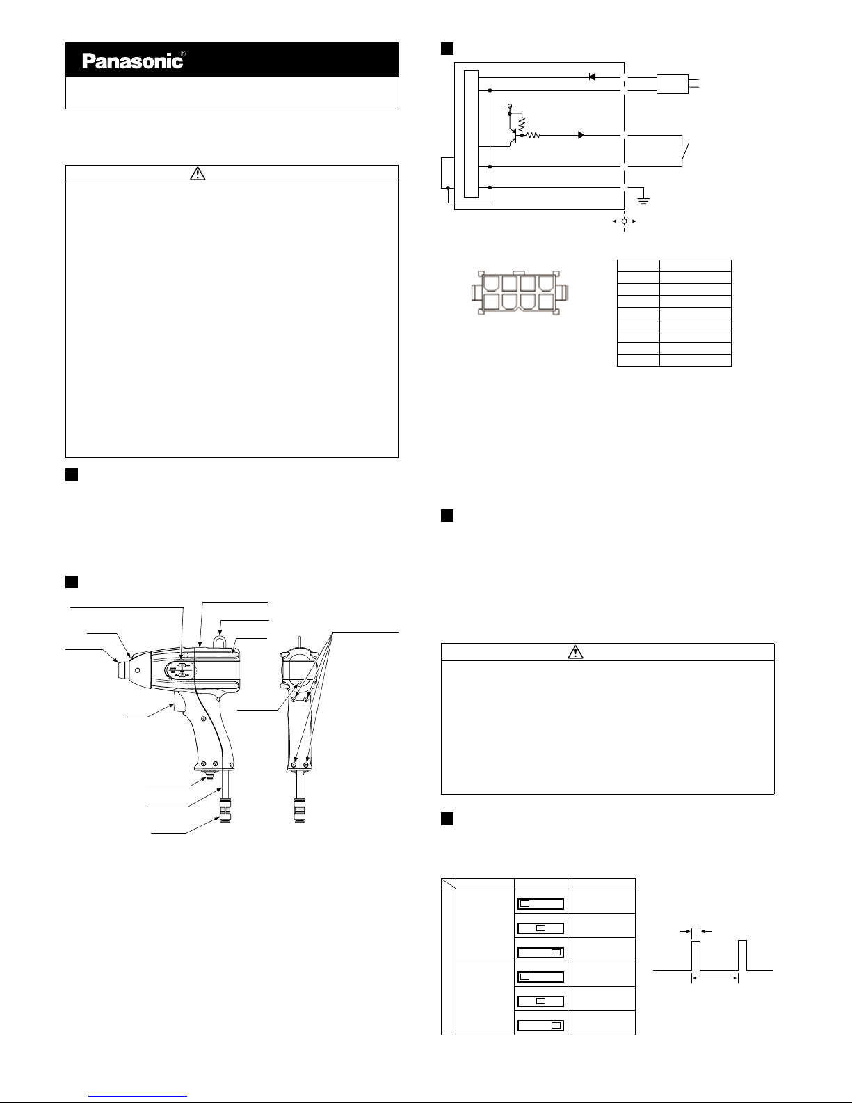
3 I/O circuit DIAGRAM
D
⑤
①
③
②
⑧
Main circuit
AC adapter (accessory)
24V
0V
5V
4.7kΩ
External input
Switch for external input
Nozzle
COM (-)
[connected internally to 0V,COM (-) and
nozzle metallic parts]
GND
D: Power supply reverse connection
protection diode
Internal circuit Users’ circuit
100 to 240V AC
● Pin layout for AC adapter power
supply connector
(From cable insertion side)
①
②
③④
⑧ ⑤
⑦
⑥
● Terminal block diagram
Terminal No. Terminal name
1 0V
2 COM (-)
3 External input
4 N.C. (not used)
5 24V
6 N.C. (not used)
7 N.C. (not used)
8 GND
● 1 and 5 are connected to the AC adapter.
● Use the accessory connector wiring terminal to connect external input or GND.
● When using external input
When using external input, ionized air discharging can be carried out using the
same ON/OFF operations as trigger input.
Note: The COM (-) terminal which uses external input is connected internally to 0V, the GND terminal and the nozzle
metallic parts. If external input ON/OFF switching is carried out using an external control device instead of an independent mechanical-type switch, or if the 0V potential of the external control device and the grounding potential of the place of use are different (such as in the case of positive power supply grounding), the external control
device used for external input should have an insulated on/off procedure for the 0V line (such as photocoupler
output or relay output) in order to prevent short-circuits from occurring.
4 WIRING / PIPING
● Use the accessory relay cable to connect the main unit and the AC adapter.
● Use the accessory straight joint to connect a suitable air tube to the main unit.
● Connect the GND terminal of this product to a secure ground when using it.
● Since the pressure will drop when the air piping
from the main pressure supply is
extended
or pneumatie-components (e.g., needle valve, speed-controler, minil-
ter) are added, keep an eye on the pressure supply to
the ionizer maiking sure it
isn’t in short supply
. For the pneumatic-components, select those that can accom-
modate the air supply ow rate.
* The air supplied should be dry, clean air (air drier: dew point approx. -20°C, air l-
ter: mesh size of approx. 0.01μm).
CAUTION
● Turn off the power and air and make sure that the supply of air has been fully
shut off before carrying out any wire and tube connection work. If this is not
done, accidents or problems with operation may occur.
● The metal parts of the nozzle are connected inside the product to the 0V and
GND terminal. Do not connect it to objects with a different electrical potential
such as the conductive parts of external devices. If the supplied air contains
any
particles
other than air or any corrosive gases, accidents or problems with opera-
tion may occur. In addition, if air which contains impurities
such as carbon dust
or air which
contains moisture or oil is used, accidents or problems with opera-
tion may also occur.
● Do not modify the nozzle or install the nozzle to any other appliances, otherwise
correct charge removal performance may not be obtained, and accidents or
problems with operation may occur
.
5 OPERATION
1. Use the mode select switches to select the required settings.
2. Face the ionizer toward the electrostatically-charged object and pull the trigger.
When the trigger is pulled, dust removal operation will start, and when
the trigger
is released, dust removal operation will stop.
Name Position Details
Pulse
width
Cycle
Mode select switches
Pulse air mode
selection
12 CONT
Pulse 1 (*)
12 CONT
Pulse 2 (*)
12 CONT
Continuous
LED illumination
mode selection
ON SYNC OFF
Always ON
ON SYNC OFF
Synchronized with
trigger
ON SYNC OFF
Always OFF
*:
Pulse 1: Pulse ionized air emission cycle approx. 100ms, pulse width approx. 50ms
Pulse 2: Pulse ionized air emission cycle approx. 100ms, pulse width approx. 10ms
Ramco National
www.PanasonicSensors.com
1-800-280-6933
6 CARE AND MAINTENANCE
●
Be sure to turn off the power and air before carrying out cleaning and maintenance.
● Make sure that the supply of air has been fully shut off and that all pressures at
the product and inside the tubes are at zero before continuing. If this is not done,
air pressure may cause operating problems or accidents.
●
The discharge needle has a sharp point, so be very careful when cleaning the needle.
●
Clean the discharge needle regularly about once a week, otherwise optimum charge removal performance may not be obtained and accidents or operating problems may occur.
●
The discharge needle is a consumable part. If charge removal performance does not return
to normal after the discharge needle has been cleaned, then the needle should be replaced.
Cleaning and replacing the discharge needle
1.
Turn off the power and check that the air pressure inside the air tube has dropped to zero.
2. Remove the nozzle guard, turn the nozzle counterclockwise and remove it.
3. Remove the insulating pipe and the attachment.
4.
When carrying out cleaning, use a cotton swab moistened in alcohol or similar to remove any
dirt from the needle and the area around it. (If replacing the discharge needle, use needle nose
pliers or a similar tool to pull out the needle, and then insert a new needle as far as it will go.)
5. After cleaning or replacing the needle, return the attachment, insulating pipe and
nozzle to their normal installation positions. Turn the nozzle clockwise to install it.
The tightening torque for the nozzle at this time should be 3N•m or less.
Lastly, afx the nozzle guard.
*:
Do not touch the tip of the discharge needle against tools or any other hard surfaces. If
the discharge needle is damaged, optimum charge removal performance may not be
obtained and accidents or problems with operation may occur. In addition, do not touch
the stopper ring area, otherwise the stopper ring may slip out of position, and it may
not be possible to reinstall it. When handling the discharge needle with tools, hold the
discharge needle at the middle and avoid applying excessive force to the needle.
Note: When installing the attachment, make sure that it is facing the correct direction. If it is installed so that it is facing
the wrong direction, it will not be possible to fully tighten the nozzle.
Insulating pipe
Stopper ring
Discharge needle (*)
Attachment (Note)
Nozzle
Nozzle guard
*: Option (sold separately)
EC-GANT : Discharge needle 1 pc.
● The solenoid valve is a consumable part (open/close operations: ap-
prox. 8,000,000). If it no longer opens and closes normally, stop using
the ionizer and replace the solenoid valve.
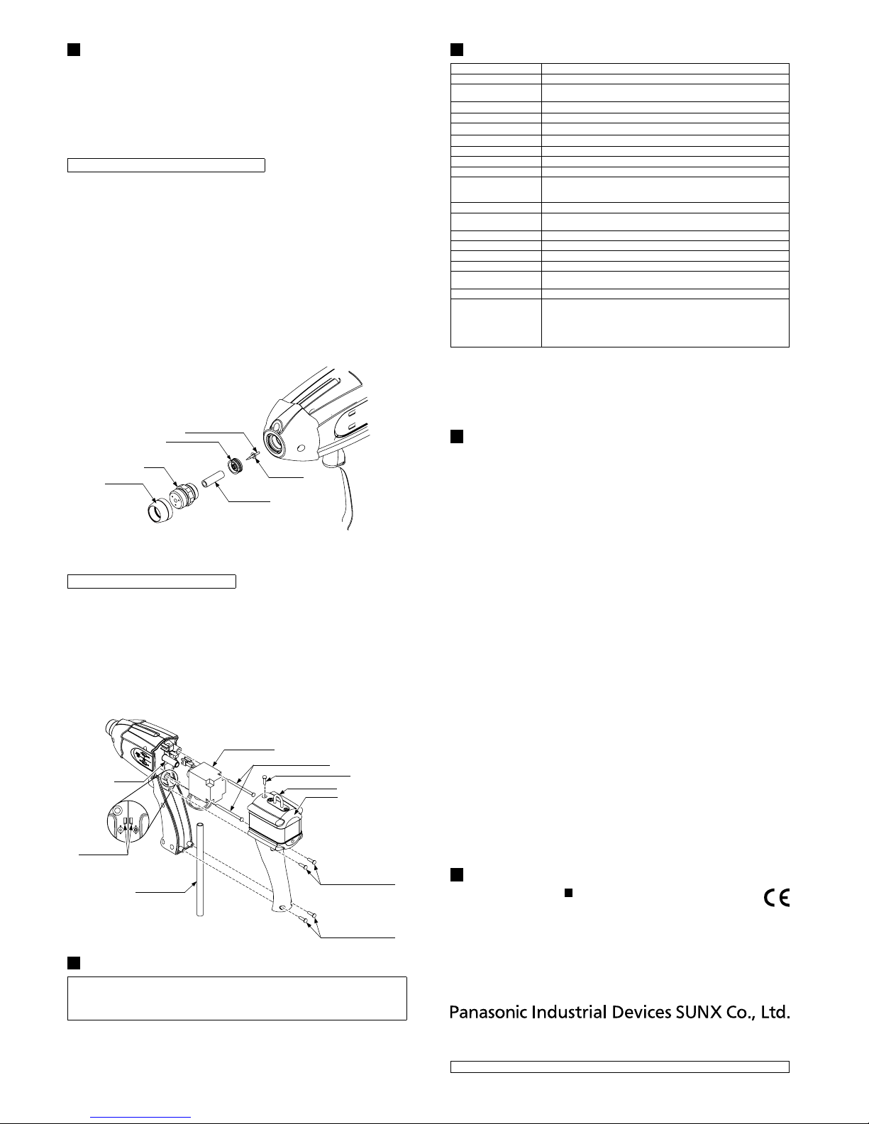
Solenoid valve replacement procedure
1. Check that the power is turned off and that the air pressure inside the air tube has
dropped to zero.
2.
Remove the back cover. Remove the four M3 mounting screws. (A in diagram below)
3. Disconnect the air tube from the solenoid valve. (B in diagram below)
4. Disconnect the solenoid valve lead wire connector.
5. Remove the two M3 mounting screws. (C in diagram below)
6. Disconnect the air pipe from the solenoid valve. (D in diagram below)
7. Install the new solenoid valve, and then install the M3×45 mounting screws and
connect the air tubes and the solenoid valve lead wire connector. Tighten the
M3×45 mounting screws at a torque of 0.2N•m or less.
8.
Install the back cover. Let the lead wire pass the lead wire holder, and make sure that the cov-
er will not catch lead wire. Tighten the M3×10 mounting screws at a torque of 0.4N•m or less.
*: Option (sold separately)
EC-GAV: Solenoid valve 1 pc.
D: Air pipe
Solenoid valve (*)
B: ø8mm air tube
Lead wire holder
C: M3×4.5 mounting screw
A: M3×10 mounting screw
Fixed metal hook
Back cover
A: M3×10 mounting screw
(Tapping screw)
A: M3×10 mounting screw
(Tapping screw)
7 TROUBLESHOOTING
When an error is detected, the white LED ashes. (It also ashes even when the
LED illumination mode is set to “Always OFF”.) If the white LED is ashing, carry out
the following checking operations. When checking the discharge area, always be
sure to turn off the power before carrying out the checking.
● Turn off the power and check that the tip of the needle is intact and that there is
no dirt on it, and that the needle is installed correctly.
● Check that there are no foreign objects inside the nozzle.
● Check that the nozzle is installed correctly. (Including the attachment and the insulating pipe)
● Check that the air pressure is within the specication range.
8 SPECIFICATIONS
Type Pulse Air-gun Ionizer
Model No. EC-G02
Charge removal time
(±1,000V → ±100V)
0.5 sec. or less (Note 1)
Ion balance ±10V or less (Note 1)
Power supply voltage Accessory AC adapter INPUT: 100 to 240V AC±10% 50/60Hz (OUTPUT: 24V DC)
Power consumption 30VA or less
Discharge method High-frequency AC method
Discharge output voltage 2000V approx.
Ozone generation 0.02ppm or less (Note 2)
Applicable uid Air (dried clean air)
External input
Ionized air emission operation ON/OFF using OR control with trigger switch
• Ionized air emission operation ON: Short-circuited to COM (-)
• Ionized air emission operation OFF: Open
Indicators Valve illumination: Illuminated when solenoid valve is ON (open) (orange LED)
Error detection function
When an abnormal discharge (short-circuited, etc.) occurs, discharge is forcibly stopped
and the spotlight ashes (reset when the power is turned off and back on) (N
ote 3)
Ambient temperature 0 to + 50°C (No dew condensation), AC adapter: 0 to +40°C
Ambient humidity 35% to 65% RH (No dew condensation)
Supplied air ow Max. 300 ℓ/min. (ANR) or less
Air pressure range 0.05 to 0.50 MPa
Material
Enclosure: ABS, Nozzle: Stainless steel, Discharge needle: Tungsten
Nozzle guard: NBR
Weight 270g approx. (main unit only)
Accessories
• AC adapter 1 pc.
•
Exdusive intermediate cable (oil-proof / heat-proof / winding-proof type) length 2m: 1 pc.
• Straight joints
Tube outer diameter ø8mm-ø8mm compatible type 1 pc. (Note 4)
Tube outer diameter ø8mm-ø6mm compatible type 1 pc.
• Connector connection terminal (manufactured by Molex) 3 pcs.
Notes: 1) Typical value for continuous pulse air mode at 100mm from end of discharge nozzle at an applied air pres-
sure of 0.50MPa
2) Typical value for continuous pulse air mode at 300mm from end of discharge nozzle at an applied air pressure of 0.25MPa
3) Once an error is detected, the error status is maintained until the power is turned off and back on again.
Remove the cause of the error and then turn the power back on.
If the cause of the error is not removed, the error will occur once more.
4) At the time of shipment from the factory, ø8mm-ø8mm type is attached.
9 CAUTIONS
● This product has been developed / produced for industrial use only.
●
Do not use this product for any purpose other than charge removal and dust removal.
● Do not use this product in enviroments which are outside the specication range,
otherwise operating problems or damage may occur. In addition, the operating life
of the product may become signicantly reduced.
● Never disassemble, repair or modify this product, otherwise operating problems or
accidents may occur.
● Do not dispose of this product by burning it, otherwise it may explode or toxic
fumes may be generated.
● This product generates ozone, so be sure to provide adequate ventilation if using
it in a conned space.
● Do not run the wires together with high-voltage lines or power lines or put them in
the same raceway. This can cause malfunction due to induction.
● Be sure to turn off the air and the power supply before carrying out any cable con-
nection or inspection work. If this is not done, operating problems, damage or
electric shocks may occur.
● After connecting the cables, check that the air piping and power supply connec-
tions are correct before turning on the power. If the wires or cables are connected
incorrectly, operating problems or accidents may occur.
● Verify that the supply voltage variation is within the rating.
● Do not turn the power back on immediately after it has been turned off, otherwise
operating problems or accidents may occur. In addition, the operating life of the
product may become signicantly reduced. Wait at least 2 seconds before turning
the power back on again.
● Do not use the power plug of the AC adapter if it has become dusty, otherwise re
may occur.
● The air tube or cable may be broken if excessive tension or other stress is applied
to the air tube and cable. Consider appropriate margins of the air tube and cable
within the work area when using them.
● Do not use any cables which have any damage (such as splitting or cracking),
otherwise operating problems or accidents may occur.
● Avoid using the product in places where there are high levels of steam or dust in
the air or where it might be directly exposed to water, oil or welding spatter.
● Do not touch the discharge needle with hard objects such as tools. If the dis-
charge needle becomes broken, it will not provide sufcient charge removal performance, and moreover operating problems or accidents may occur.
● If this product ceases functioning or is no longer required, dispose of it according
to appropriate local waste disposal regulations.
● This product is a high-precision device, and should be handled with care.
10
INTENDED PRODUCTS FOR CE MARKING
●
The models listed under “
8
SPECIFICATIONS” come with CE Marking.
As for all other models, please contact our ofce.
● Contact for CE
Panasonic Marketing Europe GmbH Panasonic Testing Center
Winsbergring 15, 22525 Hamburg,Germany
http://panasonic.net/id/pidsx/global
Overseas Sales Division (Head Ofce)
2431-1 Ushiyama-cho, Kasugai-shi, Aichi, 486-0901, Japan
Phone: +81-568-33-7861 FAX: +81-568-33-8591
About our sale network, please visit our website.
PRINTED IN JAPAN © Panasonic Industrial Devices SUNX Co., Ltd. 2014
Ramco National
www.PanasonicSensors.com
1-800-280-6933
 Loading...