

Panasonic MEW01349, EBL512 G3 V1.1.x Operating Instructions Manual

Operating Instructions
MEW01349
Revision -
Fire Alarm System EBL512 G3
V1.1.x
Author: Jan Pettersson
Date of issue: 2011-02-18
Date of rev:

This page has deliberately been left blank.

Panasonic Electric Works Nordic AB
MEW01349 Rev: - Operating Instructions Fire alarm system EBL512 G3, V1.1.x
1
Table of contents
1 Introduction________________________________ 6
2 Definitions / Explanations ____________________ 8
2.1 PEWN AB ________________________________________ 8
2.2 Alarm points ______________________________________ 8
2.2.1 Smoke detector ________________________________ 8
2.2.2 Sensor _______________________________________ 8
2.2.3 Analog detector ________________________________ 8
2.2.4 Analog (Sensor) Base (ASB) _____________________ 8
2.2.5 Conventional detector ___________________________ 8
2.2.6 (Conventional Detector) Base (CDB) _______________ 8
2.2.7 Addressable ___________________________________ 8
2.2.8 Conventional zone line input / External line __________ 9
2.3 Output unit _______________________________________ 9
2.4 Output / Control output ______________________________ 9
2.5 Short circuit isolator (ISO) ___________________________ 9
2.6 Display unit (DU) __________________________________ 9
2.7 COM loop ________________________________________ 9
2.8 Control Unit / C.U. / C.I.E. ___________________________ 9
2.9 Fire Brigade Panel (FBP) ____________________________ 9
2.10 Control panel (CP) _________________________________ 9
2.11 System __________________________________________ 10
2.12 Network / TLON® / LonWorks® / Echelon / Node / TLON
Conn. board / Gateway / Sub net / Backbone net / Router / Repeater 10
2.13 LED ____________________________________________ 10
2.14 External Indicator (LED) ___________________________ 10
2.15 Display / LCD ____________________________________ 10
2.16 Door open (Door / Key switch) _______________________ 10
2.17 Site Specific Data (SSD) ____________________________ 11
2.18 Software (S/W) / System program ____________________ 11
3 Overview _________________________________ 12
3.1 The EBL512 G3 system ____________________________ 12
3.1.1 Printer ______________________________________ 12
3.1.2 Expansion boards _____________________________ 12
3.1.3 Power supply _________________________________ 12
3.2 S/W versions _____________________________________ 13
3.3 Documents ______________________________________ 13
3.4 Applications _____________________________________ 13
3.5 PC S/W _________________________________________ 13
3.5.1 WinG3 ______________________________________ 13
3.5.2 TLON Manager _______________________________ 14
3.5.3 WebG3 Config tool ____________________________ 14
4 Control Unit ______________________________ 15

Panasonic Electric Works Nordic AB
MEW01349 Rev: - Operating Instructions Fire alarm system EBL512 G3, V1.1.x
2
5 LED indicators and push buttons _____________ 17
6 The display (LCD) _________________________ 21
6.1 Areas in the display ________________________________ 21
6.2 The symbol area __________________________________ 21
6.3 The information area priority order ____________________ 22
6.4 System information in the LCD ______________________ 23
6.4.1 User definable system information ________________ 23
7 Access levels _______________________________ 24
7.1 Access level 1 ____________________________________ 25
7.2 Access level 2A ___________________________________ 25
7.3 Access level 2B ___________________________________ 26
7.4 Access level 3A ___________________________________ 27
7.5 Access level 3B ___________________________________ 27
7.6 Access level 4 ____________________________________ 27
8 "Silence Alarm devices"_____________________ 28
8.1 Silence alarm devices (inside switch) __________________ 28
8.2 New Zealand FB Silence switch (outside switch) _________ 29
9 Disable / Re-enable alarm devices _____________ 31
10 "Silence buzzer" ___________________________ 32
11 Disable / Re-enable all control, extinguishing,
ventilation and interlocking outputs ________________ 33
12 Evacuate__________________________________ 34
13 Open door ________________________________ 35
13.1 Outputs for routing equipment (Fire brigade tx and Fault tx) 35
14 Technical number / Presentation number ______ 36
14.1 Technical number for COM loop units _________________ 36
14.2 Presentation number _______________________________ 37
15 Alarm types _______________________________ 38
15.1 Pre-warning ______________________________________ 38
15.2 Fire alarm _______________________________________ 39
15.2.1 Enter the menu during fire alarm _________________ 42
15.2.2 Acknowledged and Isolated alarm ________________ 43
15.3 Heavy smoke alarm / Heavy heat alarm ________________ 43
15.4 Alert Annunciation alarm (AA alarm) _________________ 44
15.5 Key cabinet alarm _________________________________ 45
15.5.1 Key cabinet opened before a fire alarm_____________ 45
15.5.2 Key cabinet opened in conjunction with a fire alarm __ 45
15.6 Co-incidence alarm (2-address / -zone dependence) _______ 46
15.7 Alarm Acknowledgement Facility (AAF) _______________ 47
15.8 Quiet alarm ______________________________________ 47
16 Alarm reset _______________________________ 49
16.1 Pre-warning reset _________________________________ 49

Panasonic Electric Works Nordic AB
MEW01349 Rev: - Operating Instructions Fire alarm system EBL512 G3, V1.1.x
3
16.2 Fire alarm reset ___________________________________ 49
16.2.1 All _________________________________________ 49
16.2.2 Single_______________________________________ 49
16.2.3 Single with automatic disablement ________________ 50
16.2.4 Acknowledged and Isolated alarm ________________ 50
16.3 Heavy smoke / heat alarm reset ______________________ 50
16.4 Alert Annunciation ________________________________ 50
16.5 Key cabinet alarm reset _____________________________ 51
16.6 Co-incidence alarm ________________________________ 51
16.7 Alarm Acknowledgement Facility (AAF) reset __________ 51
16.8 Quiet alarm reset __________________________________ 51
17 Fault _____________________________________ 52
17.1 Fault messages ___________________________________ 54
17.2 Fault acknowledge ________________________________ 69
18 Commissioning an installation _______________ 71
18.1 Single Control Unit ________________________________ 71
18.2 Control Units in a TLON network ____________________ 72
18.2.1 TLON network installation ______________________ 72
18.3 Add a Control Unit in a TLON network ________________ 73
18.4 Make two TLON networks one. ______________________ 73
18.5 Delete a Control Unit in a TLON network ______________ 73
19 Programming (SSD download) _______________ 75
19.1 Check Loop ______________________________________ 75
19.2 Single Control Unit ________________________________ 75
19.3 Control Units in a TLON network ____________________ 76
19.4 User definable text messages download ________________ 76
20 New system program (S/W) version download __ 77
20.1 Single control unit (c.i.e.) ___________________________ 77
20.2 Control Units in a TLON network ____________________ 79
21 Upgrade number of alarm points _____________ 80
21.1 Control Units in a TLON network ____________________ 80
22 Restart ___________________________________ 81
23 Access ____________________________________ 85
24 Perform monthly test (H1) ___________________ 87
25 Disable or re-enable (H2) ____________________ 90
25.1 Disable zone (H2/B1) ______________________________ 91
25.2 Disable zone / address (H2/B2) _______________________ 92
25.3 Disable output (H2/B3) _____________________________ 94
25.4 Re-enable zone (H2/B4) ____________________________ 95
25.5 Re-enable zone / address (H2/B5) _____________________ 96
25.6 Re-enable output (H2/B6) ___________________________ 97
25.7 Disable / re-enable output type (H2/B7) ________________ 98
25.8 Disable / re-enable alarm devices (H2/B8) _____________ 100

Panasonic Electric Works Nordic AB
MEW01349 Rev: - Operating Instructions Fire alarm system EBL512 G3, V1.1.x
4
25.9 Disable / re-enable routing equipment (H2/B9) _________ 102
25.10 De-activate Alert Annunciation function (H2/B10) ____ 103
26 Set calendar and clock (H3) _________________ 104
27 Present system status (H4) __________________ 105
27.1 Disablement (H4/U1) _____________________________ 105
27.2 Disablement by time channel (H4/U2) ________________ 106
27.3 Open doors (H4/U3) ______________________________ 107
27.4 Sensor values (H4/U4) ____________________________ 108
27.4.1 Reset of a week average sensor value _____________ 110
27.5 Sensors activating SERVICE signal (H4/U5) ___________ 111
27.6 Event log (H4/U6) ________________________________ 112
27.7 Show information (H4/U7) _________________________ 112
28 Service (H5) ______________________________ 115
28.1 Access code for service / maintenance (H5 and H8)______ 116
28.2 Calibration of supervised outputs (H5/A1) _____________ 117
28.3 Sensitive fault detection mode (H5/A2) _______________ 118
28.4 Service mode for COM-loop (H5/A3) ________________ 119
28.5 Display current consumption in unit (H5/A4) ___________ 121
28.6 Display current consumption COM-loop (H5/A5) _______ 122
28.7 Display statistics for communication (H5/A6) __________ 123
28.8 Activate address setting mode for DU (H5/A7) _________ 125
29 FAULT Acknowledge (H6) _________________ 126
30 Perform ZONE TEST (Test mode) (H7) ______ 127
31 Maintenance (H8) _________________________ 129
31.1 Access code for service / maintenance ________________ 129
31.2 Disconnect loop (H8/S1) ___________________________ 129
31.3 Re-connect loop (H8/S2) ___________________________ 131
31.4 Acknowledge SERVICE signal (H8/S3) _______________ 132
31.5 Clear weekly average (H8/S4) ______________________ 134
31.6 Test of alarm devices (H8/S5) _______________________ 135
31.7 Safe shut down of control unit (H8/S6) _______________ 137
31.8 Activate address in alarm mode (H8/S7) ______________ 139
31.9 Synchronize the control units (H8/S8) ________________ 141
31.10 Change code for service / maintenance (H8/S9) _______ 143
31.11 Change code for PC-communication (H8/S10) _______ 144
32 Interlocking outputs and inputs (H9) _________ 145
32.1 Activated interlocking outputs / inputs (H9/C1) _________ 145
32.2 Activate interlocking output (H9/C2) _________________ 146
32.3 Reset interlocking output (H9/C3) ___________________ 147
32.4 Disable interlocking output (H9/C4) __________________ 148
32.5 Re-enable interlocking output (H9/C5) ________________ 149
33 Change access code for daily duties (H10) _____ 150
34 Annual control ___________________________ 151

Panasonic Electric Works Nordic AB
MEW01349 Rev: - Operating Instructions Fire alarm system EBL512 G3, V1.1.x
5
35 How to change paper in the printer __________ 152
36 Replacing a TLON connection board and/or the
Main board____________________________________ 153
37 Battery maintenance _______________________ 154
38 How to avoid unnecessary (nuisance) fire alarms 155
39 Information regarding radioactive radiation source157
40 Revision history ___________________________ 158

Panasonic Electric Works Nordic AB
MEW01349 Rev: - Operating Instructions Fire alarm system EBL512 G3, V1.1.x
6
1 Introduction
EBL512 G3 Operating Instructions is a document intended to be used
by the end-user and the fire brigade personnel as well as service /
commissioning engineers.
Due to continual development and improvement, different S/W
versions are to be found. This document is valid for S/W version
1.1.x. On the date / rev date of this document x = 0.
Since the EBL512 G3 control unit (c.i.e.) is produced for many
countries the look, the texts, the functions, etc. might vary.
Products
Consists of one or more parts (HW) according to a Product Parts
List. A product has:
a type number
5000 EBL512 G3 c.i.e. Configured for 128, 256 or 512 alarm
points and with or without printer depending on article number.
5001 EBL512 G3 c.i.e. No front panel and no Plexiglas in the
door. Configured for 128, 256 or 512 alarm points depending
on the article number.
an article number is often the same as the type no. but a country
code can be added (e.g. SE for Sweden). If also the letters PRT
are added in the article number the product comes with a printer.
If digits are added to the article number they are showing the
number of alarm points configured (e.g. 5000PRTSE-128).
a product name (e.g. EBL512 G3 CU, 128 alarm points, with
printer)
HW
A HW (e.g. a printed circuit board) has:
a type number (e.g. 5010)
an article number, often = the type no. and sometimes is a
country code added (e.g. 5010SE)
a product name (e.g. Main Board 128 alarm points)
a p.c.b. number (e.g. 9290-3B) and can also have a configuration
(e.g. CFG: 2) and a revision (e.g. REV: 2)
sometimes a S/W
S/W
A S/W has:
a version number (e.g. V1.1.x)

Panasonic Electric Works Nordic AB
MEW01349 Rev: - Operating Instructions Fire alarm system EBL512 G3, V1.1.x
7
sometimes additional information, such as Convention (different
functions / facilities), Language, Number of addresses, etc.
PC S/W
A PC S/W is a program used for programming, commissioning, etc. It
has a version number.

Panasonic Electric Works Nordic AB
MEW01349 Rev: - Operating Instructions Fire alarm system EBL512 G3, V1.1.x
8
2 Definitions / Explanations
Definitions / explanations / abbreviations / etc. frequently used or not
explained elsewhere in the document.
2.1 PEWN AB
Panasonic Electric Works Nordic AB
2.2 Alarm points
Units, which can generate a fire alarm (in the control unit), i.e. analog
detectors (sensors), conventional detectors, manual call points, etc.
2.2.1 Smoke detector
Analog and conventional photoelectric (optical) smoke detectors are
available.
2.2.2 Sensor
Sensor = Analog detector
2.2.3 Analog detector
Contains an A/D-converter. The Control Unit pick up the digital
values ("sensor values") for each detector individually. All
evaluations and "decisions" are then made in the c.i.e. Analog
detectors are addressable – an address setting tool is used for detector
types 33xx / 430x.
An analog detector has to be plugged in an analog sensor base (ASB).
2.2.4 Analog (Sensor) Base (ASB)
A sensor is plugged in an ASB, which is connected to a COM loop
(see below).
2.2.5 Conventional detector
Detector with only two statuses, i.e. normal and fire alarm. The
detector contains a closing contact and a series alarm resistor.
Normally plugged in a conventional detector base CDB (see below)
connected to a conventional zone line input, with an end-of-line
device. Some types are connected directly on zone line.
2.2.6 (Conventional Detector) Base (CDB)
A conventional detector is plugged in a CDB, connected to a
conventional zone line input.
2.2.7 Addressable
A unit with a built-in address device, i.e. each unit is individually
identified, handled and indicated in the c.i.e.
(The unit can be an I/O unit with a zone line input, to which one or
more conventional "alarm points" can be connected.)

Panasonic Electric Works Nordic AB
MEW01349 Rev: - Operating Instructions Fire alarm system EBL512 G3, V1.1.x
9
2.2.8 Conventional zone line input / External line
Input intended for one or more conventional alarm points. End-of-line
device in the last alarm point.
2.3 Output unit
Addressable unit with programmable control outputs. Connected to a
COM loop (see below).
2.4 Output / Control output
Defined or programmable function. Relay output or voltage output
(supervised / monitored), in the c.i.e. or an output unit.
2.5 Short circuit isolator (ISO)
Addressable unit for automatic disconnection of a part (segment) of a
COM loop (see below) in case of a short circuit on the loop.
(According to EN54-2: One ISO is required per 32 alarm points on
the COM loop.)
2.6 Display unit (DU)
Addressable unit for fire alarm presentation (incl. user definable text
messages, if programmed).
2.7 COM loop
Loop = a cable, with two wires, to which all the addressable units can
be connected. Starts in the c.i.e. and it returns back to the c.i.e.
2.8 Control Unit / C.U. / C.I.E.
Control Unit = Control and Indicating Equipment = Unit to which the
alarm points are connected (via a COM loop). Indicates fire alarm,
fault condition, etc. Fire Brigade Panel & Control Panel (see below)
included or not included. Printer included or not included.
2.9 Fire Brigade Panel (FBP)
Unit intended for fire alarm presentation, etc. for the fire brigade
personnel. Can be a part of the control unit (front) or a separate unit
(external FBP).
In the ext. FBP, a printer can be included or not included.
2.10 Control panel (CP)
A part of the control unit (front), intended for the building occupier,
service personnel, etc., to "communicate" with the control unit /
system.

Panasonic Electric Works Nordic AB
MEW01349 Rev: - Operating Instructions Fire alarm system EBL512 G3, V1.1.x
10
2.11 System
Several control units connected via a TLON network (co-operating
control units).
2.12 Network / TLON® / LonWorks® / Echelon /
Node / TLON Conn. board / Gateway / Sub
net / Backbone net / Router / Repeater
Brief explanations to the words/expressions to be found in connection
with a "network". See also separate TLON Technical description.
TLON® = TeleLarm Local Operating Network = a LonWorks®- based
network for communication between several units/nodes. The
protocol is LonTalk and the transmission works with doublyterminated bus topology (Echelon FTT-10). To connect a control unit
to the network, a TLON connection board is plugged in the control
unit. (Old installations: Some control units, not prepared for network
connection, could be connected via a serial interface and a Gateway).
A network can be one sub net (FTT-10) or several sub nets, connected
via routers. (In the TLON Network a sub net = a channel.)
Routers are also used to increase the maximum cable length, node to
node, in a network.
All network programming (configuration) are made with the PC
program "TLON Manager".
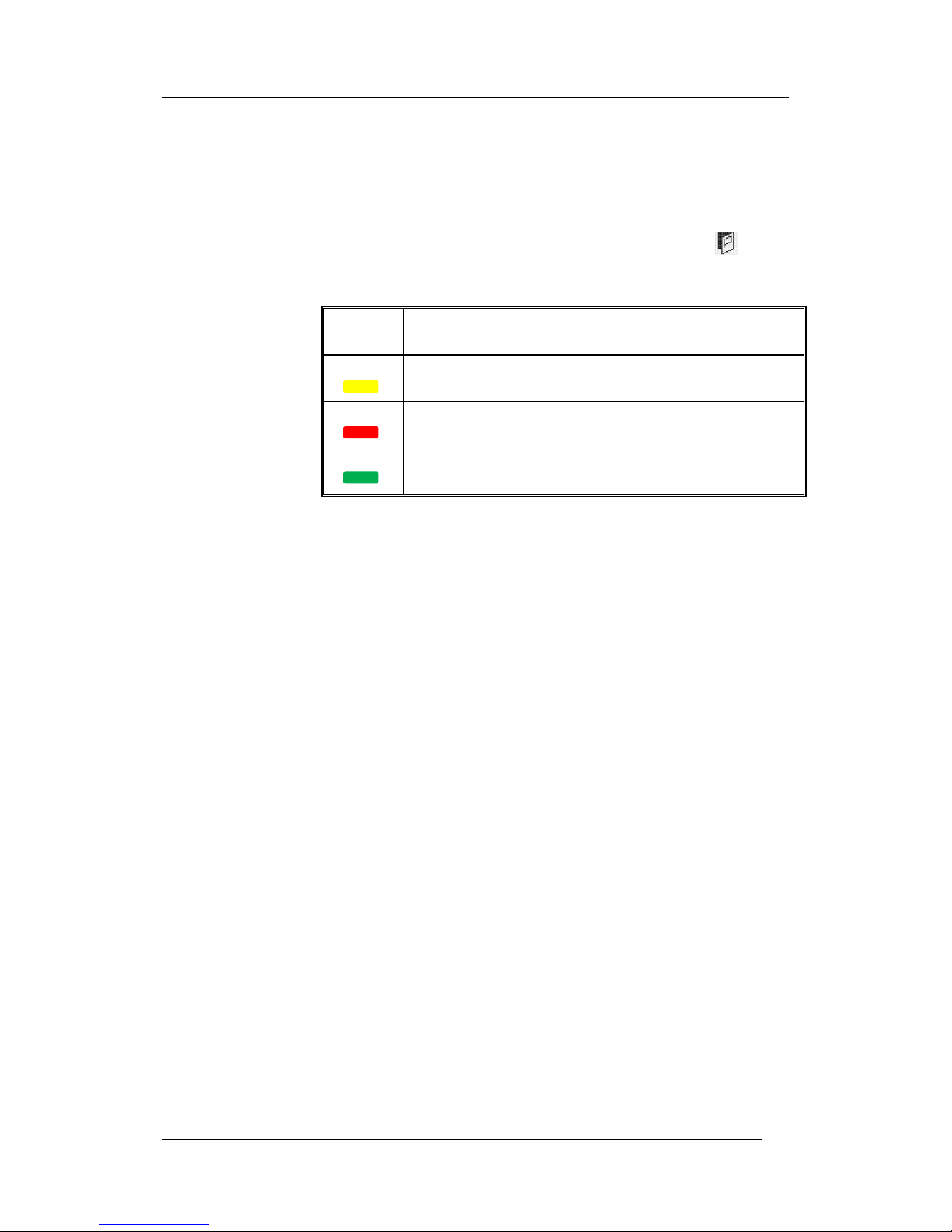
2.13 LED
LED (Light Emitting Diode) = Yellow, green or red optical indicator
("lamp").
2.14 External Indicator (LED)
A unit with an LED. Connected to an ASB, CDB or a detector with a
built-in LED. Old installations: Also connected to an ADB.
Lit when the built-in LED is lit.
2.15 Display / LCD
LCD (Liquid Crystal Display) = Display (in the c.i.e. or Display unit)
for presentation of fire alarms, fault messages, etc. a graphical
monochrome LCD (320 x 240 dots) and backlight.
2.16 Door open (Door / Key switch)
In EBL512 G3 there is a door switch, which is activated when the
control unit door is open. In some other units this door switch is
replaced with a key switch.
When the door is open a message "Door is open in this unit" is shown
in the LCD.

Panasonic Electric Works Nordic AB
MEW01349 Rev: - Operating Instructions Fire alarm system EBL512 G3, V1.1.x
11
2.17 Site Specific Data (SSD)
The SSD is unique for each installation. All alarm points,
presentation numbers, user definable text messages, programmable
outputs, etc. are created in the PC program WinG3 and also
downloaded in EBL512 G3 with WinG3.
2.18 Software (S/W) / System program
The S/W makes the control unit (the microprocessor) work. It is
factory downloaded but a new version can be downloaded in EBL512
G3 on site.

Panasonic Electric Works Nordic AB
MEW01349 Rev: - Operating Instructions Fire alarm system EBL512 G3, V1.1.x
12
3 Overview
3.1 The EBL512 G3 system
EBL512 G3 is a microprocessor controlled intelligent fire alarm
system, intended for analog addressable smoke detectors, as well as
conventional detectors and manual call points. Programmable control
outputs and output units are available. Up to 1020 addresses (of
which up to 512 can be alarm points) can be connected to each control
unit (c.i.e.) - according to EN54-2.
EBL512 G3 is available in several types, versions and configurations.
It can be connected to a TLON network, i.e. in a "system", with up to
30 control units. Each control unit has access to all information.
Product type no.
Product name
5000
EBL512 G3 c.i.e. With or without a printer.
With front and display.
5001
EBL512 G3 c.i.e.
Without front, display and printer. No door.
EBL512 G3 is designed according to the European standard EN54,
part 2 and 4. The Swedish front conforms to SS3654.
3.1.1 Printer
The control unit EBL512 G3 type 5000 can be delivered with a printer
("PRN" included in the article number) or without a printer.1
In Ext. Fire Brigade Panel 1826 it is possible to mount an optional
Printer 1535.
3.1.2 Expansion boards
In the control unit (c.i.e.) it is possible to mount up to six expansion
boards. The following types are available:
Product type no.
Product name
Note
4580
8 zones expansion board
4581
8 relay outputs expansion board
4583
Inputs and outputs expansion board
Regarding the expansion boards, see also the EBL512 G3 Planning
Instructions and drawings.
3.1.3 Power supply
The main power source is a built-in switched power supply (rectifier)
5037, 230 V AC / 24 V DC, 6.5 A.
The second power source is a backup battery (2 x 12 V). In the c.i.e.
1
Printer 5058 is a spare part for the c.i.e. type 5000 with a printer, i.e. it
comes without a mounting frame etc.

Panasonic Electric Works Nordic AB
MEW01349 Rev: - Operating Instructions Fire alarm system EBL512 G3, V1.1.x
13
is space for two 27 Ah batteries. Larger batteries (up to 65 Ah) have
to be placed outside the c.i.e.
The batteries and the power supply are connected to the Main board
(5010), which handles the charging of the batteries, etc. See the
EBL512 G3 Planning Instructions, chapter "Power supply" for more
information.
3.2 S/W versions
Due to continual development and improvement, different S/W
versions can be found. When installing a new control unit in a system
with "older" control units, you might have to update the S/W in the
old control units. The same S/W version is required in all control
units.
3.3 Documents
The following documents are available:
Planning instructions MEW01182
Operating Instructions
Drawings
Normally, information found in one of the documents is not found in
another document, i.e. the documents complement each other.
3.4 Applications
The EBL512 G3 system is intended for small, medium and large
installations. The intelligent control units offer the system designer
and end user a technically sophisticated range of facilities and
functions. Programming (PC software WinG3 and TLON Manager)
and commissioning of the control unit / system is very easy.
Start with one control unit and then later when it is required, add more
units. The TLON network makes it possible to install the control units
in one building or in many buildings.
3.5 PC S/W
3.5.1 WinG3
WinG3 is used for programming and commissioning of one or more
control units:
create / download / backup (upload) of site specific data (SSD)
download of software / settings / conventions / configurations /
control unit & system properties / etc.
create / download the user definable text messages (alarm texts)
shown in the display in the C.U. and ext. FBP / Display units.
WinG3 shall have the same (or higher) version number as the EBL512
G3 software version number (e.g. 1.0.x and 1.0.x respectively).
Backup require the same version number (in WinG3 and in EBL512
G3). Old SSD files can be opened and saved in a newer (higher)
version of WinG3 and thereafter downloaded.

Panasonic Electric Works Nordic AB
MEW01349 Rev: - Operating Instructions Fire alarm system EBL512 G3, V1.1.x
14
3.5.2 TLON Manager
TLON Manager is used for the TLON Network programming.
3.5.3 WebG3 Config tool
A PC tool, WebG3 Config tool is used for configuration of the Webserver II (1598).
Panasonic Electric Works Nordic AB
MEW01349 Rev: - Operating Instructions Fire alarm system EBL512 G3, V1.1.x
15
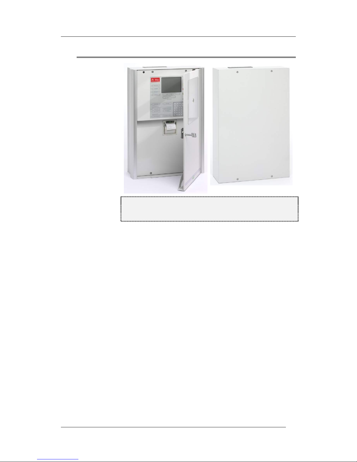
4 Control Unit
Figure 1. Left: The EBL512 G3 Control Unit 5000, with printer.
The look might vary according to configuration, country, etc.
Right: The EBL512 G3 Control Unit 5001.
Depending on country, convention, configuration, etc. the look,
language and functions might vary. Figure 1 shows an EBL512 G3
type 5000 with a front with texts in English. Fronts with texts in other
languages are available. EBL512 G3 is housed in a grey metal
cabinet. The door has a Plexiglas ahead of the front and display, see
Figure 1. A key is required to open the door to get full access to the
push buttons on the front, i.e. the Fire Brigade Panel (FBP) and the
Control Panel (CP).
EBL512 G3 type 5001 has no front, display and printer and is housed
in a grey metal cabinet without a door.
Panasonic Electric Works Nordic AB
MEW01349 Rev: - Operating Instructions Fire alarm system EBL512 G3, V1.1.x
16
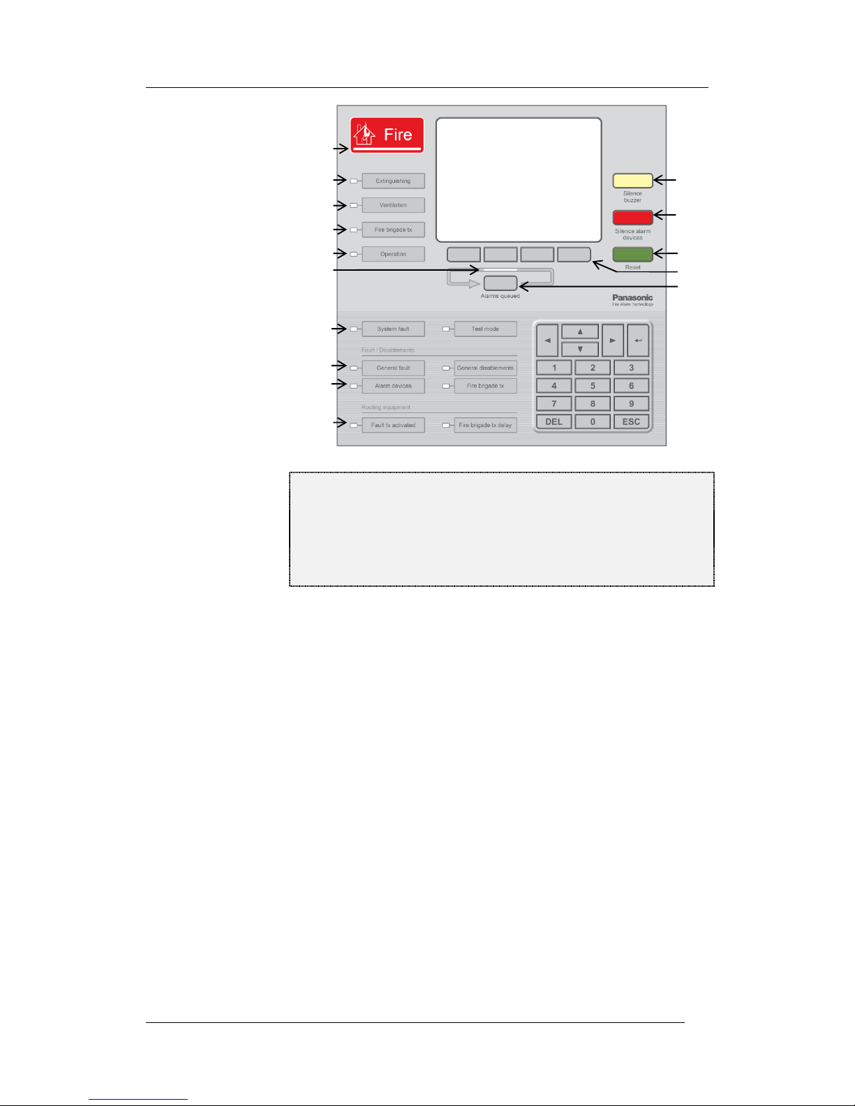
Figure 2. The EBL512 G3 front with display; The Fire Brigade
Panel (FBP) is the upper part and the Control Panel (CP) is the
lower part. The look might vary according depending on
language, country, etc. (A front with texts in English is shown in
the figure). See also chapter "LED indicators and push
buttons", page 17.
The fire brigade personnel use the FBP to see which alarm point /
zone(s) having activated fire alarm and to take required operational
control of the system. In the graphical display, the information in the
upper part is depending on how many alarm points / zones having
generated fire alarm. In the middle part a user definable text message
(alarm text) is shown for each alarm point / zone in alarm - if
programmed.
The CP is to "communicate" with the system, i.e. for commissioning,
monthly tests, maintenance, etc. Access codes for different access
levels are required. A keypad is used to get access to the system (a
menu tree with main and sub menus) and for different manoeuvres.
The CP has several LEDs for system status.
In the Australian front only, below the "P3" button, there is also a
"Disable" push button, with which you can "Disable zones in alarm".
L3
L6
L2
L1
L4
L5
L7, L8
L9, L10
L11, L12
L13, L14
P1
P2
P3
P8
P4 – P7
Panasonic Electric Works Nordic AB
MEW01349 Rev: - Operating Instructions Fire alarm system EBL512 G3, V1.1.x
17
5 LED indicators and push buttons
LEDs and push buttons can vary according to type and configuration
(convention / country / language).
See also Figure 2, page 16.
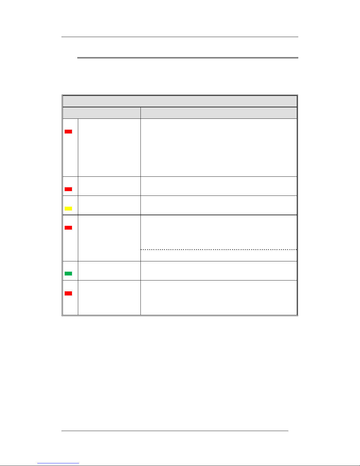
LED indicators on the Fire Brigade Panel (FBP)
LED indicator
Indicating
L1
Fire (5 red)
Fire alarms (see below)
Co-incidence alarm
Pre-warning
Quiet alarm (normally Australia only)
Alarm Acknowledgement Facility (AAF) alarm (Australia
only)
See also chapter "Alarm types", page 38.
L2
Extinguishing (red)
Output(s) for extinguishing equipment activated. (Or a
programmable input type "Extinguishing" is activated.)
L3
Ventilation (yellow)
Output(s) for fire/smoke ventilation equipment activated. (Or
a programmable input type "Ventilation" is activated.)
L4
Fire brigade tx (red)
Output "Fire alarm" for fire brigade tx (routing equipment)
and/or corresponding programmable output(s) of type
"Routing equipment") is/are activated. (Or a programmable
input type "Activated routing equipment" is activated.)
Test of routing equipment in progress (see menu H1).
L5
Operation (green)
The c.i.e. is powered via the rectifier and/or the battery.
L6
Alarms queued (2 red)
More than one unit / zone have activated fire alarm. Use
push button "Alarms queued" (P8) to scroll amongst the
alarm points or soft key "Next zone" (P5) to scroll amongst
the zones.
NOTE! Fire alarms are:
Fire alarm (incl. test mode alarm)
Heavy smoke/heat alarm
Alert Annunciation (AA) alarm
Key cabinet alarm
Acknowledged alarm (New Zealand only)
Isolated alarm (New Zealand only)
Panasonic Electric Works Nordic AB
MEW01349 Rev: - Operating Instructions Fire alarm system EBL512 G3, V1.1.x
18
Push buttons on the Fire Brigade Panel (FBP)
Push button
Operation/function
P1
Silence buzzer (yellow)
Used to silence the buzzer in the c.i.e.
P2
Silence Alarm devices
(red)
Used to silence alarm devices / sounders (i.e. outputs of type
"Alarm devices" will be de-activated). Silenced Alarm
devices is indicated to the right in the display's soft key area
(a symbol near this button), see page 21.
P3
Reset (green)
Used to reset:
Fire alarms (see below)
Co-incidence alarms (if not automatically reset)
For more information see "Alarm reset", page 49.
NOTE! P3 has to be pressed for > 0.5 sec.
Disable (yellow)
NOTE! This button exists in the Australian front only!
Disable zones in alarm.
P4 – P7
Soft keys (grey)
The operation/function is shown above the key in the display
(i.e. the soft key area). The function of a soft key may vary
depending on the situation. If nothing is shown above the
key in the display, the key has no function for the moment.2
P8
Alarms queued (grey)
Used when LEDs "Alarms queued" (L6) are lit, to
scroll/browse through the queued alarm points. Function, see
chapter "Fire alarm", page 39, under LEDs "Alarms
queued".
NOTE! Fire alarms are:
Fire alarm
Heavy smoke/heat alarm
Alert Annunciation (AA) alarm
Key cabinet alarm
Acknowledged alarm (New Zealand only)
Isolated alarm (New Zealand only)
2
The soft key "P7" has the function Evacuate in the following conventions:
Belgian, Brittish Standard, Hungarian, Spanish and Ukrainian. In all other
conventions it has the function Alert Annunciation Acknowledge.
Panasonic Electric Works Nordic AB
MEW01349 Rev: - Operating Instructions Fire alarm system EBL512 G3, V1.1.x
19
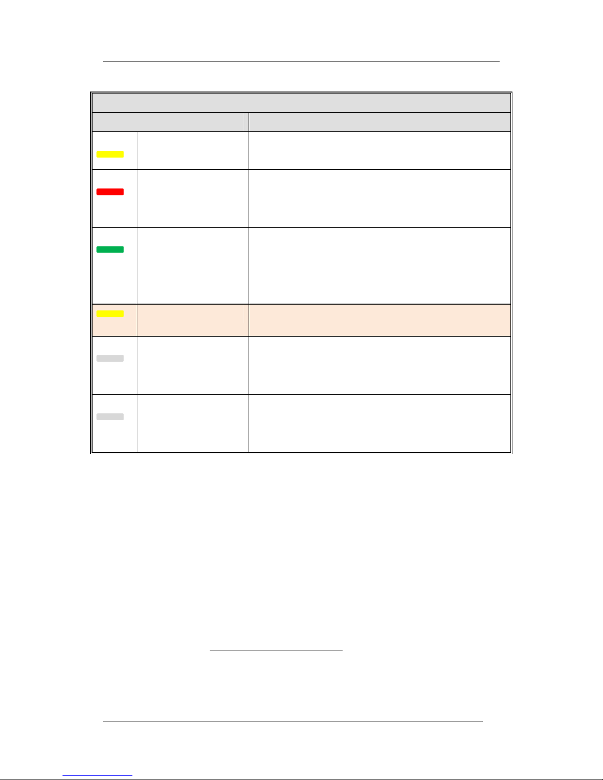
LED indicators on the Control Panel (CP)
LED indicator
Indicating
L7
System fault (yellow)
EBL512 G3 is not running because of S/W, CPU or
memory fault.
L8
Test mode (yellow)
One or more zones are in "test mode", see page 87 and
127.
Fault / Disablements
L9
General fault (yellow)
Fault(s) in the system, i.e. not acknowledged fault(s)
and/or not corrected fault(s). See also page 126.
L10
General disablements
(yellow)
Disablement(s) in the system. Also valid for "Single
with automatic disablement", see page 50.
L11
Alarm devices (yellow)
Steady / cont.: Output(s) type "Alarm device" are
disabled.
Blinking: One or more supervised outputs type
"Alarm device" have generated fault(s).
This is also valid when the c.i.e. has no "contact" with
a unit with such an output, e.g. 3377, 3379, 3364, etc.
L12
Fire brigade tx (yellow)
Steady / cont.: Output(s) for "Routing equipment"
disabled via menu (H2/B3 or B9) or via open door.
Blinking: Routing equipment power supply output3 or
one or more supervised outputs (of type "Routing
equipment" have generated fault(s). This is also valid
when the c.i.e. has no "contact" with a unit with such
an output, e.g. 3361, etc.
Routing equipment
L13
Fault tx activated (yellow)
One or more not acknowledged faults. 4 Output "Fault
condition" for fault tx (routing equipment) is activated.
Test of routing equipment in progress (see menu H1).
Sensitive fault detection mode (see menu H5/A2) is on.
L14
Fire brigade tx delay
(yellow)
The Alert Annunciation function is enabled, i.e. time
channel controlling this function is "on". The AA
function is described in the EBL512 G3 Planning
Instructions, chapter "Alert Annunciation". LED
"L14" will be "on" if the AA function is enabled for at
least one alarm point / zone. Normally is only one
time channel used for this function but two or more
channels can be used. The AA function can, as an
alternative, be continuously "on".
3
Main board 5010 term. block "J3:3-4", fuse F8 (T500mA L 250 V – TR5).
4
See also chapter "Fault acknowledge", page 70.

Panasonic Electric Works Nordic AB
MEW01349 Rev: - Operating Instructions Fire alarm system EBL512 G3, V1.1.x
20
Push buttons / Keypad on the Control Panel (CP)
Key/push button
Operation/function
↵ (Enter)
Used to log on, i.e. to get access to the menu tree (via an access
code) and to accept a menu and accept input of data.
◄ ► ▲ ▼
Left / right keys are used to move the cursor in a menu.
Up / down keys are used to scroll between the menus.
1 – 9 and 0
Numeric keys for the figures 0-9.
DEL
Used to clear /delete just written data.
ESC
Used to stop input of data, leave a menu ("one step up").
Panasonic Electric Works Nordic AB
MEW01349 Rev: - Operating Instructions Fire alarm system EBL512 G3, V1.1.x
21
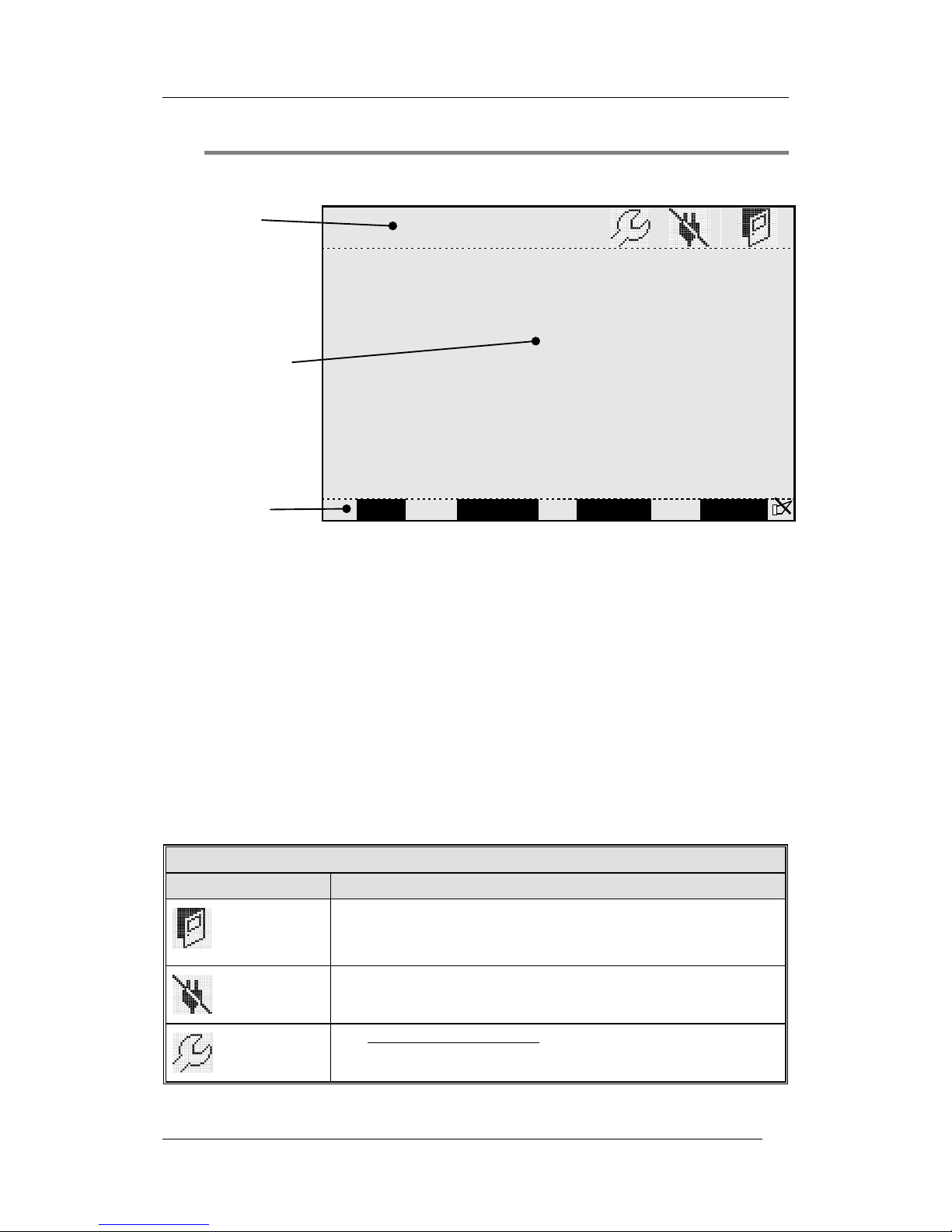
6 The display (LCD)
6.1 Areas in the display
Symbol area
Information area
Soft key area
Menu
Next zone
Re-enable
Evacuate
The display is divided in three areas:
The symbol area: Some events are indicated with symbols, see 6.2
below.
The information area: General area for all kind of information
and the menu system.
The soft key area: The function of a soft key is shown here and
may vary depending on the situation, convention and language.
If no text is shown, the soft key has no function. When
"Evacuate" is not used this soft key may be used for "Alert
Annunciation acknowledge". In the New Zealand convention it
is used for "Acknowledge alarm". ).
Silenced Alarm devices is indicated to the right in this area.
6.2 The symbol area
The symbol area is at the top of the display, see 6.1 above.
The symbol area
Symbol
Indicating
Door open.
Any c.i.e. door in the system is opened. See also page 35.
Also valid for ext. FBPs.
Loss of mains.
Any c.i.e. or ext. power supply in the system is out of 230 V AC.
The week average sensor value is over the service level for one or
more analog smoke detectors in the system. See also page 111.
Note that the symbol area may be suppressed see 6.3.

Panasonic Electric Works Nordic AB
MEW01349 Rev: - Operating Instructions Fire alarm system EBL512 G3, V1.1.x
22
6.3 The information area priority order
When the control unit / system is in normal operation (quiescent
state), i.e. no fire alarms, no faults, no disablements, no service
signals, no zones in test mode, no activated interlocking in / outputs,
and/or Alert Annunciation function not enabled, only the LED
"Operation" (L5) should be lit and some system information is
shown in the control unit display. However, the system information
has the lowest priority and more important information suppresses less
important. In some cases also valid for the symbol area.
The priority order is:
Priority
Event
Symbol area
is visible
1
Fire alarms (see below)
No 2 Quiet alarm
No 3 Co-incidence alarm
No 4 Pre-warning
No 5 AAF alarm5
Yes 6 Evacuate information6
Yes
7
New Zealand convention only:
Routing equipment left isolated
Yes
8
Fault (not acknowledged)
Yes 9 Disablement
Yes
10
Zones in Test mode
Yes
11
Interlocking input / output active
Yes
12
System information
Yes
NOTE! Fire alarms are:
Fire alarm
Heavy smoke/heat alarm
Alert Annunciation (AA) alarm
Key cabinet alarm
Acknowledged alarm (New Zealand only)
Isolated alarm (New Zealand only)
The different type of events and the menu system are described in
other parts of this document. Regarding "System information", see
6.4.
5
The AAF function is used in conjunction with an AAF Control, which is
available on the Australian market only.
6
Only valid for Belgian, British Standard, Hungarian, Spanish and
Ukrainian conventions.

Panasonic Electric Works Nordic AB
MEW01349 Rev: - Operating Instructions Fire alarm system EBL512 G3, V1.1.x
23
6.4 System information in the LCD
EBL512 G3, control unit number, date and time are displayed. The
exact look is convention / language dependent.
One example:
EBL512 G3
Control Unit: XX
yyyy-mm-dd hh:mm
yyyy-mm-dd = (Date) Year-Month-Day
Control Unit; XX = 00-29
hh:mm = (Time) hour:minute
NOTE!
When the Russian, Ukraine, Australian or the New Zealand language
is selected the date is shown as follows: dd-mm-yyyy.
6.4.1 User definable system information
User definable system / installation information (created and
downloaded via WinG3) can be displayed in the middle of the display.
Two rows à 40 characters are available. This information is shown in
all control units in the system.
One example:
EBL512 G3
Control Unit: 00
Panasonic Electric Works
Nordic AB
2011-02-02 10:58

Panasonic Electric Works Nordic AB
MEW01349 Rev: - Operating Instructions Fire alarm system EBL512 G3, V1.1.x
24
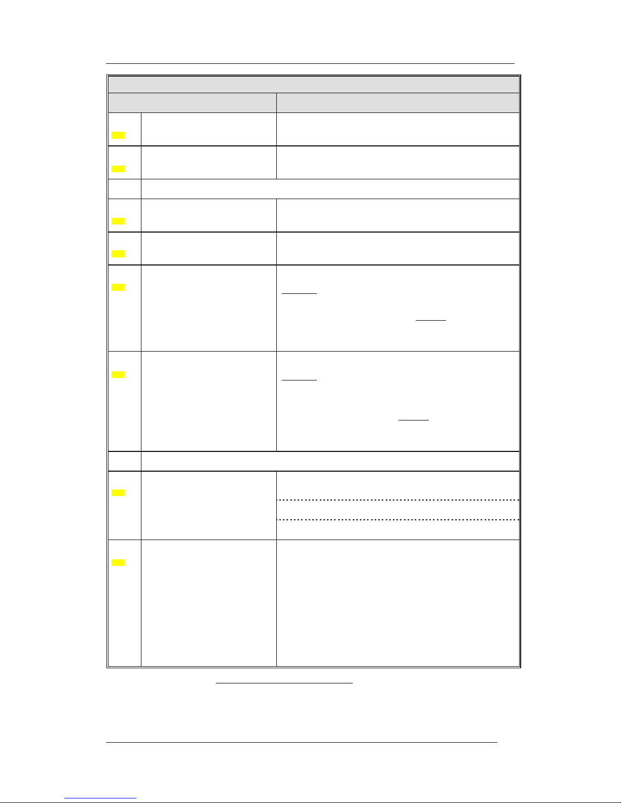
7 Access levels
EBL512 G3 has different access levels (1-4) for different kind of
users. Access levels 2 and 3 are divided in sub levels (A-B).
Access
level
Access code
(password)
Required action
Users
Action
1
N/A
None
(Door closed).7
Anybody.
Scroll / browse
through the queued
alarms.
2A
N/A
Fire brigade key.
Fire brigade
personnel.
Fire alarm handling.
2B
****
Fire brigade key +
access code for level
2B (or 3A).
Building
occupier /
installation
owner.8
Installation handling
(daily duties), e.g.
monthly tests, disablements, etc.
3A
****
Fire brigade key +
access code for level
3A.
Service /
maintenance
personnel.
Service,
maintenance,
commissioning, etc.
3B
********
PC (WinG3)
connected + PC
access code for level
3B.
Service /
maintenance /
commissioning
engineer.
Service,
maintenance,
commissioning, etc.
via WinG3.
4
********
PC (WinG3)
connected + PC
access code for level
3B and level 4.
Manufacturer.
Changing factory
settings.
The access codes can be changed. To change a code you have to use
the valid code or use a code for a higher access level.
Retailers are informed regarding the default access code respectively.
7
The c.i.e. door is closed but the Plexiglas in the door is provided with a
hole for access to the "Alarms queued" button (P8), see Figure 1, page 14.
8
Normally a person on site, trained in order to perform monthly tests, dis-
ablements, etc.
Panasonic Electric Works Nordic AB
MEW01349 Rev: - Operating Instructions Fire alarm system EBL512 G3, V1.1.x
25
7.1 Access level 1
With the door closed7, anybody has access to the push button "Alarms
queued" (P8) to scroll / browse through the queued alarms.
7.2 Access level 2A
After the door has been opened ("Door open" symbol in the
symbol field), the user / fire brigade personnel have access to the
push buttons / keypad to do the following:
Push
button
Operation/function
P1
Silence the buzzer in the c.i.e.
P2
Silence all alarm devices (sounders).
P3
Reset fire alarms. (see below)
NOTE! Fire alarms are:
Fire alarm (incl. heavy smoke/heat alarm)
Alert Annunciation (AA) alarm
Key cabinet alarm
Co-incidence alarm (if not reset automatically)
Acknowledged alarm (New Zealand only)
Isolated alarm (New Zealand only)

Panasonic Electric Works Nordic AB
MEW01349 Rev: - Operating Instructions Fire alarm system EBL512 G3, V1.1.x
26
7.3 Access level 2B
After the door has been opened ("Door open" symbol in the
symbol field), the building occupier has access to level 2A and after
access code for level 2B (or 3A), access to the following menus:
H1 Perform monthly test
H2 Disable or re-enable
B1 Disable zone
B2 Disable zone / address
B3 Disable output
B4 Re-enable zone
B5 Re-enable zone / address
B6 Re-enable output
B7 Disable / re-enable output type
B8 Disable / re-enable alarm devices
B9 Disable / re-enable routing equipment
B10 De-activate alert annunciation function
H3 Set calendar and clock
H4 Present system status
U1 Disablement
U2 Disablement by time channel
U3 Open doors
U4 Sensor values
U5 Sensors activating SERVICE signal
U6 Event log
U7 Information
H6 FAULT acknowledge
H7 Perform zone test (Test mode)
H9 Interlocking outputs and inputs
C1 Activated interlocking outputs/inputs
C2 Activate interlocking output
C3 Reset interlocking output
C4 Disable interlocking output
C5 Re-enable interlocking output
H10 Change access code for daily duties

Panasonic Electric Works Nordic AB
MEW01349 Rev: - Operating Instructions Fire alarm system EBL512 G3, V1.1.x
27
7.4 Access level 3A
After the door has been opened ("Door open" symbol in the
symbol field), the service / maintenance personnel have access to
level 2A and after access code for level 3A, access to the following
menus:
Same menus as in access level 2B plus the following:
H5 Service
A1 Calibration of supervised outputs
A2 Sensitive fault detection mode
A3 Service mode for COM-loop
A4 Display current consumption in CU
A5 Display current consumption on COM-loop
A6 Display statistics for communication
A7 Activate address setting mode for DU
H8 Maintenance
S1 Disconnect loop / zone line input
S2 Re-connect loop / zone line input
S3 Acknowledge SERVICE signal
S4 Clear weekly average
S5 Test of alarm devices
S6 Safe shut down of control unit
S7 Activate address in alarm mode
S8 Synchronize the control units
S9 Change code for service / maintenance
S10 Change code for PC-communication
7.5 Access level 3B
Used by Service / maintenance / commissioning engineers when a PC
(i.e. WinG3) is to be connected to EBL512 G3 for backup (upload),
download of site specific data and/or download of software.
7.6 Access level 4
Used by manufacturer or by personnel authorised by the manufacturer
when a PC is to be connected to the control unit, i.e. when WinG3 is
to be used for re-initialisation of the alarm counter, change software
configurations, on-line status checking, etc.
Panasonic Electric Works Nordic AB
MEW01349 Rev: - Operating Instructions Fire alarm system EBL512 G3, V1.1.x
28
8 "Silence Alarm devices"
In the control unit front (the FBP part) there is a push button "Silence
alarm devices" (P2).
When the alarm devices are activated (sounding)9 and the push button
"Silence alarm devices" is pressed, the following will happen:
The activated outputs programmed for sounders (i.e. type
"Alarm devices", will be turned OFF (de-activated)10
If the push button "Silence alarm devices" is pressed again, the
sounders will automatically sound again.
In case of a new alarm the sounders will automatically sound again.
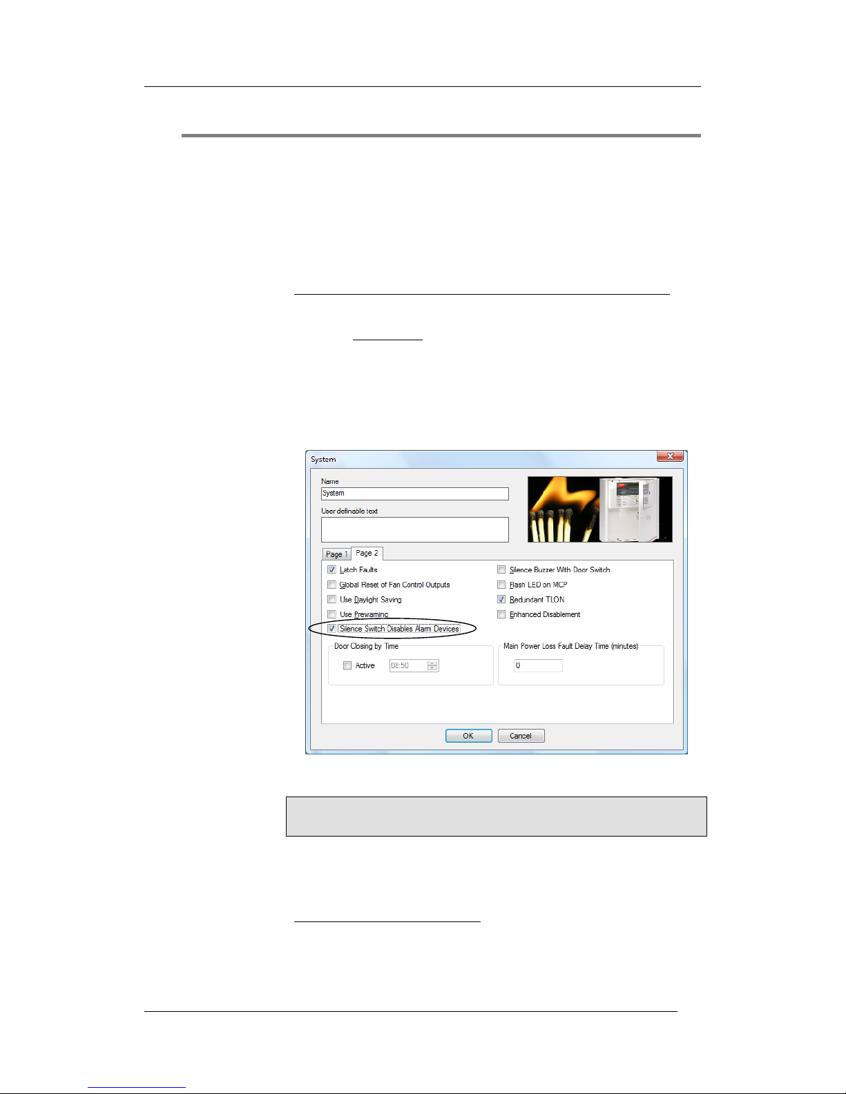
In WinG3, the function “Silence Switch Disables Alarm Devices” can
be selected. In this case the button "Silence alarm devices" (P2) will
have the same function as the menu “Disable / re-enable alarm devices
(H2/B8)”. See also chapter "Disable / Re-enable alarm devices", page
31.
8.1 Silence alarm devices (inside switch)
NOTE! The functions in this chapter are valid for the New Zealand
convention only.
The button "Silence alarm devices" (P2) is called the "inside switch"
and has the following function:
The inside switch toggles between two states.
9
E.g. during Fire alarm or Alert Annunciation alarm.
10
Including Addressable siren 3377 and Addressable sounder base 3379.
 Loading...