

Panasonic MEW01091, EBL128 V1.1.x Operating Instructions Manual

Operating Instructions
MEW01091
Revision 3
Fire Alarm System EBL128
V1.1.x
Author: Jan Pettersson
Date of issue: 2008-07-11
Date of rev: 2010-05-28

This page has deliberately been left blank.

Panasonic Electric Works Nordic AB
MEW01091 Rev: 3 EBL128 Operating Instructions V1.1.x
1
Table of contents
1 Introduction________________________________ 6
2 Definitions / Explanations ____________________ 8
2.1 PEWF&STE AB ___________________________________ 8
2.2 Alarm point _______________________________________ 8
2.2.1 Smoke detector ________________________________ 8
2.2.2 Sensor _______________________________________ 8
2.2.3 Analog detector ________________________________ 8
2.2.4 (Analog) Sensor Base (ASB) _____________________ 8
2.2.5 Conventional detector ___________________________ 8
2.2.6 Conventional Detector Base (CDB) ________________ 8
2.2.7 Addressable ___________________________________ 8
2.2.8 Old detector ___________________________________ 9
2.2.9 Conventional zone line __________________________ 9
2.2.10 Addressable zone interface _______________________ 9
2.3 Output unit _______________________________________ 9
2.4 Output / Control output ______________________________ 9
2.5 Short circuit isolator ________________________________ 9
2.6 Display unit _______________________________________ 9
2.7 COM loop ________________________________________ 9
2.8 Control Unit (C.U.) / C.I.E. ___________________________ 9
2.9 Fire Brigade Panel (FBP) ____________________________ 9
2.10 Control panel (CP) ________________________________ 10
2.11 LED ____________________________________________ 10
2.12 External Indicator (LED) ___________________________ 10
2.13 Display / LCD ____________________________________ 10
2.14 Door open / Key switch _____________________________ 10
2.15 SSD / Site Specific Data ____________________________ 10
2.16 S/W / Software / System program _____________________ 10
3 Overview _________________________________ 11
3.1 The EBL128 c.i.e. _________________________________ 11
3.2 S/W versions _____________________________________ 11
3.3 Documents ______________________________________ 11
3.4 Applications _____________________________________ 11
3.5 PC S/W _________________________________________ 11
4 Control & Indicating Equipment _____________ 12
5 LED indicators and push buttons _____________ 14
6 Normal operation __________________________ 20
6.1 The display in EBL128 _____________________________ 20
6.1.1 LCD backlight ________________________________ 20
6.1.2 The LCD information priority order _______________ 20
7 Access levels _______________________________ 22

Panasonic Electric Works Nordic AB
MEW01091 Rev: 3 EBL128 Operating Instructions V1.1.x
2
7.1 Access level 1 ____________________________________ 23
7.2 Access level 2A ___________________________________ 23
7.3 Access level 2B ___________________________________ 24
7.4 Access level 3A ___________________________________ 25
7.5 Access level 3B ___________________________________ 25
7.6 Access level 4 ____________________________________ 26
8 "Silence Alarm devices"_____________________ 27
8.1 Silence alarm devices (inside switch) __________________ 27
8.2 New Zealand FB Silence switch (outside switch) _________ 28
9 Disable / Re-enable alarm devices _____________ 29
10 "Silence buzzer" ___________________________ 30
10.1 Buzzer __________________________________________ 30
11 Disable / Re-enable all control, extinguishing and
ventilation outputs _______________________________ 31
12 Evacuate, LED Test, Alert Annunciation
Acknowledge and Disable _________________________ 32
12.1 Evacuate ________________________________________ 32
12.2 LED Test ________________________________________ 32
12.3 Alert Annunciation Acknowledge _____________________ 32
12.4 Disable _________________________________________ 32
13 German functions / units ____________________ 33
13.1 Push-button "ÜE prüfen" ___________________________ 33
13.2 Button "Brandfall Steuerungen ab" ____________________ 33
13.3 Indication "Brandfall Steuerungen ab" _________________ 34
13.4 Button "Akustische Signale ab" ______________________ 34
13.5 Indication "Akustische Signale ab" ____________________ 34
13.5.1 Indication in button "Akustische Signale ab" ________ 34
13.6 The buzzer in the c.i.e. _____________________________ 34
13.7 Button "ÜE ab" ___________________________________ 34
13.8 Indication "ÜE ab" ________________________________ 35
13.9 Disablements of outputs; Information in the c.i.e. and FAT
display respectively. _____________________________________ 35
14 Door open ________________________________ 36
14.1 LED "Door open" _________________________________ 36
14.2 Outputs for routing equipment (Fire brigade tx and Fault tx) 36
14.3 Silence buzzer ____________________________________ 36
15 Technical address / Presentation number ______ 37
15.1 Technical address for COM loop units _________________ 37
15.2 Presentation number _______________________________ 37
16 Alarm types _______________________________ 38
16.1 Pre-warning ______________________________________ 38
16.2 Fire alarm _______________________________________ 39
16.2.1 Fire alarm menu (X1-X9) _______________________ 42

Panasonic Electric Works Nordic AB
MEW01091 Rev: 3 EBL128 Operating Instructions V1.1.x
3
16.2.2 Alert Annunciation alarm (AA alarm) _____________ 45
16.2.3 Co-incidence alarm (two-unit / -zone dependence) ___ 46
16.3 Heavy smoke alarm / Heavy heat alarm ________________ 46
16.4 Key cabinet alarm _________________________________ 47
16.4.1 Key cabinet opened before a fire alarm_____________ 47
16.4.2 Key cabinet opened in conjunction with a fire alarm __ 48
16.4.3 Key cabinet alarm, Danish (DBI) convention ________ 48
16.5 Quiet alarm ______________________________________ 48
16.6 Alarm Acknowledgement Facility (AAF) _______________ 49
17 Alarm reset _______________________________ 50
17.1 Pre-warning reset _________________________________ 50
17.2 Fire alarm reset ___________________________________ 50
17.2.1 Multiple reset ________________________________ 50
17.2.2 Single encapsulated reset _______________________ 50
17.2.3 Alert Annunciation ____________________________ 51
17.2.4 Co-incidence alarm ____________________________ 51
17.3 Heavy smoke / heat alarm reset ______________________ 52
17.4 Key cabinet alarm reset _____________________________ 52
17.5 Quiet alarm reset __________________________________ 52
17.6 Alarm Acknowledgement Facility (AAF) reset __________ 52
17.7 Acknowledged alarm ______________________________ 53
17.8 Isolated alarm ____________________________________ 53
18 Fault _____________________________________ 54
18.1 Fault messages ___________________________________ 55
18.2 Fault acknowledge ________________________________ 67
19 Commissioning an EBL128 __________________ 68
20 SSD programming & download ______________ 69
20.1 SSD programming _________________________________ 69
20.2 Auto generating SSD _______________________________ 69
20.3 SSD download ____________________________________ 69
20.4 Download of Alarm texts ___________________________ 70
21 Software (S/W) download ___________________ 71
21.1 Download of S/W in EBL128 (c.i.e.) __________________ 71
21.2 Upgrade of S/W version 1.0.x to version 1.1.x in EBL128
(c.i.e.) 72
21.3 Earlier S/W version download _______________________ 73
21.4 S/W download in Display Units ______________________ 73
22 Restart ___________________________________ 74
22.1 Boot menu _______________________________________ 76
23 Access ____________________________________ 78
24 Perform monthly test (H1) ___________________ 79
25 Disable or re-enable (H2) ____________________ 81
25.1 Disable zone (H2/B1) ______________________________ 81

Panasonic Electric Works Nordic AB
MEW01091 Rev: 3 EBL128 Operating Instructions V1.1.x
4
25.2 Disable zone / address (H2/B2) _______________________ 83
25.3 Disable output (H2/B3) _____________________________ 84
25.4 Disable all control, extinguishing, ventilation and alarm device
outputs (H2/B4) _________________________________________ 85
25.5 Re-enable zone (H2/B5) ____________________________ 86
25.6 Re-enable zone / address (H2/B6) _____________________ 87
25.7 Re-enable output (H2/B7) ___________________________ 88
25.8 Re-enable all control, extinguishing, ventilation or alarm
device outputs (H2/B8) ___________________________________ 90
25.9 Disable or re-enable outputs for routing equipment (H2/B9) 91
25.10 De-activate alert annunciation function (H2/B10) ______ 92
26 Set calendar and clock (H3) __________________ 93
26.1 Daylight saving time _______________________________ 94
27 Present system status on display (H4) __________ 95
27.1 Disablement (H4/U1) ______________________________ 95
27.2 Disablement by time channel (H4/U2) _________________ 96
27.3 Sensor values (H4/U3) _____________________________ 97
27.3.1 Reset of a week average sensor value ______________ 99
27.4 Sensors activating SERVICE signal (H4/U4) ___________ 100
27.5 Event log (H4/U5) ________________________________ 101
27.6 Show configuration and alarm counter (H4/U6) _________ 102
28 Service (H5) ______________________________ 103
28.1 Access code for service and maintenance ______________ 104
Disconnect / Re-connect COM loop (H5/A1) _________________ 105
28.2 Disconnect / Re-connect zone line input (H5/A2) _______ 106
28.3 Calibration of supervised outputs (H5/A3) _____________ 107
28.4 Sensitive fault detection mode (H5/A4) _______________ 108
28.5 Service mode for COM-loop (H5/A5) ________________ 109
28.6 Show information about Site Specific Data (H5/A6) _____ 111
28.7 Display current consumption on COM loop (H5/A7) _____ 112
28.8 Display statistics for COM loop (H5/A8) ______________ 113
28.9 Activate address setting mode for DU (H5/A9) _________ 114
29 Acknowledge FAULTS (H6) ________________ 115
30 Perform ZONE TEST (test mode) (H7) _______ 116
31 Maintenance (H8) _________________________ 118
31.1 Access code for service and maintenance ______________ 118
31.2 Acknowledge SERVICE signal (H8/S1) _______________ 119
31.3 Restore weekly average to default (H8/S2) _____________ 120
31.4 Test of alarm devices (H8/S3) _______________________ 121
31.5 Safe shut down of control unit (H8/S4) _______________ 122
31.6 Activate address in alarm mode (H8/S5) ______________ 123
31.7 Change access code for service and maintenance (H8/S6) _ 125
31.8 Change access code for PC-communication (H8/S7) _____ 126
32 Interlocking outputs and inputs (H9) _________ 127

Panasonic Electric Works Nordic AB
MEW01091 Rev: 3 EBL128 Operating Instructions V1.1.x
5
32.1 Activated interlocking outputs/inputs (H9/C1) __________ 127
32.2 Activate interlocking output (H9/C2) _________________ 128
32.3 Reset interlocking output (H9/C3) ___________________ 129
32.4 Disable interlocking output (H9/C4) __________________ 130
32.5 Re-enable interlocking output (H9/C5) ________________ 131
33 Change access code for daily duties (H10) _____ 132
34 Annual control ___________________________ 133
35 Battery maintenance _______________________ 134
36 How to avoid unnecessary (nuisance) fire alarms 135
37 Revision history ___________________________ 137

Panasonic Electric Works Nordic AB
MEW01091 Rev: 3 EBL128 Operating Instructions V1.1.x
6
1 Introduction
EBL128 Operating Instructions is a document1 with information of
special interest for the end user and the fire brigade personnel, as
well as service / commissioning engineers.
It should be read in conjunction with the EBL128 Planning
Instructions, since most of the information in one of the documents is
not found in the other document and vice versa.
It should also be read in conjunction with the EBL128 drawings2,
according to the valid Table of drawings.
A Product Leaflet is also available at:
http://www.panasonic-fire-security.com/pewfste/en/html (Data sheets)
Due to continual development and improvement, different S/W
versions are to be found. This document is valid for S/W version
1.1.x. On the date of the document is x=2.
NOTE! Regarding upgrade from S/W version 1.0.x to version 1.1.x
see chapter "Software (S/W) download", page 71.
EBL128 is produced for many countries, accordingly the look, the
texts, the functions, etc. might vary.
Products
Consists of one or more parts (H/W) according to a Product Parts
List. A product has:
a type number (e.g. 4550)
an article number, often = the type no. but sometimes is a
country code added (e.g. 4550SE)
a product name (e.g. EBL128 Control & Indicating
Equipment, 128 addresses)
H/W
A H/W (e.g. a printed circuit board) has:
a type number (e.g. 1556)
an article number, often = the type no. but sometimes is a
country code added (e.g. 1556SE)
a product name (e.g. Main Board 128 addr.)
a p.c.b. number (e.g. 9261-3A) and can also have a configuration
(e.g. CFG: 1) and a revision (e.g. REV: 2)
sometimes a S/W
S/W
A S/W has:
1
File name: K:\PRO\FIRE\128\Doc\V1.1.x\MEW01091 (Rev 3).doc
2
Dimensions & overviews, connection diagrams, etc.

Panasonic Electric Works Nordic AB
MEW01091 Rev: 3 EBL128 Operating Instructions V1.1.x
7
a version number (e.g. V1.11 or V1.1.0)
sometimes additional information, such as Convention (different
functions / facilities), Language, etc.
PC S/W
A PC S/W is a program used for programming, commissioning, etc. It
has a version number.

Panasonic Electric Works Nordic AB
MEW01091 Rev: 3 EBL128 Operating Instructions V1.1.x
8
2 Definitions / Explanations
Definitions / explanations / abbreviations / etc. frequently used or not
explained elsewhere in the document.
2.1 PEWN AB
Panasonic Electric Works Nordic AB
2.2 Alarm point
Unit, which can generate a fire alarm in EBL128, i.e. a sensor, a
conventional detector, a manual call point, etc.
2.2.1 Smoke detector
Two types of analog and conventional smoke detectors are available:
photo electric (optical) and ionization.
2.2.2 Sensor
Sensor = Analog detector
2.2.3 Analog detector
Contains an A/D-converter. EBL128 pick up the digital values
("sensor values") for each detector individually. All evaluations and
"decisions" are then made in EBL128. Analog detectors are
addressable – an address setting tool is used. An analog detector has
to be plugged in an ASB.
2.2.4 (Analog) Sensor Base (ASB)
A sensor is plugged in an ASB, which is connected to a COM loop
(see below).
2.2.5 Conventional detector
Detector with two states, normal or fire alarm. The detector contains a
closing contact and a series alarm resistor. Some types are plugged in
a CDB (see below) but some types are water proof and are not
plugged in any base.
(Conventional detectors are normally plugged in a CDB (see below)
and connected to a conventional zone line with end-of-line device.)
2.2.6 Conventional Detector Base (CDB)
A conventional detector is plugged in a CDB and connected to a
conventional zone line input.
2.2.7 Addressable
A unit with a built-in address device (e.g. a manual call point). Each
unit is individually identified, handled and indicated in EBL128
(The unit can consequently be an I/O unit, to which one or more
conventional "alarm points" can be connected on the zone line.).

Panasonic Electric Works Nordic AB
MEW01091 Rev: 3 EBL128 Operating Instructions V1.1.x
9
2.2.8 Old detector
Conventional detector with a closing contact (short circuit; no alarm
resistor), or detector with two breaking contacts.
2.2.9 Conventional zone line
Zone line input on an I/O unit, intended for one or more conventional
alarm points. End-of-line dive in the last alarm point.
2.2.10 Addressable zone interface
Unit with a zone line input, intended for one or more conventional
alarm points. End-of-line device in the last alarm point.
2.3 Output unit
Addressable unit with programmable control outputs (e.g. an I/O unit).
To be connected to a COM loop (see below).
2.4 Output / Control output
Defined or programmable function. Relay or (supervised / monitored)
voltage output, in EBL128 or an output unit.
2.5 Short circuit isolator
Addressable unit for automatic disconnection of a part of a COM loop
(see below) in case of a short circuit on the loop.
2.6 Display unit
Unit for fire alarm presentation (incl. alarm texts, if programmed).
Connected to an RS485 line.
2.7 COM loop
Loop = a cable with two wires, to which all the addressable MFSTech
units can be connected. It starts in EBL128 and it returns back to
EBL128
2.8 Control Unit (C.U.) / C.I.E.
Control Unit = C.U. = Control and Indicating Equipment = A unit,
e.g. EBL128, to which the alarm points are connected. Indicates fire
alarm, fault condition, etc. on the front, i.e. the Fire Brigade & Control
Panel (see below).
2.9 Fire Brigade Panel (FBP)
The Fire Brigade Panel is a part of the EBL128 front, intended for fire
alarm presentation, etc. for the fire brigade personnel. A separate unit;
an external FBP, can also be connected to EBL128
In the ext. FBP a printer can be included.

Panasonic Electric Works Nordic AB
MEW01091 Rev: 3 EBL128 Operating Instructions V1.1.x
10
2.10 Control panel (CP)
The Control Panel is a part of the EBL128 front, intended for the
building occupier, service personnel, etc. to "communicate" with
EBL128
2.11 LED
LED (Light Emitting Diode) = Yellow, green or red optical indicator
("lamp").
2.12 External Indicator (LED)
A unit with an LED. Connected to an ASB, CDB or a detector with a
built-in LED, for external indication. Lit when the built-in LED is lit.
2.13 Display / LCD
LCD (Liquid Crystal Display) = Display for presentation of fire
alarms, fault messages, etc. Normally alphanumeric characters and
backlight.
2.14 Door open / Key switch
A door / key switch, which has to be activated in order to get access to
the push buttons on the front. Indicated by the LED "Door open".
2.15 SSD / Site Specific Data
This data is unique for each installation. All alarm points,
presentation numbers, alarm texts, programmable outputs, etc. are
programmed (configured) in the PC program Win128 and has to be
downloaded in EBL128.
2.16 S/W / Software / System program
The S/W makes the microprocessor in EBL128 work. It is factory
downloaded but a new version can be downloaded on site.

Panasonic Electric Works Nordic AB
MEW01091 Rev: 3 EBL128 Operating Instructions V1.1.x
11
3 Overview
3.1 The EBL128 c.i.e.
EBL128 is a microprocessor controlled intelligent fire alarm Control
and Indicating Equipment (c.i.e.) intended for analog addressable
smoke and heat detectors. Also conventional detectors and manual
call points can be used. Programmable inputs, control outputs and I/O
units are available. Up to 128 addresses can be connected to EBL128.
EBL128 is fully compliant with the European standard EN54 parts 2
and 4 and the front is fully SS3654 compliant.
3.2 S/W versions
Due to continual development and improvement, different S/W
versions can be found. You can update the S/W in EBL128 on site.
3.3 Documents
The following documents are available:
Planning instructions
Drawings
Operating instructions
Information found in one document is normally not to be found in
another document, i.e. the documents complement each other.
Product Leaflet for EBL128 and other units are available as pdf
documents on our web site: http://www.panasonic-fire-security.com
3.4 Applications
EBL128 is intended for small and medium installations. The
intelligent control unit offer the system designer and end user a
technically sophisticated range of facilities and functions.
Programming (via PC S/W Win128) and commissioning is very easy.
3.5 PC S/W
Win128 is used for programming and commissioning, i.e. to:
create / download / upload (backup) the site specific data (SSD)
download new S/W version / settings / conventions /
configurations / EBL128 data / etc.
create / download the alarm texts shown in the display in EBL128
/ ext. FBP and/or AA units.
Win128 shall have the same version number as the EBL128 S/W
version number, e.g. 1.1.x. Only x may be different. Old SSD files
can be used with a newer EBL128 S/W version. Open and save the
old SSD file in the new Win128 version before the download. If a
backup is required, use the same Win128 version as the EBL128
version.
Panasonic Electric Works Nordic AB
MEW01091 Rev: 3 EBL128 Operating Instructions V1.1.x
12
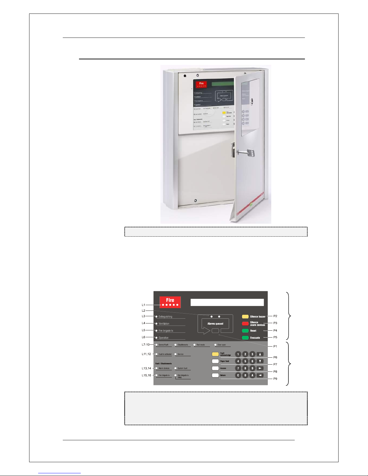
4 Control & Indicating Equipment
Figure 1. The EBL128 Control & Indicating Equipment (4550).
Depending on country, convention, configuration, etc. the look,
language and functions might vary. Figure 1 shows an EBL128 with
an English front. EBL128 is housed in a grey metal cabinet. The door
has a Plexiglas ahead of the front, see Figure 1. A key is required to
open the door to get full access to the push buttons on the front, i.e.
the Fire Brigade Panel (FBP) and the Control Panel (CP).
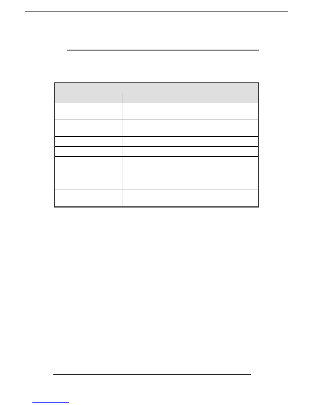
Figure 2. The EBL128 front. The look might vary depending on
the country (language) configuration, etc. (e.g. English texts as
in the figure). See also chapter "LED indicators and push
buttons", page 14.
CP
FBP

Panasonic Electric Works Nordic AB
MEW01091 Rev: 3 EBL128 Operating Instructions V1.1.x
13
The FBP is used by the fire brigade personnel to see which alarm
point / zone having activated the fire alarm(s), silence alarm devices,
reset alarms, etc. In the display (LCD, 2x40 alphanumeric characters),
the information displayed on the first row is depending on how many
alarm points / zones having activated fire alarm, convention and
language.
On the second row is, for the activated alarm point / zone, an alarm
text shown, if programmed. See chapter "Fire alarm", page 39.
Required fire brigade personnel manoeuvres are performed via the
FBP in EBL128 or via an external FBP 1826 / 1828.
Instead of external FBPs 1826 / 1828, the German Fire Brigade
Control Panels (Feuerwehr-Bedienfeld) FBF 2003 and/or German
Fire Brigade Indicator Panels (Feuerwehr-Anzeigetableau) FAT 2002
can be used.
The CP is used by the EBL128 owner, service personnel, etc. to
"communicate" with EBL128, e.g. for monthly tests, disablements
commissioning, maintenance and service. Access codes for different
access levels are required. A keypad is used to get access to the menu
tree, i.e. main and sub menus for data input / output, manoeuvres, etc.
The CP also holds several system status LEDs.
Panasonic Electric Works Nordic AB
MEW01091 Rev: 3 EBL128 Operating Instructions V1.1.x
14
5 LED indicators and push buttons
LEDs and push buttons can vary according to configuration /
convention / country / language.
See also Figure 2, page 12.
LED indicators on the Fire Brigade Panel (FBP)
LED indicator
Indicating
L1
Fire (5 red)
Blinking (0.4/0.4s)
Fire alarm (also pre-warning, heavy smoke/heat alarm & key
cabinet alarm) 3
L2
Alarms queued (2 red)
Blinking (0.4/0.4s)
More than one unit / zone have generated fire alarm.
L3
Extinguishing (red)
Output(s) activated for extinguishing equipment. 4
L4
Ventilation (yellow)
Output(s) activated for fire/smoke ventilation equipment.
L5
Fire brigade tx (red)
Output activated for Fire brigade tx (routing equipment)
and/or corresponding programmable output(s) of type routing
equipment. 4
Test of routing equipment in progress (see menu H1).
L6
Operation (green)
Power on, i.e. EBL128 is power supplied via the rectifier or
the backup battery.
(FBP push buttons on next page)
3
In the New Zealand convention also "Acknowledged alarm" (ACK).
4
L3 and L5 can as an alternative be programmed to indicate when a
programmable input is activated, i.e. input trigger condition "Extinguishing
system released" and "Activated routing equipment" respectively (e.g. L5 can
be turned on when a programmable input is activated by an activated routing
equipment output). L5 is turned on until all fire alarms are reset.
Panasonic Electric Works Nordic AB
MEW01091 Rev: 3 EBL128 Operating Instructions V1.1.x
15
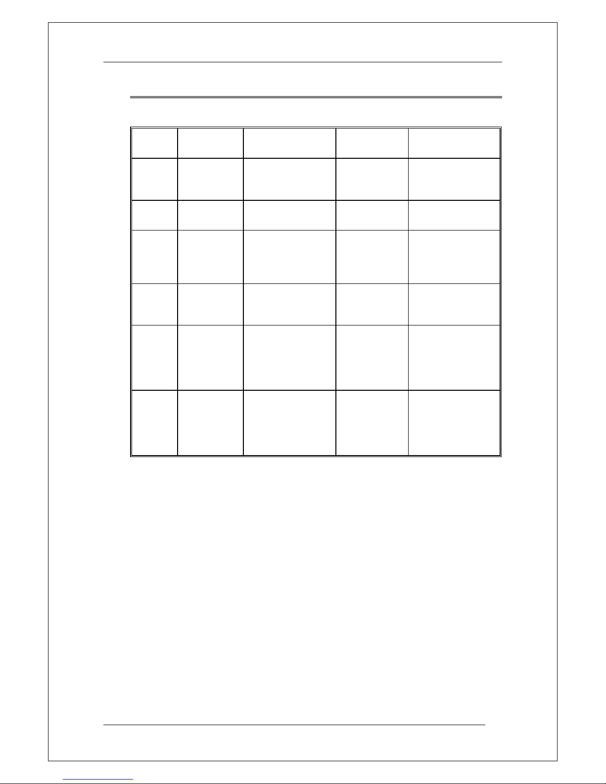
Push buttons on the Fire Brigade Panel (FBP)
Push button
Operation/function
P1
Alarms queued (black)
Used, when LEDs "Alarms queued" (L2) are lit, to
scroll/browse through the queued alarms (zones).
P2
Silence buzzer
(yellow)
Used to silence the buzzer in EBL128
P3
Silence Alarm devices
(red)5
Used to silence the sounders (i.e. to "reset" outputs for alarm
devices).6
P4
Reset (green)
Used to reset the fire alarm(s).7 Has to be pressed for > 0.5
sec.
P5
Evacuate (green) 8
Used to activate all the sounders (i.e. the outputs for alarm
devices).
Alert Annunciation
Acknowledge (green) 9
Used to acknowledge an Alert Annunciation alarm.
Disable (yellow) 10
Used to disables all zones in alarm state.
5
In the New Zealand convention = The "inside switch".
6
Via Win128 can be set if the alarm devices shall be continuous off /
disabled or re-sound for a new alarm.
7
Multiple reset (Default): All fire alarms will be reset simultaneously.
Single encapsulated reset: The fire alarm displayed in the LCD (first row to
the left) will be reset. When more than one fire alarm is activated (LEDs
"Alarms queued" are lit) each fire alarm has to be individually reset. The
encapsulation function is described in chapter "Single encapsulated reset",
page 50.
NOTE (1)! When "Multiple reset" is used, encapsulated reset can be done
by pressing "Reset" (P4) and 0.1 sec. later also press "Alarms queued" (P1)
and hold them pressed for > 0.5 sec. The fire alarm displayed in the LCD
(first row to the left) will be encapsulated or the points in alarm status within
one zone will be encapsulated or the whole zone (conventional) will be
encapsulated.
NOTE (2)! When "Single encapsulated reset" is used, you can make a
"Multiple reset" by pressing "Reset" (P4) and 0.1 sec. later also press "A" (in
the keypad) and hold them pressed for > 0.5 sec.
8
"Evacuate" is only valid in the "Belgian" and "Ukrainian" conventions.
9
"Alert Annunciation Acknowledge" is only valid in the "Czech", Bulgarian
and "Polish" conventions.
10
"Disable" is only valid in the "Australian" and New Zealand conventions.

Panasonic Electric Works Nordic AB
MEW01091 Rev: 3 EBL128 Operating Instructions V1.1.x
16
(CP LED indicators on next page)
Panasonic Electric Works Nordic AB
MEW01091 Rev: 3 EBL128 Operating Instructions V1.1.x
17
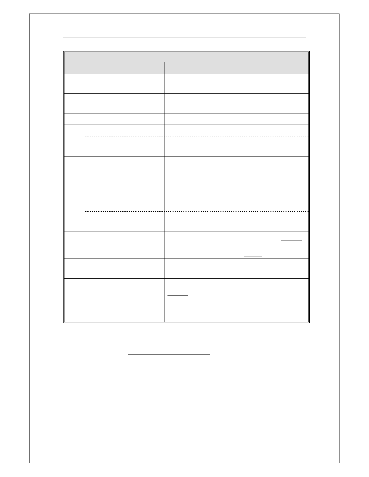
LED indicators on the Control Panel (CP)
LED indicator
Indicating
L7
General fault (yellow)
Fault(s), i.e. not acknowledged fault(s) and/or
acknowledged but not corrected fault(s).
L8
Disablements (yellow)
Something is disabled / disconnected via a menu or
automatically via "Single encapsulated reset" 7.
L9
Test mode (yellow)
One or more zones are in "test mode".
L10
Door open (yellow)
A door is open (in EBL128 or an ext. FBP).11
12
Störung Löschanlage
(yellow)
An input with trigger condition "Extinguishing system
fault" is activated (true).
L11
Fault tx activated (yellow)
Output activated for Fault tx (routing equipment), i.e.
one or more not acknowledged faults.
Test of routing equipment in progress (see menu H1).
L12
Service (yellow)
One or more sensors have reached the service level.
See menu H4/U6.
12
Leitungsstörung
Löschanlage (yellow)
Short-circuit or cut-off (open circuit) on a supervised
input OR a supervised output type "Extinguishing".
L13
Fault / Disablements
Alarm devices (yellow)
One or more outputs (type Alarm device) are disabled.
Blinking: One or more supervised outputs (type
Alarm device) have generated fault(s).13
L14
System fault (yellow)
EBL128 is not running (because of S/W, CPU or
memory fault).14
L15
Fault / Disablements
Fire brigade tx (yellow)
Output for Fire brigade tx (routing equipment) is
disabled via menu (H2/B3) or via an open door.11
Blinking: Routing equipment power supply output15
or one or more supervised outputs (type Routing
equipment) have generated fault(s).16
11
See also chapter "Door open", page 36.
12
L10 and L12 have different functions on the German front.
13
This is also valid when EBL128 has no "contact" with a unit with such an
output, e.g. a 3377, 3378, 3361, etc.
14
The LED is turned on during restart and stays on for restart code other
than 00 and 03 until the fault is acknowledged.
15
Main board terminal block "J1:11-12".
16
This is also valid when EBL128 has no "contact" with a unit with such an
output, e.g. an I/O unit 3361, etc.

Panasonic Electric Works Nordic AB
MEW01091 Rev: 3 EBL128 Operating Instructions V1.1.x
18
L16
Fire brigade tx delay
(yellow)
The Alert Annunciation function is enabled, i.e. the
time channel controlling this function is "on".17
17
The Alert Annunciation function is described in the EBL128 Planning
Instructions, chapter "Alert annunciation". The LED "L16" will be "on" if
the AA function is enabled for at least one alarm point / zone. Normally is
only one time channel used for this function but two or more channels can be
used. The AA function can, as an alternative, be continuously "on".
Panasonic Electric Works Nordic AB
MEW01091 Rev: 3 EBL128 Operating Instructions V1.1.x
19
Push buttons / Keypad on the Control Panel (CP)
Key/push button
Operation/function
P6
Fault acknowledge
(yellow)
Used to acknowledge the faults shown in menu H6. Also used
to acknowledge SERVICE signal, see menu H8/S1. 18
P7
Paper feed (white)
Not used in EBL128.
P8
Access (white)
Used to log on, i.e. to get access to the menu tree (via an access
code) to carry out disablements, etc. In conjunction with a fire
alarm, some information is available and some actions are
possible to perform via the "Fire alarm menu" (X1-X9) without
log on, see chapter "Fire alarm", page 39.
P9
Return (white)
Used to stop input of data, leave a menu ("one step up") and to
log off.
1 – 9 and 0
Numeric keys for the figures 0-9.
C Used to clear /delete just written data.
A Used to accept a menu and accept input of data.
Left / right keys are used to move the cursor in a menu.
Up / down keys are used to scroll between the menus.
18
In the New Zealand convention only, used to acknowledge a Fire alarm,
i.e. the alarm information "ALM" in the LCD is changed to "ACK".
Panasonic Electric Works Nordic AB
MEW01091 Rev: 3 EBL128 Operating Instructions V1.1.x
20
6 Normal operation
When EBL128 is in normal operation and in quiescent state, i.e. no
fire alarms and normally no faults, no disablements, no service signal,
no zones in test mode, no activated interlocking in / outputs and/or no
open doors, only the LED "Operation" (L6) shall be lit.
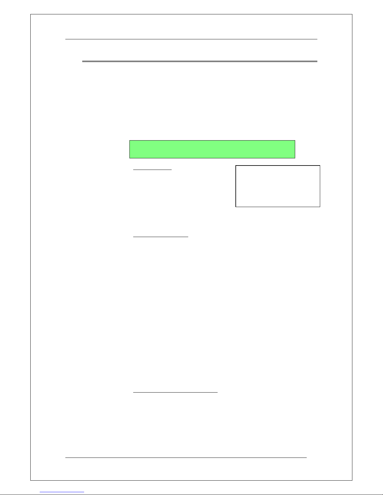
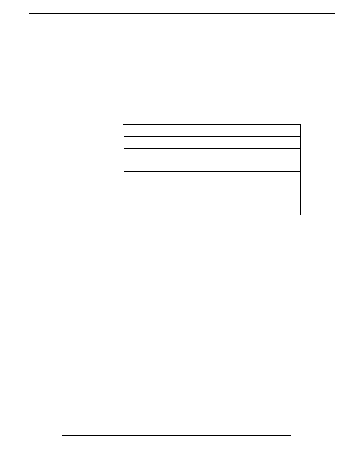
6.1 The display in EBL128
The display (LCD) will in normal operation and in quiescent state
show the following information:
YYYY-MM-DD *** EBL128 *** hh:mm:ss
User programmable information text.
Top (first) row19:
YYYY = Year, e.g. 2005
MM = Month, e.g. 02 (=February)
DD = Day, e.g. 28
hh = hours, e.g. 21
mm = minutes, e.g. 45
ss = seconds, e.g. 45
Bottom (second) row:
The information on the bottom row (40 characters) can be created via
Win128, i.e. it is user definable.
6.1.1 LCD backlight
When the information above is shown in the LCD, the backlight is
OFF.
As soon as any other information (see below) is shown in the LCD,
the backlight is turned ON.
In order to reduce the current consumption, the LCD backlight will be
turned OFF if the c.i.e. is powered only by the second power source,
i.e. the battery.20
6.1.2 The LCD information priority order
The different type of alarms, faults, etc. listed below are described in
other parts of this document.
The LCD information priority order is as follows:
19
The information on the top row (40 characters) is included in the text file
downloaded in EBL128, i.e. the information could be different than the one
showed above.
20
In the Australian and New Zealand conventions, the LCD backlight will
not be turned OFF even if the c.i.e. is powered only by the second power
source.
NOTE! The way the date is
presented can be different
for different languages, e.g.:
DD-MM-YYYY.

Panasonic Electric Works Nordic AB
MEW01091 Rev: 3 EBL128 Operating Instructions V1.1.x
21
1. Fire alarms (Normal fire alarms, Heavy smoke / heat alarms and
Key cabinet alarms) 21
2. Co-incidence alarms
3. Pre-warnings
4. Quiet alarms (Normally used on the Australian market only.)
5. AAF zone alarms (Used in the Australian convention only.22)
6. Evacuate information (only valid in some conventions)
23
7. Faults (not acknowledged)
8. Disablements
9. Zones in Test mode
10. Interlocking in- / outputs active
21
In the New Zealand convention also Acknowledged alarms (ACK) and
Isolated alarms (ISO).
NOTE! A Fire alarm has a "log off function", i.e. if a menu window is open
when a fire alarm is activated, the fire alarm will be presented instead.
Some information is available and some actions are possible to perform via
the "Fire alarm menu" (X1-X9), see chapter "Fire alarm", page 39.
22
Require special equipment available on the Australian market only.
23
Require special equipment available on the New Zealand market only.
In the New Zealand convention:
a. Silence switch left active
b. Alarm routing equipment isolated
c. Fault routing equipment isolated
Panasonic Electric Works Nordic AB
MEW01091 Rev: 3 EBL128 Operating Instructions V1.1.x
22
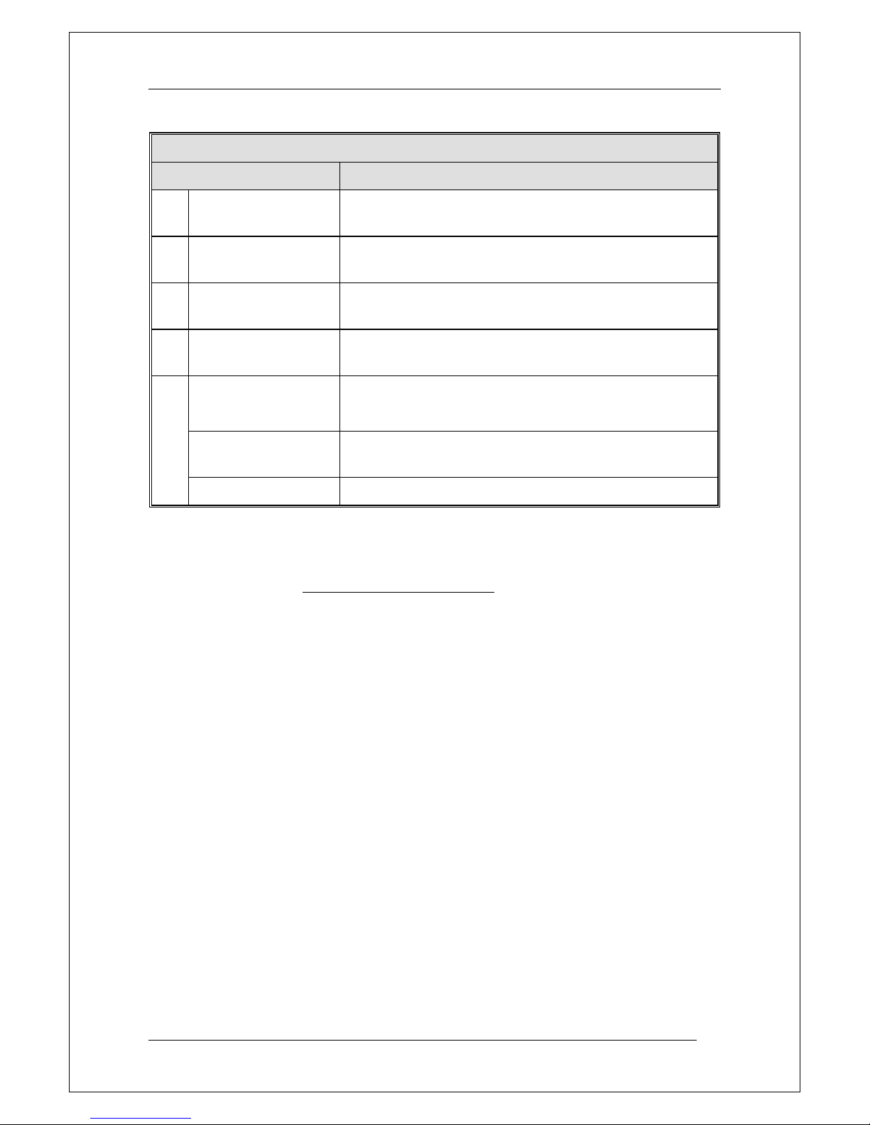
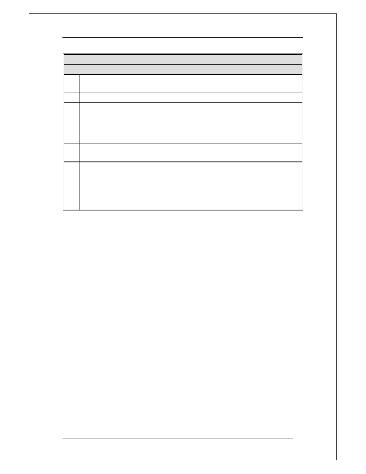
7 Access levels
EBL128 has six access levels for different kind of users.
Access
level
Access code
(password)
Required action
Users
Action
1
N/A
None
(Door closed).
Anybody.
Scroll / browse
through the queued
alarms
2A
N/A
Fire brigade key.
(To open the door.)
Fire brigade
personnel.
Fire alarm handling.
Use menu X1-9.
2B
****
Fire brigade key +
access code for level
2B (or 3A).
Building
occupier.
Installation handling
(daily duties), e.g.
monthly tests, disablements, etc.
3A
****
Fire brigade key +
access code for level
3A.
Service /
maintenance
personnel.
Service,
maintenance.
3B
********
PC (Win128)
connected + PC
access code for level
3B.
Service /
maintenance /
commissioning
engineer.
Service,
maintenance,
commissioning the
system, etc. via
Win128.
4
********
PC (Win128)
connected + PC
access code for level
4.
Service /
maintenance /
commissioning
engineer.
Service,
maintenance,
commissioning the
system, etc. via
Win128.
The access codes can be changed. To change a code you have to
know the valid code or use a code for a higher access level.
Retailers are informed regarding the default access code respectively.
Panasonic Electric Works Nordic AB
MEW01091 Rev: 3 EBL128 Operating Instructions V1.1.x
23
7.1 Access level 1
With the door closed, anybody has access to the push button "Alarms
queued" (P1) – via a circular hole in the plexiglass – to scroll / browse
through the queued alarms.
7.2 Access level 2A
When the door has been opened via the fire brigade key and the door
switch has been activated (LED "Door open" is lit), the fire brigade
personnel have access to the push buttons / keypad to:
(P2) Silence the buzzer in EBL128
(P3) Silence the alarm devices (sounders) in the system.
(P4) Reset fire alarm(s).
(P5) Evacuate (start the sounders).24
(P7) Paper feed (not used in EBL128).
(P8) Access, in conjunction with a fire alarm: The fire brigade
personnel can use "P8" (without any access code) to get access to
the menu X1-X9, i.e. to scroll through all the fire alarms (see all
point alarms), etc.
From access level 2A, the user can logon to access level 2B and 3A
respectively. See the following chapters.
24
Only valid for the "Belgian" and "Ukrainian" conventions. See chapter
"LED indicators and push buttons", page 14, for explanation of use in other
conventions.
Panasonic Electric Works Nordic AB
MEW01091 Rev: 3 EBL128 Operating Instructions V1.1.x
24
7.3 Access level 2B
When the door has been opened via the fire brigade key and the door
switch has been activated (LED "Door open" is lit), the building
occupier has access like in access level 2A and after access code for
level 2B (or 3A) the following menus:
H1 Perform monthly test.
H2 Disable or re-enable.
B1 Disable zone
B2 Disable zone / address
B3 Disable output
B4 Disable all control, ventilation, exting or alarm devices outputs
B5 Re-enable zone
B6 Re-enable zone / address
B7 Re-enable output
B8 Re-enable all control, ventil, exting or alarm devices outputs
B9 Disable / Re-enable outputs for routing equipment
B10 De-activate alert annunciation function
H3 Set calendar and clock.
H4 Present system status on display.
U1 Disablement
U2 Disablement by time channel.
U3 Show values.
U4 Sensors activating SERVICE signal
U5 Show event log
U6 Show configuration and alarm counter
H6 Acknowledge FAULTS.
H7 Perform ZONE TEST (Test mode).
H9 Interlocking outputs and inputs
C1 Activated interlocking outputs/inputs
C2 Activate interlocking output
C3 Reset interlocking output
C4 Disable interlocking output
C5 Re-enable interlocking output
H10 Change access code for daily duties (access level 2B).
Panasonic Electric Works Nordic AB
MEW01091 Rev: 3 EBL128 Operating Instructions V1.1.x
25
7.4 Access level 3A
When the door has been opened via the fire brigade key and the door
switch has been activated (LED "Door open" is lit), the service /
maintenance personnel have access like in access level 2A and 2B
and after access code for level 3A25 the following menus:
H5 Service
A1 Disconnect / Re-connect COM loop
A2 Disconnect/Re-connect zone line input
A3 Calibration of supervised outputs
A4 Sensitive fault detection mode
A5 Service mode for COM-loop
A6 Show information about site specific data
A7 Display current consumption on COM loop
A8 Display statistics for COM loop
A9 Activate address setting mode for DU
H8 Maintenance
S1 Acknowledge SERVICE signal.
S2 Clear weekly average.
S3 Test alarm devices.
S4 Safe shut down of control unit.
S5 Activate address in alarm mode.
S6 Change access code for service and maintenance (access level
3A).
S7 Change access code for PC-communication.
7.5 Access level 3B
Used by Service / maintenance / commissioning engineers when a PC
(i.e. Win128) is to be connected to EBL128 for backup / download of
site specific data.
Connect the PC and logon to EBL128 from the PC (Win128).
25
If the code for access level 3A has already been used to logon to access
level 2B, a new logon is not required.

Panasonic Electric Works Nordic AB
MEW01091 Rev: 3 EBL128 Operating Instructions V1.1.x
26
7.6 Access level 4
Used by Service / maintenance / commissioning engineers when a PC
(i.e. Win128) is to be connected to EBL128 for download of new S/W
/ settings / configurations / C.U. data, on-line status checking, etc.
Connect the PC and logon to EBL128 from the PC (Win128).

Panasonic Electric Works Nordic AB
MEW01091 Rev: 3 EBL128 Operating Instructions V1.1.x
27
8 "Silence Alarm devices"
In EBL128, on the FBP, there is a push button "Silence Alarm
devices" (P3).
If the push button "Silence Alarm devices" is pressed during a prewarning, a fire alarm26 or a Co-incidence alarm, the following will
happen:
LEDs "Fire" (L1) and "Alarms queued" (L2)27 continue to be
blinking (0.4 / 0.4).
Activated outputs28, programmed for sounders (type Alarm
devices), will be silenced.
In case of a new alarm, or if the push button "Silence Alarm devices"
is pressed again, the sounders will automatically sound again and the
LEDs "Fire" and "Alarms queued" starts blinking.
NOTE! This is also valid for Pre-warning and Co-incidence alarm.
8.1 Silence alarm devices (inside switch)
NOTE! The functions in this chapter are valid for the New Zealand
convention only.
The button "Silence alarm devices" (P3) is called the "inside switch"
and has the following function:
The inside switch toggles between two states.
Alarm devices disabled
All programmable outputs of type "Alarm devices" are
disabled, i.e. they cannotbe activated.
Alarm devices not disabled
All programmable outputs of type "Alarm devices" enabled,
i.e. they can be activated.
If the inside switch is in its disabled state when the c.i.e. door is being
closed the buzzer will beep once and the message "Silence switch
left active" will be shown in the LCD. For priority order see
chapter "The display in EBL128", page 20.
NOTE! The inside switch has no function if the outside switch (see
below) is activated (ON).
26
In the New Zealand convention "Acknowledged alarm" (ACK) as well.
27
When more than one fire alarm is activated.
28
Including Addressable siren 3377 and Addressable sounder base 3379.

Panasonic Electric Works Nordic AB
MEW01091 Rev: 3 EBL128 Operating Instructions V1.1.x
28
8.2 New Zealand FB Silence switch (outside
switch)
NOTE! The functions in this chapter are valid for the New Zealand
convention only.
The "New Zealand FB Silence switch" is called the "outside switch"
since it is placed outside the c.i.e. The outside switch is a key switch
and connected to a programmable input with the trigger condition
"New Zealand FB Silence switch".
The outside switch can be in two states.
The outside switch is turned ON (i.e. from not activated to activated
state).
All programmable outputs of type "Alarm devices" are
disabled, i.e. they cannotbe activated. The "inside switch" (se
above) has no function.
LED:s "Fire" (on the front) changes from blinking to steady
(continuous).29
The c.i.e. built-in buzzer is silenced.
A fault is generated30: "FAULT: FB Silence switch
active".
The outside switch is turned OFF (i.e. from activated to not
activated state).
The fault "FAULT: FB Silence switch active" will be
Serviced.
31
Any alarm point / zone in fire alarm state will automatically be
disabled / isolated. (I.e. it has to be re-enabled via menu
H2/B5-B6.)
Any alarm point / zone in fire alarm state will automatically
change state to "Isolated alarm" and in the fire alarm list
(presented in the LCD) will "ALM" be changed to "ISO".
An example:
ISO ZONE-ADDR 12-46 LAST ZONE 12 No. 01
This is a user defined alarm text.
29
This is valid also if the fire alarm is activated after the outside switch is
turned ON.
30
Always latched, regardless of if faults are programmed to be not latched.
31
Since this fault is always latched, it has to be acknowledged via menu H6.
 Loading...