

Panasonic DVD-K325EE, DVD-K325PLA Service Manual
A
A
V
A
Specifications
Power supply:
Power consumption: 9W
Power consumption in standby mode:
Dimensions: 430 (W) × 251 (D) × 43 (H) mm
Mass: 2.2 kg (approx.)
Signal system: PAL 625/50, PAL 525/60, NTSC
Operating temperature range: +5to+35°C
Operating humidity range: 5 to 90 % RH (no condensation)
Discs played [8 cm (3” ) or 12 cm (5” )]:
(1) DVD (DVD-Video, DivX )
(2) DVD-R (DVD-Video, MP3 , JPEG , MPEG4/ASF ,
(3) DVD-R DL (DVD-Video)
(4) DVD-RW (DVD-Video, MP3 , JPEG , MPEG4/ASF ,
(5) +R/+RW (Video)
(6) +R DL (Video)
(7) CD, CD-R/RW (CD-DA, Video CD, SVCD , MP3 ,
*1 Conforming to IEC62107
*2 MPEG-1 Layer 3, MPEG-2 Layer 3
*3 Exif Ver2.1 JPEG Baseline files
DivX
DivX
JPEG
*5,6
*5,6
)
)
*3,6
, MPEG4
*4,6
(DVD-K325EE)
(DVD-K325PLA)
(DVD-K325EE)
8W
(DVD-K325PLA)
approx. 1 W
(DVD-K325EE)
NTSC
(DVD-K325PLA)
*5,6
*2,6
*5,6
, DivX
C230 V, 50 Hz
C120 V, 60 Hz
*3,6
*2,6
)
*3,6
*4,6
*4,6
*2,6
*1
ORDER NO.CHM0609045CE
DVD Player
DVD-K325EE
DVD-K325PLA
DL4.5 Mechanism Series
Color
(S).......................Silver Type
Picture resolution: between 320 × 240 and 6144 × 4096
pixels (Sub sampling is 4:2:2 or 4:2:0)
*4 MPEG4 data recorded with the Panasonic SD multi cameras
or DVD video recorders
Conforming to SD VIDEO specifications (ASF
standard)/MPEG4 (Simple Profile) video system/G.726 audio
system
*5 DivX 3.11, 4.x, 5.x
GMC (Global Motion Compensation) not supported.
*6 The total combined maximum number of recognizable audio,
picture and video contents and groups: 1000 audio, picture
and video contents and 256 groups.
ideo output:
Output level: 1 Vp-p (75 Ω )
Output terminal: Pin jack (1 system)/AV
S video output: (DVD-K325PLA)
Y output level: 1 Vp-p (75 Ω )
C output level: NTSC: 0.286 Vp-p (75 Ω )
PAL: 0.300 Vp-p (75 Ω )
Output terminal:
Component video output: [NTSC: 525(480)p/525(480)i,
Y output level: 1 Vp-p (75 Ω )
PBoutput level: 0.7 Vp-p (75 Ω )
PRoutput level: 0.7 Vp-p (75 Ω )
Output terminal: Pin jack (Y: green, PB: blue,
Number of terminals: 1 system
RGB video output: (DVD-K325EE)
V
(DVD-K325EE)
S terminal (1 system)
(DVD-K325PLA)
PAL: 625(576)p/625(576)i]
PR: red)
© 2006 Matsushita Electric Industrial CO., Ltd. All
rights reserved. Unauthorized copying and
distribution is a violation of law.
AVV
DVD-K325EE / DVD-K325P LA
R output level: 0.7 Vp-p (75 Ω )
G output level: 0.7 Vp-p (75 Ω )
B output level: 0.7 Vp-p (75 Ω )
Output terminal:
ideo performance:
Horizontal resolution: More than 500 lines
Video S/N ratio: More than 65dB
Audio output:
Output level: 2 Vrms (1 kHz, 0 dB)
Output terminal: Pin jack/AV
(DVD-K325EE)
Pin jack
(DVD-K325PLA)
Number of terminals:
2 channel: 1 system
Audio performance:
(1) Frequency response:
l DVD (linear audio):
l CD audio:
(2) S / N ratio:
l CD audio:
(3) Dynamic range:
l DVD (linear audio):
l CD audio:
(4) Total harmonic distortion:
l CD audio:
Digital audio output:
4 Hz-22 kHz (48 kHz sampling)
4 Hz-44 kHz (96 kHz sampling)
4 Hz-20 kHz
115 dB
92 dB
90 dB
0.003 %
Coaxial digital output: Pin jack
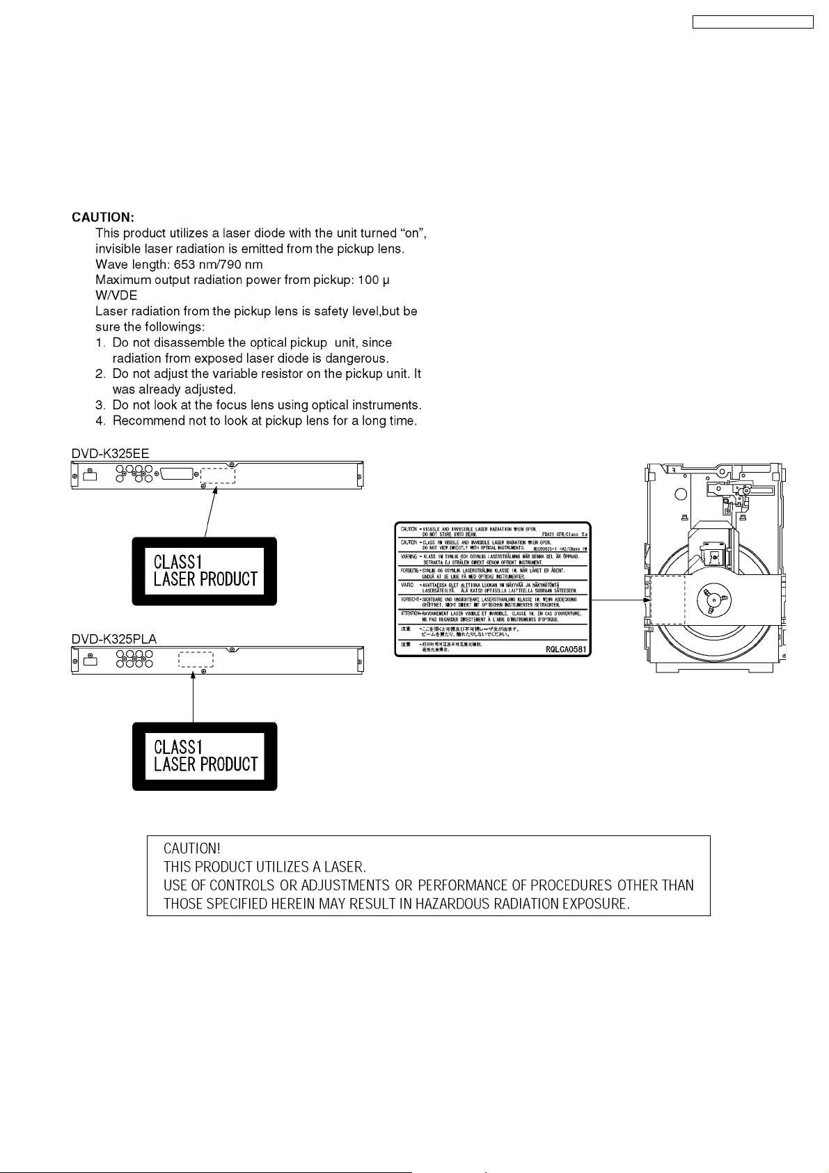
Pickup
Wave length: 653 nm/790 nm
Laser power: CLASS 1/CLASS 1M
Note:
Specifications are subject to change without notice.
Mass and dimensions are approximate.
Solder:
This model uses lead free solder (PbF).
CONTENTS
Page Page
1 IMPORTANT SERVICE INFORMATION
1.1. Notes
1.2. About DivX
1.3. Manual for Customer
2 SAFETY PRECAUTIONS
2.1. GENERAL GUIDELINES
3 PREVENTION OF ELECTRO STATIC DISCHARGE (ESD) TO
ELECTROSTATICALLY SENSITIVE (ES) DEVICES
4 PRECAUTION OF LASER DIODE
5 SERVICE CAUTION BASED ON LEGAL RESTRICTIONS
5.1. General description about Lead Free Solder (PbF)
6 PREVENTION OF STATIC ELECTRICITY DISCHARGE
6.1. Grounding for electrostatic breakdown prevention
6.2. Handling Precautions for Traverse Unit (Optical Pickup)
7 DISASSEMBLING THE CASING AND CHECKING P.C.B.S
7.1. Disassembly Procedure
7.2. Casing Parts and P.C.B. Positions
4
4
4
5
6
6
6
7
7
7
9
9
9
10
10
11
7.3. Top Panel 12
7.4. Front Panel
7.5. Mic P.C.B.
7.6. Operation P.C.B. and Power SW P.C.B.
7.7. Module P.C.B.
7.8. Mechanism Unit
7.9. Rear panel
7.10. Mother P.C.B.
7.11. Service Position
8 ASSEMBLING AND DISASSEMBLING THE MECHANISM UNIT
8.1. Disassembly Procedure
8.2. Traverse Unit
8.3. Tray
8.4. Loading section
8.5. Loading motor P.C.B.
8.6. TRV Unit
2
12
12
12
12
13
13
13
14
15
15
15
16
17
18
19

DVD-K325EE / DVD-K325P LA
9 SELF-DIAGNOSIS FUNCTION AND SERVICE MODES 22
9.1. Optical Pickup Breakdown Diagnosis
9.2. Service Mode Table 1
9.3. DVD Self Diagnostic Function-Error Code
9.4. Last Error Code saved during NO PLAY
9.5. Service mode table 2
9.6. Sales demonstrat ion lock function
9.7. Handling After Completing Repairs
10 SERVICE PRECAUTIONS
10.1. Recovery after the DVD player is repaired.
10.2. Firmware version-up of the DVD player
11 ADJUSTMENT PROCEDURES
11.1. Service Tools and Equipment
11.2. Important points in electrical adjustment
11.3. Storing and Handling Test Discs
12 ABBREVIATIONS
13 VOLTAGE CHART
13.1. MOTHER P.C.B.
13.2. MODULE P.C.B.
13.3. MIC P.C.B.
14 BLOCK DIAGRAM
14.1. OVERALL BLOCK DIAGRAM
14.2. POWER SUPPLY BLOCK DIAGRAM
14.3. SERVO BLOCK DIAGRAM
14.4. VIDEO BLOCK DIAGRAM (DVD-K325EE)
14.5. VIDEO BLOCK DIAGRAM (DVD-K325PLA)
14.6. AUDIO BLOCK DIAGRAM
22
23
23
24
25
28
28
29
29
29
30
30
30
30
31
33
33
34
35
37
37
38
39
40
42
43
15 INTERCONNECTION SCHEMATIC DIAGRAM & SCHEMATIC
DIAGRAM NOTES
15.1. INTERCONNECTION SCHEMATIC DIAGRAM
45
45
15.2. SCHEMATIC DIAGRAM NOTES
16 SCHEMATIC DIAGRAM
16.1. POWER SUPPLY SECTION (MOTHER P.C.B. (1 / 2))
SCHEMATIC DIAGRAM (DVD-K325EE)
16.2. POWER SUPPLY SECTION (MOTHER P.C.B. (1 / 2))
SCHEMATIC DIAGRAM (DVD-K325PLA)
16.3. FRONT & AV OUT SECTION (MOTHER P.C.B. (2 / 2))
SCHEMATIC DIAGRAM (DVD-K325EE)
16.4. FRONT & AV OUT SECTION (MOTHER P.C.B. (2 / 2))
SCHEMATIC DIAGRAM (DVD-K325PLA)
16.5. MODULE SCHEMATIC DIAGRAM
16.6. MIC SCHEMATIC DIAGRAM
17 PRINT CIRCUIT BOARD
17.1. MOTHER P.C.B. (DVD-K325EE)
17.2. MOTHER P.C.B. ADDRESS INFORMATION (DVD-
K325EE)
17.3. MOTHER P.C.B. (DVD-K325PLA)
17.4. MOTHER P.C.B. ADDRESS INFORMATION (DVD-
K325PLA)
17.5. MODULE P.C.B. (1/2)
17.6. MODULE P.C.B. (2/2)
17.7. MODULE P.C.B. ADDRESS INFORMATION
18 EXPLODED VIEWS
18.1. CASING PARTS & MECHANISM SECTION EXPLODED
VIEW
18.2. MECHANISM SECTION EXPLODED VIEW
18.3. PACKING & ACCESSORIES SECTION EXPLODED
VIEW
19 REPLACEMENT PARTS LIST
46
47
47
48
49
52
55
57
59
59
60
61
62
63
64
65
67
67
68
69
70
3
DVD-K325EE / DVD-K325P LA
1 IMPORTANT SERVICE INFORMATION
1.1. Notes
When you replace FLASH-ROM or exchange MODULE P.C.B., you have to take "Manu al for customer" to the customer with unit.
(also in the case of unit exchange)
Please take and use "Manual for customer" from below.
1. Come with MODULE P.C.B. or FLASH-ROM (Service part).
2. Make a photocopy section 1.3. "Manual for customer" on this service manual.
"Manual for customer" has important information for "DivX Video-on-Dem and Service" user.
Please don´t forget take it to the customer with unit!
1.2. About DivX
1.2.1. DivX
A video compression format developed by DivXNetworks, Inc. that compresses video files without any considerable loss of video
quality.
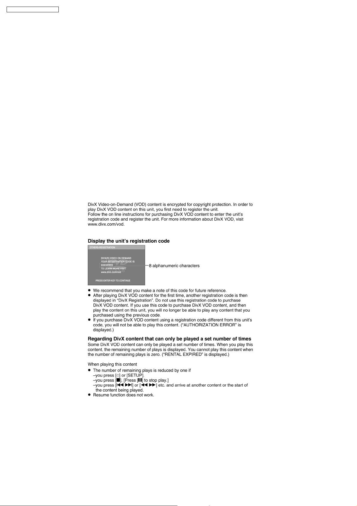
1.2.2. About DivX Video-on-Demand Content
4

1.3. Manual for Customer
Warning for Customers Who Use the DivX Video-on-Demand content.
1. The registration code has been changed for the repair of the product or the product
exchange.
2. Obtain and register a new registration code, otherwise you will no longer be able to
play DivX Video-on-Demand content.
DVD-K325EE / DVD-K325P LA
3. Follow the procedure on the DivX Video-on-Demand web site to register at
http://vod.divx.com/..
* If you do not use the DivX Video-on-Demand content, please ignore this warning.
5
DVD-K325EE / DVD-K325P LA
2 SAFETY PRECAUTIONS
2.1. GENERAL GUIDELINES
1. When servicing, observe the original lead dress. If a short circuit is found, replace all parts which have been overheated or
damaged by the short circuit.
2. After servicing, see to it that all the protective devices such as insulation barriers, insulation papers shields are properly
installed.
3. After servicing, make the following leakage current checks to prevent the customer from being exposed to shock hazards.
2.1.1. LEAKAGE CURRENT COLD
CHECK
1. Unplug the AC cord and connect a jumper between the two
prongs on the plug.
2. Measure the resistance value, with an ohmmeter, between
the jumpered AC plug and each exposed metallic cabine t
part on the equipment such as screwheads, connectors,
control shafts, etc. When the exposed metallic part has a
return path to the chassis, the reading should be between
1MΩ and 5.2MΩ.
When the exposed metal does not have a return path to the
chassis, the reading must be
Figure 1
.
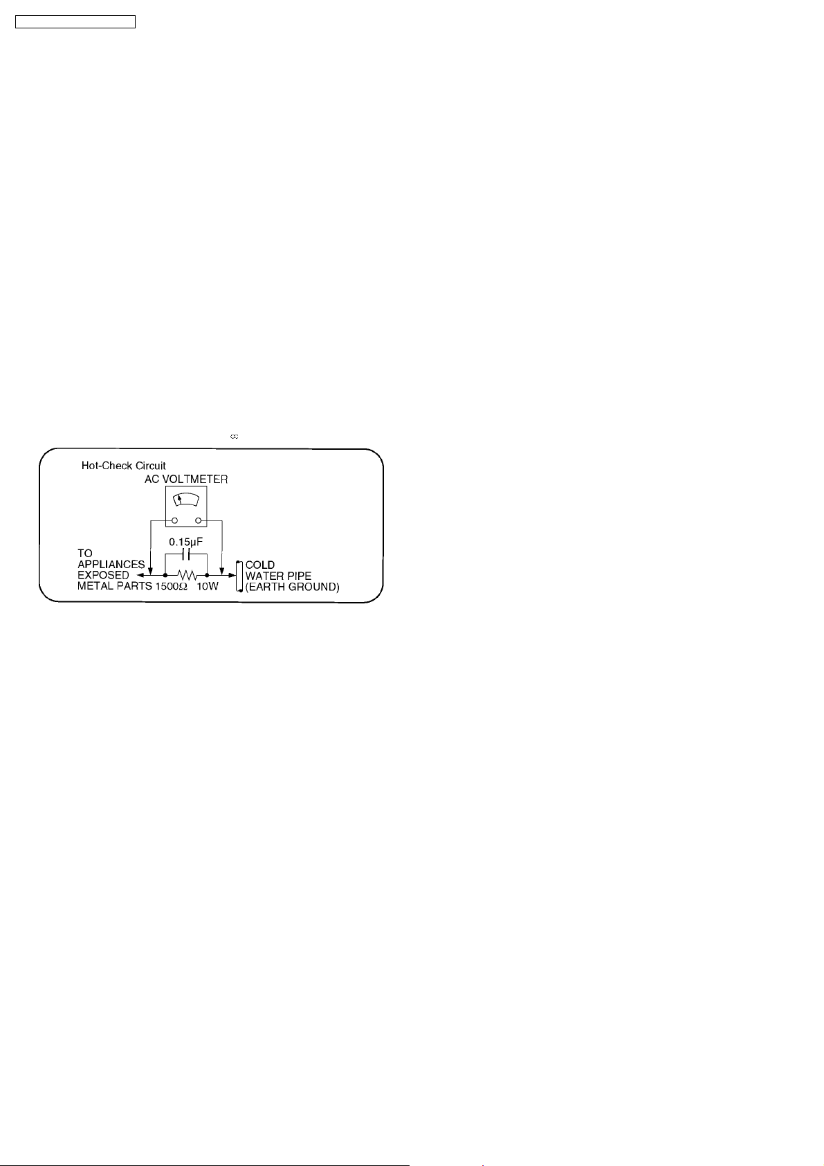
2.1.2. LEAKAGE CURRENT HOT CHECK
(See Figure 1 .)
1. Plug the AC cord directly into the AC outlet. Do not use an
isolation transformer for this check.
2. Connect a 1.5kΩ, 10 watts resistor, in parallel with a 0.15µF
capacitors, between each exposed metallic part on the set
and a good earth ground such as a water pipe, as shown in
Figure 1.
3. Use an AC voltmeter, with 1000 ohms/volt or more
sensitivity, to measure the potential across the resistor.
4. Check each exposed metallic part, and measure the
voltage at each point.
5. Reverse the AC plug in the AC outlet and repeat each of the
above measurements.
6. The potential at any point should not exceed 0.75 volts
RMS. A leakage current tester (Simpson Model 229 or
equivalent) may be used to make the hot checks, leakage
current must not exceed 1/2 milliamp. In case a
measurement is outside of the limits specified, there is a
possibility of a shock hazard, and the equipment should be
repaired and rechecked before it is returned to the
customer.
3 PREVENTION OF ELECTRO STATIC DISCHARGE (ESD)
TO ELECTROSTATICALLY SENSITIVE (ES) DEVICES
Some semiconductor (solid state) devices can be damaged easily by static electricity. Such components commonly are called
Electrostatically Sensitive (ES) Devices. Examples of typical ES devices are integrated circuits and some field-effect transistors and
semiconductor "chip" components. The following techniques should be used to help reduce the incidence of component damage
caused by electro static discharge (ESD).
1. Immediately before handling any semiconductor component or semiconductor-equipped assembly, drain off any ESD on your
body by touching a known earth ground. Alternatively, obtain and wear a commercially available discharging ESD wrist strap,
which should be removed for potential shock reasons prior to applying power to the unit under test.
2. After removing an electrical assembly equipped with ES devices, place the assembly on a conductive surface such as alminum
foil, to prevent electrostatic charge build up or exposu re of the assembly.
3. Use only a grounded-tip soldering iron to solder or unsolder ES devices.
4. Use only an anti-static solder removal device. Some solder removal devices not classified as "anti-static (ESD protected)" can
generate electrical charge sufficient to damage ES devices.
5. Do not use freon-propelled chemicals. These can generate electrical charges sufficient to damage ES devices.
6. Do not remove a replacement ES device from its protective package until immediately before you are ready to install it. (Most
replacement ES devices are packaged with leads electrically shorted together by conductive foam, alminum foil or comparable
conductive material).
7. Immediately before removing the protective material from the leads of a replacement ES device, touch the protective material
to the chassis or circuit assembly into which the device will be installed.
6
DVD-K325EE / DVD-K325P LA
Caution
Be sure no power is applied to the chassis or circuit, and observe all other safety precautions.
8. Minimize bodily motions when handlin g unpackaged replacement ES devices. (Otherwise hamless motion such as the brushing
together of your clothes fabric or the lifting of your foot from a carpeted floor can generate static electricity (ESD) sufficient to
damage an ES device).
4 PRECAUTION OF LASER DIODE
5 SERVICE CAUTION BASED ON LEGAL RESTRICTIONS
5.1. General description about Lead Free Solder (PbF)
The lead free solder has been used in the mounting process of all electrical components on the printed circuit boards used for this
equipment in considering the globally environmental conservation.
The normal solder is the alloy of tin (Sn) and lead (Pb). On the other hand, the lead free solder is the alloy mainly consists of tin
(Sn), silver (Ag) and Copper (Cu), and the melting point of the lead free solder is higher approx.30°C (86°F) more than that of the
7

DVD-K325EE / DVD-K325P LA
normal solder.
Definition of PCB Lead Free Solder being used
Service caution for repair work using Lead Free Solder (PbF)
· The lead free solder has to be used when repairing the equipment for which the lead free solder is used. (Definition: The
letter of “PbF” is printed on the PCB using the lead free solder.)
· To put lead free solder, it should be well molten and mixed with the original lead free solder.
· Remove the remaining lead free solder on the PCB cleanly for soldering of the new IC.
· Since the melting point of the lead free solder is higher than that of the normal lead solder, it takes the longer time to melt
the lead free solder.
· Use the soldering iron (more than 70W) equipped with the temperature control after setting the temperature at 350±30°C
(662±86°F).
Recommended Lead Free Solder (Service Parts Route.)
The following 3 types of lead free solder are available through the service parts route.
· RFKZ03D01K-----------(0.3mm 100g Reel)
· RFKZ06D01K-----------(0.6mm 100g Reel)
· RFKZ10D01K-----------(1.0mm 100g Reel)
Note
* Ingredient: tin (Sn) 96.5%, silver (Ag) 3.0%, Copper (Cu) 0.5%, Cobalt (Co) / Germanium (Ge) 0.1 to 0.3%
8
DVD-K325EE / DVD-K325P LA
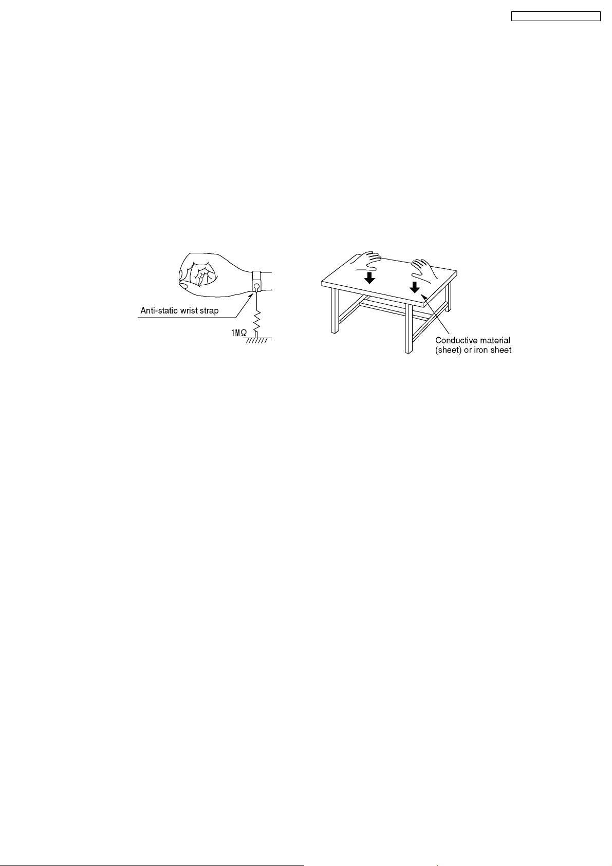
6 PREVENTION OF STATIC ELECTRICITY DISCHARGE
The laser diode in the traverse unit (optical pickup) may brake down due to static electricity of clothes or human body. Use due
caution to electrostatic breakdown when servicing and handling the laser diode.
6.1. Grounding for electrostatic breakdown prevention
Some devices such as the DVD player use the optical pickup (laser diode) and the optical pickup will be damaged by static
electricity in the working environment. Proceed servicing works under the working environment where grounding works is
completed.
6.1.1. Worktable grounding
1. Put a conductive material (sheet) or iron sheet on the area where the optical pickup is placed, and ground the sheet.
6.1.2. Human body grounding
1. Use the anti-static wrist strap to discharge the static electricity form your body.
6.1.3. Handling of optical pickup
1. To keep the good quality of the optical pickup maintenance parts during transportation and before installation, the both ends of
the laser diode are short-circuited. After replacing the parts with new ones, remove the short circuit according to the correct
procedure. (See this Service Manual.)
2. Do not use a tester to check the laser diode for the optical pickup. Failure to do so will damage the laser diode due to the power
supply in the tester.
6.2. Handling Precautions for Traverse Unit (Optical Pickup)
1. Do not give a considerable shock to the traverse unit (optical pickup) as it has an extremely high-precise structure.
2. When replacing the optical pickup, install the flexible cable and cut its short land with a nipper. See the optical pickup
replacement procedure in this Service Manual. Before replacing the traverse unit, remove the short pin for preventing static
electricity and install a new unit. Connect the connector as short times as possible.
3. The flexible cable may be cut off if an excessive force is applied to it. Use caution when handlin g the cable.
4. The half-fixed resistor for laser power adjustment cannot be adjusted. Do not turn the resistor.
9
DVD-K325EE / DVD-K325P LA
7 DISASSEMBLING THE CASING AND CHECKING P.C.B.S
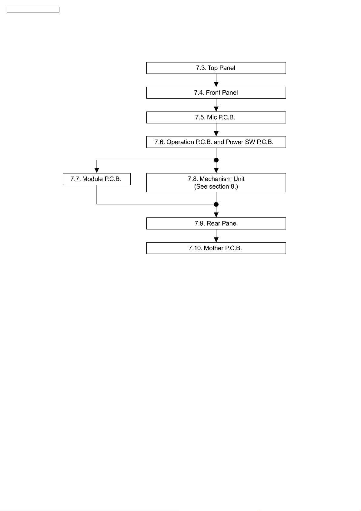
7.1. Disassembly Procedure
10
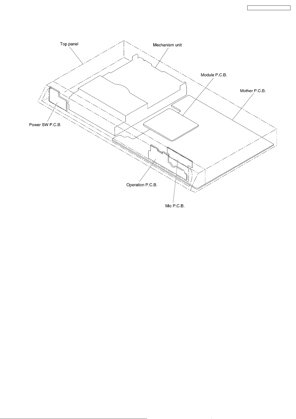
7.2. Casing Parts and P.C.B. Positions
DVD-K325EE / DVD-K325P LA
11
DVD-K325EE / DVD-K325P LA
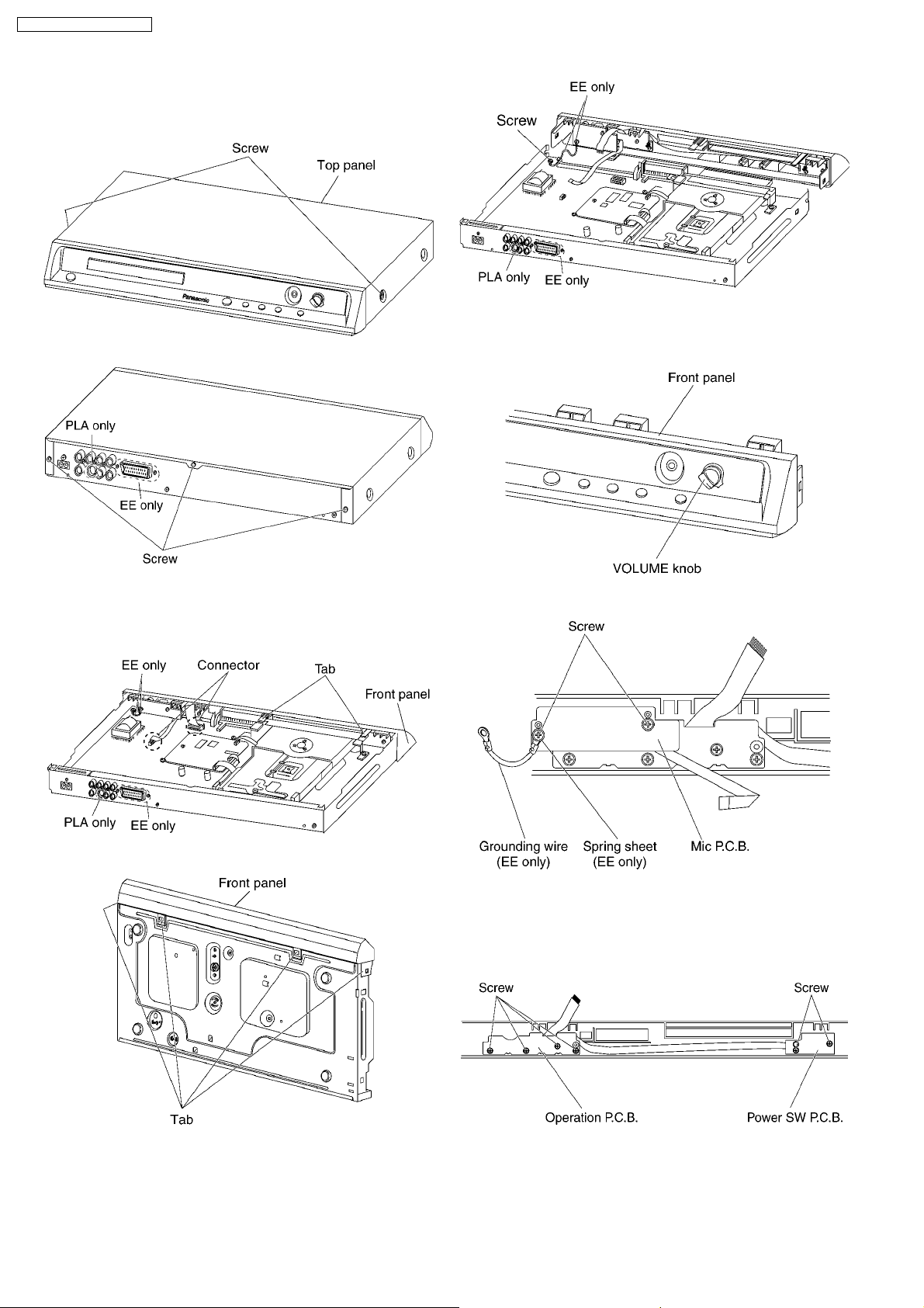
7.3. Top Panel
1. Unscrew the screws.
7.5. Mic P.C.B.
1. Unplug the knob.
7.4. Front Panel
1. Release the tabs and connector.
2. Release the tabs.
2. Unscrew the screws.
7.6. Operation P.C.B. and Power
SW P.C.B.
1. Unscrew the screws.
3. Unscrew the screw.
7.7. Module P.C.B.
1. Remove the connectors.
2. Unscrew the screws.
12
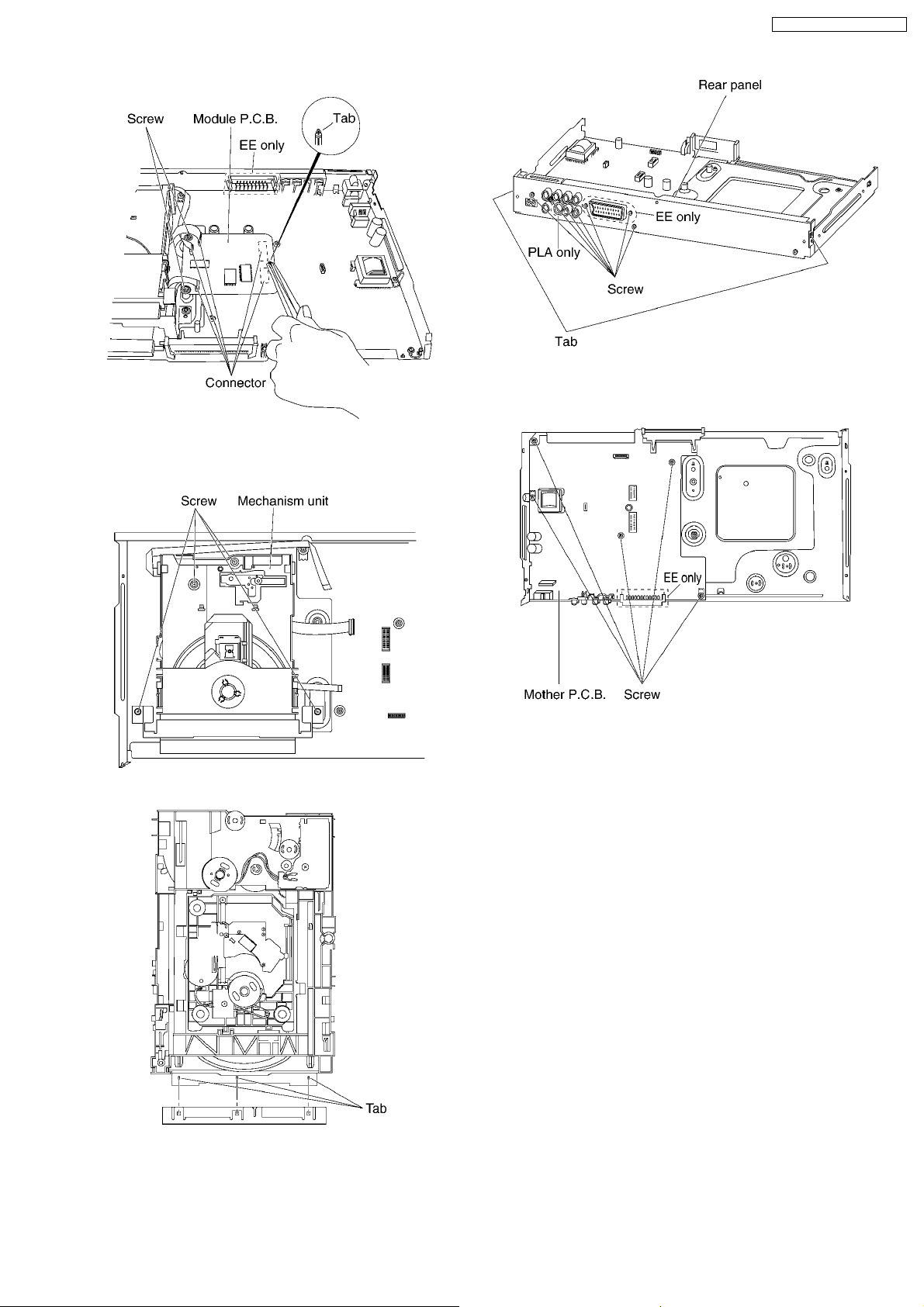
3. Press each tab with the nipper to module PCB vertically.
7.8. Mechanism Unit
DVD-K325EE / DVD-K325P LA
7.10. Mother P.C.B.
1. Unscrew the screws.
1. Unscrew the screws.
2. Release the tabs.
7.9. Rear panel
1. Unscrew the screws.
2. Release the tabs.
13
DVD-K325EE / DVD-K325P LA
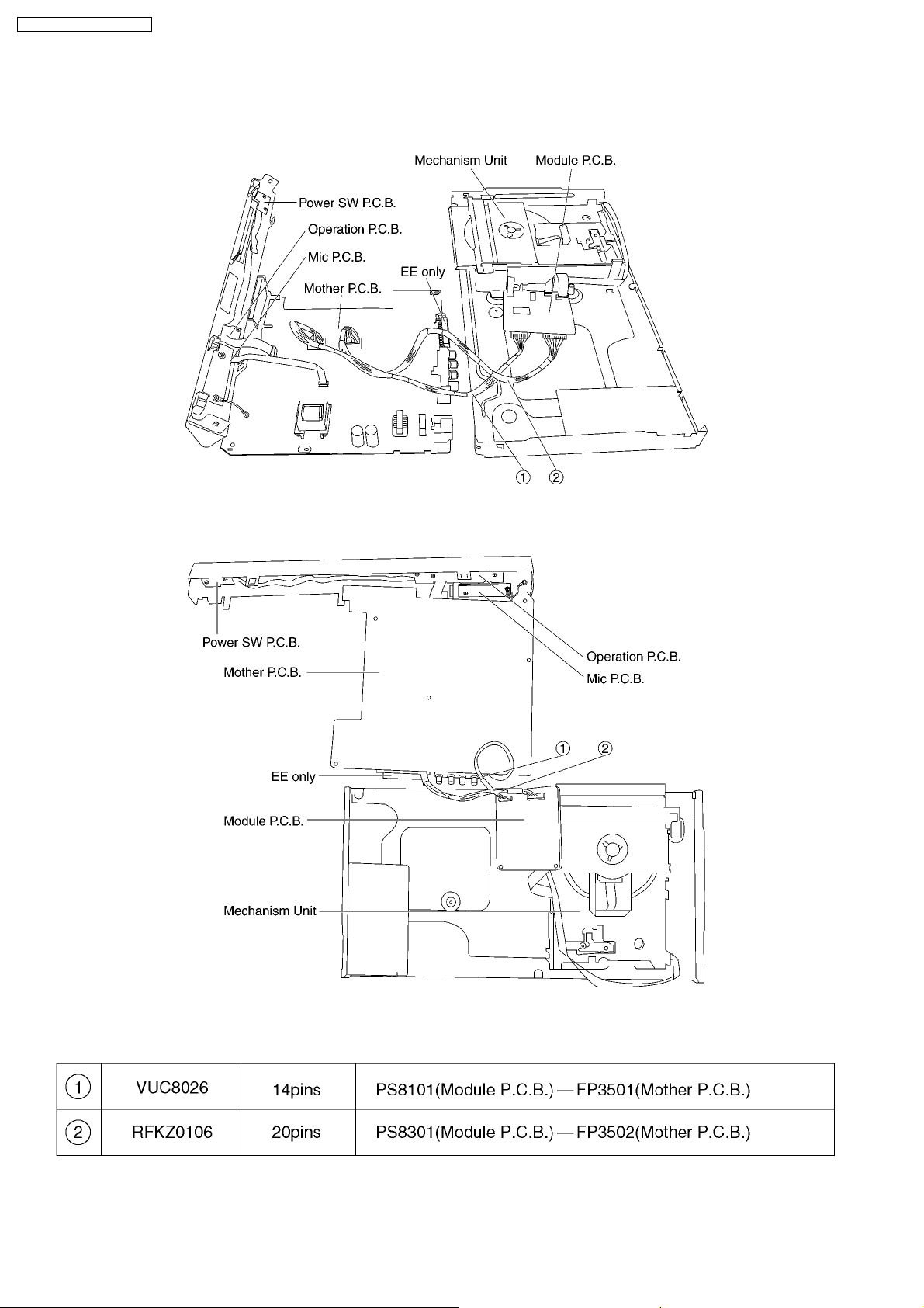
7.11. Service Position
7.11.1. Servicing position of the Module P.C.B.
7.11.2. Servicing position of the Mother P.C.B.
7.11.3. List of the Extension Cables
14
8 ASSEMBLING AND
DISASSEMBLING THE
MECHANISM UNIT
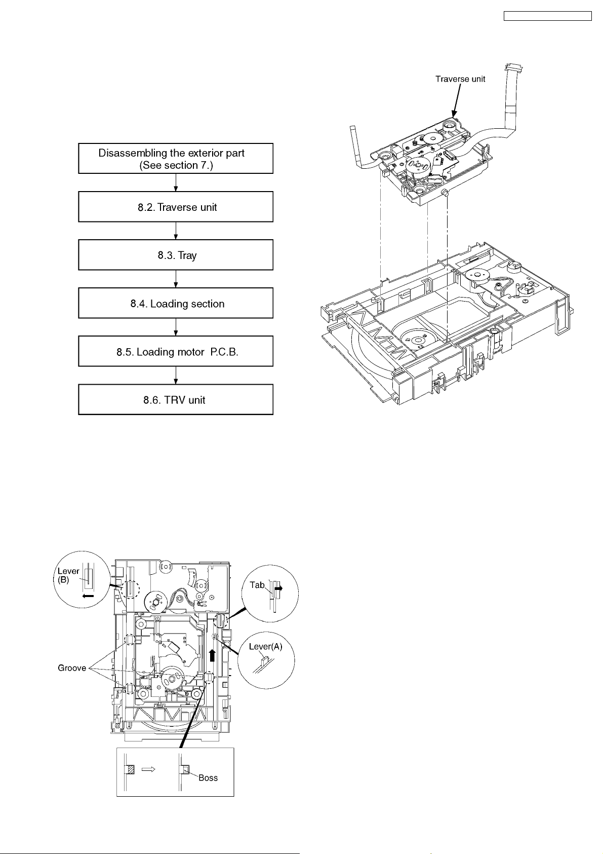
8.1. Disassembly Procedure
DVD-K325EE / DVD-K325P LA
4. Remove the traverse unit.
8.2. Traverse Unit
1. Slide the lever (A) in the arrow direction (to the opposite
side) till it stops.
2. Slide the lever (A) further by bending the tab at the right
side of the lever A in the right direction. (The right groove
opens and the boss becomes seen.)
3. Open the lever (B) to left. (The 2 grooves at the left side
open.)
15
DVD-K325EE / DVD-K325P LA
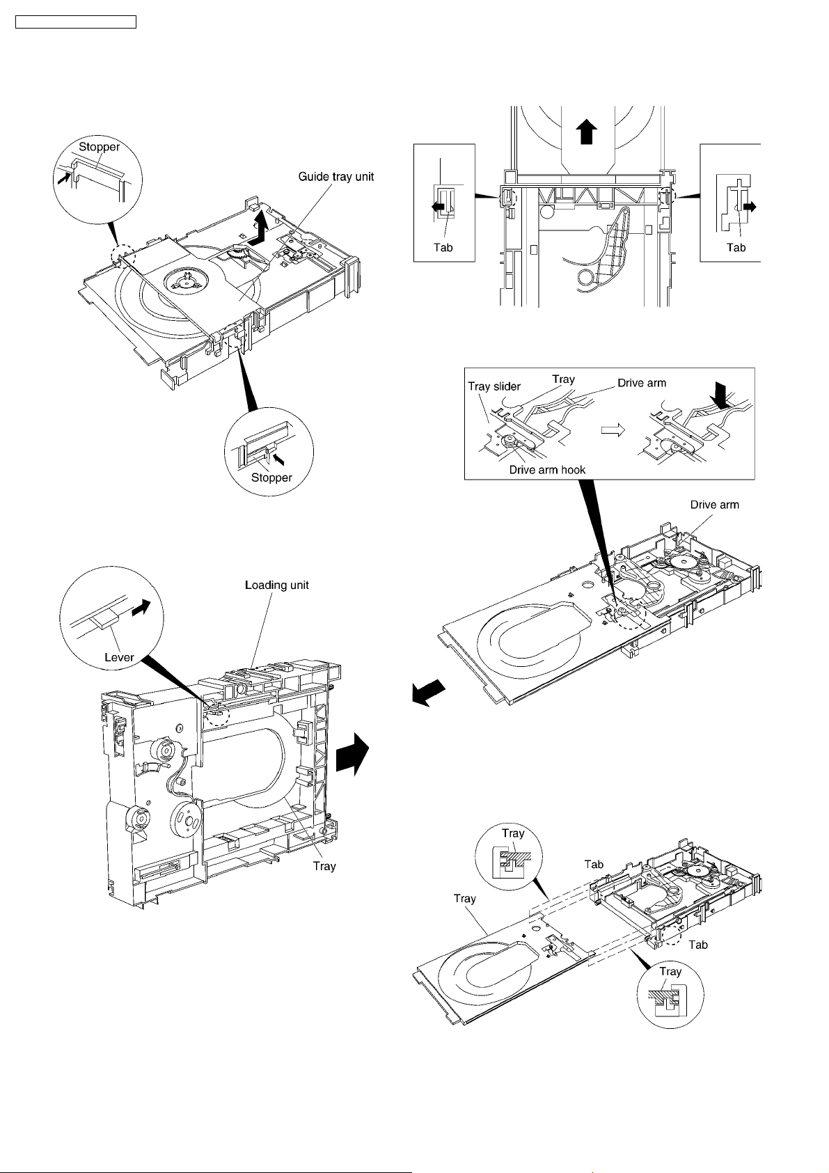
8.3. Tray
1. Slide the guide tray unit while pressing the stopper in the
arrow direction, and remove the guide tray unit.
5. Remove the drive arm concave phase from the tray slider
and tray.
2. Raise the loading unit.
3. Slide the lever in the arrow direction till it stops and pull the
tray out.
<Assembling the tray unit>
1. Insert a part of the tray into the unit sliding over the
groove on the mechanical chassis unit.
2. Insert the tray to the point before the tab of the
mechanical chassis unit.
4. Spread the tabs at the both sides and pull the tray out. (The
tray slides a little forward and stops.)
3. Hook the drive arm concave phase over the tray and the
tray slider.
4. Press in the tray.
16
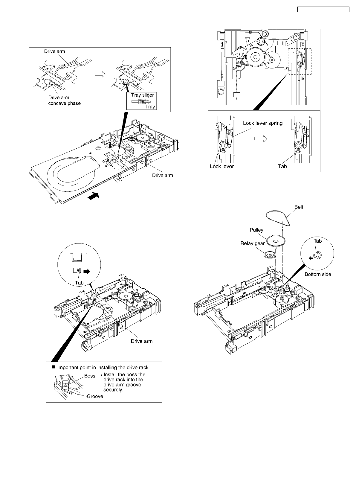
5. Make sure that the tray and the drive arm move
smoothly.
DVD-K325EE / DVD-K325P LA
4. Remove the belt.
5. Unlock the tab and remove the pulley.
6. Remove the relay gear.
8.4. Loading section
1. Spread the tabs at the both sides and push out the drive
arm shaft.
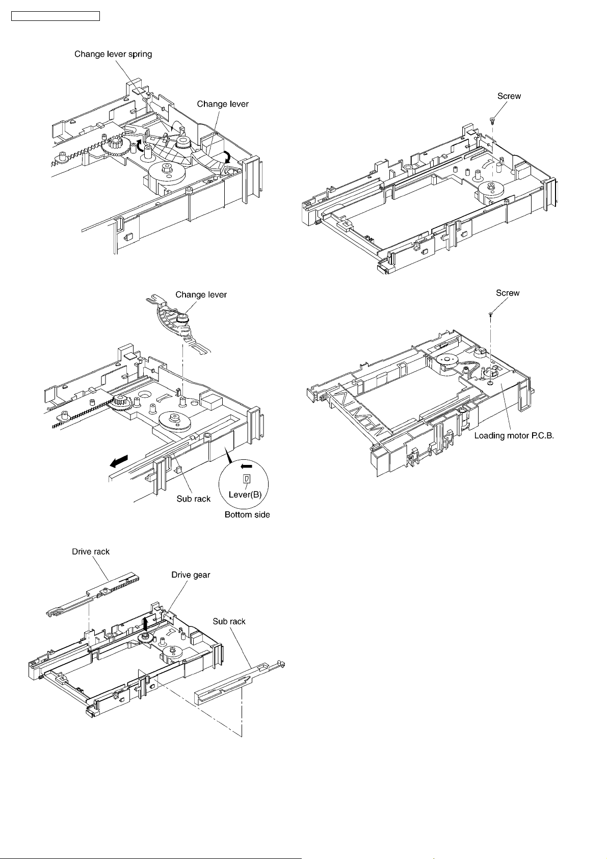
7. Turn the change lever in the arrow direction till it stops.
8. Hook the change lever spring on the change lever project
part temporarily.
2. Hook the lock lever spring on the lock lever projection part
temporarily.
3. Unlock the tab and remove the lock lever.
17
DVD-K325EE / DVD-K325P LA
9. Pull the lever (B) in the bottom side to your side and remove
the change lever.
8.5. Loading motor P.C.B.
1. Unscrew the screws.
10. Remove the drive rack, the sub rack and the drive gear.
18
DVD-K325EE / DVD-K325P LA
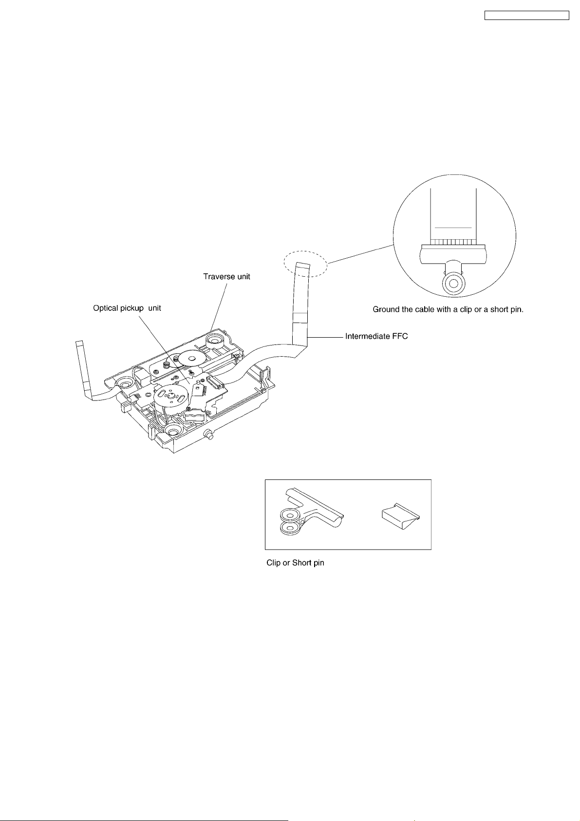
8.6. TRV Unit
8.6.1. Cautions to Be Taken in Handling the TRV Unit
The laser diode in the TRV unit may be damaged due to electrostatic discharge generating from clothes or human body. Use due
caution to electrostatic discharge damage when servicing the laser diode.
1. Do not give a considerable shock to the TRV unit as it has an extremely high-precise structure.
2. To prevent the laser diode from the electrostatic discharge damage, the Intermediate FFC of the TRV unit removed from the
PCB should be short-circuited with a short pin or a clip.
3. The Intermediate FFC may be cut off if an excessive force is applied to it. Use caution when handling the Intermediate FFC.
19
DVD-K325EE / DVD-K325P LA
8.6.2. Procedure for Disassembling the
TRV Unit
Notice
1. This section aims to focus on the disassembling
methods of some parts in the case that no damage is
occurred to optical pickup units.
2. When the optical pickup unit is defective, the overall
traverse unit needs replacement.
3. Please note that appropriate actions needs to be taken
to prevent static damage.
Caution
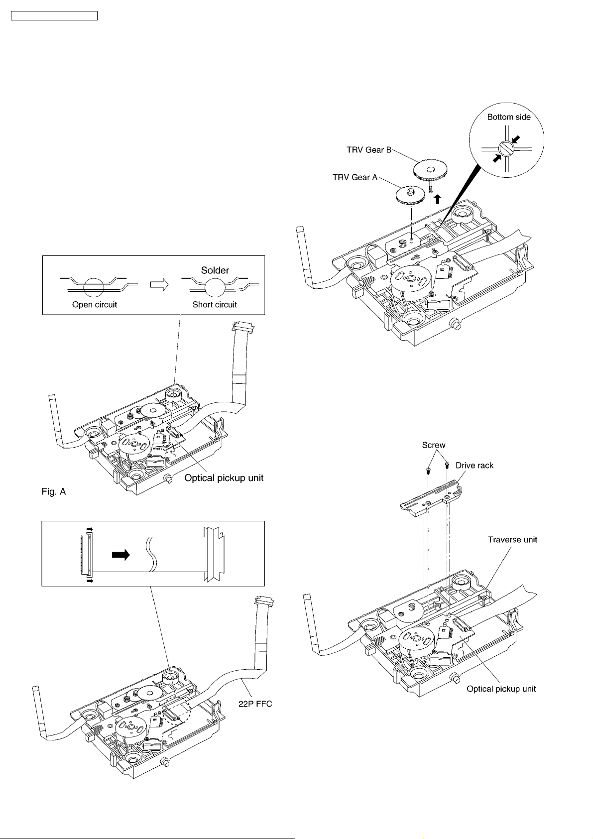
Insert the short pin into the FFC of the optical pickup unit.
(See “Caution to be taken in handlin g the TRV Unit”)
1. Before changing 22P FFC, please weld the short-circuit
solder. (refer to Fig. A)
After changing the 22P FFC, please remove the solder.
(refer to Fig. B)
3. Push the tabs on the back and remove the TRV Gear B and
A.
2. Remove the connecter, take out the 22P FFC.
4. Unscrew the screws.
5. Remove the drive rack.
Caution
Do not dissemble drive rack fixing screws repeatly,
otherwise the screws may hard to tighten and affect the
accuracy of optical pickups consequently.
6. Remove the solders of the SP motor and the TRV motor.
20
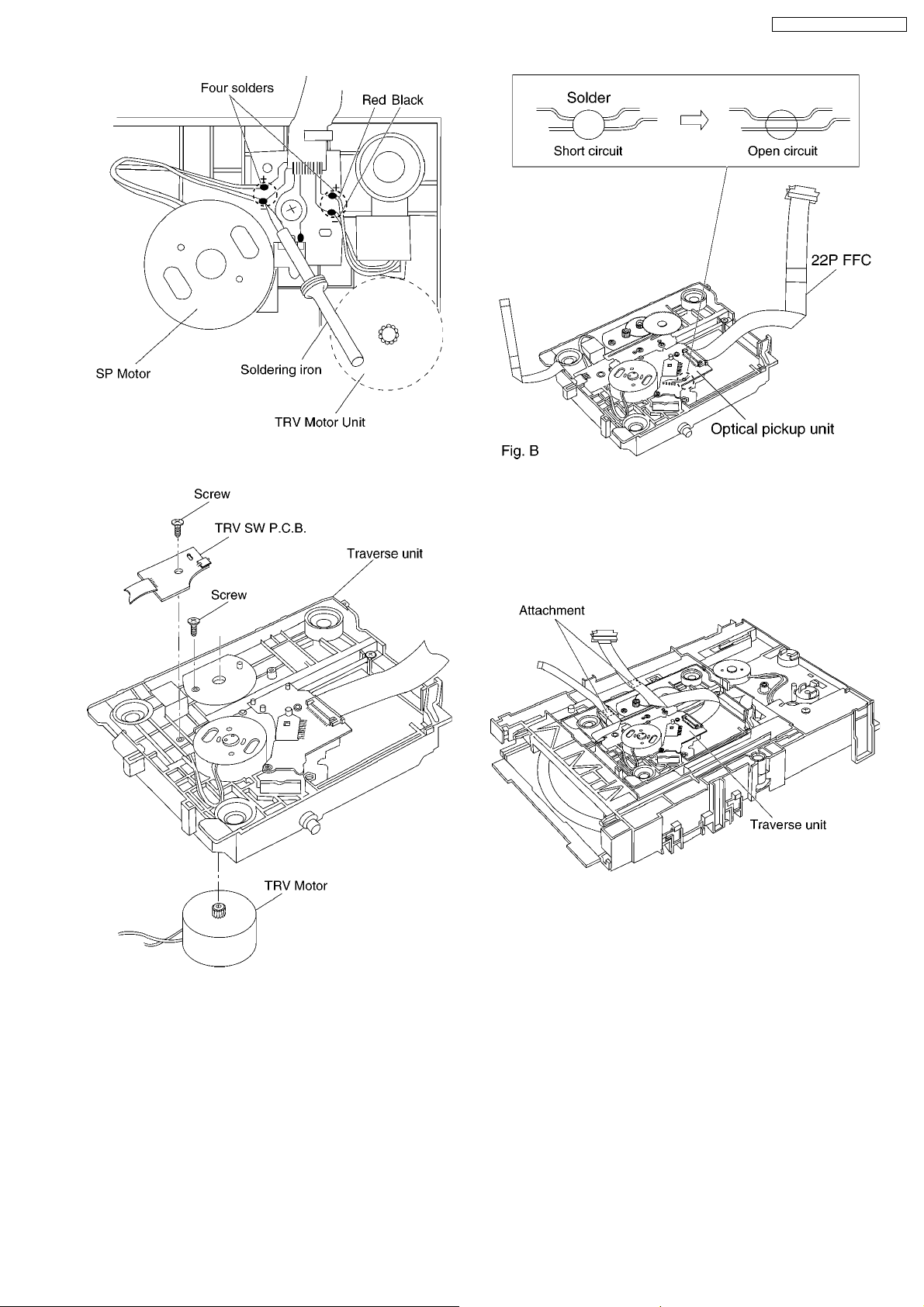
7. Unscrew the screws, then remove the TRV Motor and TRV
SW P.C.B. Unit.
DVD-K325EE / DVD-K325P LA
Caution
a. Do not give a considerable shock to the optical
pickup unit as it has an extremely high-precise
structure.
b. Do not touch the lens in the optical pickup unit.
2. The FFC is fixed as shown below.
<Assembling the TRV unit>
1. After replacing the TRV Unit and connecting the 22P
FFC, remove the solder on the optical pickup unit.
21
DVD-K325EE / DVD-K325P LA
9 SELF-DIAGNOSIS FUNCTION AND SERVICE MODES
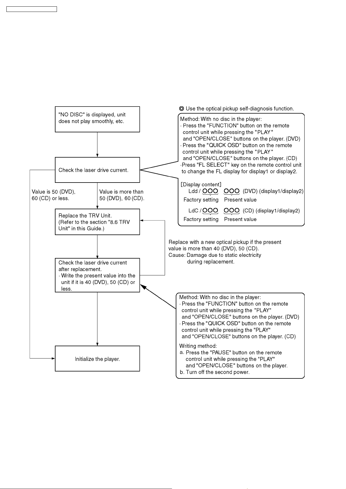
9.1. Optical Pickup Breakdown Diagnosis
The optical pickup self-diagnosis function has been included in this unit. When repairing, use the following procedure for effectiv e
Self-diagnosis. Be sure to use the self-diagnosis function before replacing the TRV Unit when "NO DISC" is displayed. As a
guideline, you should replace the TRV Unit when the value of the laser drive current is more than 55.
Note:
Press the power button to turn on the power, and check the value within three minutes before the unit warms up. (Otherwise,
the result will be incorrect.)
22
DVD-K325EE / DVD-K325P LA
9.2. Service Mode Table 1
The service modes can be activated by pressing various button combination on the player and remote control unit. please carry out
your operation based on the remote control supplied with Panasonic DVD player of previous models.
Player buttons Remote control unit buttons Application Note
PLAY
+
OPEN/CLOSE
0 Displaying the UHF display F_ _ _ Refer to section 9.3. Self-
5 Jitter check, tilt adjustment
*Display shows J_xxx/yyy_zz
"yyy" and "zz" shown to the right have nothing to do with the jitter
value. "yyy" is the error counter, while "zz" isthe focus drive
value.
6 Checking the region numbers and broadcast system
7 Checking the program version Check the IC8651 FLASH
9 Lighting Confirmation Function of Display Tube
FUNCTION Checking the laser drive current Refer to section 9.1.
PAUSE Writing the laser drive current value after replacing the optical
pickup (do not use for anything other than optical pickup
replacement)
POWER Initializing the DVD player
(restoring factory preset settings)
Diagnosis Function (UHF
Display).
ROM program.
Optical Pickup
Replacement Procedure.
Refer to section 9.5.
Initializing the DVD
player.
9.3. DVD Self Diagnostic Function-Error Code
Error Code Error Content Additional error explanation Defect 1 Defect 2 Defect 3 Defect 4
U11 Focus error Focus coil, FE singal error TRV Unit DV5.0
H01 Tray loading error LD motor error, DV5.0 (IC8001) error LD Motor IC8251
H02 Spindle servo error (Spindle servo, DV5.0 (IC8001) SP motor, CLV
H03 Traverse servo error Traverse servo, DV5.0 (IC8001) , TRV motor
H04 Tracking servo error Tracking coil, DV5.0 (IC8001) error TRV Unit DV5.0
H05 Seek error TRV Motor, IC8251 error TRV Motor IC8251
H07 Spindle motor drive
error
F893 FROM falsification Firmware soft error, DV5.0 (IC8001) error FROM
F895 Language area
abnormality
F897 initialize is not
completed
servo error)
error
SP motor current error, IC8251 error TRV Unit IC8251
Firm version agreement check for factory preset
setting failure prevention
Initialize completion check for factory preset
setting failure prevention
LD Motor DV5.0
TRV Motor DV5.0
(IC8651)
FROM
(IC8651)
Note:
An error code will be canceled if a power supply is turned OFF.
*1: When FROM or Module P.C.B. is replaced, be sure to write the present value into the player as the initial setting of laser
drive current. (Refer to section 9.5 initial setting of laser drive current.)
Writing method:
a. Press the "PAUSE" button on the remote control unit while pressing the "PLAY" and "OPEN/CLOSE" buttons on the player.
b. Turn off the second power.
(*1)
(*1)
(IC8001)
(IC8001)
(IC8001)
(IC8001)
DV5.0
(IC8001)
23
 Loading...