

Panasonic DMRES-46-VP, DMRES-45-VP Service manual
DMR-ES45VP
DMR-ES46VP
Vol. 1
Colour
(S).......................Silver Type
ORDER NO.VR0603003CE
B24
DVD Recorder
© 2006 Matsushita Electric Industrial Co., Ltd. All
rights reserved. Unauthorized copying and
distribution is a violation of law.
DMR-ES45VP / DMR-ES46VP
CONTENTS
Page Page
1 Safety Precaution 4
1.1. General guidelines
1.2. Caution for fuse replacement
2 Warning
2.1. Prevention of Electrostatic Discharge (ESD) to
Electrostatic Sensitive (ES) Devices
2.2. Precaution of Laser Diode
2.3. Service caution based on legal restrictions
3 Service Navigation
3.1. Service Information
4 Specifications
5 Features
5.1. HDAVI Control (HDMI Link)
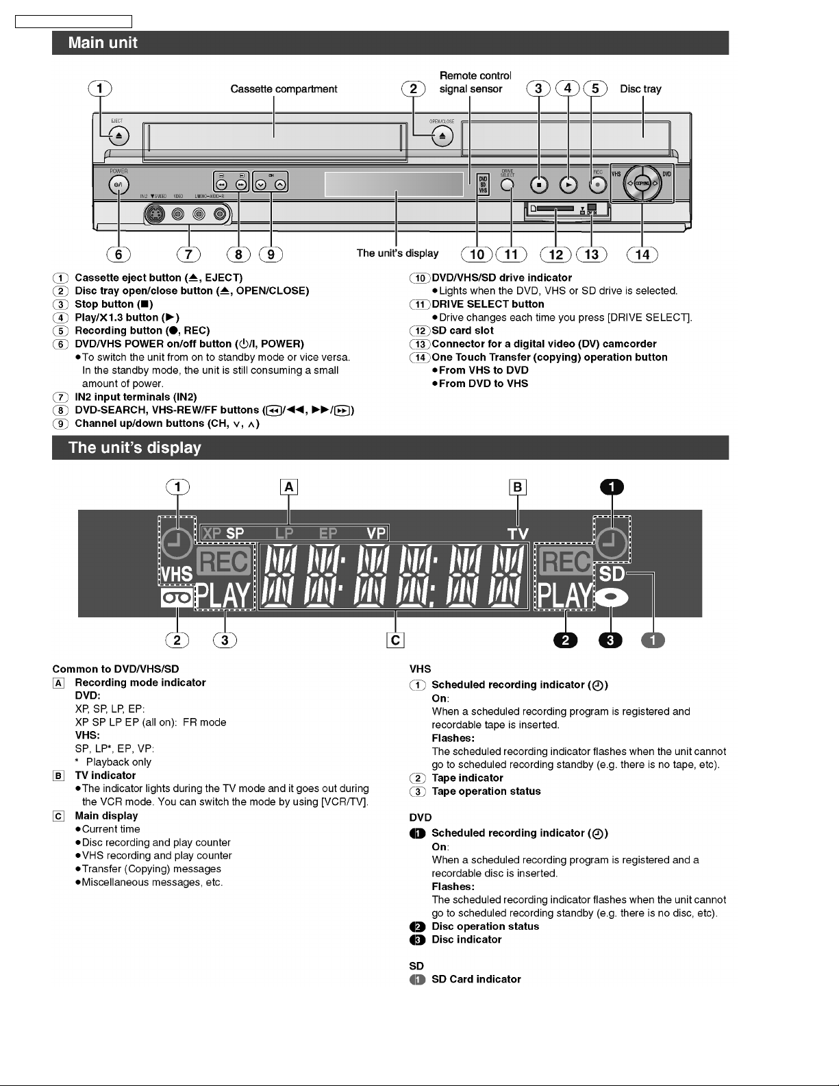
6 Location of Controls and Components
6.1. Each Buttons
7 Operation Instructions
7.1. (DVD) Taking out the Disc from RAM-Drive Unit when the
Disc cannot be ejected by OPEN/CLOSE button
7.2. (VHS) Removing Cassette Tape manually
8 Service Mode
8.1. (DVD) Self-Diagnosis and Special Mode Setting
8.2. (VHS) Self-Diagnosis and Special Mode Setting
9 Service Fixture & Tools
10 Assem blin g and Disassembling
10.1. Disassembly Flow Chart
10.2. P.C.B. Positions
10.3. Caution with inserting cassette tape when disassembling
the unit
10.4. Top Case
10.5. Front Panel
10.6. Front (L) P.C.B. & Front (R) P.C.B.
10.7. RAM / Digital P.C.B. Module
10.8. SD Card/DV Jack P.C.B.
10.9. VTR Mechanism Unit
10.10. Rear Panel & Fan Motor
10.11. HDMI P.C.B.
10.12. Power & Digital I/F P.C.B.
10.13. Main P.C.B.
11 Meas u remen ts and Adjustments
11.1. Service Positions
11.2. Caution for Replacing Parts
11.3. Standard Inspection Specifications after Making Repairs
12 Blo ck Diagram
12.1. Power Supply Block Diagram
12.2. Analog Video Block Diagram
12.3. Analog Audio Block Diagram
10
10
13
13
15
15
16
18
18
26
32
33
33
34
35
36
36
37
37
39
39
40
40
41
41
42
42
45
48
49
49
51
53
4
4
5
5
6
7
8
8
9
12.4. Analog Timer Block Diagram
12.5. System Control & Servo Block Diagram
12.6. HDMI Block Diagram
13 Sche matic Diagr am
13.1. Interconnection Schematic Diagram
13.2. Power Supply Section (Power & Digital I/F P.C.B.(1/2))
Schematic Diagram (P)
13.3. Digital I/F (1/4) Section (Power & Digital I/F P.C.B.(2/2))
Schematic Diagram (IF)
13.4. Digital I/F (2/4) Section (Power & Digital I/F P.C.B.(2/2))
Schematic Diagram (IF)
13.5. Digital I/F (3/4) Section (Power & Digital I/F P.C.B.(2/2))
Schematic Diagram (IF)
13.6. Digital I/F (4/4) Section (Power & Digital I/F P.C.B.(2/2))
Schematic Diagram (IF)
13.7. Video (1/4) Section (Main P.C.B.(1/4)) Schematic Diagram
Schematic Diagram (V)
13.8. Video (2/4) Section (Main P.C.B.(1/4)) Schematic Diagram
Schematic Diagram (V)
13.9. Video (3/4) Section (Main P.C.B.(1/4)) Schematic Diagram
Schematic Diagram (V)
13.10. Video (4/4) Section (Main P.C.B.(1/4)) Schematic Diagram
Schematic Diagram (V)
13.11. VHS Audio Section (Main P.C.B.(2/4)) Schematic Diagram
(A)
13.12. Syscon/Servo/Timer (1/4) Section (Main P.C.B.(3/4))
Schematic Diagram (S)
13.13. Syscon/Servo/Timer (2/4) Section (Main P.C.B.(3/4))
Schematic Diagram (S)
13.14. Syscon/Servo/Timer (3/4) Section (Main P.C.B.(3/4))
Schematic Diagram (S)
13.15. Syscon/Servo/Timer (4/4) Section (Main P.C.B.(3/4))
Schematic Diagram (S)
13.16. I/O Tuner Section (1/4) (Main P.C.B.(4/4)) Schematic
Diagram (I)
13.17. I/O Tuner Section (2/4) (Main P.C.B.(4/4)) Schematic
Diagram (I)
13.18. I/O Tuner Section (3/4) (Main P.C.B.(4/4)) Schematic
Diagram (I)
13.19. I/O Tuner Section (4/4) (Main P.C.B.(4/4)) Schematic
Diagram (I)
13.20. HDMI Schematic Diagram
13.21. SD Card/DV Jack Schematic Diagram
13.22. Front (R) Schematic Diagram
13.23. Front (L) Schematic Diagram
14 Prin ted Circuit Board
54
55
56
57
57
59
61
62
63
64
65
66
67
68
69
70
71
72
73
75
76
77
78
80
82
83
84
85
2

14.1. Power & Digital I/F P.C.B. 85
14.2. Main P.C.B.
14.3. HDMI P.C.B.
14.4. SD Card/DV Jack P.C.B.
14.5. Front (L) P.C.B., Front (R) P.C.B.
15 Miscellaneous
15.1. Abbreviations
87
16 Appendix for Schematic Diagram
92
93
94
95
16.1. Voltage and Waveform Chart
17 Parts and Exploded Views
17.1. Exploded Views
17.2. Replacement Parts List
DMR-ES45VP / DMR-ES46VP
95
101
101
109
109
113
3
DMR-ES45VP / DMR-ES46VP
1 Safety Precaution
1.1. General guidelines
1. When servicing, observe the original lead dress. If a short circuit is found, replace all parts which have been overheated or
damaged by the short circuit.
2. After servicing, see to it that all the protective devices such as insulation barriers, insulation papers shields are properly
installed.
3. After servicing, make the following leakage current checks to prevent the customer from being exposed to shock hazards.
1.1.1. Leakage current cold check
1. Unplug the AC cord and connect a jumper between the two
prongs on the plug.
2. Measure the resistance value, with an ohmmeter, between
the jumpered AC plug and each exposed metallic cabinet
part on the equipment such as screwheads, connectors,
control shafts, etc. When the exposed metallic part has a
return path to the chassis, the reading should be between
1MW and 5.2MW.
When the exposed metal does not have a return path to the
chassis, the reading must be
Figure 1
.
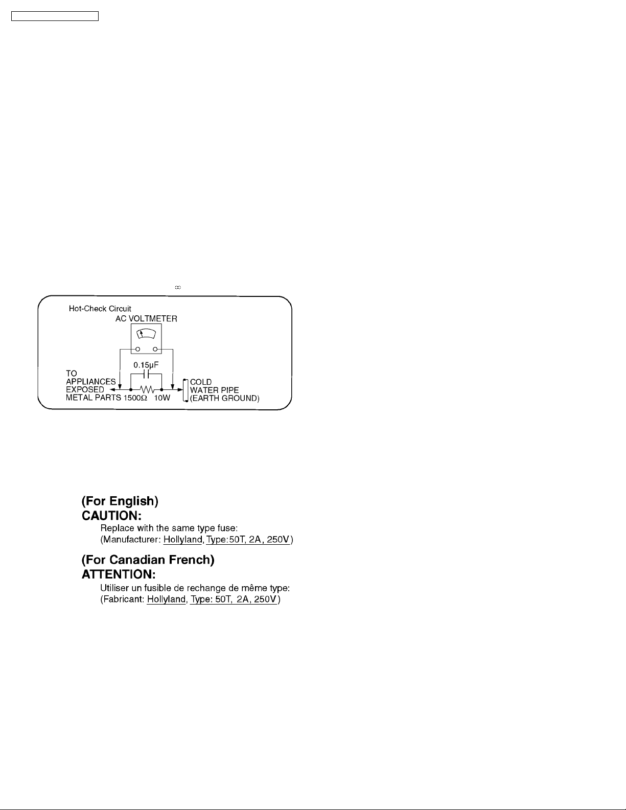
1.1.2. Leakage current hot check
(See Figure 1 .)
1. Plug the AC cord directly into the AC outlet. Do not use an
isolation transformer for this check.
2. Connect a 1.5kW, 10 watts resistor, in parallel with a 0.15µF
capacitors, between each exposed metallic part on the set
and a good earth ground such as a water pipe, as shown in
Figure 1.
3. Use an AC voltmeter, with 1000 ohms/volt or more
sensitivity, to measure the potential across the resistor.
4. Check each exposed metallic part, and measure the
voltage at each point.
5. Reverse the ACplugintheAC outlet andrepeat each of the
above measurements.
6. The potential at any point should not exceed 0.75 volts
RMS. A leakage current tester (Simpson Model 229 or
equivalent) may be used to make the hot checks, leakage
current must not exceed 1/2 milliampere. In case a
measurement is outside of the limits specified, there is a
possibility of a shock hazard, and the equipment should be
repaired and rechecked before it is returned to the
customer.
1.2. Caution for fuse replacement
4
DMR-ES45VP / DMR-ES46VP
2 Warning
2.1. Prevention of Electrostatic Discharge (ESD) to Electrostatic Sensitive
(ES) Devices
Some semiconductor (solid state) devices can be damaged easily by static electricity. Such components commonly are called
Electrostatic Sensitive (ES) Devices. Examples of typical ES devices are integrated circuits and some field-effect transistor-sand
semiconductor "chip" components. The following techniques should be used to help reduce the incidence of component damage
caused by electrostatic discharge (ESD).
1. Immediately before handling any semiconductor component or semiconductor-equipped assembly, drain off any ESD on your
body by touching a known earth ground. Alternatively, obtain and wear a commercially available discharging ESD wrist strap,
which should be removed for potential shock reasons prior to applying power to the unit under test.
2. After removing an electrical assembly equipped with ES devices, place the assembly on a conductive surface such as
aluminum foil, to prevent electrostatic charge buildup or exposure of the assembly.
3. Use only a grounded-tip soldering iron to solder or unsolder ES devices.
4. Use only an anti-static solder removal device. Some solder removal devices not classified as "anti-static (ESD protected)" can
generate electrical charge sufficient to damage ES devices.
5. Do not use freon-propelled chemicals. These can generate electrical charges sufficient to damage ES devices.
6. Do not remove a replacement ES device from its protective package until immediately before you are ready to install it. (Most
replacement ES devices are packaged with leads electrically shorted together by conductive foam, aluminum foil or comparable
conductive material).
7. Immediately before removing the protective material from the leads of a replacement ES device, touch the protective material
to the chassis or circuit assembly into which the device will be installed.
Caution
Be sure no power is applied to the chassis or circuit, and observe all other safety precautions.
8. Minimize bodily motions when handling unpackaged replacement ES devices. (Otherwise hamless motion such as the brushing
together of your clothes fabric or the lifting of your foot from a carpeted floor can generate static electricity sufficient to damage
an ES device).
5
DMR-ES45VP / DMR-ES46VP
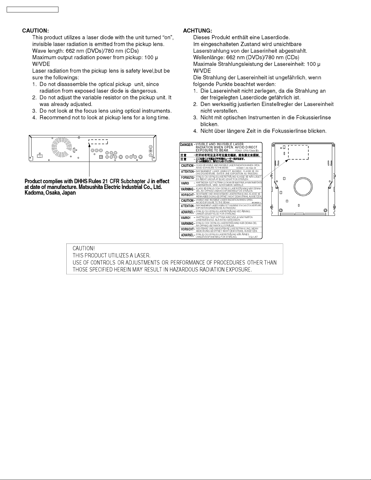
2.2. Precaution of Laser Diode
6
DMR-ES45VP / DMR-ES46VP
2.3. Service caution based on legal restrictions
2.3.1. General description about Lead Free Solder (PbF)
The lead free solder has been used in the mounting process of all electrical components on the printed circuit boards used for this
equipment in considering the globally environmental conservation.
The normal solder is the alloy of tin (Sn) and lead (Pb). On the other hand, the lead free solder is the alloy mainly consists of tin
(Sn), silver (Ag) and Copper (Cu), and the melting point of the lead free solder is higher approx.30 degrees C (86°F) more than that
of the normal solder.
Definition of PCB Lead Free Solder being used
The letter of “PbF” is printed either foil side or components side on the PCB using the lead free solder.
(See right figure)
Service caution for repair work using Lead Free Solder (PbF)
· The lead free solder has to be used when repairing the equipment for which the lead free solder is used.
(Definition: The letter of “PbF” is printed on the PCB using the lead free solder.)
· To put lead free solder, it should be well molten and mixed with the original lead free solder.
· Remove the remaining lead free solder on the PCB cleanly for soldering of the new IC.
· Since the melting point of the lead free solder is higher than that of the normal lead solder, it takes the longer time to melt
the lead free solder.
· Use the soldering iron (more than 70W) equipped with the temperature control after setting the temperature at 350±30
degrees C (662±86°F).
Recommended Lead Free Solder (Service Parts Route.)
· The following 3 types of lead free solder are available through the service parts route.
RFKZ03D01K-----------(0.3mm 100g Reel)
RFKZ06D01K-----------(0.6mm 100g Reel)
RFKZ10D01K-----------(1.0mm 100g Reel)
Note
* Ingredient: tin (Sn), 96.5%, silver (Ag) 3.0%, Copper (Cu) 0.5%, Cobalt (Co) / Germanium (Ge) 0.1 to 0.3%
7
DMR-ES45VP / DMR-ES46VP
3 Service Navigation
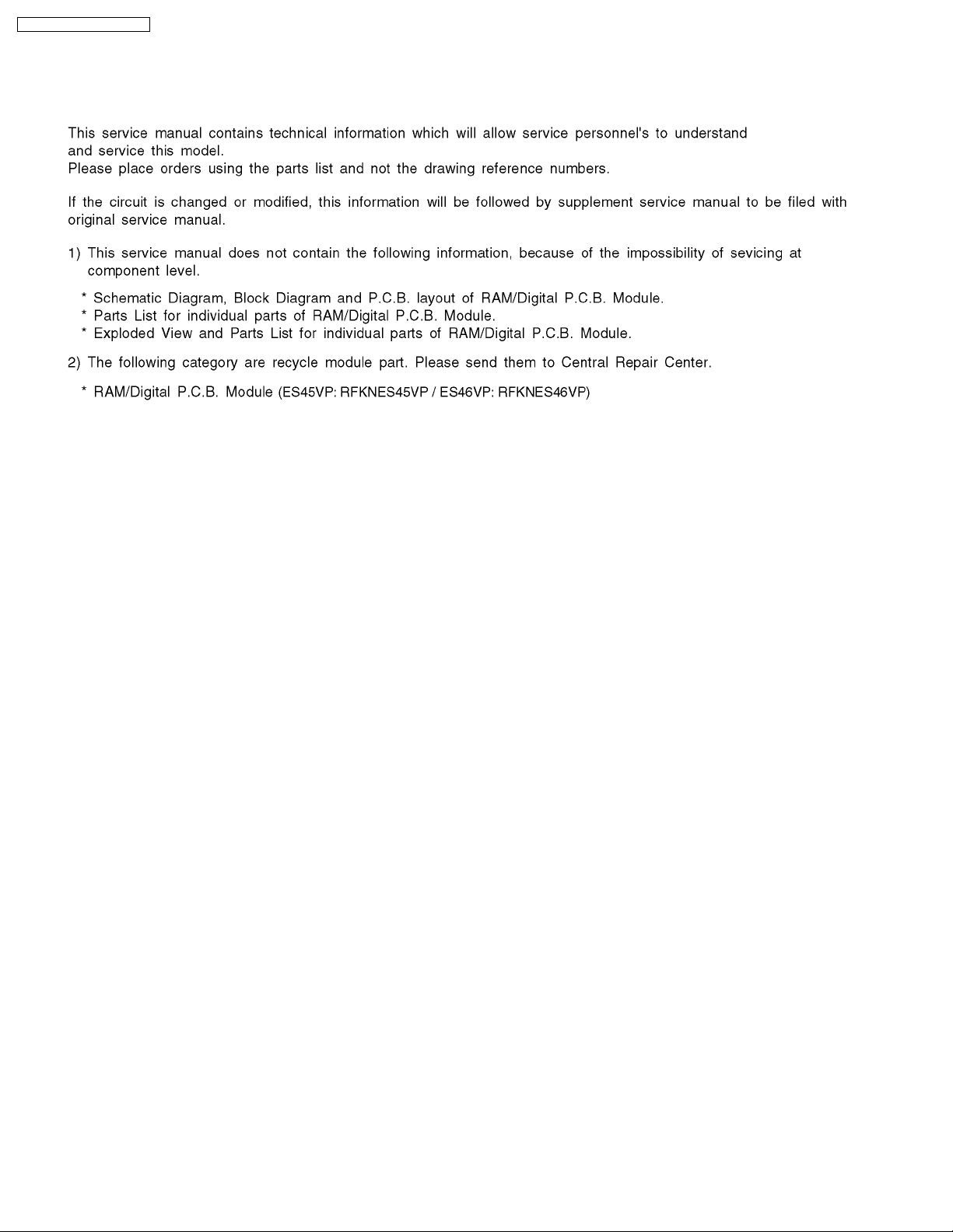
3.1. Service Information
8
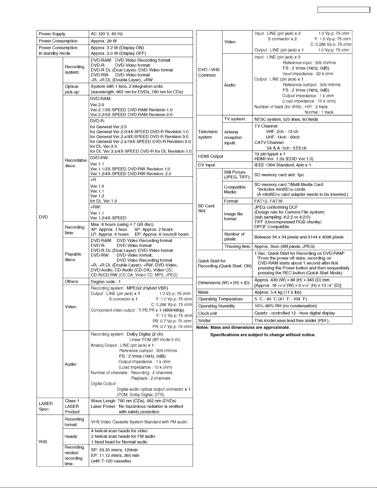
4 Specifications
DMR-ES45VP / DMR-ES46VP
9
DMR-ES45VP / DMR-ES46VP
5 Features
5.1. HDAVI Control (HDMI Link)
Linked operations by HDAVI Control (HDMI Link)
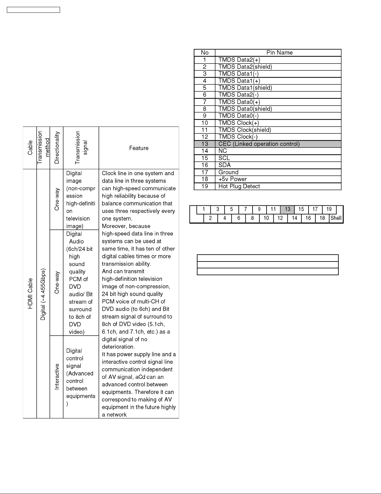
5.1.1. What is HDMI
HDMI is abbreviation of [High-Definition Multimedia Interface],
and is digital interface standard for next generation TV
corresponding to follows.
1. Non-compressing high quality digital image
2. Digital transmission of multi channel digital audio.
3. Two way communication of control signal of control
straightening between equipments
Pin Name
Pin layout of plug of HDMI cable seen from outside.
5.1.2. Link functions with Equipments
Corresponding Table
Functions
(1) Automatic Input switch
(2) Link of Power
In case setting of [FUNCTIONS] ® [Setup] ® [TV Screen] ®
[Functions of HDMI] ® [Control with HDMI] are on, all above
equipments Link functions are effective.
5.1.3. Outline of Equipments Linked
functions
(1) Automatic Input switch
At starting of playback/ GUI display by DIGA, it turns on
power of VIErA, and it displays picture of DIGA onto screen
of VIErA.
Starting of playback:
It includes automatic playback of DVD-Video and so on.
And it includes picture of screen saver too.
GUI display:
FUNCTIONS, DIRECT NAVIGATOR, TV PROGRAM,
PROG/CHECK, Timer Recording, G-code, Initial setting,
Playback setting, Play list, SD/DVD guide, Warning
messages that user can select and so on.
10
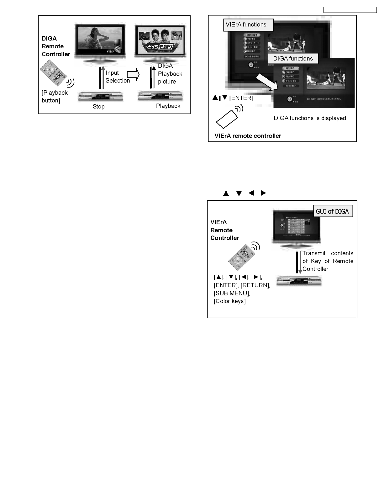
(2) Seamless GUI
1. Automatic switching to DIGA functions from VIErA
functions
When [operate DIGA] of VIErA functions is selected,
input of VIErA is switched to DIGA input automatically
and it displays DIGA functions.
2. Automatic switching to VIErA operation menu from
DIGA operation menu
It is function that DIGA operation menu is switched off
and VIErA operation menu is switched on when
[RETURN] button of VIErA remote controller is pressed
while first stage of DIGA operation menu is being
displayed,
3. Automatic switch off of GUI display of DIGA when
VIErA input selection/ VIErA operation menu is
displayed
GUI of DIGA is turned off when VIErA input selection is
performed while GUI of DIGA is being displayed.And
GUI of DIGA is turned off and VIErA operation menu is
displayed when VIErA operation menu is displayed
while GUI of DIGA is being displayed.
GUI Display:
Erasable GUI displays above are limited to screen that
are erasable by RETURN button in DIRECT
NAVIGATOR/ TV GUIDE/ FUNCTIONS/ PROGRAM
CHECK/ INITIAL SETTING.
However GUI displays that are not erasable by
RETURN button in FORMAT process/ ERASE process/
DUBBING process/ FINALIZE process/ CUTION
displayed are kept displaying.
DMR-ES45VP / DMR-ES46VP
(3) Remote Control Operation
Function that operate DIGA by VIErA remote controller
when DIGA screen is displayed on VIErA,
· Buttons of Remote Controller that can be operate by
VIErA remote controller:
, , , , ENTER, RETURN, SUB MENU
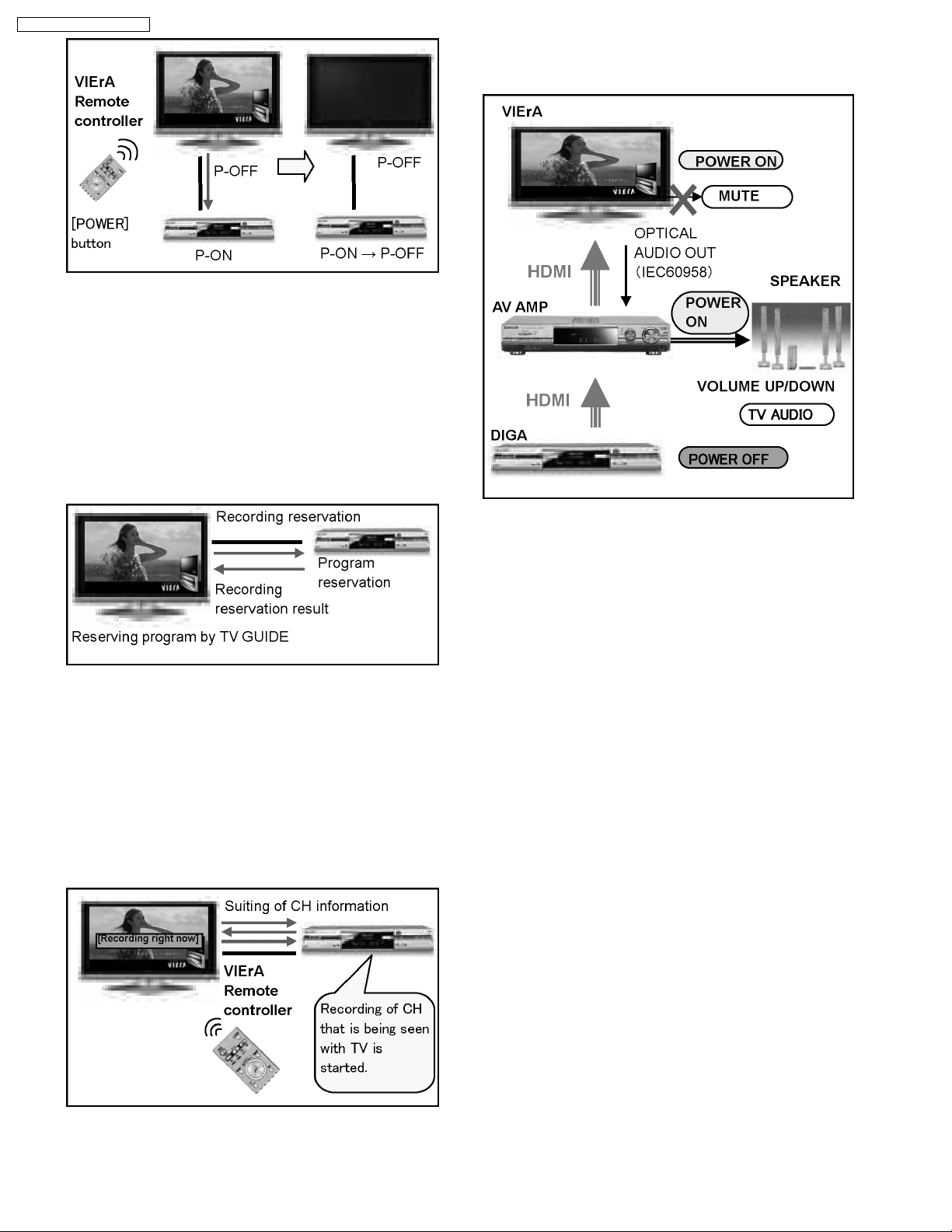
(4) Power Link
Power of DIGA is turned off linking to POWER OFF of
VIErA.
· Power of DIGA is not turned on linking to POWER ON
of VIErA.
· It is limited in following cases that DIGA links to POWER
OFF of VIErA.
1. During EE display (While Timer recording is being
executed/ Functions is being displayed are included.)
2. Case that DIGA is playing back (only North America/
Japan)
However except cases below.
· During EE display, but manual recording is being
executing/ during EXT_Link recording.
· During Tray is being opened.
· Case that DIGA is in status that power cannot turn off
(during dubbing, during finalize).
11
DMR-ES45VP / DMR-ES46VP
(5) Timer Recording (Reservation Recording)
When select [Reserve] of TV GUIDE of VIErA, Reservation
information is transmitted by way of HDMI (HDAVI Control),
and reservation registration of DIGA is done.
· In DIGA, it treats as well as a usual program reservation
and Timer Recording reservation.
· Linking reservation from VIErA is not done.
· Recordable media is fixed to HDD
· Recording mode of digital program is fixed to DR and
recording mode of analog program is fixed to SP mode.
pressed, VIErA POWER ON/ Input switch/ audio mute is set
automatically, and audio sound is output from speaker
connected amp.
(6) Recording right now
When [REC RIGHT NOW] is selected on GUI of VIErA, CH
that is being seen is recorded by DIGA.And when [STOP
RIGHT NOW] is selected on GUI of VIErA, recording of
DIGA is stopped.
· Function of [recording right now] is based on manual
recording of DIGA. But recordable media is fixed to
HDD.
Recording mode is same as latest mode, similarly to
manual recording.
(7) Link with Amp
In system including DIGA, VIErA, Amplifier or Theater,
when [ONE TOUCH THEATER PLAYBACK] button was
12
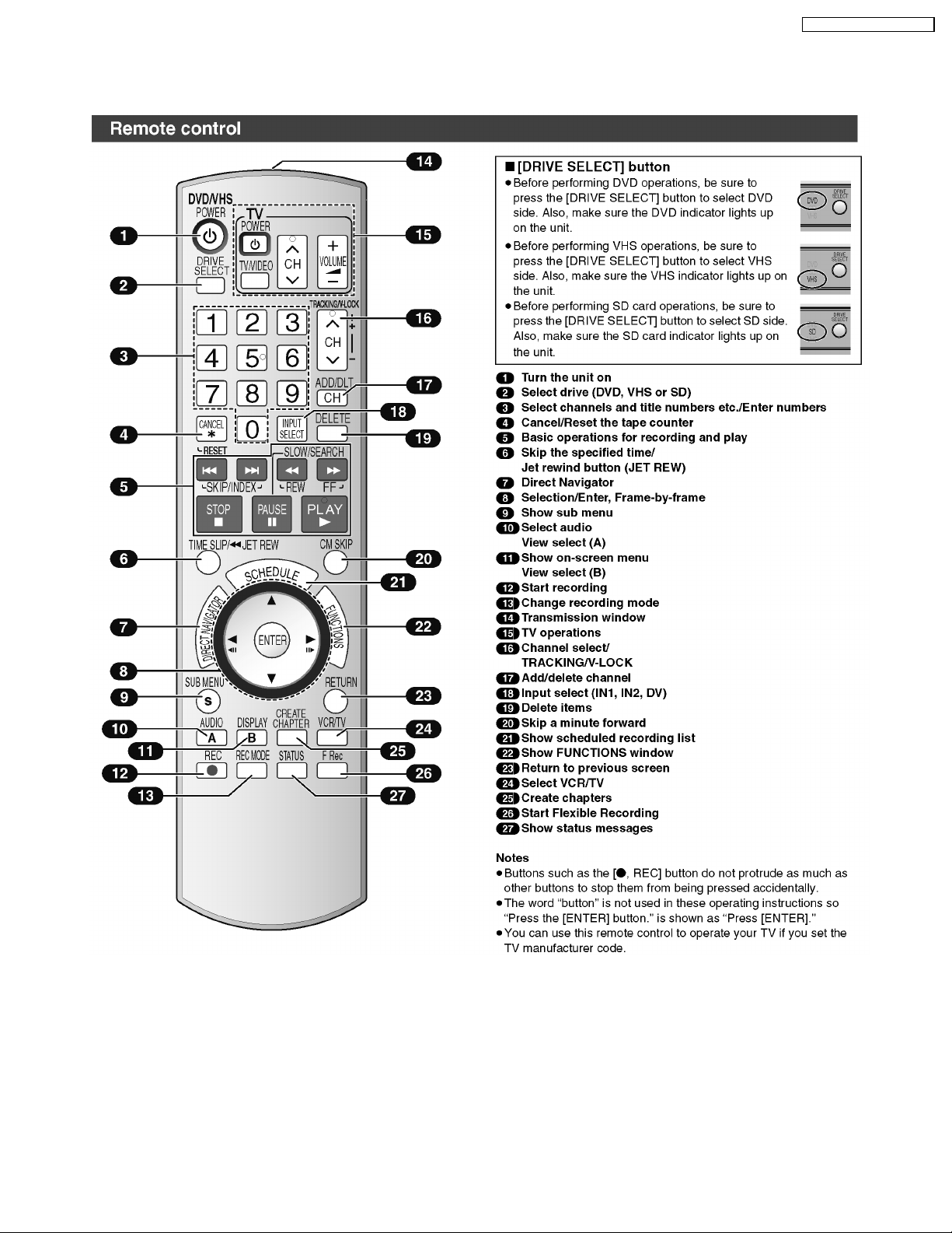
6 Location of Controls and Components
6.1. Each Buttons
DMR-ES45VP / DMR-ES46VP
13
DMR-ES45VP / DMR-ES46VP
14
DMR-ES45VP / DMR-ES46VP
7 Operation Instructions
7.1. (DVD) Taking out the Disc from RAM-Drive Unit when the Disc cannot
be ejected by OPEN/CLOSE button
7.1.1. (DVD) Forcible Disc Eject
7.1.1.1. (DVD) When the power can be turned off.
1. Turn off the power and press [STOP], [CH UP] keys on the front panel simultaneously for 5 seconds.
7.1.1.2. (DVD) When the power can not be turned off.
1. Press [POWER] key on the front panel for over 10 seconds to turn off the power forcibly, and press [STOP] [CH UP] keys on
the front panel simultaneously for 5 seconds.
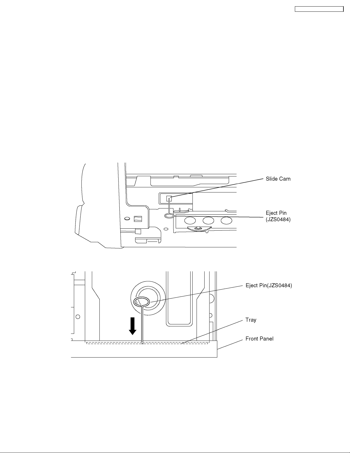
7.1.2. (DVD) When the Forcible Disc Eject can not be done.
1. Turn off the power and pull out AC cord.
2. Remove the Top Case.
3. Push in SLIDE CAM by Eject Pin(JSJ0484) or minus screw driver (small) to eject tray slightly.
4. Push out Tray by Eject Pin (JZS0484) or minus screw driver (small).
15
DMR-ES45VP / DMR-ES46VP
7.2. (VHS) Removing Cassette
Tape manually
When the cassette tape could not be uninstalled from an
electrical malfunction, there are 2 ways to remove a cassette
tape.
7.2.1. (VHS) Removal by compulsory
unloading.
If Service Mode can be activated when the power can not be
turned on, this operation is able.
1. Press [STOP] and [EJECT] button simultaneously for more
than 3 seconds and set the Service Mode to 7.
2. Press [STOP] button in order to unload the mechanism.
(Pay attention to tape slack)
Service Mode Display:
7****(STOP)® 70L**(EJECT)
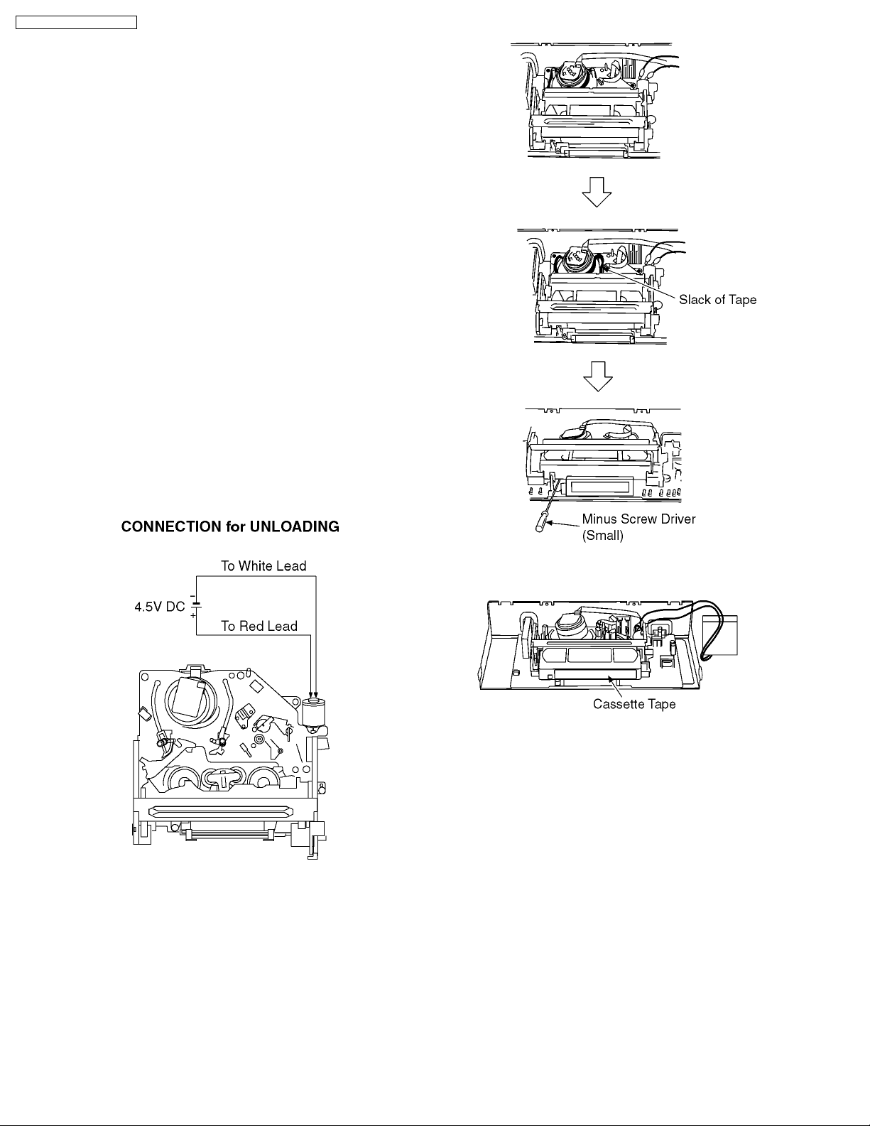
7.2.2. (VHS) Removal by manual
operation by rotating the Loading
Motor with the batteries.
1. Disconnect the AC plug, and remove the Top Panel and the
Front Panel by referring to the Disassembly Procedures.
2. Connect three batteries (1.5V spec.) to the Loading Motor
in series for supplying 4.5V to rotate the Loading Motor as
shown below.
3. Stop unloading just before unloading will be completed as
shown below, and then the tape becomes slack as shown
below.
4. Rotate the S-Reel by a small minus screwdriver to remove
the slack tape as shown below.
5. Then unload again to remove the cassette tape as shown
below.
7.2.3. (VHS) Take out Cassette
Tapemanually after removing the
mechanism
1. Disconnect the AC plug, and remove the Top Case, Front
Panel and the Mechanism by referring to "10 Assembling
and Disassembling"
2. Remove the Screw and remove the Loading Motor as
shown below.
16
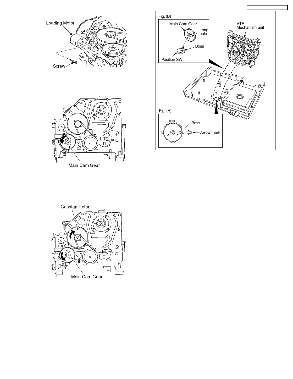
3. Rotate the Main Cam Gear counter-clockwise until just
before the unloading will be completed as shown below. .
DMR-ES45VP / DMR-ES46VP
4. Rotate the Capstan Motor clockwise to remove the slack
tape as shown below.
5. Rotate the Main Cam Gear counter-clockwise again to
remove the cassette-tape as shown below.
6. Attach Loading Motor and tighten the screw.
7. Set the Position Switch to EJECT POSITION certainly and
attach the mechanism to chassis as shown below.
17
DMR-ES45VP / DMR-ES46VP
8 Service Mode
8.1. (DVD) Self-Diagnosis and Special Mode Setting
8.1.1. (DVD) Self-Diagnosis Functions
Self-Diagnosis Function provides information for errors to service personnel by “Self-Diagnosis Display” when any error has
occurred.
U**, H** and F** are stored in memory and held.
You can check latest error code by transmitting [0] [1] of Remote Controller in Service Mode.
Automatic Display on FL will be cancelled when the power is turned off or AC input is turned off during self-diagnosis display is ON.
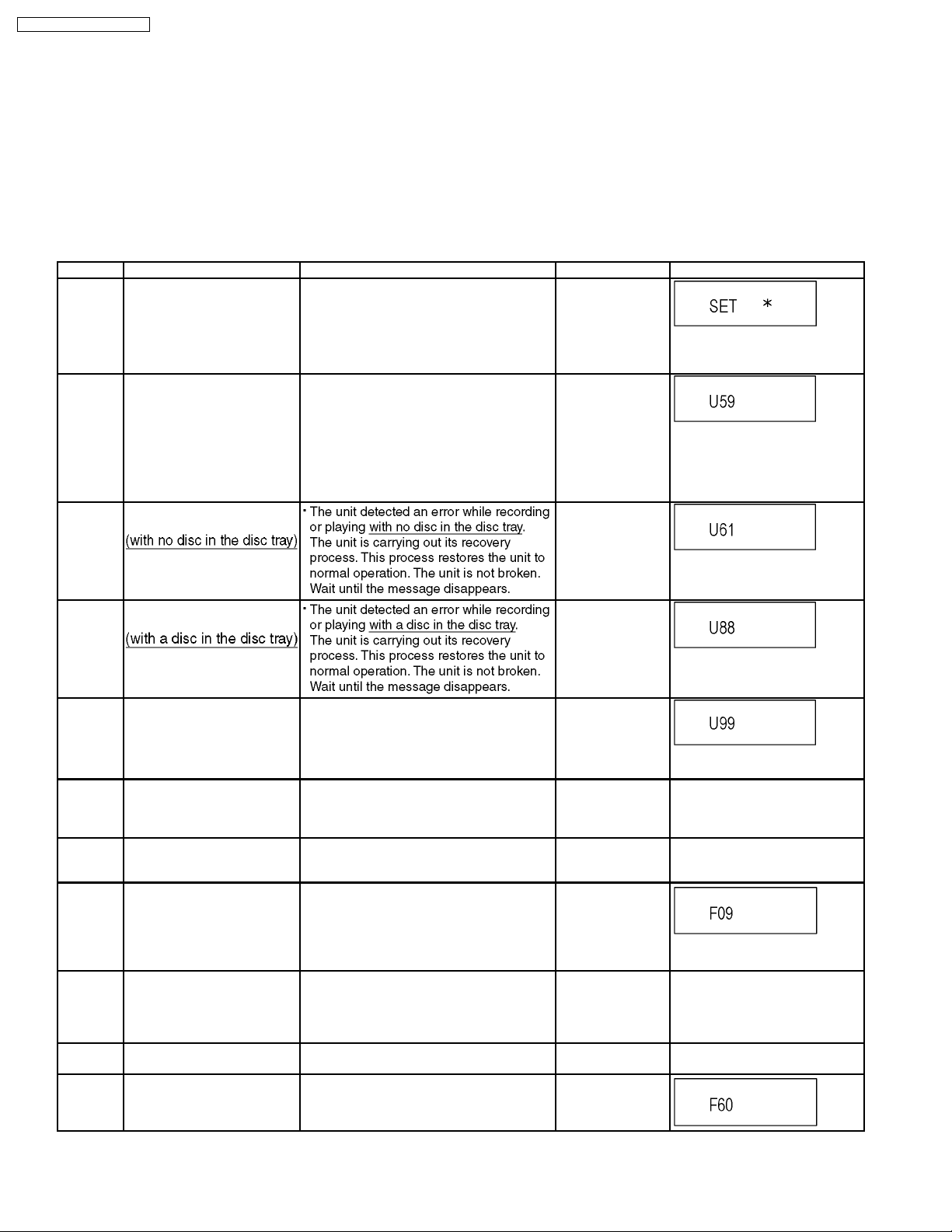
Error Code Diagnosis contents Description Monitor Display Automatic FL display
U30 Remote control code error Display appears when main unit and remote
U59 Abnormal inner temperature
detected
U61 The unit is carrying out its
recovery process.
controller codes are not matched.
Display appears when the drive temperature
exceeds 70°C.
The power is turned off forcibly.
For 30 minutes after this, all key entries are
disabled. (Fan motor operates at the highest
speed for the first 5 minutes. For the
remaining 25 minutes, fan motor is also
stopped.) The event is saved in memory as
well.
No display
“*” is remote controller code of the
main unit.
Display for 5 seconds.
No display
“U59 is displayed for 30 minutes.
No display
U88 The unit is carrying out its
U99 Hang-up Displayed when communication error has
H19 Inoperative fan motor When inoperative fan motor is detected after
F00 No error information Initial setting for error code in memory
F09 Serial Communication Error
F34 Initialization error when main
F58 Drive hardware error When drive unit error is detected, the event is
F60 DVD module has not been
recovery process.
between VHS Microprocessor
and Timer Microprocessor.
microprocessor is started up
for program recording
started.
occurred between Main microprocessor and
Timer microprocessor.
powered on, the power is turned off
automatically.
The event is saved in memory.
(Error code Initialization is possible with error
code initialization and main unit initialization.)
Please confirm Serial Communication
terminal of Microprocessor.
NOTE:
If F09 appears just after updating Firmware,
pull off and insert AC plug, then it will
disappear.
When initialization error is detected after
starting up main microprocessor for program
recording, the power is turned off
automatically.
The event is saved in memory.
saved in memory.
Defect of Digital P.C.B.
Mode: No change
No display
No display
Displayed is left until the
[POWER] key is pressed.
No display No display
No display No display
No display
No display No display
No display No display
No display
18
DMR-ES45VP / DMR-ES46VP
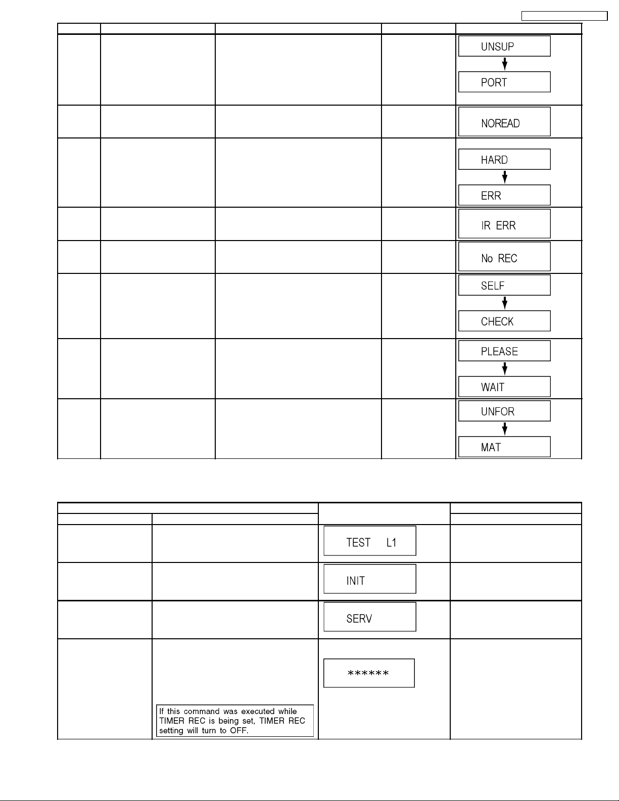
Error Code Diagnosis contents Description Monitor Display Automatic FL display
UNSUPPORTUnsupported disc error *An unsupported format disc was played,
NO READ Disc read error *A disc is flawed or dirty.
HARD
ERR
Drive error The drive detected a hard error. “DVD drive error.” Display for 5 seconds.
although the drive starts normally.
*The data format is not supported, although
the media type is supported.
*Exceptionally in case of the disc is dirty.
*A poor quality failed to start.
*The track information could not be read.
“This disc is
incompatible.”
Display for 5 seconds.
“Cannot read.
Please check the
disc.”
IR ERR IR communication error [IR ERR] is displayed when communication
No REC Recording is impossible [No REC] is displayed when recording is
SELF
CHECK
PLEASE
WAIT
UNFORMATUnformatted disc error You have inserted an unformatted DVD-RAM
Restoration operation Since the power cord fell out during a power
Unit is in termination process Unit is in termination process now.
between Timer microprocessor and IR
microprocessor fails.
impossible due to the defect, dirt or wound of
media.
failure or operation, it is under restoration
operation.
*It will OK, if a display disappears
automatically. If a display does not disappear,
there is the possibility that defective Digital
P.C.B. / RAM drive.
“BYE” is displayed and power will be turned
off.
In case “Quick Start” of setup menu is ON, it
is displayed in restoration operation for AC
off.
or DVD-RW that is unformatted or recorded
on other equipment.
8.1.2. (DVD) Special Modes Setting
No display
No display
No display
No display
Item FL display Key operation
Mode name Description Front Key
TEST Mode *All the main unit´s parameters (include tuner)
are initialized.
Rating password The audiovisual level setting password is
initialized to “Level 8”.
Service Mode Setting every kind of modes for servicing.
*Details are described in “8.1.3. (DVD)
Service Modes at a glance”.
Forced disc eject Removing a disc that cannot be ejected.
The tray will open and unit will shift to P-off
mode.
*When Timer REC is ON, execute " Forced
disc eject " after releasing Timer REC.
While Demonstration Lock is being set, this
Forced disc eject function is not accepted.
The display before execution
leaves.
Press [VHS to DVD DUBBING],
[REC] and [OPEN/CLOSE] keys
simultaneously for five seconds
when power is off.
Set DRIVE SELECT to [DVD].
While the tray is open, press [REC]
and [PLAY] simultaneously for 5
seconds.
When the power is off, press [VHS
to DVD DUBBING], [OPEN/CLOSE]
and [STOP] keys simultaneously for
5 seconds.
When the power is off, press
[STOP] and [CH UP] keys
simultaneously for 5 seconds.
19
DMR-ES45VP / DMR-ES46VP
Item FL display Key operation
Mode name Description Front Key
Forced power-off When the power button is not effective while
power is ON, turn off the power forcibly.
*When Timer REC is ON, execute “Forced
Power-off” after releasing Timer REC.
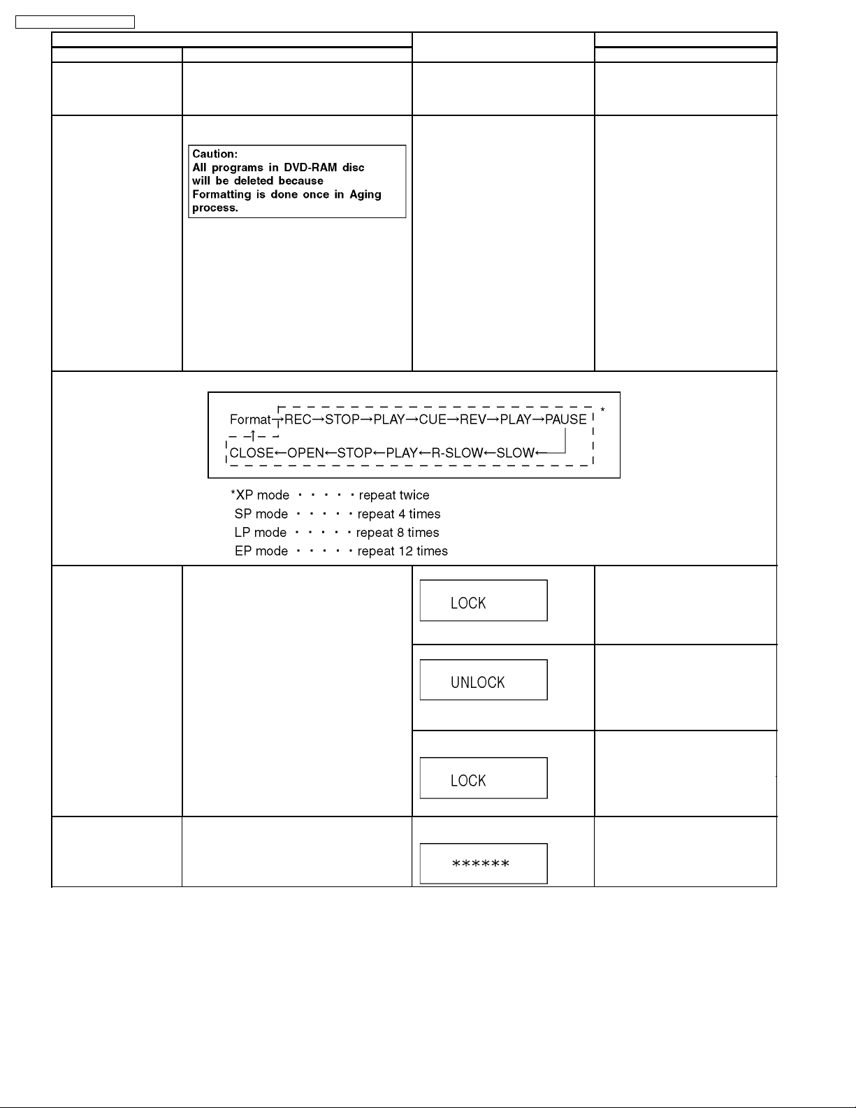
Aging Perform sequence of modes as * Aging
Description shown below continually.
Display in P-off mode. Press [POWER] key over than 10
seconds.
Display following the then mode. When the power is ON, press [CH
DOWN], [VHS to DVD DUBBING]
and [OPEN/CLOSE] simultaneously
for over 5 seconds and less than 10
seconds.
NOTE1:
If Unit has not turned into Aging
mode by operations shown above,
execute TEST MODE once and reexecute operation shown above.
(*All the main unit’s parameters
include tuner are initialized by TEST
mode.)
NOTE2:
If the unit has hung-up because of
pressing keys for over 10 seconds,
once turn off the power, and reexecute this command.
*When releasing Aging mode, press
[POWER] key.
Aging Contents (Example):
Demonstration
lock/unlock
Progressive initialization The progressive setting is initialized to
Ejection of the disc is prohibited.
The lock setting is effective until unlocking the
tray and not released by “Main unit
initialization” of service mode.
Interlace.
*When lock the tray.
“LOCK” is displayed for 3 seconds.
*When unlock the tray.
“UNLOCK” is displayed for 3
seconds.
*When press OPEN/CLOSE key
while the tray being locked.
Display “LOCK” for 3 seconds.
The display before execution
leaves.
When the power is on, press
[STOP] and [POWER] keys
simultaneously for 5 seconds.
Note:
When a disc is not in tray, this
setting is not effective.
When the power is on, press
[STOP] and [POWER] keys
simultaneously for 5 seconds.
Press [OPEN/CLOSE] key while the
tray being locked.
When the power is on (E-E mode),
press [STOP] and [VHS to DVD
DUBBING] simultaneously for 5
seconds.
20
DMR-ES45VP / DMR-ES46VP
8.1.3. (DVD) Service Modes at a glance
Service mode setting: While the power is off, press [STOP], [VHS to D VD DUBBING] and [OPEN / CLOSE] simultaneously for
five seconds (OPERATION SELECT should be set to DVD).
Item FL display Key operation
Mode name Description (Remote controller key)
Release Items Item of Service Mode executing is cancelled. Press [0] [0] or [Return] in service
mode.
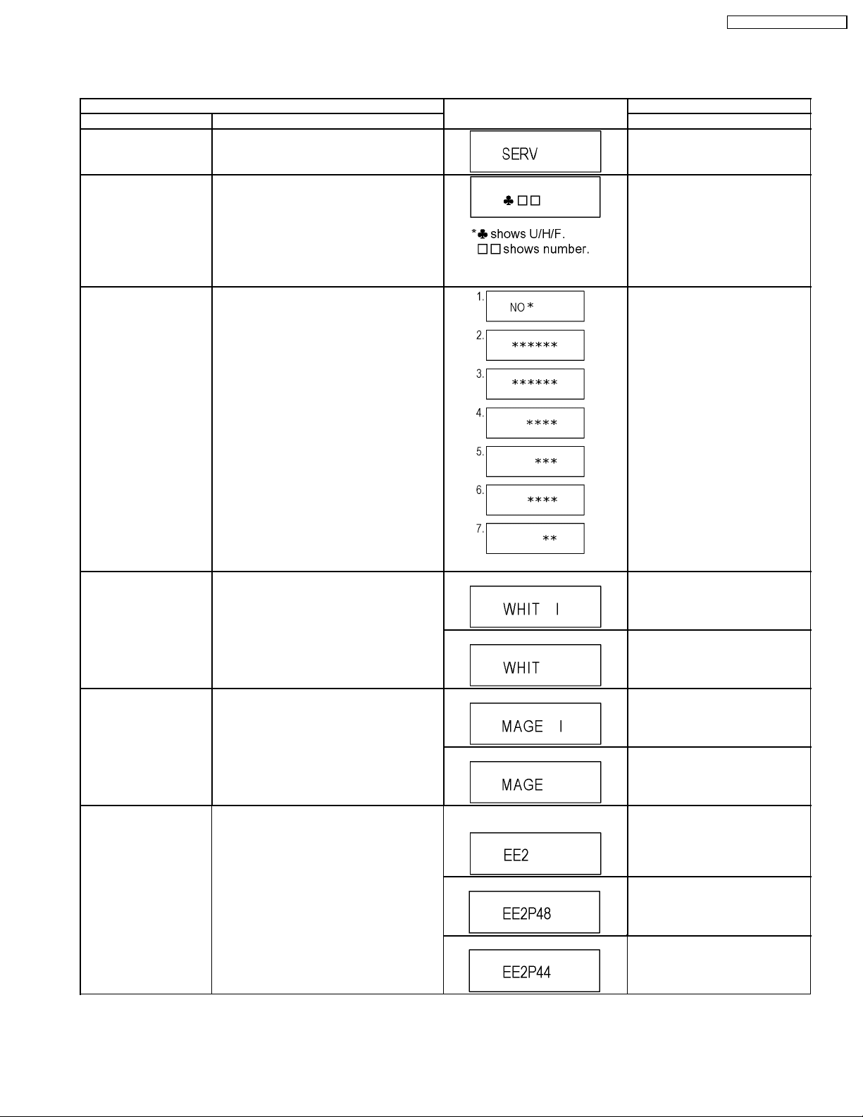
Error Code Display Last Error Code of U/H/F held by Timer is
displayed on FL.
*Details are described in “8.1.1. (DVD) Self-
Diagnosis Functions”.
ROM Version Display 1. Region code (displayed for 5 sec.)
2. Main firm version (displayed for 5 sec.)
3. Timer firm version (displayed for 5 sec.)
4. Drive firm version (displayed for 5 sec.)
5. ROM correction version
(displayed for 5 sec.)
6. VHS Microprocessor version
(displayed for 5 sec.)
7. VHS ROM correction version
(left displated)
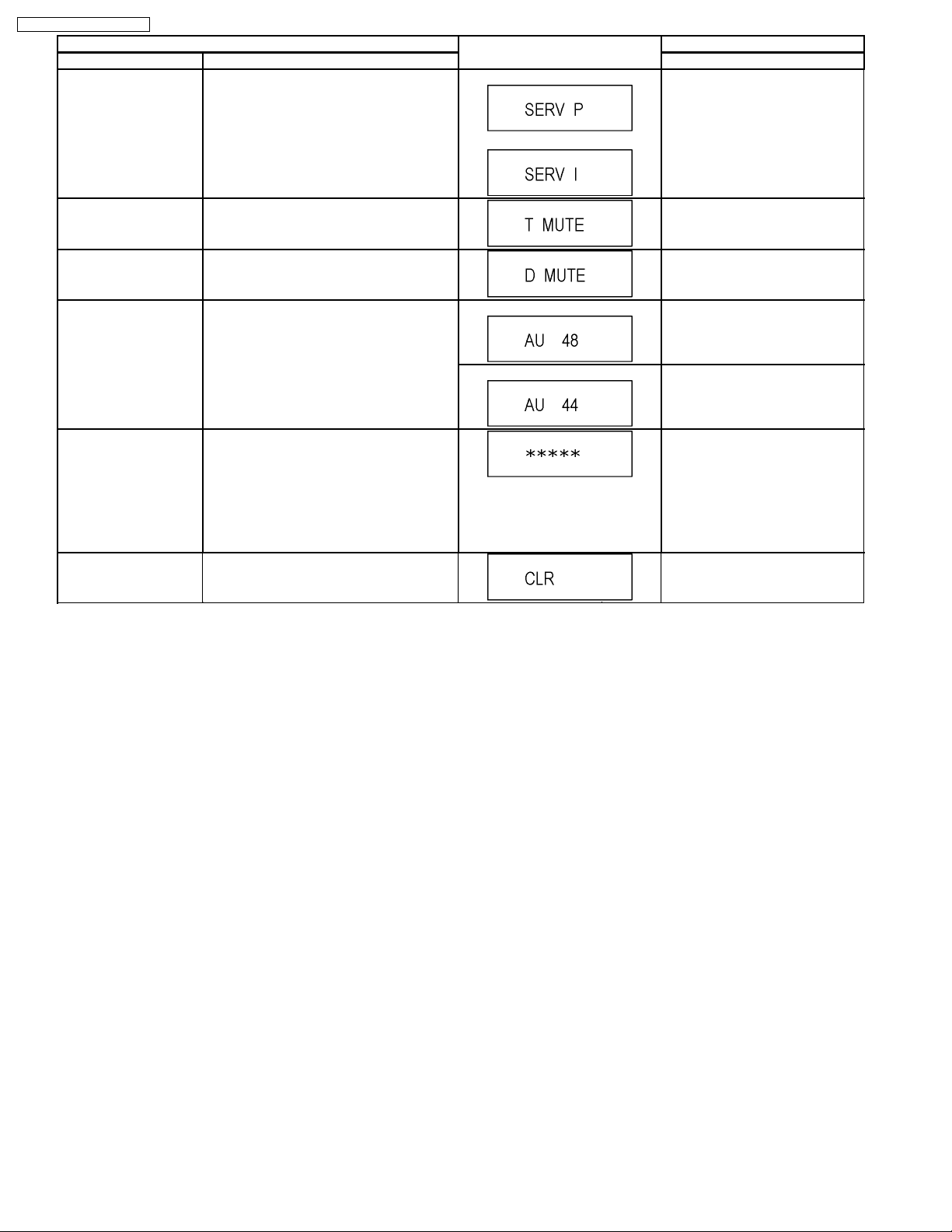
White Picture Output White picture is output as component Output
from AV Decoder.
*White picture
(Saturation rate : 100%)
*It is enable to switch Interlace/Progressive by
“I/P switch: [1] [4]”
Press [0] [1] in service mode
If any error history dose not exist,
[F00] is displayed.
Press [0] [2] in service mode
‘’*’’ are version displays.
*Initial mode is “Interlace”. Press [1] [1] in service mode.
Switch Interlace/Progressive Press [1] [4] in White Picture Output
mode.
*I/P are switched alternately.
Magenta Picture Output Magenta picture is output with Component
RTSC Return in XP
(A&V)
Output from AV Decoder.
*Magenta picture
(Saturation rate: 100%)
*It is enable to switch Interlace/Progressive by
“I/P switch: [1] [4]”
L1 input signal is encoded (XP), decoded
(XP) and output decoded signal to external
without DISC recording and DISC playback.
*Initial mode is “Interlace”. Press [1] [2] in service mode.
Switch Interlace/Progressive Press [1] [4] in Magenta Picture
Initial mode: EE2/ Interlace/ XP/
Audio 48kHz
Switch Interlace/Progressive Press [1] [4] in RTSC Return XP
Audio 44.1 kHz/ 48 kHz Switch Press [2] [4] in RTSC Return XP
Output mode.
*I/P are switched alternately.
Press [1] [3] in service mode.
mode.
*I/P are switched alternately.
mode.
*48 kHz / 44.1 kHz are switched
alternately.
21
DMR-ES45VP / DMR-ES46VP
Item FL display Key operation
Mode name Description (Remote controller key)
I/P Switch Switch Interlace and Progressive in EE mode.
*Initial setting is “Interlace”.
*This command is effective during executing
“White Picture Output”, “Magenta Picture
Output” and “RTSC Return in XP (A & V)”
modes.
Initial mode is Interlace
Switch Interlace/Progressive
Press [1] [4] in I/P Switch mode.
*I/P are switched alternately.
Audio Mute (XTMUTE) Check whether mute is applied normally by
the timer microprocessor.
Audio Mute (XDMUTE) Check whether mute is applied normally by
the Digital P.C.B..
Audio Pattern Output The audio pattern stored in the internal
memory is output
(Lch: 1kHz/-18dB)
(Rch: 400Hz/-18dB)
*Audio sound clock switching operation of
DAC can be confirmed by sub command [2]
[4].
Laser Used Time
Check laser used time (hours) of drive.
Indiction
Delete the Laser Used
Time
Laser used time stored in the memory of the
unit is deleted.
Press [2] [1] in service mode.
Press [2] [2] in service mode.
Initial mode (Audio 48kHz) Press [2] [3] in service mode.
Audio 44.1kHz/48kHz switching Press [2] [4] in Audio Pattern Output
mode.
*48 kHz / 44.1 kHz are switched
alternately.
Press [4] [1] in service mode.
l(*****) is the used time display in
hour.
lLaser used time of DVD/ CD in
Playback/Recording mode is
counted.
Press [9] [5] in service mode.
22
Item FL display Key operation
Mode name Description (Remote controller key)
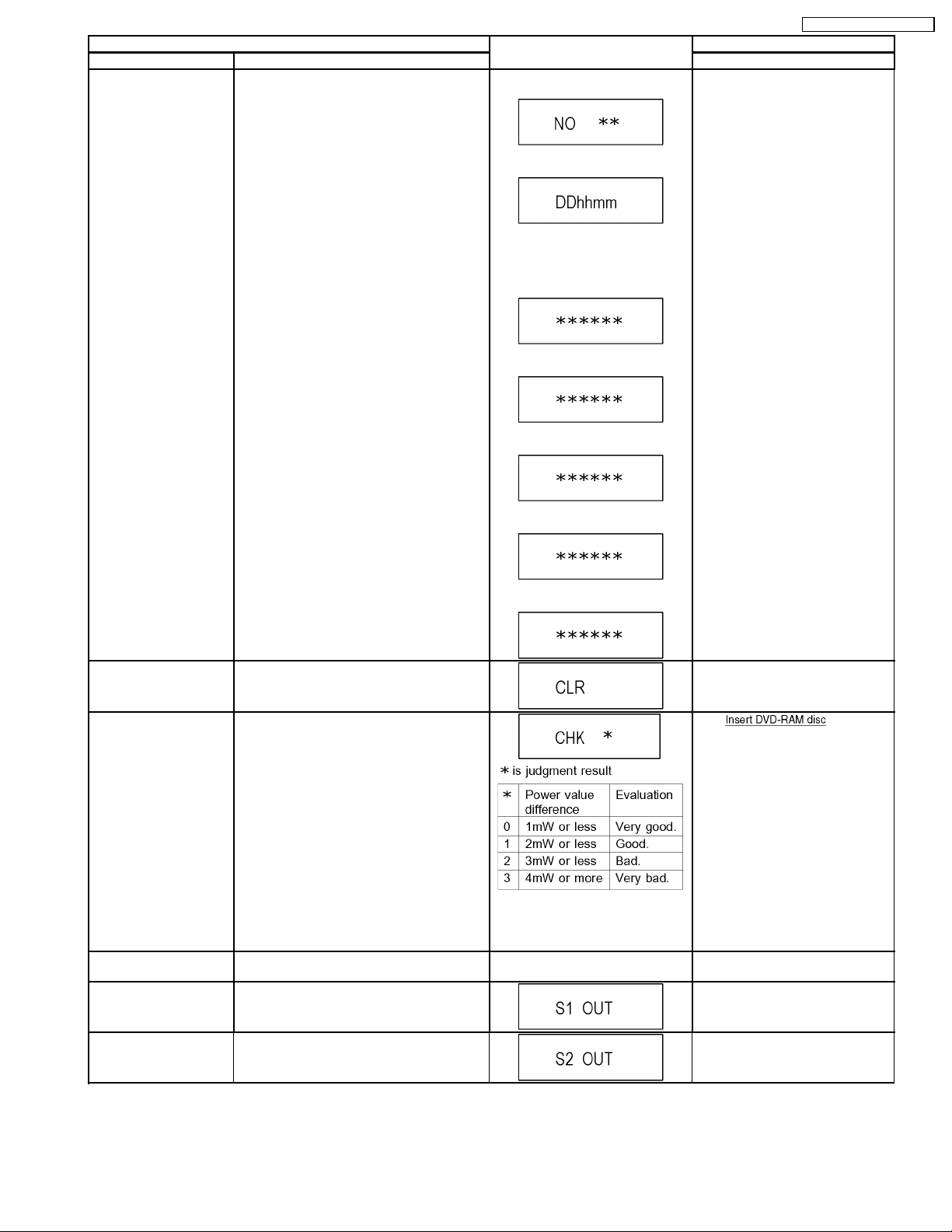
RAM Drive Last Error RAM Drive error code display.
*For details about the drive error code, refer
to the Service Manual for the specific RAM
Drive.
1. Error Number is displayed for 5
seconds.
Press [4] [2] in service mode.
When “INFO******” is being
displayed, past 19 error histories
can be displayed by pressing [0] [1]
-[1][9]
2. Time when the error has occurred
is displayed for 5 seconds.
DD: Day
hh: Hour
mm: Minute
3. Last Drive Error (1/2) is displayed
for 5 seconds.
4. Last Drive Error (2/2) is displayed
for 5 seconds.
5. Error occurring Disc type is
displayed for 5 seconds.
DMR-ES45VP / DMR-ES46VP
Delete the Last Drive
Error
Delete the Last Drive Error information stored
on the DVD RAM-Drive.
Laser power confirmation Drive state is judged based on difference
between laser power value at shipping and
present laser power value.
Turn on all FL/LEDs All segments of FL and all LEDs are turned
on.
S1 signal output Forcibly superimpose the S1 signal (approx.
4.5V DC) on the EE chroma signal, and check
the output on the S terminal.
S2 signal output Forcibly superimpose the S2 signal (approx.
2V DC) on the EE chroma signal, and check
the output on the S terminal.
6. Disc Maker ID is displayed for 5
seconds.
In case that the maker cannot be
identified, display is black out.
7. Factor of Drive Error occurring is
left displayed
Press [9] [6] in service mode.
1. into RAM
Drive in service mode. (Other
media are assumed to be noncorrespondence.)
2. Press [4] [4].
If DVD-RAM disc in not inserted,
[NO DISC] is displayed.
If power value study was filed,
[ERROR] is displayed.
All segments are turned on. Press [5] [1] in service mode.
Press [5] [2] in service mode.
Press [5] [3] in service mode.
23
DMR-ES45VP / DMR-ES46VP
Item FL display Key operation
Mode name Description (Remote controller key)
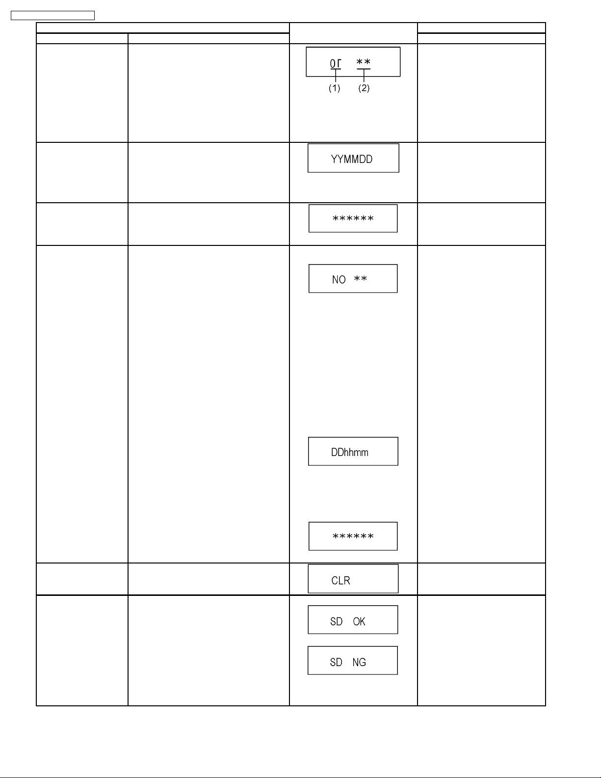
Front connection
inspection
Production Date Display Display the date when the unit was produced.
Display the accumlated
working time
Display the Error History Display the Error History stored on the unit. Display reason of error for 5
Press all front keys and check the connection
between Main P.C.B. and Front key Switches.
(1) Each time a key is pressed,
segment turned on increases one
by one.
(2) Total umber of keys that have
been pressed.
YY: Year
MM: Month
DD: Day
Display the accumulated unit´s working time.
(Indicating unit: Second)
seconds.
Press [5] [4] in service mode.
Press [6] [1] in service mode.
Press [6] [4] in service mode.
Press [6] [5] in service mode.
Then press [0] [1] ~ [1] [9], the past
19 error histories are displayed.
Delete the Error History Delete Error History information stored on the
unit.
01:
Defect of Digital P.C.B.
(AV DEC / MAIN CPU)
02:
Defect of RAM Drive.
03:
Defect of Disc.
04:
Defect of Digital P.C.B. or
Communication Error.
05:
Defect of Digital P.C.B.
(AV DEC / MAIN CPU)
Display the time when the error has
occurred for 5 seconds.
DD: Day
hh: Hour
mm: Minute
Accumulated working time till
occuring of the error is left
displayed.
(Indicating unit: Second)
Press [9] [7] in service mode.
SD card WRITE check Delete Error History information stored on the
unit.
When the WRITE check is OK.
When the WRITE check is NG.
*Note:
The image stored in the SD card will
be erased.
24
InsertaSDcardtoSDcardslot,
and press [7] [4] in service mode.
*Insert SD card while the power is
off.
*Check for [CARD SD] display on
the FL display and go on the
procedure.
Item FL display Key operation
Mode name Description (Remote controller key)
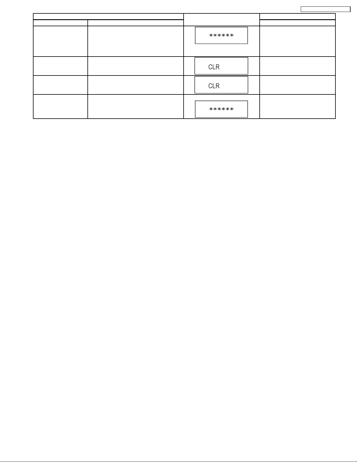
Tray OPEN/CLOSE Test The RAM drive tray is opened and closed
repeatedly.
Press [9] [1] in service mode
*When releasing this mode, press
the [POWER] button of Remote
“*” is number of open/close cycle
Controller more than 10 seconds.
times.
Error code initialization Initialization of the last error code held by
Press [9] [8] in service mode.
timer (Write in F00)
DMR-ES45VP / DMR-ES46VP
Initialize Service Last Drive Error, Error history and Error
Press [9] [9] in service mode.
Codes stored on the unit are initialized to
factory setting.
Finishing service mode Release Service Mode. Display in STOP (E-E) mode. Press power button on the front
panel or Remote controller in
service mode.
25
DMR-ES45VP / DMR-ES46VP
8.2. (VHS) Self-Diagnosis and Special Mode Setting
8.2.1. (VHS) Self-Diagnosis Functions
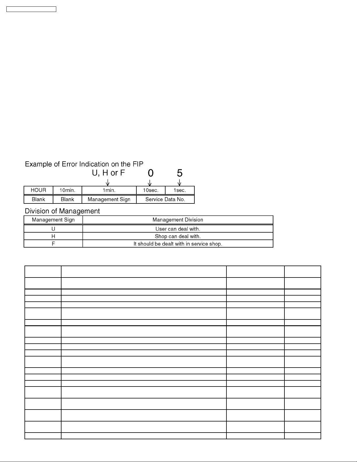
This model has a self-diagnosis and display function. If the VHS section detects trouble during installation or during use, one of the
following Error Codes will automatically appear in the display on VHS side. Error Codes are displayed in the form of a single English
letter followed by two numbers, as for example "H01".
Note:
1. The indication "U" is displayed on the FIP while power remains on.
2. The indication "H" or "F" is displayed on the FIP, and the power is automatically turned off. When the power is turned on
again, the Error indication code will disappear and the unit will return to normal display mode (either clock or counter is
displayed).
3. This Error indication code will be stored in the microprocessor even after the AC plug being disconnected.
The two-digit number portion of the stored Error indication code can be re-displayed in "second" display portion (the last 2
digits of the FIP) by placing the unit is Service Mode Number 3 When turning on Service Data Display as for example "01"
or "02" etc. If a second error occurs, the most recent error will be displayed and stored until 3 self-diagnosis histories in
maximum.
4. To erase the stored Error Code data, Press FF and EJECT buttons on VCR simultaneously for over 5 seconds in Service
Mode 3.
Error Number at a glance
Memory No.
(Error No.)
H01 The cylinder could not be started.
(Error of the cylinder or the cylinder driver.)
H02 The CAP FG could not be detected. Yes Yes
F03 Mechanism lock during without the unloading and the cassette-up. Yes Yes
F04 Mechanism lock during unloading Yes Yes
F05 S-reel pulse cannot be detected when a cassette tape is inserted.
(Error of the S-reel system or the Capstan system.)
F06 Mechanism lock during the Cassette-up. Yes Yes
F09 Communication Error between VHS Microprocessor (IC6001) and Timer
Microprocessor (IC7501)
H07 The recording circuit can not be operated in REC mode. Yes Yes
H08 The recording circuit is operated in except for REC mode. Yes Yes
U11 Cylinder clogs during the PLAY mode. Yes Yes
F15 S-reel pulse cannot be detected when a cassette tape is inserted.
(Error of the S-reel system or the Capstan system.)
H16 Detection of the Cylinder lock during the constant rotation No Yes
H17 Detection of S-reel lock during the constant tape running Yes Yes
H18 Detection of T-reel lock during the constant tape running Yes Yes
F20 NG1 in the PG Shifter Automatic Adjustment
(The cylinder rotation is unstable during the automatic adjustment.)
F21 NG2 in the PG Shifter Automatic Adjustment
(The vertical sync signal is lacked while over 5 seconds on the alignment tape.)
F22 NG3 in the PG Shifter Automatic Adjustment
(The installing position of Heads to the cylinder is our of specification.)
F23 NG4 in the PG Shifter Automatic Adjustment
(The servo is not locked to the cylinder for more than 10 sec.)
H80 An exceptional ejection depends on a Error No Yes
Reason Automatic display Memory
Yes Yes
No Yes
Yes Yes
No Yes
Yes Yes
Yes Yes
Yes Yes
Yes Yes
26
8.2.2. (VHS) Special Modes Setting
Item FL display Key operation
Mode name Description Front Key
Tracking Center Tape Tracking is adjusted to center
FIX position.
VHS Service Mode In order to make service easy, a part
of inside information of a
microprocessor is displayed on FIP.
*Details are described in "8.2.3.
(VHS) Service Modes ".
DMR-ES45VP / DMR-ES46VP
No display. During PLAYBACK, press [CH UP]
and [CH DOWN] keys
simultaneously.
Press [STOP], and [EJECT] keys
simultaneously for 3 seconds when
power is off.
Eject Ejecting Cassette Tape No display. While in other than Timer REC mode,
press [STOP] key for 3 seconds or
press [STOP] key of the Remote
Controller for 3 seconds in VHS
mode.
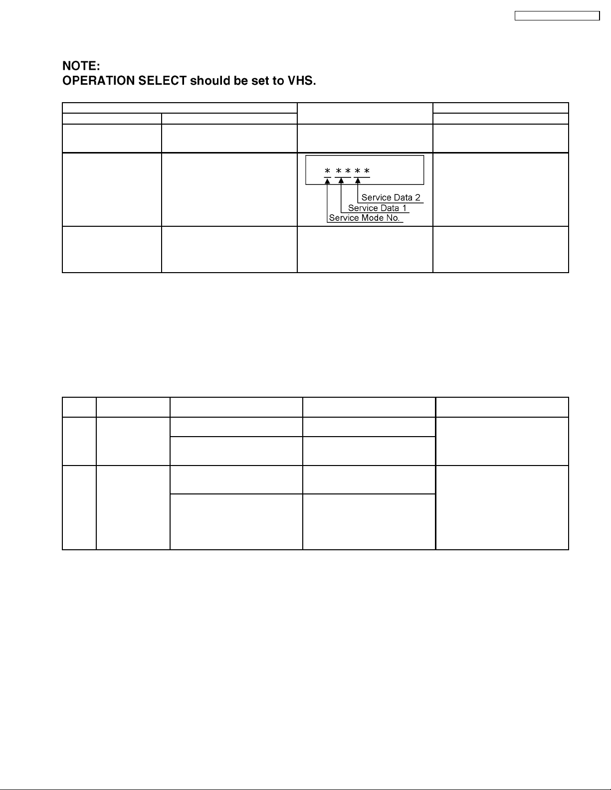
8.2.3. (VHS) Service Modes
<Service Mode Setting>
Set OPERATION SELECT to VHS.
When power is OFF, press [STOP] and [EJECT] keys simultaneously for 3 seconds to into Service Mode.
In Service Mode, press [STOP] and [EJECT] keys simultaneously to add Service Number.
8.2.3.1. (VHS) Service Mode and Service Data at a glance
Service
Number
0 Indication for the
1 Indication for the
Contents Contents of Indication on minute Contents of Indication on second Remarks
inner data of
IC6001
inner data of
IC6001
VHS mode
(Real time)
VCR mode
(OPM)
Starting / finishing edges detecting
data
(Real time)
00: Both starting / finishing edges
have not been
01: Starting edge is detecting now
02: Finishing edge is detecting now
03: Both starting / finishing edges
are detecting now
Process number
(Real time)
Management number of the
processing during mechanism
shifting
Data of receiving key (Real time)
Indicate the receiving code when the
key of VCR or remote controller
being operated.
27
DMR-ES45VP / DMR-ES46VP
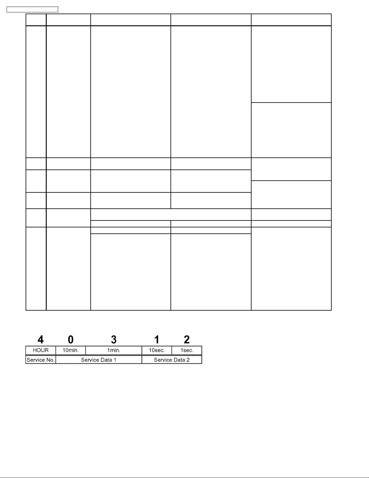
Service
Number
2 Indication for the
inner data of
IC6001
3 Self-diagnosis
history (1st)
4 Self-diagnosis
history (2nd)
5 Self-diagnosis
history (3rd)
6 Indication for the
inner data of
IC6001
7 Manual mechanism
operation
Contents Contents of Indication on minute Contents of Indication on second Remarks
Mechanism position
(Real time)
0L: EJECT position
02: DOWN position
03: RREW position
04: LOAD position
05: REV position
06: PLAY position
07: POFF position
08: STOP_R position
09: STOP_F position
- : FF/REW position
- : Intermediate between
each positions
Error number of history 1 Supplementary data 1 and 2 of
Error number of history 2 Supplementary data 1 and 2 of
Error number of history 3 Supplementary data 1 and 2 of
Real time servo data (4 digits)
(Real time)
Higher rank 1 BYTE of SERVO data Lower rank 1 BYTE of SERVO data
Real time mechanism position Real time ordering for the Motors Press the STOP key, and then the
0L: EJECT position
02: DOWN position
03: RREW position
04: LOAD position
05: REV position
06: PLAY position
07: POFF position
08: STOP_R position
09: STOP_F position
- : FF/REW position
- : Intermediate between
each positions
Ordering for the Motors
(Real time)
0*, 2*: CYL off,
CAP off
1*: CYL off,
CAP on (fwd)
3*: CYL off,
CAP on (rev)
8*, A*: CYL on,
CAP off
9*: CYL on,
CAP on (fwd)
B*: CYL on,
CAP on (rev)
*0: Motor off
*1: Loading
*2: Unloading
*3: Break (Load + Unload)
history 1.
history 2.
history 3.
0*, 2*: CYL off,
CAP off
1*: CYL off,
CAP on (fwd)
8*, A*: CYL on,
CAP off
9*: CYL on,
CAP on (fwd)
B*: CYL on,
CAP on (rev)
*0: Motor off
*1: Loading
*2: Unloading
*3: Break (Load + Unload)
There are next conditions in this
mode for enable the mechanism
operations without a cassette tape.
l The starting / finishing edges are
not detected.
l The reel lock is not detected
l The tape and the positions are not
detected.
, And so on.
Press the EJET key for over 3
seconds in this mode, and then the
VCR is shifted into the special
modes, such as PG Adjustment,
Model Code Setting, and so on.
The orders for the motors are as
follows.
Bit7:CYLON/OFF
Bit 6: -----------------Bit5:CAPFWD/REV
Bit4:CAPON/OFF
Bit 3: -----------------Bit 2: -----------------Bit 1: UNLOADING(H)
Bit0:LOADING(H)
In the Self-Diagnosis Memory, next 3
BYTE is memorized for an Error.
1 BYTE: Its Error number
2 BYTE: Its supplementary data
In these modes, the supplementary
data 3 and 4 instead of the Error
number and supplementary data 1
and 2 are indicated only while
pressing STOP key.
cassette tape is unloaded.
8.2.3.2. Example of FIP
8.2.4. (VHS) Self-Diagnosis History Memory Function
8.2.4.1. (VHS) Condition for memorizing of the self-diagnosis history
1. The self-diagnosis result and the supplementary data are the condition memorized just as an Error is detected.
2. There are the histories from number 1 to number 3.
3. The latest Error is memorized on history number 1,and then the old histories are shifted to the history number 2, 3.
4. Put out data from the memory number 3 by the shift is deleted.
5. If the latest Error is same with the history number 1 (2nd-latest), it is not memorized.
(The same Error number is not memorized in succession)
28
DMR-ES45VP / DMR-ES46VP
8.2.4.2. (VHS) Condition for clearing the self-diagnosis history
1. A case of that press the FF key and the EJECT key simultaneously over 5 seconds.
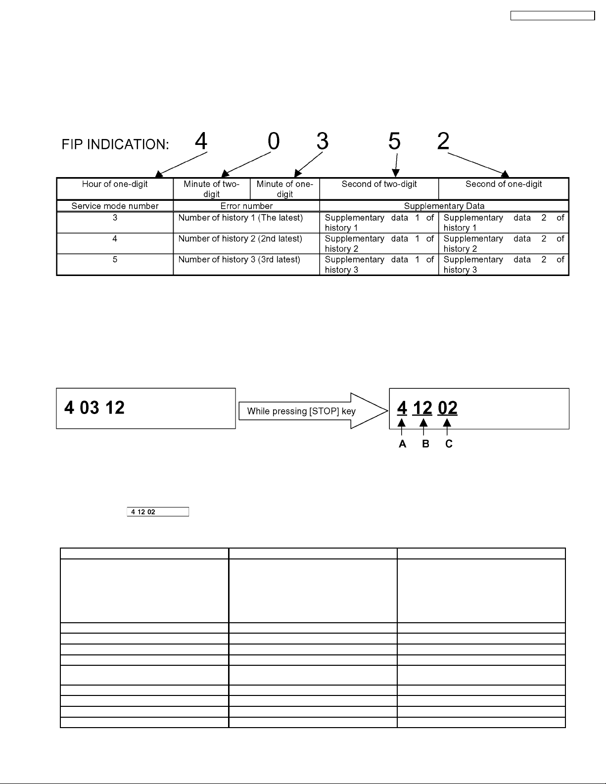
8.2.4.3. (VHS) Indication of the self-diagnosis history.
1. The self-diagnosis histories and its supplementary data could be indicated on the FIP with Service mode of number from 3 to
5.
2. The procedure of setting the service mode and the format if the indication are same as usual.
Both the Error numbers and its s upplementary data of history 1, 2and 3 are indicated by selecting the Service mode 3, 4 and 5 as
shown above.
In case of that any Error has not been memorized, the Error number and its supplementary data is indicated as " - ".
8.2.4.4. (VHS) Display of Supplementary Data 3 and 4
During displaying the Self-Diagnosis History, press [STOP] key on front panel to change the display.
*Example of Display
A: Service Mode Number.
B: Supplementary Data 3...Mechanism process shifting Number.
C: Supplementary Data 4...LM(Loading Motor information)
*Display of
occurred while mechanism was between REV position and LOAD position.
<Supplementary Data 3>
[EJECT] [FF] [REW]
10: PLAY ® passing REV
11: passing REV
12: passing REV ® LOAD
(Capstan STOP)
13: LOAD ® DOWN
14: DOWN ® EJECT
15: EJECT completion
[PLAY] [REC] [STILL]
20: Cylinder starting up, Phase drawing 30: Cylinder starting up, Phase drawing 40:Turning forward
21: Audio muting, VV selection 31: REC signal output 41:Speed is 0, Capstan is OFF
[P.ON] [STILL ® PLAY] [CUE]
-- Process of turning on power 48: Tape sending 49: x2 speed sending, Turning point of
[P.OFF] [CUE ® PLAY] [REV]
70: PLAY ® P.OFF 4A: Finishing edge Checking, Tape sending 80: PLAY ® P.OFF
means that " Loading Motor turns ON when [EJECT] button was pressed, but an error has
U0: PLAY ® STOP F
U1: STOP F ® FF
U2: FF starting up
4-: PLAY Checking, Tape sending 81: Rewinding
A0: PLAY ® STOP F
A1: STOP ® REW
A2: REW starting up
Calculating remains
P.OFF ® REV
29
DMR-ES45VP / DMR-ES46VP
<Supplementary Data 4> (LM Information)
Result of request of driving Loading Motor.
Display Description
1 There was no change of mechanism position. (Loading Motor was OFF)
2 There was some change of mechanism position. (Loading Motor was ON)
8.2.5. (VHS) Description of Self Diagnosis Memory
In this Self-Diagnosis Function, in case error has occurred continuously, maximum of the newest 3 error data are
memorized.
And in order to analyze cause of error, the error number and the supplementary data of mode, mechanism position and
so on are memorized.
8.2.5.1. (VHS) Error Number and Supplementary Data
The Supplementary Data as shown below are memorized to each error number.
Error No. Reason Supplementary Data
Data 1 Data 2 Data 3 Data 4
01 The cylinder could not be started.
(Error of the cylinder or the cylinder driver.)
02 The CAP FG could not be detected. VHS mode - Process No. Number of FG
03 Mechanism lock during without the unloading and the
cassette-up.
04 Mechanism lock during unloading VHS mode - Process No. LM information
05 S-reel pulse cannot be detected when a cassette
tape is inserted.
(Error of the S-reel system or the Capstan system.)
06 Mechanism lock during the Cassette-up. VHS mode Standby position Process No. LM information
07 The recording circuit can not be operated in REC
mode.
08 The recording circuit is operated in except for REC
mode.
09 Serial communication Error between VHS
Microprocessor (IC6001) and Timer Microprocessor
(IC7501).
11 Cylinder clogs during the PLAY mode. VHS mode - Process No. 15 S-reel pulse cannot be detected when a cassette
tape is inserted.
(Error of the S-reel system or the Capstan system.)
16 Detection of the Cylinder lock during the constant
rotation
17 Detection of S-reel lock during the constant tape
running
18 Detection of T-reel lock during the constant tape
running
20 NG1 in the PG Shifter Automatic Adjustment
(The cylinder rotation is unstable during the
automatic adjustment.)
21 NG2 in the PG Shifter Automatic Adjustment
(The vertical sync signal is lacked while over 5
seconds on the alignment tape.)
22 NG3 in the PG Shifter Automatic Adjustment
(The installing position of Heads to the cylinder is our
of specification.)
23 NG4 in the PG Shifter Automatic Adjustment
(The servo is not locked to the cylinder for more than
10 sec.)
80 An exceptional ejection depends on a Error VHS mode Refer to *Note 3 Process No. -
VHS mode - - -
VHS mode Standby position Process No. LM information
VHS mode Tape position Process No. LM information
VHS mode - Process No. -
VHS mode - Process No. -
- - - -
VHS mode Value of S-Reel Pulse
counted
VHS mode Tape position Process No. -
VHS mode Tape position Process No. Number of FG
VHS mode Tape position Process No. Number of FG
VHS mode - Process No. -
VHS mode - Process No. -
VHS mode - Process No. -
VHS mode - Process No. -
Process No. -
Note 1: Details of "VHS mode" of the Supplementary Data 1 (These values are hexadecimal indication)
0: STOP, 1: EJECT, 2: REW, 3: FF, 4:REV, 5: CUE, 6: SLOW, 7: POWEROFF, 8: PLAY, 9: STIL,
A: REC, B: REC PAUSE, C: ADUB, D: ADUB PAUSE, E: INSERT, F: INSERT PAUSE
Note 2: Explanation of "Tape position" of the Supplementary Data
The Tape position Data is the area data of S-reel that is used for judgment of reducing speed in the Main microprocessor
IC6001, and as the tape position is moved from the starting edge to the finishing edge, the value becomes smaller.
The Tape Data does not become "0" even if the tape reaches the finishing edge as the hub remains, and the tape position
values are different between the large hub and the small hub as the each diameters are different from each other.
30
 Loading...