

Panasonic DMRES-35-VEC, DMRES-35-VEG Service manual
ORDER NO.MAD0605013CE
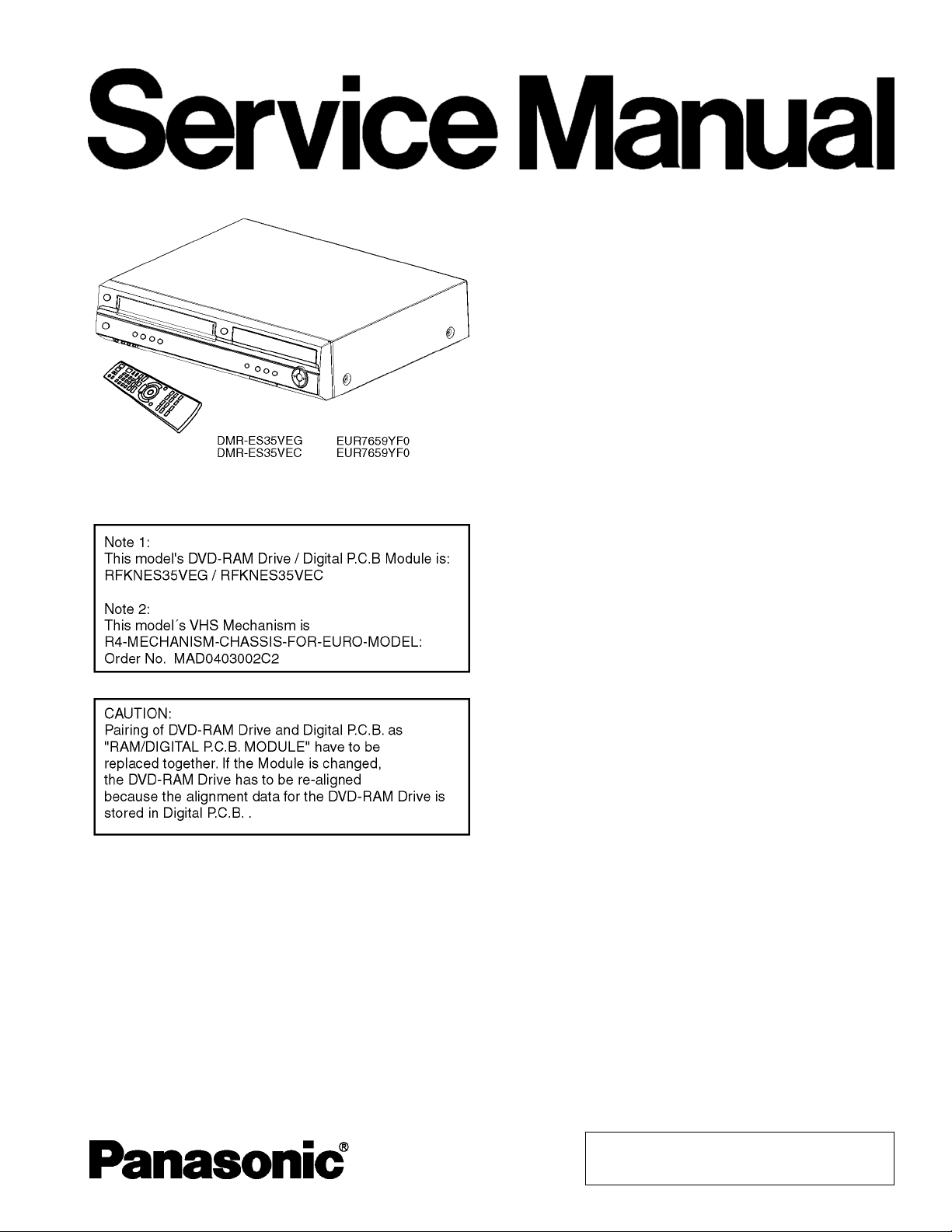
DVD Video Recorder
DMR-ES35VEG
DMR-ES35VEC
Vol. 1
Colour
(S).......................Silver Type
© 2006 Matsushita Electric Industrial CO., Ltd. All
rights reserved. Unauthorized copying and
distribution is a violation of law.
DMR-ES35VEG / DMR-ES35VEC
CONTENTS
Page Page
1 SAFETY PRECAUTIONS 3
1.1. GENERAL GUIDELINES
2 WARNING
2.1. PREVENTION OF ELECTROSTATIC DISCHARGE (ESD)
TO ELECTROSTATIC SENSITIVE (ES) DEVICES
2.2. PRECAUTION OF LASER DIODE
2.3. SERVICE CAUTION BASED ON LEGAL RESTRICTIONS
3 SERVICE NAVIGATION
3.1. SERVICE INFORMATION
3.2. CAUTION FOR DivX
4 SPECIFICATION
5 NEW FEATURE
5.1. ABOUT DivX
6 LOCATION OF CONTROLS AND COMPONENTS
7 OPERATING INTRUCTIONS
7.1. (DVD) TAKING OUT THE DISC FROM RAM-DRIVE UNIT
WHEN THE DISC CANNOT BE EJECTED BY
OPEN/CLOSE BUTTON
7.2. (VHS) REMOVING OF CASSETTE TAPE
8 SERVICE MODE
8.1. (DVD) SELF-DIAGNOSIS AND SPECIAL MODE
SETTING
8.2. (VHS) SELF-DIAGNOSIS AND SPECIAL MODE
SETTING
9 SERVICE FIXTURE AND TOOLS
10 ASSEMBLIN G AND DISASSEMB LING
10.1. DISASSEMBLY FLOW CHART
10.2. P.C.B. POSITIONS
10.3. CAUTION WHILE INSERTING CASSETTE TAPE WHEN
DISASSEMBLING THE UNIT
10.4. TOP CASE
10.5. FRONT PANEL
10.6. FRONT JACK P.C.B. & FL DRIVE P.C.B.
10.7. REAR PANEL & FAN MOTOR
10.8. VCR MECHANISM UNIT
10.9. MAIN P.C.B.
10.10. TUNER
10.11. DVD-RAM DRIVE / DIGITAL P.C.B. MODULE
10.12. DV IN P.C.B.
10.13. POWER & DIGITAL I/F P.C.B.
11 MEASUREM ENTS AND ADJUSTMENTS
11.1. SERVICE POSITIONS
11.2. CAUTION FOR REPLACING PARTS
15
16
16
17
19
19
28
30
31
31
31
31
32
32
33
33
34
35
35
36
37
38
39
39
42
3
4
4
5
6
7
7
7
8
9
9
11.3. (DVD) STANDARD INSPECTION SPECIFICATION
AFTER MAKING REPAIRS
12 MISCE LLANEOUS
12.1. ABBREVIATIONS
13 BLOCK DIAGRAM
13.1. POWER SUPPLY BLOCK DIAGRAM
13.2. SYSTEM CONTROL, SERVO & TIMER BLOCK
DIAGRAM
13.3. AUDIO BLOCK DIAGRAM
13.4. VIDEO BLOCK DIAGRAM
13.5. DIGITAL I/F P.C.B. BLOCK DIAGRAM
14 SCHE MATIC DIAGRAM
14.1. INTERCONNECTION DIAGRAM
14.2. POWER SUPPLY
14.3. DIGITAL I/F
14.4. IO / TUNER
14.5. SYSCON / SERVO / TIMER MAIN
14.6. VIDEO
14.7. AUDIO NICAM
14.8. FRONT JACK
14.9. FL DRIVE
14.10. DV IN
15 PRINT ED CIRCUIT BOARD
15.1. POWER & DIGITAL I/F P.C.B. (COMPONENT SIDE)
15.2. POWER & DIGITAL I/F P.C.B. (SOLDER SIDE)
15.3. MAIN P.C.B. (COMPONENT SIDE)
15.4. MAIN P.C.B. (SOLDER SIDE)
15.5. FRONT JACK P.C.B.
15.6. FL DRIVE P.C.B.
15.7. DV IN P.C.B.
16 APPENDIX FOR SCHEMATIC DIAGRAM
16.1. VOLTAGE AND WAVEFORM CHART
17 EXPLO DED VIEWS
17.1. MECHANISM & CASING PARTS
17.2. FRONT PANEL PARTS
17.3. VHS MECHANISM PARTS
17.4. PACKING & ACCESSORIES
18 REPL ACEMENT PARTS LIST
18.1. MECHANISM & CASING PARTS
18.2. VHS MECHANISM PARTS
18.3. PACKING & ACCESSORIES PARTS
18.4. ELECTRICAL PARTS
18.5. SERVICE FIXTURE AND TOOLS
47
48
48
55
55
56
57
58
60
61
61
62
63
64
65
66
67
68
69
70
71
71
72
73
74
75
76
77
79
79
91
91
92
93
94
95
95
95
96
96
105
2
1 SAFETY PRECAUTIONS
1.1. GENERAL GUIDELINES
1. Be careful during removing metal parts, sharp edges.
2. When servicing, observe the original lead dress. If a short
circuit is found, replace all parts which have been
overheated or damaged by the short circuit.
3. After servicing, see to it that all the protective devices such
as insulation barriers, insulation papers shields are properly
installed.
4. After servicing, make the following leakage current checks
to prevent the customer from being exposed to shock
hazards.
DMR-ES35VEG / DMR-ES35VEC
1.1.1. LEAKAGE CURRENT COLD
CHECK
1. Unplug the AC cord and connect a jumper between the two
prongs on the plug.
2. Measure the resistance value, with an ohmmeter, between
the jumpered AC plug and each exposed metallic cabinet
part on the equipment such as screw heads, connectors,
control shafts, etc. When the exposed metallic part has a
return path to the chassis, the reading should be between
1MΩ and 5.2MΩ.
When the exposed metal does not have a return path to
the chassis, the reading must be infinity.
Figure 1
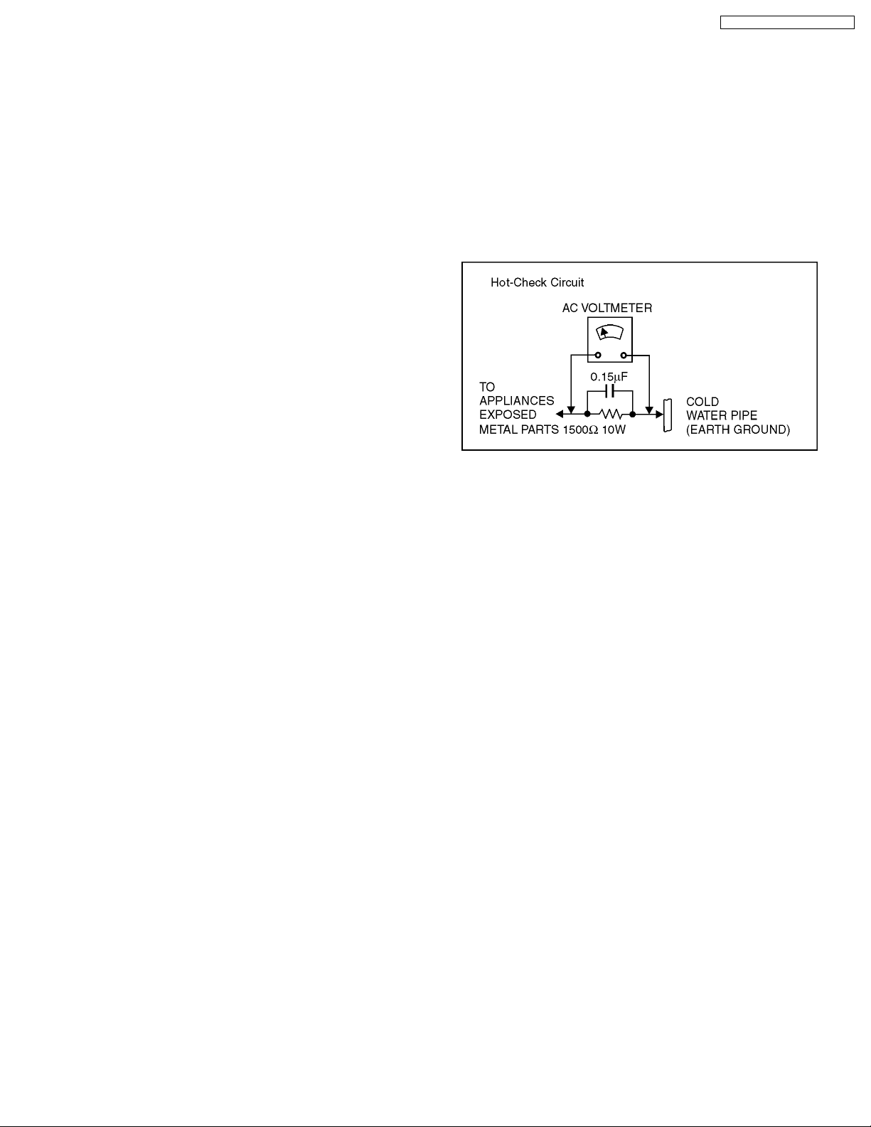
1.1.2. LEAKAGE CURRENT HOT CHECK
1. Plug the AC cord directly into the AC outlet. Do not use an
isolation transformer for this check.
2. Connect a 1.5kΩ, 10 watts resistor, in parallel with a 0.15µF
capacitors, between each exposed metallic part on the set
and a good earth ground such as a water pipe, as shown in
Figure 1.
3. Use an AC voltmeter, with 1000 ohms/volt or more
sensitivity, to measure the potential across the resistor.
4. Check each exposed metallic part, and measure the
voltage at each point.
5. Reverse the ACplugintheACoutlet and repeateach of the
above measurements.
6. The potential at any point should not exceed 0.75 volts
RMS. A leakage current tester (Simpson Model 229 or
equivalent) may be used to make the hot checks, leakage
current must not exceed 1/2 milliampere. In case a
measurement is outside of the limits specified, there is a
possibility of a shock hazard, and the equipment should be
repaired and rechecked before it is returned to the
customer.
3
DMR-ES35VEG / DMR-ES35VEC
2 WARNING
2.1. PREVENTION OF ELECTROSTATIC DISCHARGE (ESD) TO
ELECTROSTATIC SENSITIVE (ES) DEVICES
Some semiconductor (solid state) devices can be damaged
easily by static electricity. Such components commonly are
called Electrostatic Sensitive (ES) Devices. Examples of typical
ES devices are integrated circuits and some field-effect
transistor-sand semiconductor "chip" components. The
following techniques should be used to help reduce the
incidence of component damage caused by electrostatic
discharge (ESD).
1. Immediately before handling any semiconductor
component or semiconductor-equipped assembly, drain off
any ESD on your body by touching a known earth ground.
Alternatively, obtain and wear a commercially available
discharging ESD wrist strap, which should be removed for
potential shock reasons prior to applying power to the unit
under test.
2. After removing an electrical assembly equipped with ES
devices, place the assembly on a conductive surface such
as aluminum foil, to prevent electrostatic charge buildup or
exposure of the assembly.
3. Use only a grounded-tip soldering iron to solder
or unsolder ES devices.
4. Use only an anti-static solder removal device.
Some solder removal devices not classified
as "anti-static (ESD protected)" can generate electrical
charge sufficient to damage ES devices.
5. Do not use freon-propelled chemicals. These can generate
electrical charges sufficient to damage ES devices.
6. Do not remove a replacement ES device from its protective
package until immediately before you are ready to install it.
(Most replacement ES devices are packaged with leads
electrically shorted together by conductive foam, aluminum
foil or comparable conductive material).
7. Immediately before removing the protective material from
the leads of a replacement ES device, touch the protective
material to the chassis or circuit assembly into which the
device will be installed.
Caution
Be sure no power is applied to the chassis or circuit, and
observe all other safety precautions.
8. Minimize bodily motions when handling unpacked
replacement ES devices. (Otherwise harmless motion such
as the brushing together of your clothes fabric or the lifting
of your foot from a carpeted floor can generate static
electricity sufficient to damage an ES device).
4
DMR-ES35VEG / DMR-ES35VEC
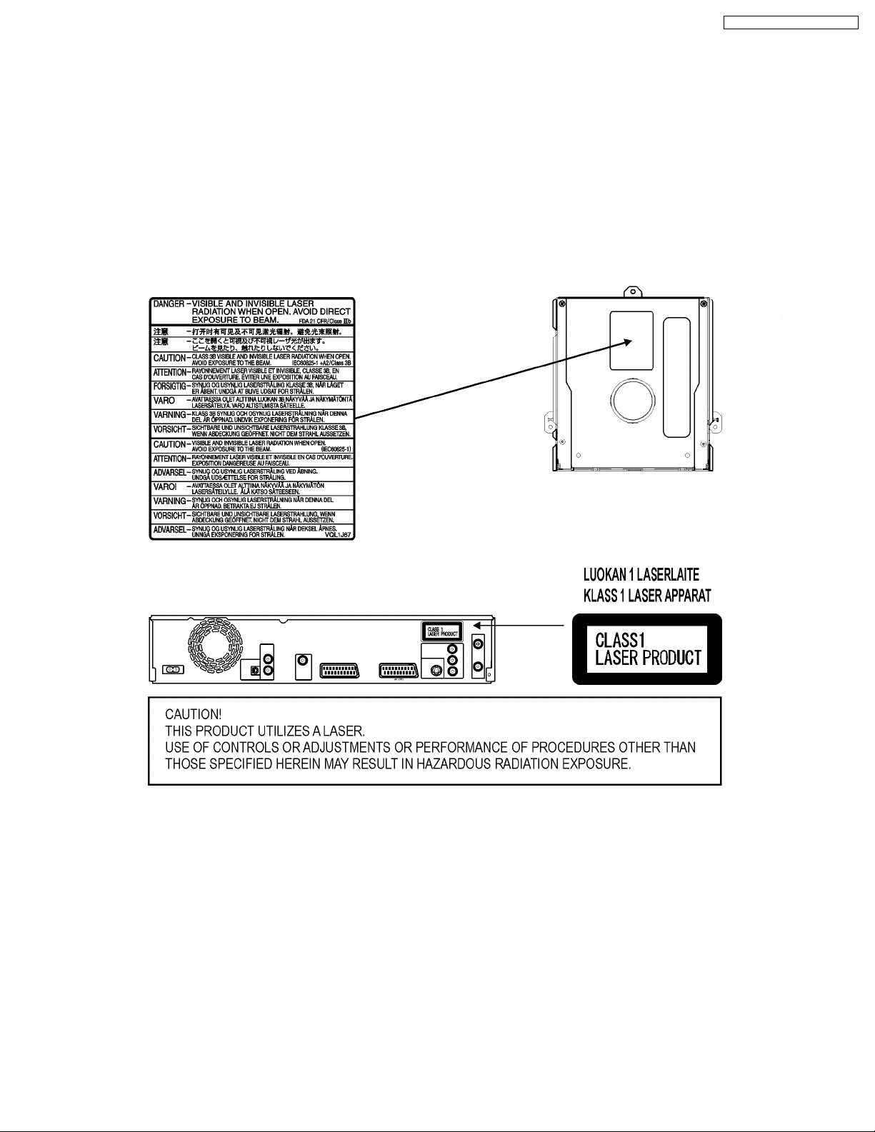
2.2. PRECAUTION OF LASER DIODE
CAUTION: ACHTUNG:
This product utilizes a laser diode with the unit turned “on”,
invisible laser radiation is emitted from the pickup lens.
Wave length: 662 nm/795 nm
Maximum output radiation power from pickup: 100µ W/VDE.
Laser radiation from the pickup lens is safety level, but be sure
the followings:
1. Do not disassemble the optical pickup unit, since radiation
from exposed laser diode is dangerous.
2. Do not adjust the variable resistor on the pickup unit.
It was already adjusted.
3. Do not look at the focus lens using optical instruments. 3. Nicht in die Fokussierlinse blicken.
4. Recommend not to look at pickup lens for a long time. 4. Auch nicht mit optischen Instrumenten in die Fokussierlinse blicken.
Dieses Produkt enthält eine Laserdiode.
Im eingeschalteten Zustand wird unsichtbare Laserstrahlung von der
Lasereinheit ausgestrahlt.
Wellenlänge: 662 nm/795 nm
Maximale Strahlungsleistung der Lasereinheit: 100µ W/VDE.
Die Strahlung der eingeschalteten Lasereinheit ist ungefährlich, wenn
folgende Punkte beachtet werden:
1. Die Lasereinheit nicht zerlegen, da die Strahlung an der freigelegten
Laserdiode gefährlich ist.
2. Den werksseitig justierten Einstellregler der Lasereinheit nicht
verstellen.
5

DMR-ES35VEG / DMR-ES35VEC
2.3. SERVICE CAUTION BASED ON LEGAL RESTRICTIONS
General description about lead free Solder (PbF)
· The lead free solder has been used in the mounting process of all electrical components on the printed circuit boards used
for this equipment in considering the globally environmental conservation.
· The normal solder is the alloy of tin (Sn) and lead (Pb). On the other hand, the lead free solder is the alloy mainly consists
of tin (Sn), silver (Ag) and Copper (Cu), and the melting point of the lead free solder is higher approx. 30 degrees C (86°F)
more than that of the normal solder.
Service caution for repair work using Lead Free Solder (PbF)
· The lead free solder has to be used when repairing the equipment for which the lead free solder is used.
· To put lead free solder, it should be well molten and mixed with the original lead free solder.
· Remove the remaining lead free solder on the PCB cleanly for soldering of the new IC.
· Since the melting point of the lead free solder is higher than that of the normal lead solder, it takes the longer time to melt
the lead free solder.
· Use the soldering iron (more than 70W) equipped with the temperature control after setting the temperature
at 350±30 degrees C (662±86°F). When soldering or unsoldering, please completely remove all of the solder
on the pins or solder area and be sure to heat the soldering points with the Pb free solder until it melts enough.
Definition of PCB Lead Free Solder being used
· The letter of “Pbf is printed either foil side or component side using the lead free solder.
Recommended Lead Free Solder (Service Parts Route.)
· The following 3 types of lead free solder are available through the service parts route.
RFKZ03D01K-----------(0.3mm 100g Reel)
RFKZ06D01K-----------(0.6mm 100g Reel)
RFKZ10D01K-----------(1.0mm 100g Reel)
Note
· Ingredient: tin (Sn), 96.5%, silver (Ag) 3.0%, Copper (Cu) 0.5%, Cobalt (Co) / Germanium (Ge) 0.1 to 0.3%
6
DMR-ES35VEG / DMR-ES35VEC
3 SERVICE NAVIGATION
3.1. SERVICE INFORMATION
This service manual contains technical information which will allow service personnel to understand and service these models.
Please place orders using the parts list and not the drawing reference numbers.
1. This service manual does not contain the following information, because of the impossibility of servicing at component level.
· Schematic Diagram, Block Diagram,
Exploded View, Parts List and P.C.B. layout of
RAM / Digital P.C.B. Module
2. The following categories are recycling module part.
Please send them to Central Repair Center.
· RAM / Digital P.C.B. Module:
DMR-ES35VEG: RFKNES35VEG
DMR-ES35VEC: RFKNES35VEC
3. If the circuit is changed or modified, this information will be followed by supplement service manual to be filed with original
service manual.
4. Adjustment procedures, Disassembly Procedures and Assembly Procedures for VCR Mechanism Chassis are separate volume
from this service manual. Please refer to the service manual for R4 Mechanism Chassis for EURO model (MAD0403002C2).
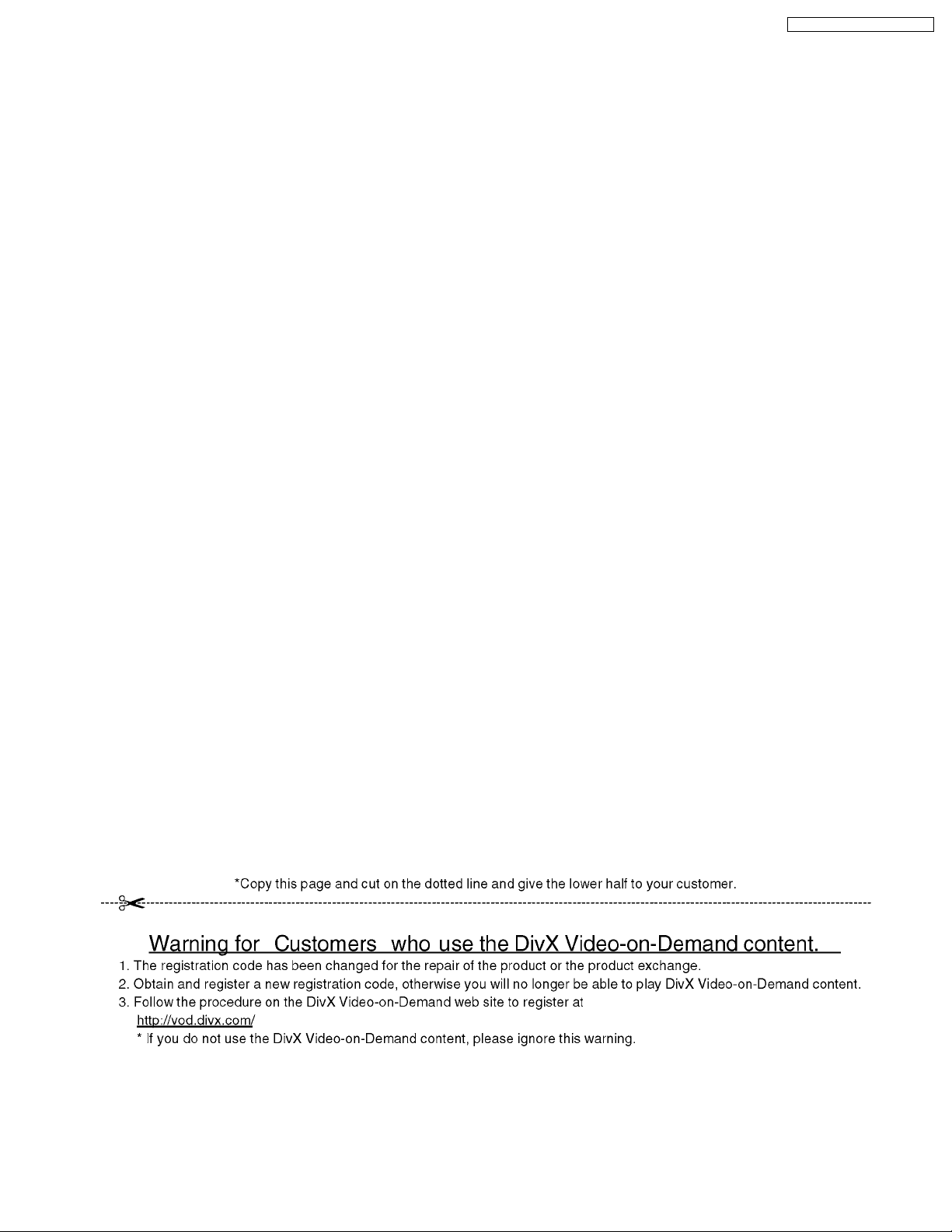
3.2. CAUTION FOR DivX
Please give the information “Warning for Customers who use the DivX Video-on-Demand content.” always to the customer
together with the product, if you have to exchange EEPROM, P.C.B. including EEPROM or the product itself.
Also attach these information to every service part (EEPROM or P.C.B. including EEPROM).
This complete Information is needed for every customer who is using the DivX Video-on-Demand Serivce.
Appendix:
* Parts that memorize userエs information are only on the EEPROM.
* The registration of Registration Code is possible for half a year up to 6 recorders up to 10 recorders a year.
Every replacement of EEPROM or P.C.B. including EEPROM spends one of this.
· Registration Code is memorized in the EEPROM (RFKFxxxxxxx)
· If the Power & Digital I/F P.C.B. or the EEPROM will be changed a new Registration Code
different from the previous one will be generated.
· In this case the customer, who is useing DivX Video-on-Demand sercive, can not longer play any content that
was or is purchased under that old registration code.
· Therefore the customer will need to register a new registration code.
7
DMR-ES35VEG / DMR-ES35VEC
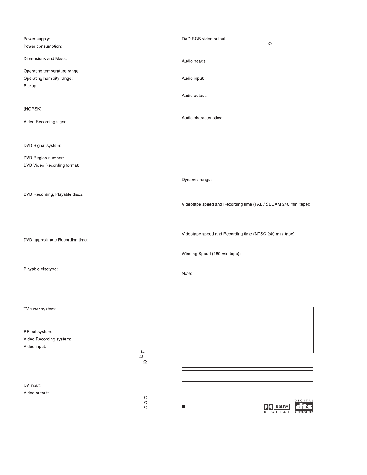
4 SPECIFICATION
AC 220-240 V, 50/60 Hz
26 W +/-1,3 W
Power Save mode: 2 W+/-0,4 W
430 (W) × 351 (D) × 84 (H) mm
(excluding protrusions) / 5.4 kg
+5 to +40°C
35 to 80 % RH (no condensation)
Laser power and Wave length: nm/780 nm
No hazardous radiation is emitted with the safety protection
Laser performance: Class 3 B / Class 3 A (optical scan unit)
Ølgelengde 662
B : nm / 780 nm
Laserstyrke Ingen farlig str
DVD-RAM: 12 cm 4.7 GB / 9.4 GB / 8 cm 2.8 GB
DVD-R: 12 cm 4.7 GB / 8 cm 1.4 GB
DVD-R Double Layer: 12 cm 8.5 GB
DVD-RW: 12 cm 4.7 GB
DVD+R: 12 cm 4.7 GB
DVD+R Double Layer: 12 cm 8.5 GB
DVD+RW: 12 cm 4.7 GB
XP: 10 MBps 60 min
SP: 5 MBps 120 min
LP: 3 MBps 240 min
EP: 1.7 / 1.2 MBps 360 - 480 min
CLASS 2/CLASS 1 / 662
åling sendes ut
PAL-BGH (EG / EC) PAL-I (EG)
MESECAM (EG / EC)
NTSC (only from extern and DVD)
SECAM-BG (only input)
PAL 625/50, PAL 525/60
NTSC (playback on PAL TV)
Region No. 2
DVD-RAM /
DVD-R/ DVD-RW/ DVD-R Double Layer/
DVD+R/ DVD+RW/ DVD+R Double Layer/
Video MPEG2 (Hybrid VBR)
Audio: Dolby Digital 2 CH
RGB output level: 0.7 Vp-p (75 ) +/-10 %
Output terminal: AV 1 (21 pin)
Number of terminals: 1 system
1 stationary head Mono
2 channels Hi-Fi Sound-Stereo
EURO AV (AV 1 / AV 2) 21 pin connector: -6 dB (500 mV)
AUDIO IN (AV 3 front input) cinch connector: -6 dB V (500 mV)
VHS / DVD cinch connector: -6 dB V (500 mV)
EURO AV (AV1 / AV2) 21 pin connector: -6 dB V (500 mV)
DVD optical output digital audio output
S/N ratio Normal: more than 43 dB (SP)
Hi-Fi: 65 dB
DVD: 115 dB
Frequence responce Normal: 80 Hz - 8 kHz
Hi-Fi: 20 Hz - 20 kHz
DVD: 4 Hz - 22 kHz (linear audio)
48 kHz sampling
DVD: 4 Hz - 44 kHz (linear audio)
96 kHz sampling
CD Audio: 4 Hz - 20 kHz
Total harmonic distortion: CD Audio: 0.0025 %
VCR: more than 90 dB
DVD (linear audio): more than 98 dB
CD audio: more than 96 dB
SP: 23.39 mm/s, 240 min.
LP: 11.695 mm/s, 480 min.
EP: 7.796 mm/s, 720 min.
FF / REW time: 60 sec. (180 min. tape)
SP: 33.35 mm/s, 168 min.
EP: 11.12 mm/s, 505 min.
FF time approximate 60 sec.
REW time approximate 43 sec.
µV
µ
µ
µ
DVD-Video, DVD-Audio
CD-Audio (CD-DA), Video CD, SVCD, DivX
CD-R/CD-RW (CD-DA, Video CD formatted discs)
MP3 (audio), JPG (picture)
Maximum number of tracks and groups recognizable:
999 tracks and 99 groups
VHF: CH E2-CH E12 A-H2 (Italien)
UHF: CH21-CH69
CATV: S01-S05 (S1-S3),
S1-S20 (M1-U10), S21-S41
without RF converter
4 rotary heads (helical scanning system)
EURO AV (AV 1 / AV 2) 21 pin connect. (1.0 Vp-p, 75 terminated)
VIDEO IN (AV 3 front input) cinch connect. (1.0 Vp-p, 75 terminated)
S-Video (front input) SVideo connect. (1.0 Vp-p, 75 terminated)
Component Video 3 cinch connector
(Y: 1.0 Vp-p, PB: 0,7 Vp-p, PR: 0,7 Vp-p)
625 I / 625 p, 525 I / 525 p (Progress Interl.)
IEEE 1394 Standard (4 pin) (PAL / NTSC)
EURO AV (AV 1 / AV 2) 21 pin connector (1.0 Vp-p, 75 terminated)
VHS / DVD cinch 21 pin connector (1.0 Vp-p, 75 terminated)
DVD (only) cinch 21 pin connector (1.0 Vp-p, 75 terminated)
Specifications are subject to change without notice.
Mass and dimensions are approximate.
MPEG Layer-3 audio decoding technology licensed from Fraunhofer
IIS and Thomson multimedia.
This product incorporates copyright protection technology that is
protected by method claims of certain U.S. patents and other
intellectual property rights owned by Macrovision Corporation and
other rights owners. Use of this copyright protection technology must
be authorized by Macrovision Corporation, and is intended for home
and other limited viewing uses only unless otherwise autherwise
authorized by Macrovision Corporation. Reverse engineering or
disassembly is prohibited.
Apparatus Claims of U.S. Patent Nos. 4,631,603, 4,577,216,
and 4,819,098, licensed for limited viewing uses only.
Manufactured under license from Dolby Laboratories. "Dolby" and
double-D symbol are trademarks of Dolby Laboratories.
"DTS" and "DTS 2.0 + Digital Out" are trademarks of Digital Theater
Systems, Inc.
Built-in decoders
You can play discs with these symbols
.
8
5 NEW FEATURE
5.1. ABOUT DivX
DMR-ES35VEG / DMR-ES35VEC
5.1.1. GENERAL
DivX is a new video compressing format that is applied
MPEG-4 technology to improve quality and the compressibility
and it is developed by the DivXNetworks, Inc., Video file of high
resolution and the high picture quality can be made thought it
is a high compressibility.
DivX codec is necessary for converting video to DivX file and
playback files made.
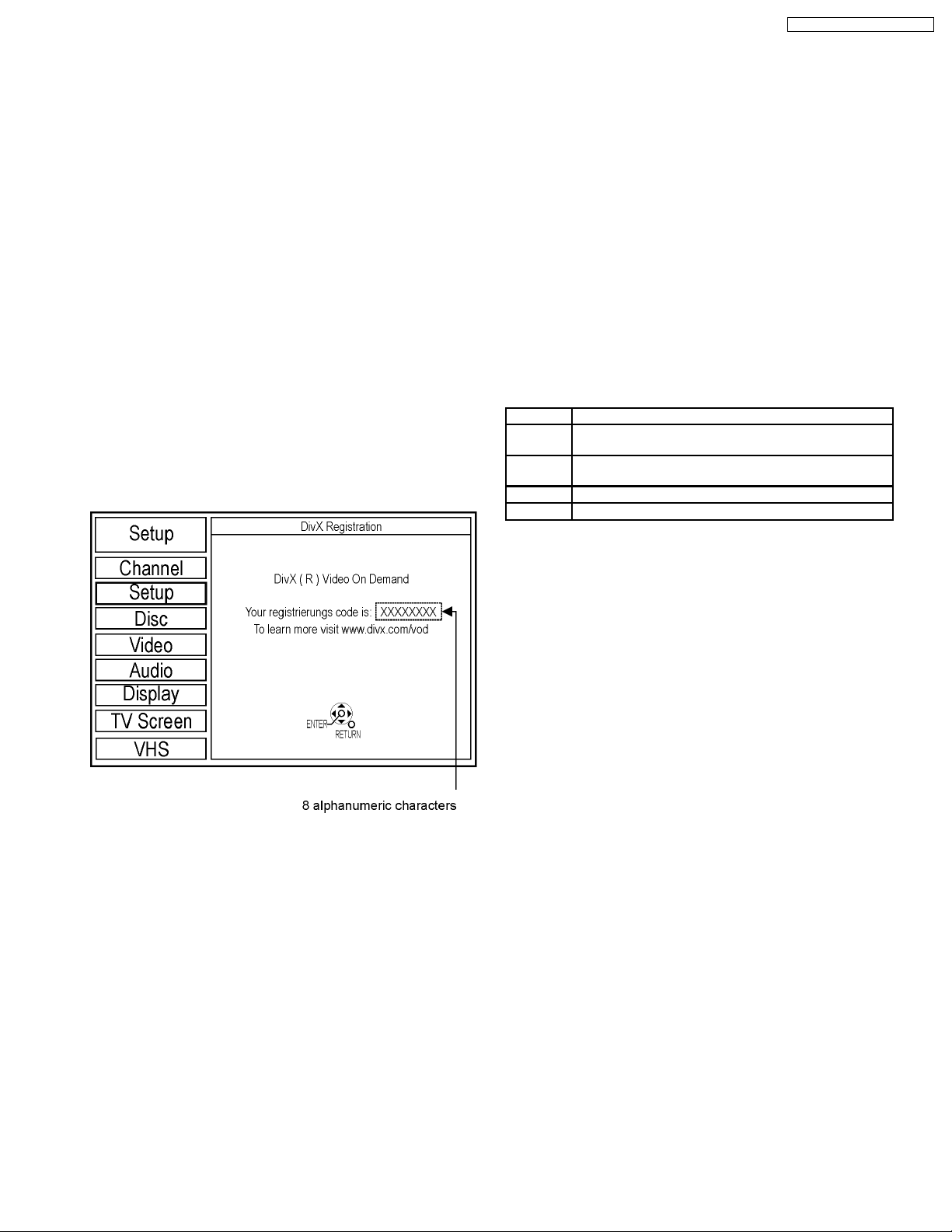
5.1.2. OPERATING INSTRUCTIONS
ABOUT DivX VIDEO-ON-DEMAND
CONTENT
DivX Video-on-Demand (VOD) content is encrypted for
copyright protection. In order to play DivX VOD content on this
unit, you first need to register the unit.
Follow the online instructions for purchasing DivX VOD content
to enter unit エ s registration code and register unit. Visit
www.divx.com/vod for mor information.
Display unitエs registration code:
When playing this content
· Number of remaining plays is reduced by one if
− you press [POWER]
− you press [STOP]
− you press [backwards SKIP],
[backwards SLOW / SEARCH] or
[forwards SLOW / SEARCH]
etc. and arrive at another content or start of content
being played.
− scheduled [DRIVE SELECT] to change drive
* Resume functions do not work.
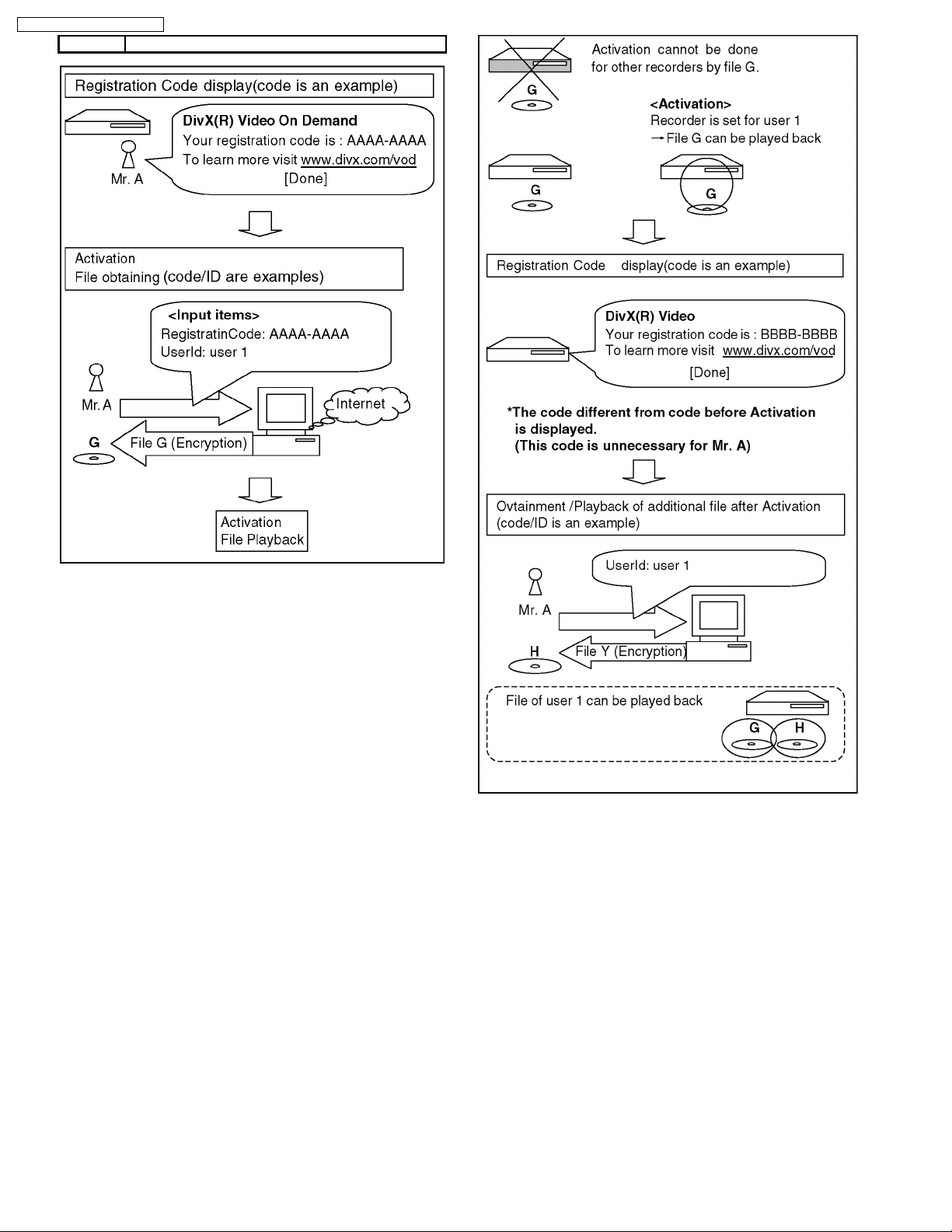
Typical Playback procedure of DivX VOD
(Video On Demand):
Case 1
Case 2
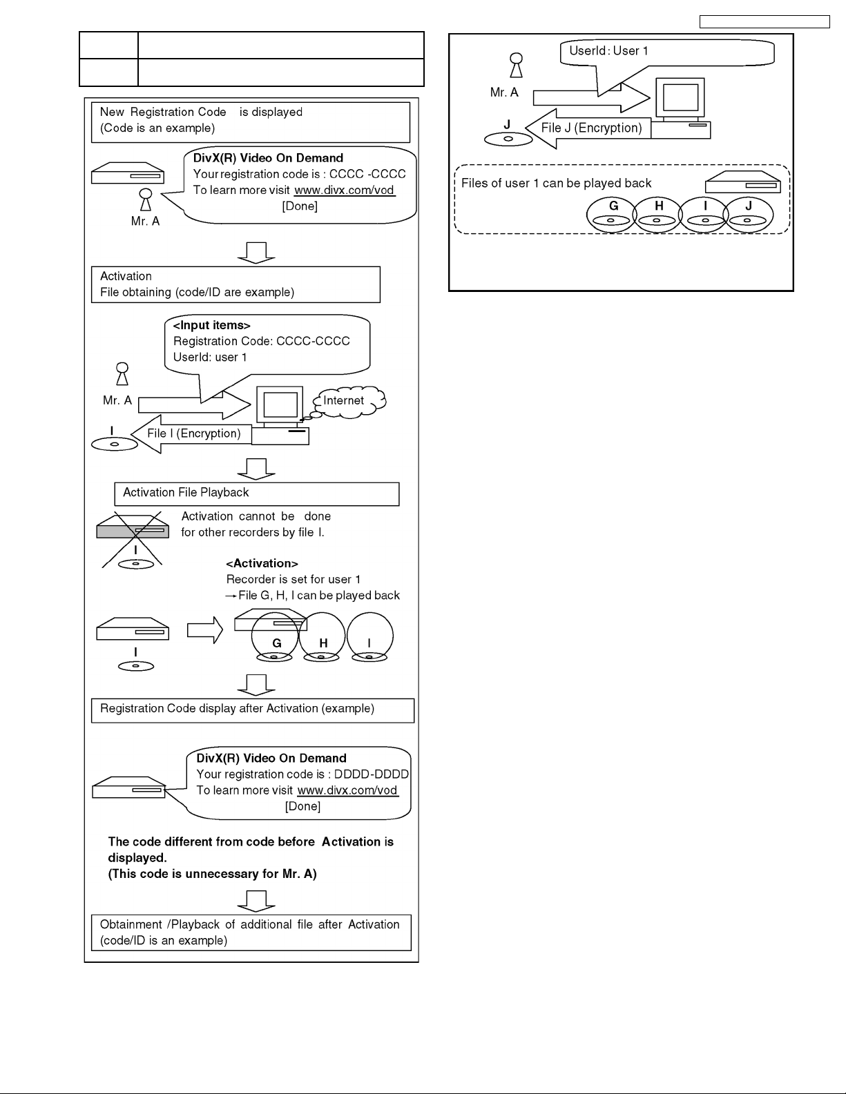
Case 3
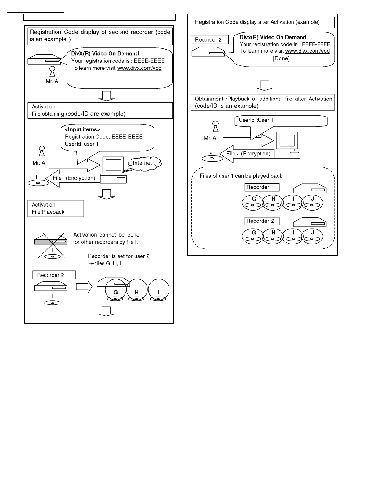
Case 4
Case 5
When DivX VOD is used newly.
When EEPROM or P.C.B. includin EEPROM was
replaced for repairing.
When recorder was exchanged to another recorder for
repairing.
When customer own second recorder.
When owner of recorder was changed to another.
· We recommend that you make a note of this code for future
reference.
· After playing DivX VOD content for first time, another
registration code is then displayed in “DivX Registration”. do
not use this registration code to purchase DivX VOD
content. If you use this code to purchase DivX VOD content
and the play content on this unit, you will no longer be able
to play any content that you purchased using previous
code.
· If you purchase DivX VOD content using a registration code
different from this unitエs code, you will not be able to play
this content. (“Authorization Error” is displayed.)
Some DivX VOD content can only be played a set number of
times.
When you play this content, remaining number of plays is
displayed. You cannot play this content when number of
remaining plays is zero. (“Rental Expired” is displayed.)
9
DMR-ES35VEG / DMR-ES35VEC
CASE 1 WHEN DivX IS USED NEWLY
Case 1
10
CASE 2 WHEN EEPROM OR P.C.B. INCLUDING EEPROM
WAS REPLACED FOR REPAIRING
CASE 3 WHEN RECORDER WAS EXCHANGED TO ANOTHER
RECORDER FOR REPAIRING
DMR-ES35VEG / DMR-ES35VEC
Case 3
Case 2
11
DMR-ES35VEG / DMR-ES35VEC
CASE 4 WHEN CUSTOMER OWN SECOND RECORDER
Case 4
12
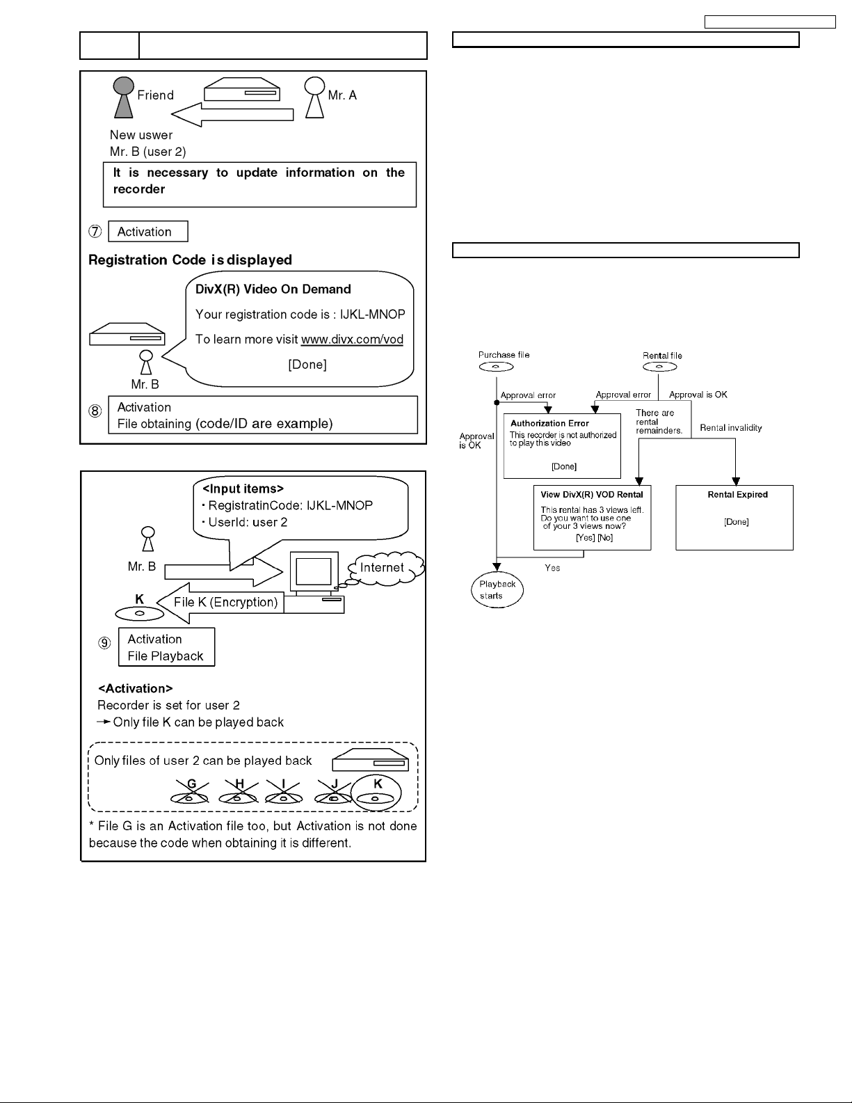
CASE 5 WHEN OWNER OF RECORDER WAS CHANGED TO
ANOTHER
DMR-ES35VEG / DMR-ES35VEC
FILE KIND
(There are two kinf of Activation files as follows too.)
· Rental: There is a playback limitation
· Purchase: Unrestricted
Also there is next file as DRM files besides the abovementioned.
· Base:
It is not necessary to approve though the contents is being
endode.
If it is recorder/player for DRM, any can play back. (It is the
same as usual DivX file when seeing from user.)
SCREEN SHIFT (Error display)
Wheter approval is OK or not.
Wheter the recorder is corresponding to User information on
the file or not.
Case 5
13

DMR-ES35VEG / DMR-ES35VEC
5.1.3. ABOUT DivX DRM
Divx file includes file to which DRM(Digital Right Management)
is applied and file not applied.
This item is a content that relates only in treating file
to which DRM is applied.
1. Registration Code display function
2. Userエs registration and approval function
3. Rental management function
1) Registration Code display function
Registration Code is alphanumeric character sequence
8 bytes inputted as recorder information, in case a use
purchases or renta DivX DRM file in a network.Registration
code is a character sequence generated
at random, and differs in each recorder.Moreover, Registration
code is updated by new user
authentication ever if same recorder.
2) Userエs registration and approval function
· Only one user can register for one recorder. If userエs
registration is not done with the recorder, DivX file cannot
be played back.
· Userエs registration is performed only when a DivX DRM
file is first chosen by recorder
· DivX DRM file that can perform userエs registration is only a
file that is registered Registration Code and purchased or
rented.
· User authentication is performed whenever DivX DRM file is
played back. Error message is displayed when failing in
userエs registration and approval.
· Conditions on counting number of times of play.
1. When a file was opened successfully. (At the time of
playback start)
2. When you have done review operation from the start.
(Skip to file head)
− At this time, remaining number of times that can be
played back and confirmation message
[Do you play really?] are displayed.
− When the playback point has been skipped to the
top of title, number of playback is not counted if the
top of title was not recognized.
− Even if the power failure occurs after start of
playback of rental file, number of times of playback
counted at start of the playback is held as it is.
(Though playback stops by power failure,
the number of times of playback is not counted.)
When it has reached head of title, the playback is ended,
and screen becomes DivX menu (There is no resume) and
then cursor is located on title that has been played
back.Then if the same file was continuously played back, it
begins to playback from the file head.
Note:
Above mentioned stored user information and number
of times of playback are not erased by update of
firmware or by initialization by test mode.
3) Rental management function
There are purchase file without registration of number of
playback and rental files with registration of number of playback
as Divx file. Number of playback of rental file is counted by the
recorder. When rental file is played, remaining number of times
that can be played back will be shown to users, recorder
requests users to input yes or no. Following specifications have
been installed for the rental files in the purpose to clarify the
count condition of number of times of playback.
14
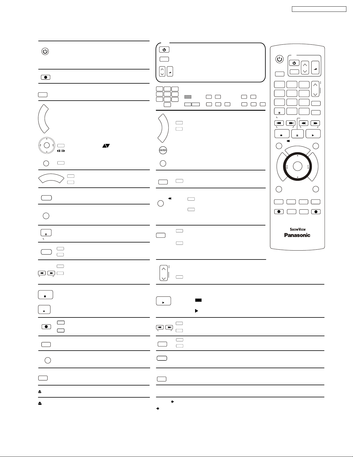
6 LOCATION OF CONTROLS AND COMPONENTS
Remote Control
DVD /VHS
Stand-by/on switch
Press to switch the unit from on to stand-by mode
or vice versa. In stand-by mode, the unit is still consuming
a small amount of power.
DIRECTT VREC
Direct TV record to DVD
DRIVE
SELECT
Buttons to switch between DVD and VHS
R
O
T
A
G
I
DIRECT NAVIGATOR TITLE VIEW
V
A
N
T
Main menu of DVD video.
C
E
R
I
D
Direction buttons in the menu navigation.
ENTER
DVD
Selection of groups or titles.
Still picture or time loop playback.
SUB MENU
DVD
S
O
R
P
STATUS
G
Launch sub-menus.
DVD
H
C
E
/
C
K
TIMER RECORDING menu
VHS
Timer recording menu
Time and detail information appears
on the screen for 5 seconds.
INPUT SELECT
Switch button of the AV input between AV1, AV2
and AV3 (front) / TP (DVD) and DC (VHS).
TV
Turn the television set on and off.
Select the AV input on the television set.
AV
+
CH: Select the channel on the television set.
VOLUME
CH
_
VOLUME: Volume control of the television set.
1
2
3
5
4
6
7
8
9
0
F
U
DVD
N
C
T
I
O
VHS
N
S
Select or save a setting.
RETURN
Exit a menu.
DISPLAY
TIME SLIP/ JET REW
DVD
B
Number buttons - direct input
VCD
MP3
0
5 5
5: + 15: +
JPEG
0 0 0
5: + + 15: + +
FUNCTIONS selection menu.
VHS FUNCTIONS menu.
Launch the disc menu.
DVD
TIME SLIP: Select the timeframe
to be skipped.
VHS
JET REW: Fast rewind to the
beginning of the cassette.
DVD/VHS
DRIVE
SELECT
1
55
4
7
CANCEL
RESET
SKIP/INDEX
STOP
TIME SLIP/ JET REW
SUB MENU
S
AUDIO
A
REC
1
1
DMR-ES35VEG / DMR-ES35VEC
TV
+
VOLUME
CH
TRACKING/V-LOCK
3
6
9
INPUT
SELECT
SLOW/SEARCH
REW
MANUAL SKIP
H
C
E
C
K
CREATE
CHAPTER
C
EXT LINK
_
CH
ShowView
DELETE
FF
PLAY
F
U
N
C
T
I
O
N
S
RETURN
STATUS
DIRECTT VREC
R
O
T
A
G
I
V
A
N
T
C
E
R
I
2
5
8
0
P
D
DISPLAY
B
REC MODE
AV
PAUSE
O
R
/
G
ENTER
+
-
CANCEL
RESET
ShowView
SLOW/SEARCH
REW
FF
STOP
PAUSE
REC
EXT LINK
MANUAL SKIP
DELETE
EJECT
OPEN/CLOSE
Cancel button
DVD
ShowView menu
VHS
ShowView menu
DVD
SLOW/SEARCH:
VHS
REW/FF:
Search or slow motion playback
Fast forward or rewind from stop mode.
Forward or reverse scene search during playback mode.
Stops recording, replay or forward .
/reverse action
Press and hold more than 3 seconds
to remove cassette.
Pause a recording or playback.
DVD
Record
VHS
Record
Record with external recording control
Only DVD:
Skip 30 sec. forward.
Delete:
Delete Title.
Front Panel Button: Remove cassette
Front Panel Button: Open and close the disc tray
AUDIO
A
TRACKING/V-LOCK
+
CH
-
PLAY
SKIP/INDEX
REC MODE
DVD ERASE
C
CREATE
CHAPTER
C
VHS/DVD
EXT LINK
DUBBING
DUBBING
DVD
Depending on the disc, select the audio
channel and or the sound track.
VHS
Press several times to select
sound playback mode.
CH: Channel select button.
TRACKING/V.LOCK + / -
VHS
Optimisation of the playback picture
.
Starts playback.
PLAY/ x1.3
RAM
You can increase the playback speed.
Hold PLAY during playback.
DVD
SKIP: Skip chapters, titles, or pictures.
VHS
INDEX: Search for the beginning of a recording.
DVD
Record mode button (XP, SP, LP, EP)
VHS
Record mode button (SP, LP, EP)
Erase a title during playback.
Move the selected station.
Split the recording into chapters.
Front Panel Button: Recording with external recording control
Front Panel Button: Copy from VHS to DVD
Front Panel Button: Copy from DVD to VHS
DVD/TV
EUR7659YF0
15
DMR-ES35VEG / DMR-ES35VEC
7 OPERATING INTRUCTIONS
7.1. (DVD) TAKING OUT THE DISC FROM RAM-DRIVE UNIT WHEN THE
DISC CANNOT BE EJECTED BY OPEN/CLOSE BUTTON
7.1.1. (DVD) FORCIBLE DISC EJECT
7.1.1.1. (DVD) WHEN THE POWER CAN
BE TURNED OFF.
1. Turn off the power and press [STOP], [CH UP] keys on the
front panel simultaneously for 5 seconds.
7.1.1.2. (DVD) THE POWER CAN NOT BE
TURNED OFF.
1. Press [POWER] key on the front panel for over 10 seconds
to turn off the power forcibly and press [STOP] [CH UP]
keys on the front panel simultaneously for 5 seconds.
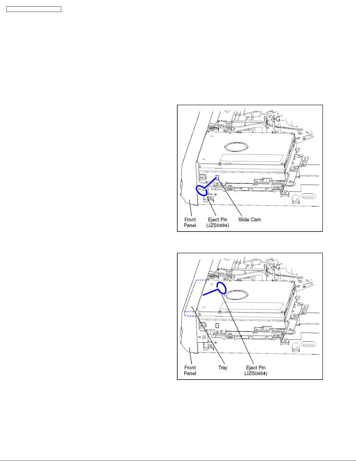
7.1.2. (DVD) WHEN THE FORCIBLE DISC
EJECT CAN NOT BE DONE.
1. Turn off the power and pull out AC cord.
2. Remove the Top Case.
3. Push in SLIDE CAM by Eject Pin(JZS0484) orminus screw
driver (small) to eject tray slightly.
4. Push out Tray by Eject Pin(JZS0484) or minus screw driver
(small).
16
7.2. (VHS) REMOVING OF
CASSETTE TAPE
When the cassette tape could not be removed after an
electrical malfunction, there are 2 ways to remove a cassette
tape.
7.2.1. (VHS) REMOVAL BY
COMPULSORY UNLOADING.
If Service Mode can be activated when the power can not be
turned on, this operation is able.
1. Press [STOP] and [EJECT] button simultaneously for more
than 3 seconds and set Drive to [VHS] and set the Service
Mode to 7.
2. Press [STOP] button in order to unload the mechanism.
(Pay attention to tape slack)
Service Mode Display:
7 ** ** (STOP) → 7 0L ** (EJECT)
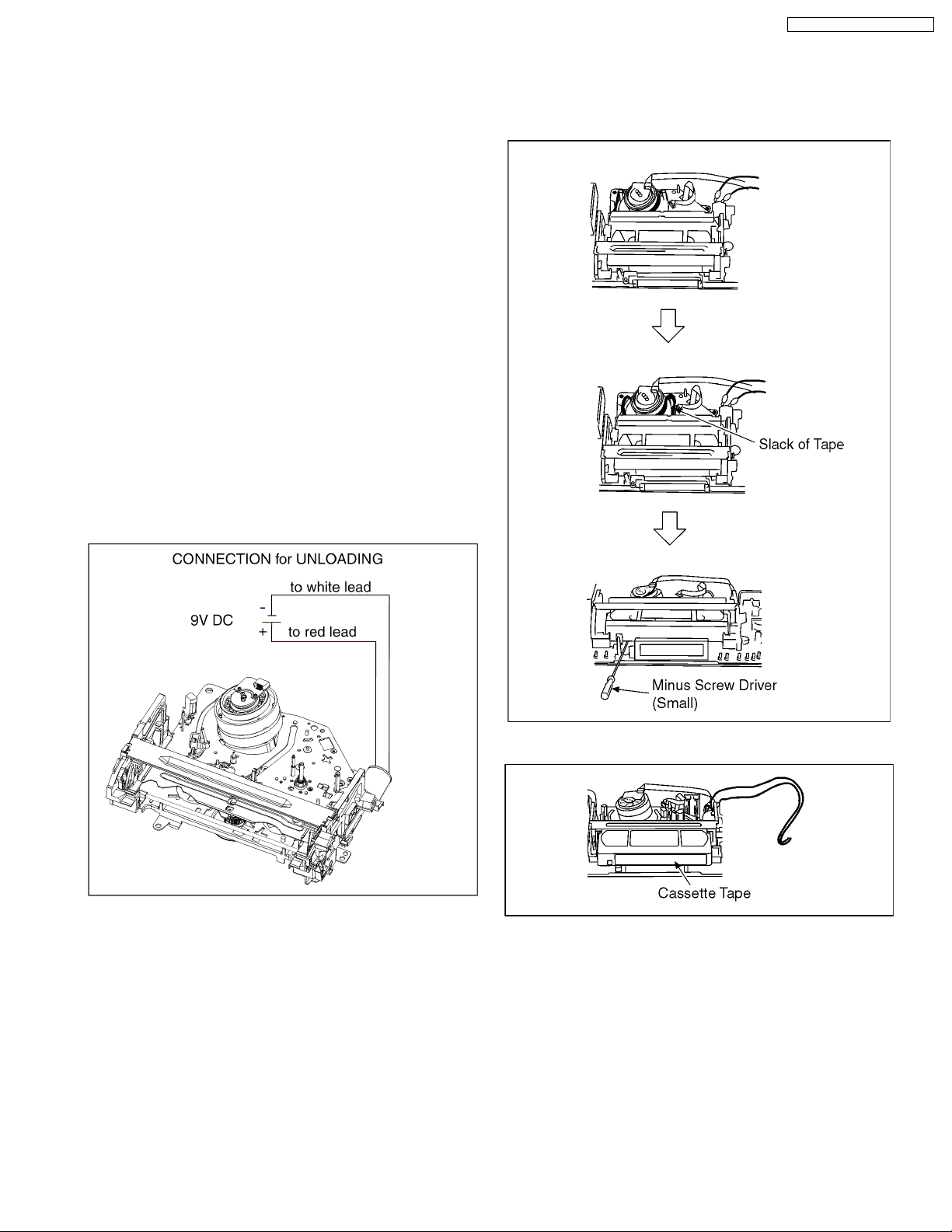
7.2.2. (VHS) REMOVAL BY MANUAL
OPERATION.
1. Disconnect the AC plug, and remove the Top Panel and the
Front Panel by referring to the Disassembly Procedures.
2. Connect a batterie (9V spec.) to the Loading Motor inseries
for supplying 9V to rotate the Loading Motor.
DMR-ES35VEG / DMR-ES35VEC
3. Stop unloading just before unloading willbe completed. The
tape becomes slack.
4. Rotate the S-Reel by a small minus screwdriver to remove
the slack tape.
5. Then unload again to remove the cassette tape.
17
DMR-ES35VEG / DMR-ES35VEC
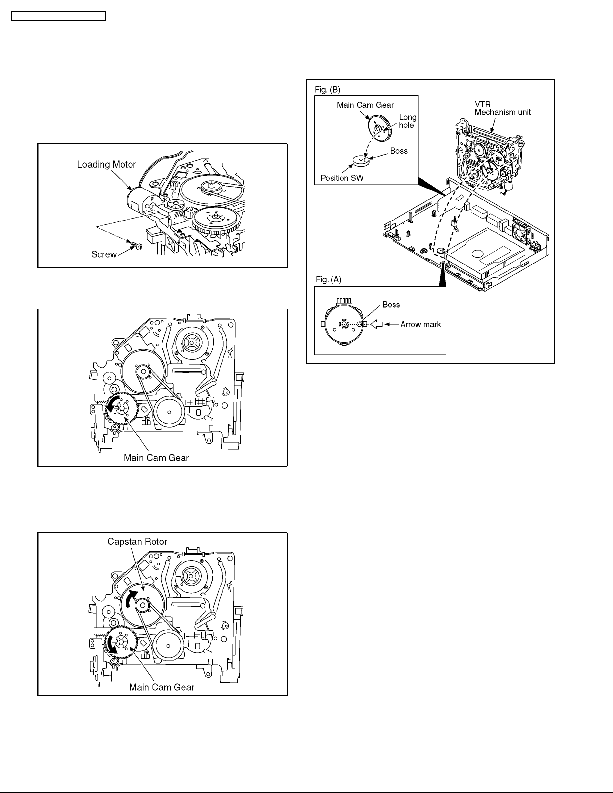
7.2.3. (VHS) TAKE OUT CASSETTE TAPE
MANUALLY AFTER REMOVING
THE MECHANNISM
1. Disconnect the AC plug, and remove the Top Panel, Front
Panel and the Mechanism by referring assembling and
disassembling description.
2. Remove the Screw and remove the Loading Motor.
3. Rotate the Main Cam Gear counter-clockwise until just
before the unloading will be completed.
6. Attach Loading Motor and tighten the screw.
7. Set the Position Switch to EJECT POSITION certainly and
attach the mechanism to chassis.
4. Rotate the Capstan Motor clockwise to remove the slack
tape.
5. Rotate the Main Cam Gear counter-clockwise again to
remove the cassette-tape.
18
DMR-ES35VEG / DMR-ES35VEC
8 SERVICE MODE
8.1. (DVD) SELF-DIAGNOSIS AND SPECIAL MODE SETTING
8.1.1. (DVD) SELF-DIAGNOSIS FUNCTIONS
Self-Diagnosis Function provides information for errors to service personnel by “Self-Diagnosis Display” when any error has
occurred.
U**, H** and F** are stored in memory and held.
You can check latest error code by transmitting [0] [1] of Remote Controller in Service Mode.
Automatic Display on FL will be cancelled when the power is turned off or AC input is turned off during self-diagnosis display is ON.
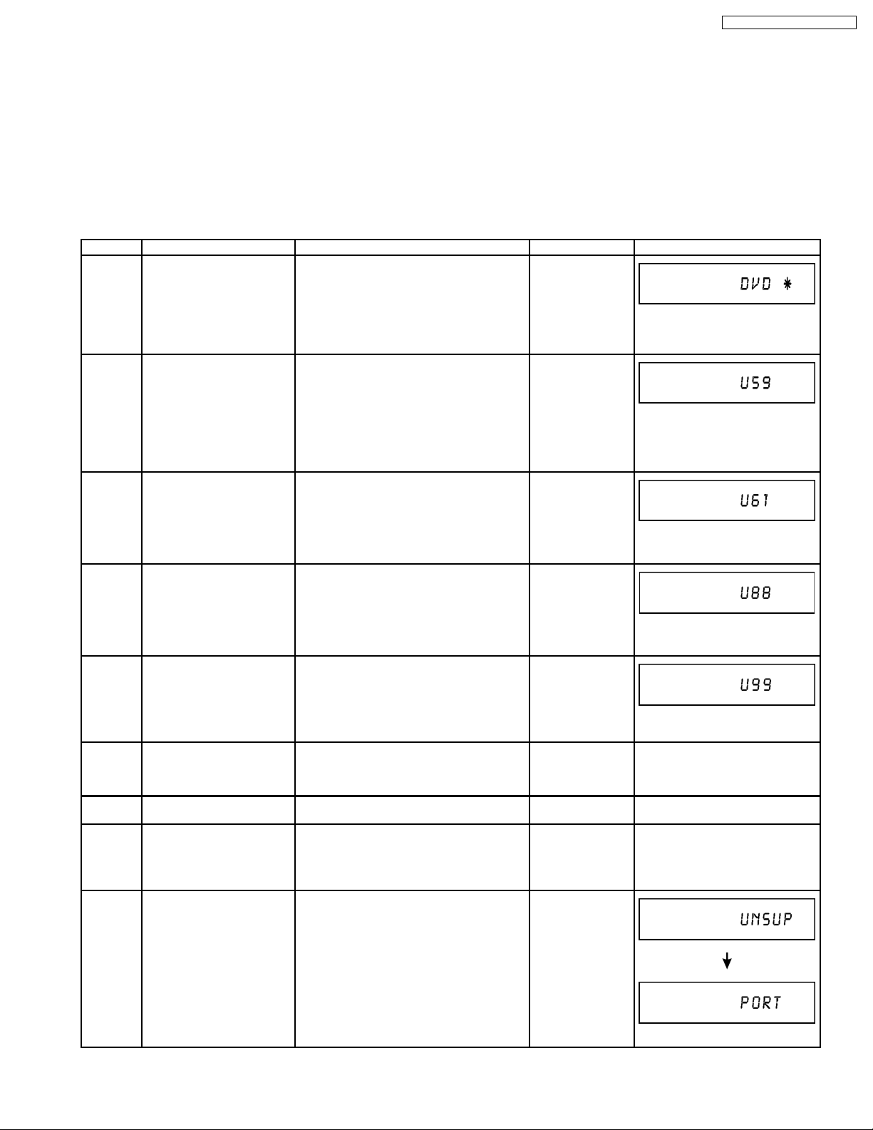
Error Code Diagnosis contents Description Monitor Display Automatic FL display
U30 Remote control code error Display appears when main unit and remote
U59 Abnormal inner temperature
detected
U61 The unit is carrying out its
recovery process (with no
disc in the disc tray).
U88 The unit is carrying out its
recovery process (with no
disc in the disc tray).
U99 Hang-up Displayed when communication error has
controller codes are not matched.
Display appears when the drive temperature
exceeds 70°C.
The power is turned off forcibly.
For 30 minutes after this, all key entries are
disabled. (Fan motor operates at the highest
speed for the first 5 minutes. For the
remaining 25 minutes, fan motor is also
stopped.) The event is saved in memory as
well.
* The unit detected an error while recording
or playing with with no disc in the disc
tray.
The unit is carrying out its recovery process.
This process restores the unit to normal
operation. The unit is not broken. Wait until
the message disappears.
* The unit detected an error while recording
or playing with with no disc in the disc
tray.
The unit is carrying out its recovery process.
This process restores the unit to normal
operation. The unit is not broken. Wait until
the message disappears.
occurred between Main microprocessor and
Timer microprocessor.
No display
“*” is remote controller code of the
main unit.
Display for 5 seconds.
No display
“U59 is displayed for 30 minutes.
No display
No display
No display
F00 No error information Initial setting for error code in memory
F58 Drive hardware error When drive unit error is detected, the event
F34 Initialization error when main
UNSUPPORT
microprocessor is started up
for program recording
Unsupported disc error *An unsupported format disc was played,
(Error code Initialization is possible with error
code initialization and main unit
initialization.)
is saved in memory.
When initialization error is detected after
starting up main microprocessor for program
recording, the power is turned off
automatically.
The event is saved in memory.
although the drive starts normally.
*The data format is not supported, although
the media type is supported.
*Exceptionally in case of the disc is dirty.
19
Displayed is left until the [POWER]
key is pressed.
No display No display
No display No display
No display No display
“This disc is
incompatible.”
Display for 5 seconds.
DMR-ES35VEG / DMR-ES35VEC
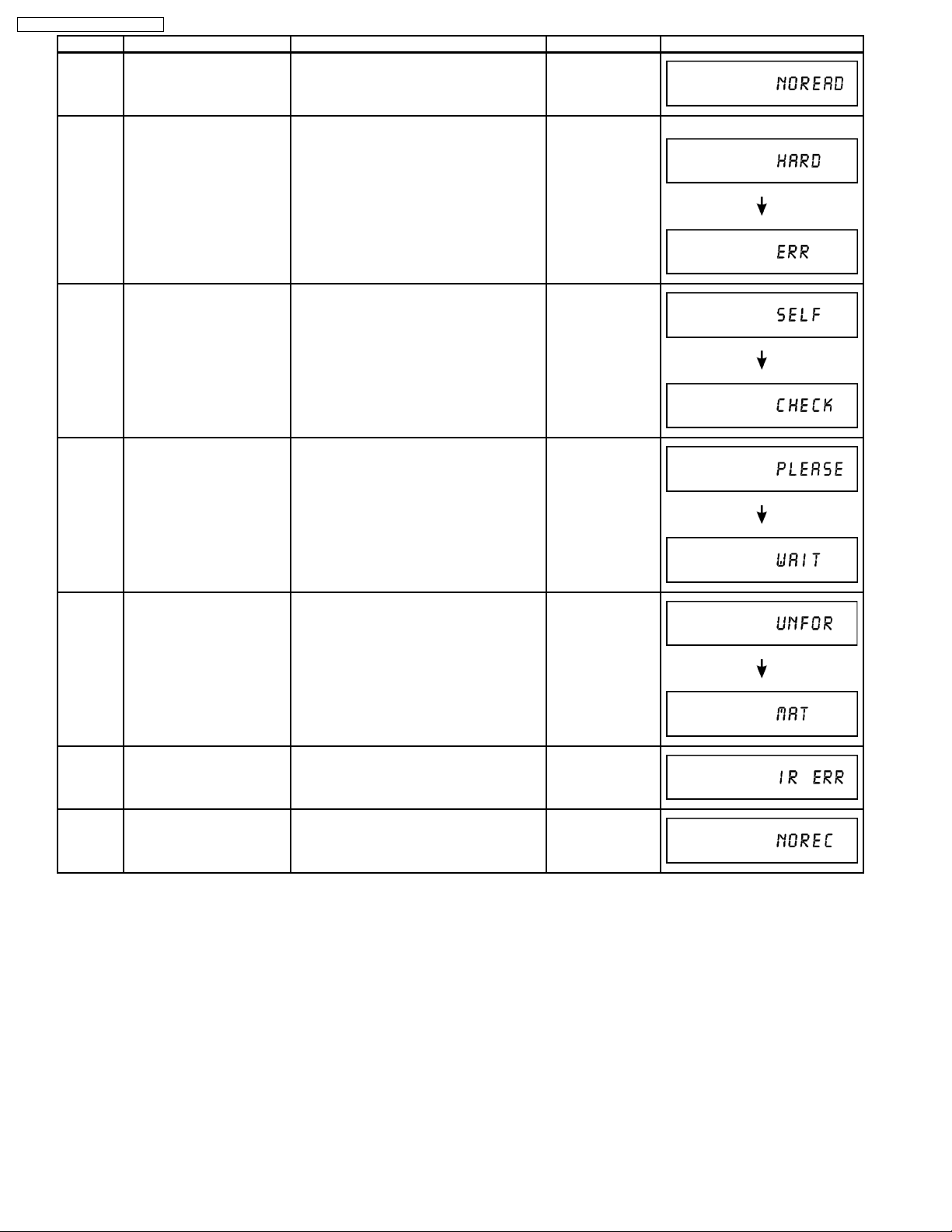
Error Code Diagnosis contents Description Monitor Display Automatic FL display
NO READ Disc read error *A disc is flawed or dirty.
*A poor quality failed to start.
*The track information could not be read.
“Cannot read.
Please check the
disc.”
HARD
ERR
SELF
CHECK
PLEASE
WAIT
Drive error The drive detected a hard error. “DVD drive error.” Display for 5 seconds.
Restoration operation Since the power cord fell out during a power
No display
failure or operation, it is under restoration
operation.
*It will OK, if a display disappears
automatically. If a display does not
disappear, there is the possibility that
defective Digital P.C.B. / RAM drive.
Unit is in termination process Unit is in termination process now.
No display
“BYE” is displayed and power will be turned
off.
In case “Quick Start” of setup menu is ON, it
is displayed in restoration operation for AC
off.
UNFORMAT
Unformatted disc error You have inserted an unformatted DVD-
RAM or DVD-RW that is unformatted or
recorded on other equipment.
IR ERR IR communication error [IR ERR] is display when communication
between Timer microprocessor and IR
microprocessor fails.
No REC Recording is impossible [No REC] is displayed when recording is
impossible due to the defect, dirt or wound
of media.
Format:
This disc is not
formatted properly.
Format the disc in
DISK
MANAGEMENT?
No display
No display
20
8.1.2. SPECIAL MODES SETTING
Item FL display Key operation
Mode name Description Front Key
TEST Mode *All the main unit´s parameters (include
tuner) are initialized.
Rating password The audiovisual level setting password is
initialized to “Level 8”.
Press [VHS to DVD COPYING],
[REC] and [OPEN/CLOSE] keys
simultaneously for five seconds
when power is off.
Open the tray, and press [REC]
and [PLAY] simultaneously for 5
seconds.
DMR-ES35VEG / DMR-ES35VEC
Service Mode Setting every kind of modes for servicing.
Forced disc eject Removing a disc that cannot be ejected.
Child lock/unlock Set or release “Child Lock”. Press [ENTER] and [RETURN] by
NTSC/PAL system select To switch PAL/NTSC altemately. The display before execution
Forced power-off When the power button is not effective while
Aging Perform sequence of modes as * Aging
*Details are described in “Service Mode”.
The tray will open and unit will shift to P-off
mode.
*When Timer REC is ON or EXT-LINK is
ON, execute " Forced disc eject " after
releasing Timer REC or EXT-LINK.
*This command is not effective during "Child
lock" is ON.
While Demonstration Lock is being set, this
Forced disc eject function is not accepted.
If this command was executed while
TIMER REC is being set, TIMER REC
setting will turn to OFF.
power is ON, turn off the power forcibly.
*When Timer REC is ON or EXT-LINK is
ON, execute “Forced Power-off” after
releasing Timer REC or EXT-LINK.
Description shown below continually.
Caution:
All programs in DVD-RAM disc will be
deleted because Formatting is done once
in Aging process.
The display before execution
leaves.
leaves.
Display in P-off mode. Press [Power] key over than 10
Display following the then mode. When the power is ON, press [CH
When the power is off, press
[STOP], [OPEN/CLOSE] and [VHS
to DVD COPYING] keys
simultaneously for 5 seconds.
When the power is off, press
[STOP] and [CH UP] keys
simultaneously for 5 seconds.
remote controller simultaneously
until [X-HOLD] is displayed.
While the power is on (E-E mode),
press [STOP] and [OPEN/CLOSE]
simultaneously for 5 seconds.
seconds.
DOWN], [VHS to DVD COPYING]
and [OPEN/CLOSE]
simultaneously for over 5 seconds
and less than 10 seconds.
NOTE1:
If Unit has not turned into Aging
mode by operations shown above,
execute TEST MODE once and reexecute operation shown above.
(*All the main unit’s parameters
include tuner are initialized by
TEST mode.)
21
NOTE2:
If the unit has hung-up because of
pressing keys for over 10 seconds,
once turn off the power, and reexecute this command.
*When releasing Aging mode,
press [POWER] key.
DMR-ES35VEG / DMR-ES35VEC
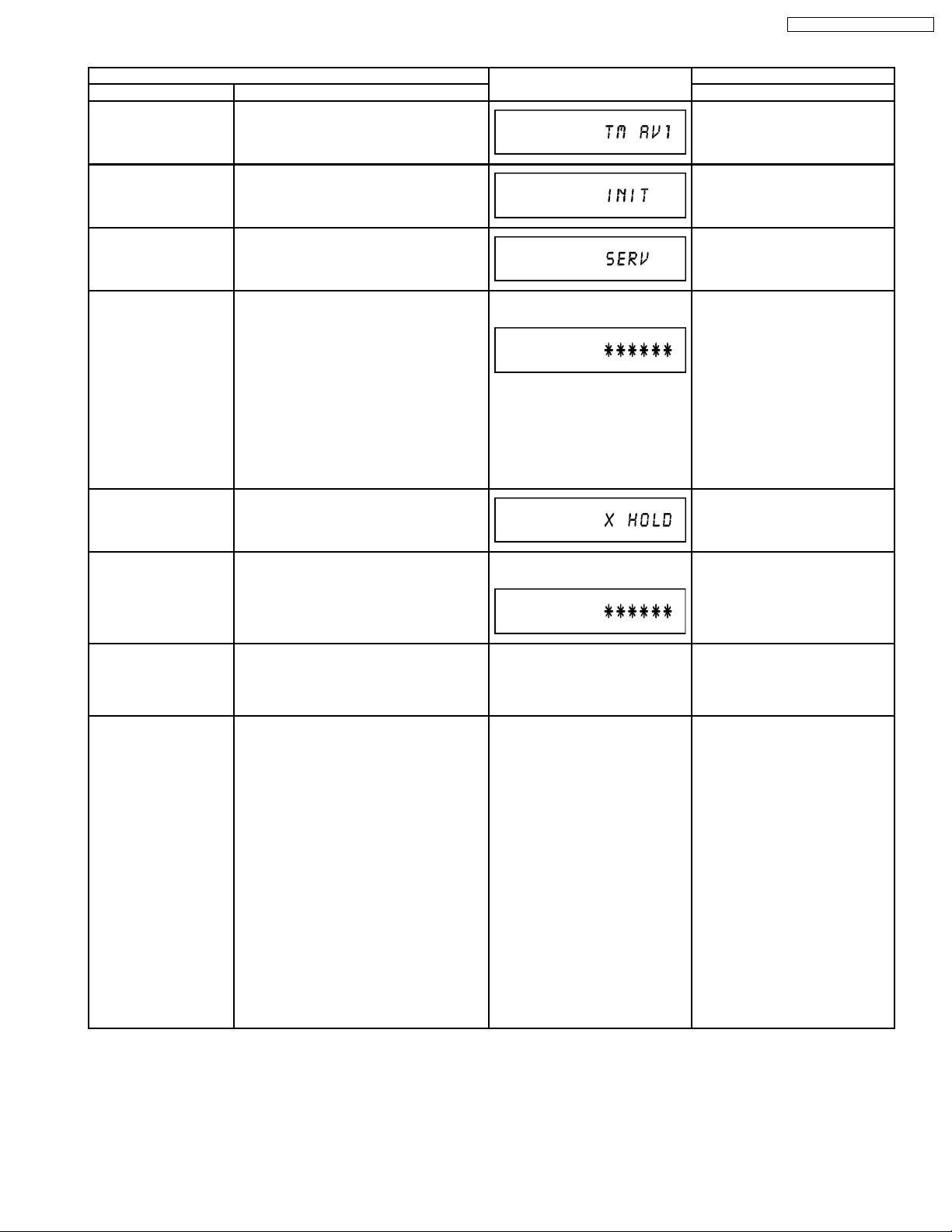
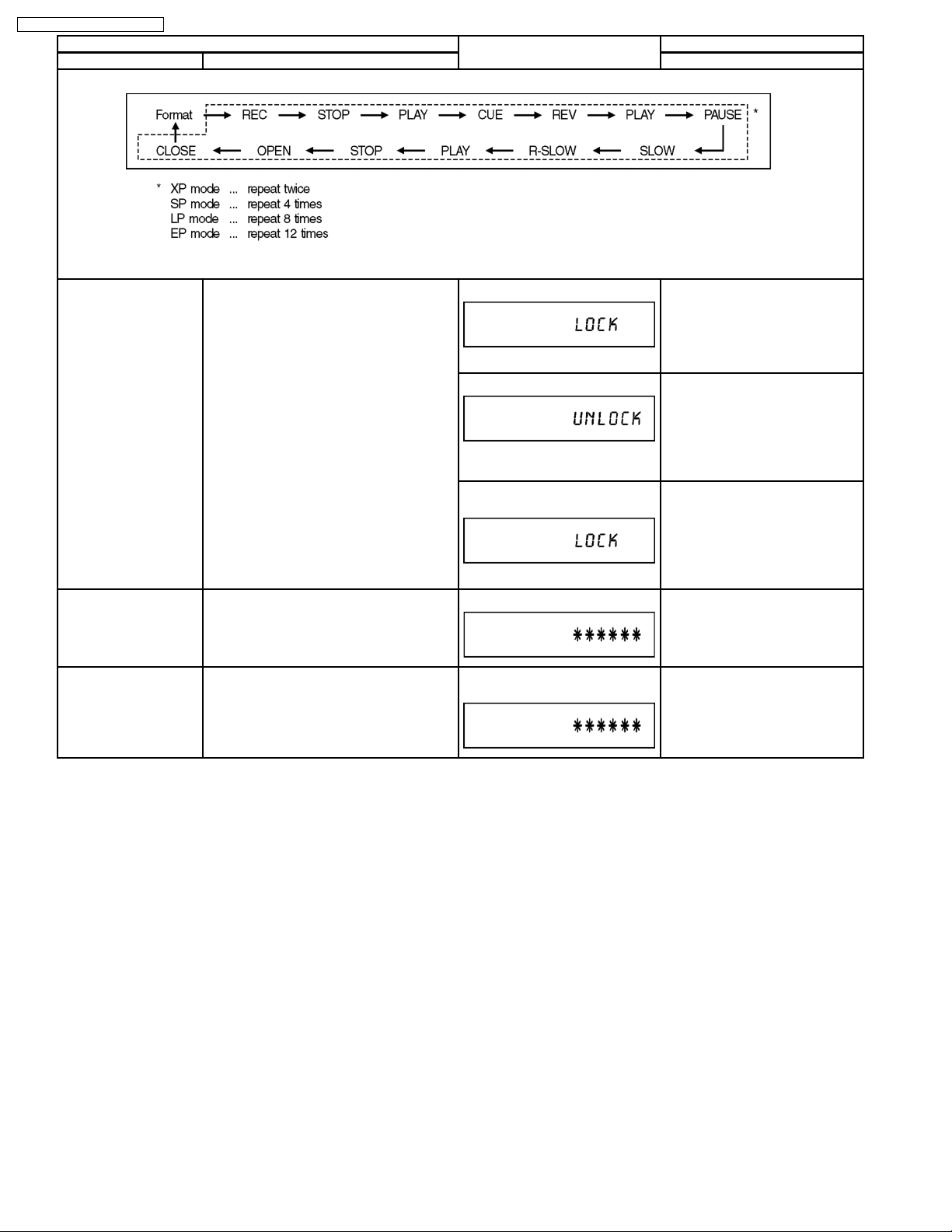
Mode name Description Front Key
Item FL display Key operation
Aging Contents (Example):
Demonstration
lock/unlock
ATP re-execution Re-execute ATP. Display at ATP executing. When the power is on (E-E mode),
Progressive initialization The progressive setting is initialized to
Ejection of the disc is prohibited.
The lock setting is effective until unlocking
the tray and not released by “Main unit
initialization” of service mode.
Interlace.
*When lock the tray.
“LOCK” is displayed for 3 seconds.
*When unlock the tray.
“UNLOCK” is displayed for 3
seconds.
*When press OPEN/CLOSE key
while the tray being locked.
Display “LOCK” for 3 seconds.
The display before execution
leaves.
When the power is on, press
[STOP] and [POWER] keys
simultaneously for 5 seconds.
When the power is on, press
[STOP] and [POWER] keys
simultaneously for 5 seconds.
Press [OPEN/CLOSE] key while
the tray being locked.
press [CH UP] and [CH DOWN]
simultaneously for 5 seconds.
When the power is on (E-E mode),
press [STOP] and [VHS to DVD
COPYING] simultaneously for 5
seconds.
22
DMR-ES35VEG / DMR-ES35VEC
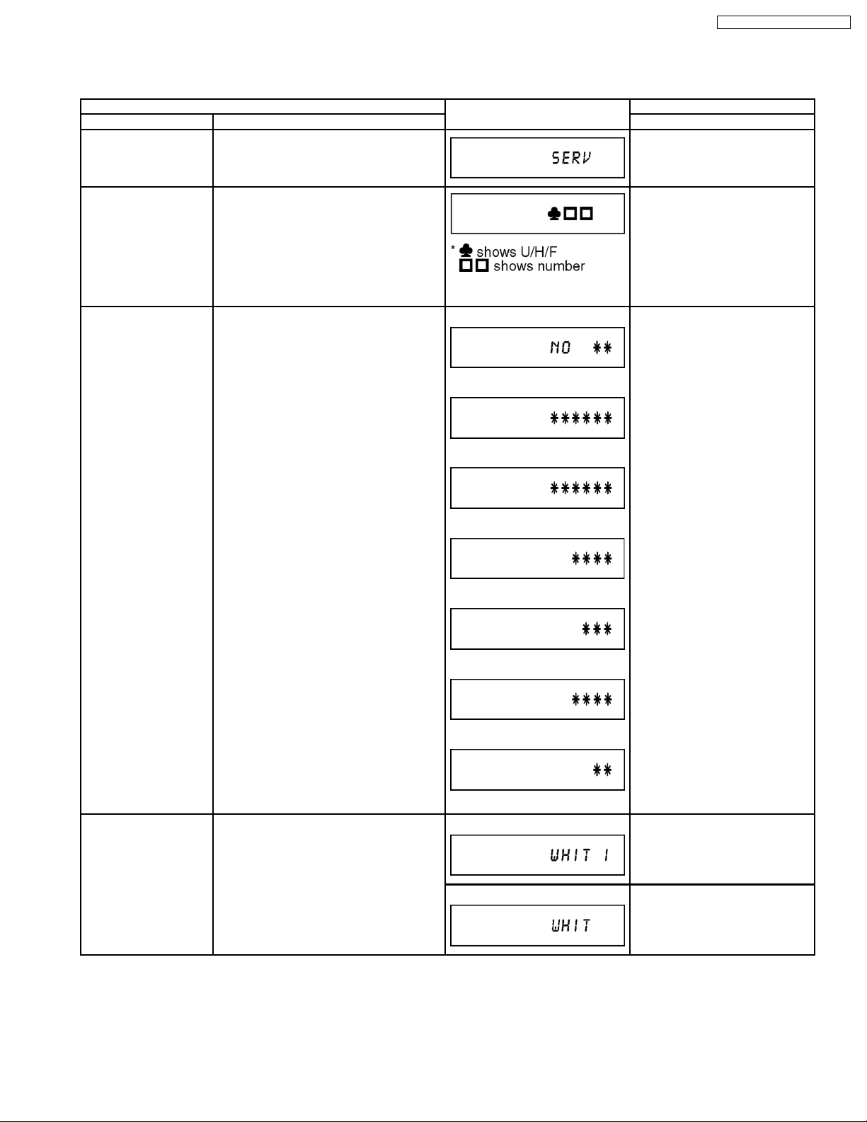
8.1.3. (DVD) SERVICE MODES
Service mode setting: While the power is off, press [STOP], [VHS to DVD COPYING] and [OPEN/CLOSE] simultaneously for five
seconds.
Item FL display Key operation
Mode name Description (Remote controller key)
Release Items Item of Service Mode executing is cancelled. Press [0] [0] or [Return] in service
mode.
Error Code Display Last Error Code of U/H/F held by Timer is
displayed on FL.
*Details are described in “Self-Diagnosis
Functions”.
ROM Version Display 1. Region code
(displayed for 5 sec.)
2. Main firm version
(displayed for 5 sec.)
3. Timer firm version
(displayed for 5 sec.)
4. Drive firm version
(displayed for 5 sec.)
5. ROM correction version
(displayed for 5 sec.)
6. VHS Microprocessor version
(displayed for 5 sec.)
7. VHS ROM Correction version
(left displayed)
If any error history dose not exist,
[F00] is displayed.
1.
2.
3.
4.
5.
Press [0] [1] in service mode
Press [0] [2] in service mode
White Picture Outpu t White picture is output as component Output
from AV Decoder.
*White picture
(Saturation rate : 100%)
*It is enable to switch Interlace/Progressive
by “I/P switch: [1] [4]”
6.
7.
‘’ ’’ are version displays.
*Initial mode is “Interlace”. Press [1] [1] in service mode.
Switch Interlace/Progressive Press [1] [4] in White Picture
Output mode.
*I/P are switched alternately.
23

DMR-ES35VEG / DMR-ES35VEC
Item FL display Key operation
Mode name Description (Remote controller key)
Magenta Picture Output Magenta picture is output with Component
Output from AV Decoder.
*Magenta picture
(Saturation rate: 100%)
*It is enable to switch Interlace/Progressive
by “I/P switch: [1] [4]”
*Initial mode is “Interlace”. Press [1] [2] in service mode.
Switch Interlace/Progressive Press [1] [4] in Magenta Picture
Output mode.
*I/P are switched alternately.
RTSC Return in XP
(A & V)
AV1 input signal is encoded (XP), decoded
(XP) and output decoded signal to external
without DISC recording and DISC playback.
I/P Switch Switch Interlace and Progressive in EE
mode.
*Initial setting is “Interlace”.
*This command is effective during executing
“White Picture Outpu t”, “Magenta Picture
Output” and “RTSC Return in XP (A & V)”
modes.
Audio Mute (XTMUTE) Check whether mute is applied normally by
the timer microprocessor.
Initial mode: EE2/ Interlace/ XP/
Press [1] [3] in service mode.
Audio 48kHz
Switch Interlace/Progressive Press [1] [4] in RTSC Return XP
mode.
*I/P are switched alternately.
Audio 44.1 kHz/ 48 kHz Switch Press [2] [4] in RTSC Return XP
mode.
*48 kHz / 44.1 kHz are switched
alternately.
Initial mode is Interlace
Press [1] [4] in I/P Switch mode.
*I/P are switched alternately.
Switch Interlace/Progressive
Press [2] [1] in service mode.
Audio Mute (XDMUTE) Check whether mute is applied normally by
the Digital P.C.B..
Audio Pattern Output The audio pattern stored in the internal
memory is output
(Lch: 1kHz/-18dB)
(Rch: 400Hz/-18dB)
*Audio sound clock switching operation of
DAC can be confirmed by sub command [2]
[4].
Laser Used Time
Check laser used time (hours) of drive.
Indiction
Delete the Laser Used
Time
Laser used time stored in the memory of the
unit is deleted.
Press [2] [2] in service mode.
Initial mode (Audio 48kHz) Press [2] [3] in service mode.
Audio 44.1kHz/48kHz switching Press [2] [4] in Audio Pattern
Output mode.
*48 kHz / 44.1 kHz are switched
alternately.
Press [4] [1] in service mode.
●(*****) is the used time display in
hour.
●Laser used time of DVD/ CD in
Playback/Recording mode is
counted.
Press [9] [5] in service mode.
24
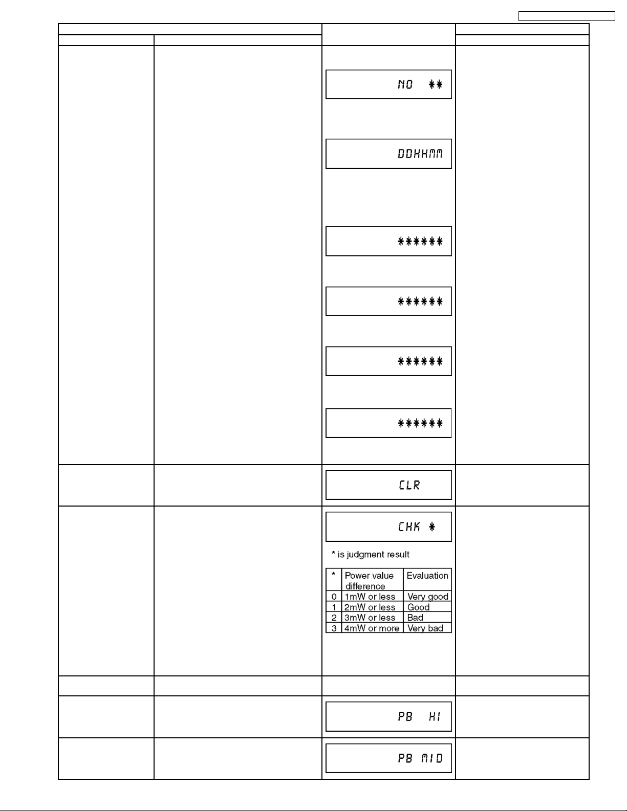
Item FL display Key operation
Mode name Description (Remote controller key)
RAM Drive Last Error RAM Drive error code display.
*For details about the drive error code, refer
to the Service Manual for the specific RAM
Drive.
1. Error Number is displayed for 5
seconds.
Press [4] [2] in service mode.
When “INFO******” is being
displayed, past 19 error histories
can be displayed by pressing [0]
[1] - [1] [9]
2. Time when the error has
occurred is displayed for 5
seconds.
DD: Day
hh: Hour
mm: Minute
3. Last Drive Error (1/2) is
displayed for 5 seconds.
4. Last Drive Error (2/2) is
displayed for 5 seconds.
DMR-ES35VEG / DMR-ES35VEC
Delete the Last Drive
Error
Delete the Last Drive Error information
stored on the DVD RAM-Drive.
Laser power confirmation Drive state is judged based on difference
between laser power value at shipping and
present laser power value.
5. Error occurring Disc type is
displayed for 5 seconds.
6. Disc Maker ID is displayed for 5
seconds.
In case that the maker cannot be
identified, display is black out.
7. Factor of Drive Error occurring is
left displayed
Press [9] [6] in service mode.
1. Insert DVD-RAM disc
into RAM Drive in service
mode. (Other media are
assumed to be noncorrespondence.)
2. Press [4] [4].
Turn on all FL/LEDs All segments of FL and all LEDs are turned
on.
PB HIGH Signal Output 8 pin of AV 1 Jack (PB HIGH terminal) is
High (approx. 11V DC).
PB MIDDLE Signal
Output
8 pin of AV 1 Jack (PB HIGH terminal) is
Middle (approx. 5.5V DC)
If DVD-RAM disc in not inserted,
[NO DISC] is displayed.
If power value study was filed,
[ERROR] is displayed.
All segments are turned on. Press [5] [1] in service mode.
Press [5] [2] in service mode.
Press [5] [3] in service mode.
25
DMR-ES35VEG / DMR-ES35VEC
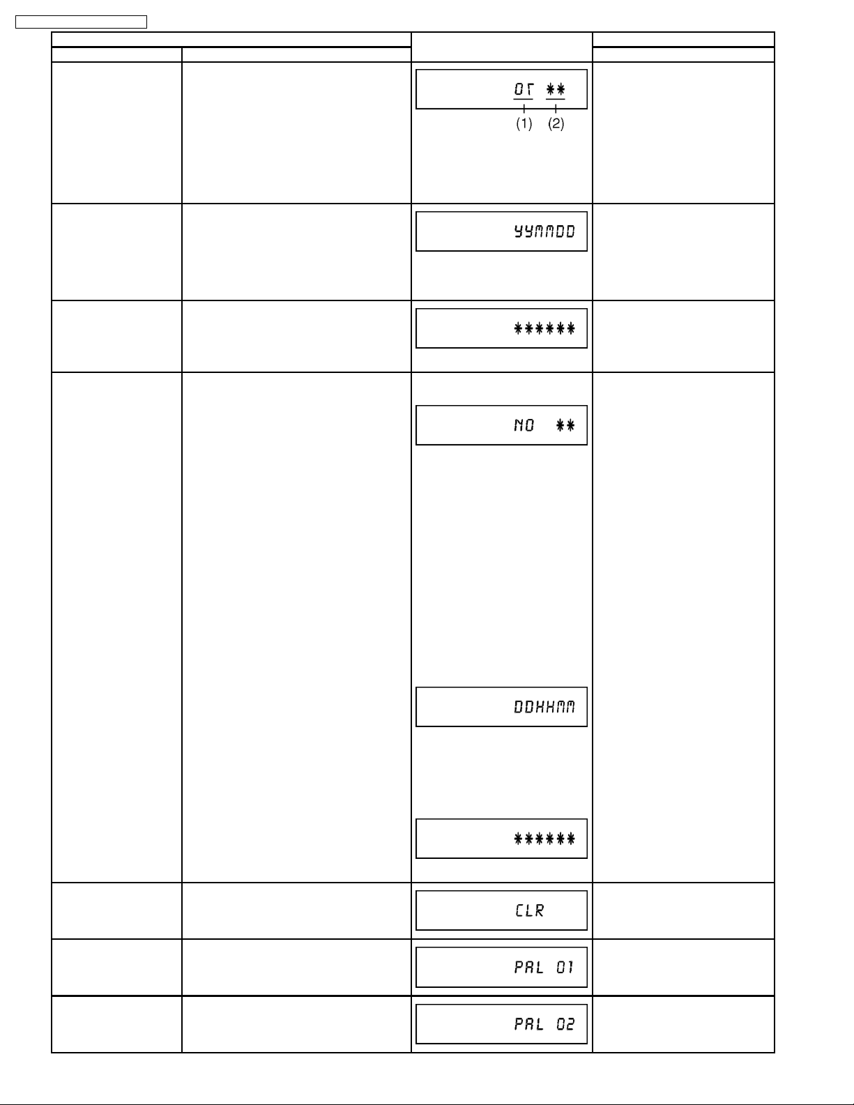
Item FL display Key operation
Mode name Description (Remote controller key)
Front connection
inspection
Press all front keys and check the
connection between Main P.C.B. and Front
key Switches.
(1) Each time a key is pressed,
segment turned on increases one
by one.
(2) Total umber of keys that have
been pressed.
Production Date Display Display the date when the unit was produced.
YY: Year
MM: Month
DD: Day
Display the accumlated
Display the accumulated unit´s working time.
working time
(Indicating unit: Second)
Display the Error History Display the Error History stored on the unit. Display reason of error for
5 seconds.
Press [5] [4] in service mode.
Press [6] [1] in service mode.
Press [6] [4] in service mode.
Press [6] [5] in service mode.
Then press [0] [1] ~ [1] [9], the
past 19 error histories are
displayed.
01:
Defect of Digital P.C.B.
(AV DEC / MAIN CPU)
02:
Defect of RAM Drive.
03:
Defect of Disc.
04:
Defect of Digital P.C.B. or
Communication Error.
05:
Defect of Digital P.C.B.
(AV DEC / MAIN CPU)
06:
Defect of HDD.
Display the time when the error
has occurred for 5 seconds.
DD: Day
hh: Hour
mm: Minute
Accumulated working time till
occuring of the error is left
displayed.
Delete the Error History Delete Error History information stored on
the unit.
AV4(V)/AV1(RGB) I/O
Setting
AV2(Y/C)/AV1(V) I/O
Setting
Set input to AV4 (V) and set output to AV1
(RGB) for I/O checking
Set input to AV2 (Y/C) and set output to
AV1 (V) for I/O checking
(Indicating unit: Second)
Press [9] [7] in service mode.
Press [8] [0] in service mode.
Press [8] [1] in service mode.
26
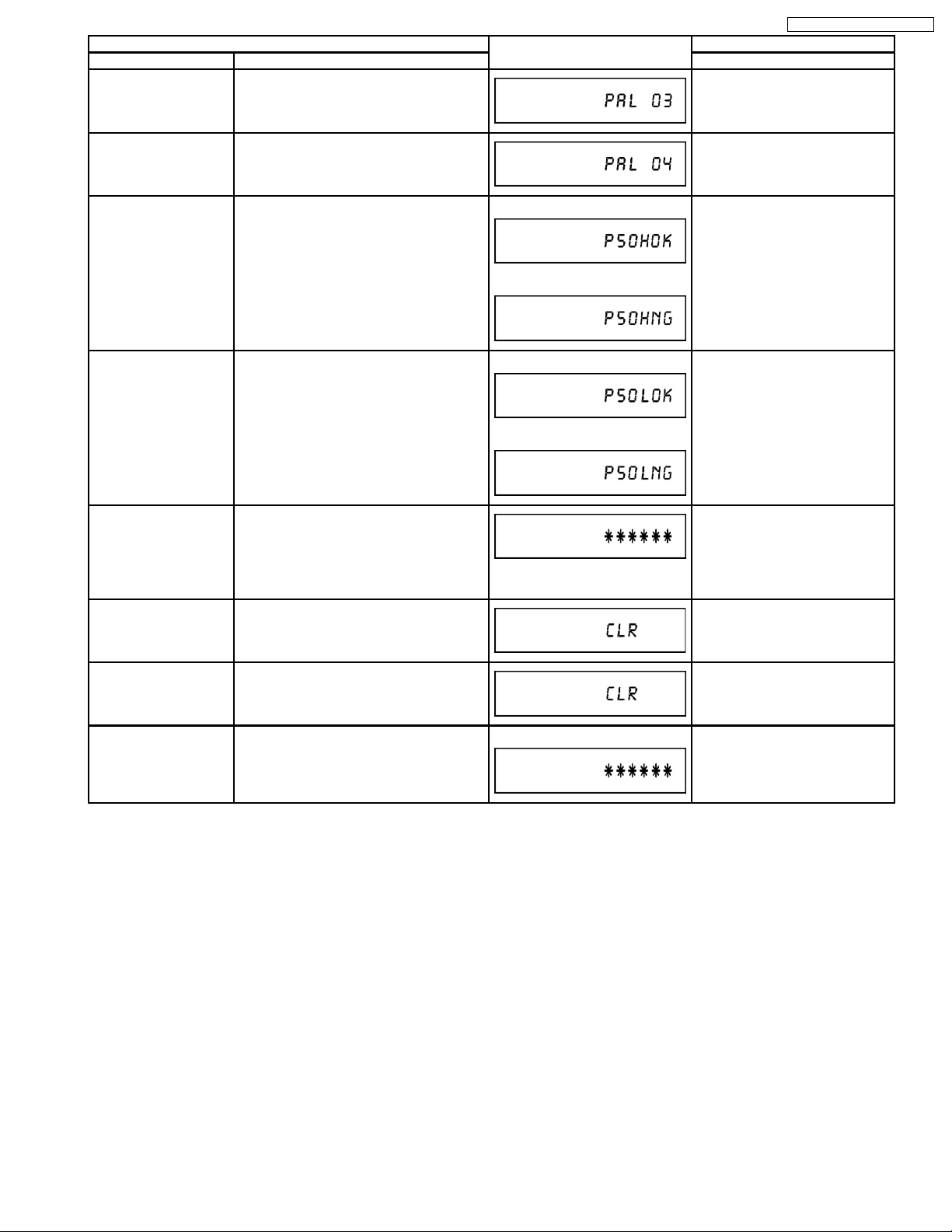
Item FL display Key operation
Mode name Description (Remote controller key)
AV2(V)/AV1(Y/C) I/O
Setting
Set input to AV2 (V) and set output to AV1
(Y/C) for I/O checking
Press [8] [2] in service mode.
DMR-ES35VEG / DMR-ES35VEC
AV2(RGB)/AV1(V) I/O
Setting
Set input to AV2 (RGB) and set output to
AV1 (V) for I/O checking
P50(H) Output Timer Microprocessor IC7504-76 output
High signal for AV1-pin 10 passing through
inverter (approx. 0V DC at AV1-pin 10).
P50(L) Output Timer Microprocessor IC7504-76 output Low
signal for AV1-pin 10 passing through
inverter (approx. 4.4V DC at AV1-pin 10).
Tray OPEN/CLOSE Test The RAM drive tray is opened and closed
repeatedly.
Error code initialization Initialization of the last error code held by
timer (Write in F00)
When OK.
When NG.
When OK.
When NG.
“*” is number of open/close cycle
times.
Press [8] [3] in service mode.
Press [8] [4] in service mode.
Press [8] [5] in service mode.
Press [9] [1] in service mode
*When releasing this mode, press
the [POWER] button of Remote
Controller more than 10 seconds.
Press [9] [8] in service mode.
Initialize Service Last Drive Error, Error history and Error
Press [9] [9] in service mode.
Codes stored on the unit are initialized to
factory setting.
Finishing service mode Release Service Mode. Display in STOP (E-E) mode. Press power button on the front
panel or Remote controller in
service mode.
27
DMR-ES35VEG / DMR-ES35VEC
8.2. (VHS) SELF-DIAGNOSIS AND SPECIAL MODE SETTING
8.2.1. (VHS) SPECIAL MODES SETTING
Item FL display Key operation
Mode name Description Front Key
Tracking Center Tape Tracking is adj usted to center
FIX position.
VHS Service Mode In order to make service easy, a part of
inside information of a microprocessor
is displayed on FIP.
*Details are described in
"13.2. VHS Service Mode".
No display. During PLAYBACK, press [VHS CH
UP] and [VHS CH DOWN] keys
simultaneously.
Press [STOP], and [EJECT] keys
simultaneously for three seconds
when power is off.
Set Drive to VHS.
Releasing EXT LINK &
Timer Program
Eject Ejecting Cassette Tape No display. While in other than Timer REC
Releasing Continuation EXT LINK &
Continuation Timer Program
No display. While in EXT LINK or Timer REC
mode, press [VHS STOP] key for 3
seconds.
mode, press [STOP] key for 3
seconds or press [STOP] key of the
Remote Controller for 3 seconds in
VHS mode.
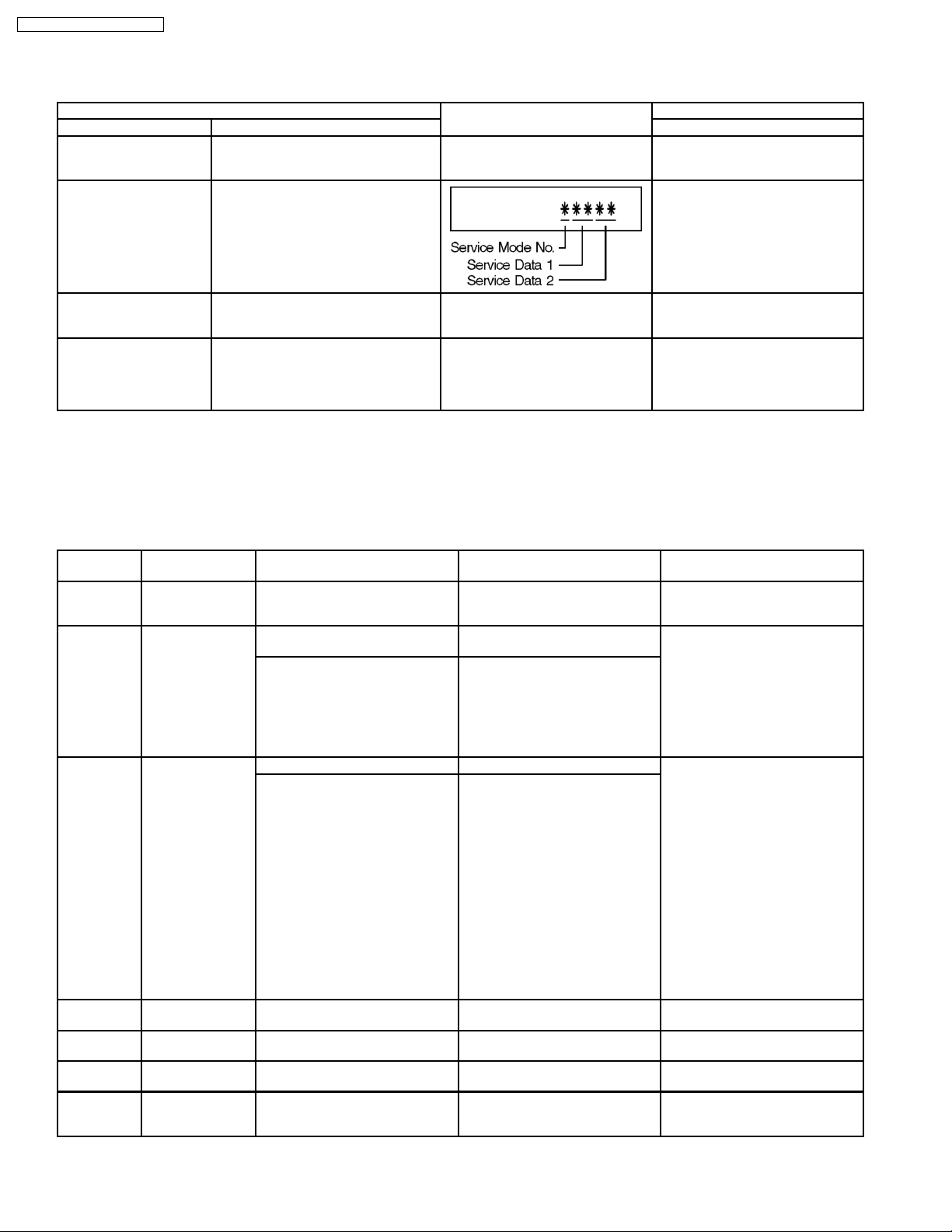
8.2.2. (VHS) SERVICE MODES
(Service Mode Setting)
1. When power is OFF, press [STOP] and [EJECT] keys simultaneously for 3 seconds to into Service Mode and
set Drive to VHS.
2. In Service Mode, press [STOP] and [EJECT] keys simultaneously to add Service Number.
Service Mode
Number
0 Indication for the
1 Indication for the
2 Indication for the
3 Self-diagnosis
4 Self-diagnosis
5 Self-diagnosis
6 Indication for the
Contents Contents of Indication on minute Contents of Indication on second Remarks
inner data of
IC6001
inner data of
IC6001
inner data of
IC6001
history (1st)
history (2nd)
history (3rd)
inner data of
IC6001
VHS mode
(Real time)
Tape beginning and ending
detection data (Real time)
00: Both tape beginning and
ending have not been detected
01: Tape ending is detecting now
02: Tape beginning is detecting
now
03: Both tape beginning and
ending are detecting now
Mechanism position (Real time) Ordering for the Motors (Real time) The following functions are
0L: EJECT position
02: DOWN position
03: RREW position
04: LOAD position
05: REV position
06: PLAY position
07: POFF position
08: STOP_R position
09: STOP_F position
0- : FF/REW position
0_ : Intermediate between each
positions
1st history of error number "- -" is displayed.
2nd history of error number "- -" is displayed
3rd history of error number "- -" is displayed
Servo data (4 digits)
(Real time)
Process number of the mechanism
movement
(Real time)
Key code
(Real time)
Indicate the receiving code when
the key of VCR or remote
controller being operated.
0*, 2*: CYL off,
CAP off
1*: CYL off,
CAP on (fwd)
3*: CYL off,
CAPon (rev)
8*, A*: CYL on,
CAP off
9*: CYL on,
CAPon (fwd)
B*: CYL on,
CAP on (rev)
*0: Motor off
*1:Loading
*2: Unloading
*3: Break (Load + Unload)
prohibited to operate the
mechanism without cassette tape.
●Tape beginning and ending
detection.
●Reel lock detection
●Tape detection and tape position
detection
Press the EJET key for over 3
seconds in this mode, and then the
VCR is shifted into the special
modes, such as PG Adjustment,
Model Code Setting, and so on.
The orders for the motors are
asfollows.
28
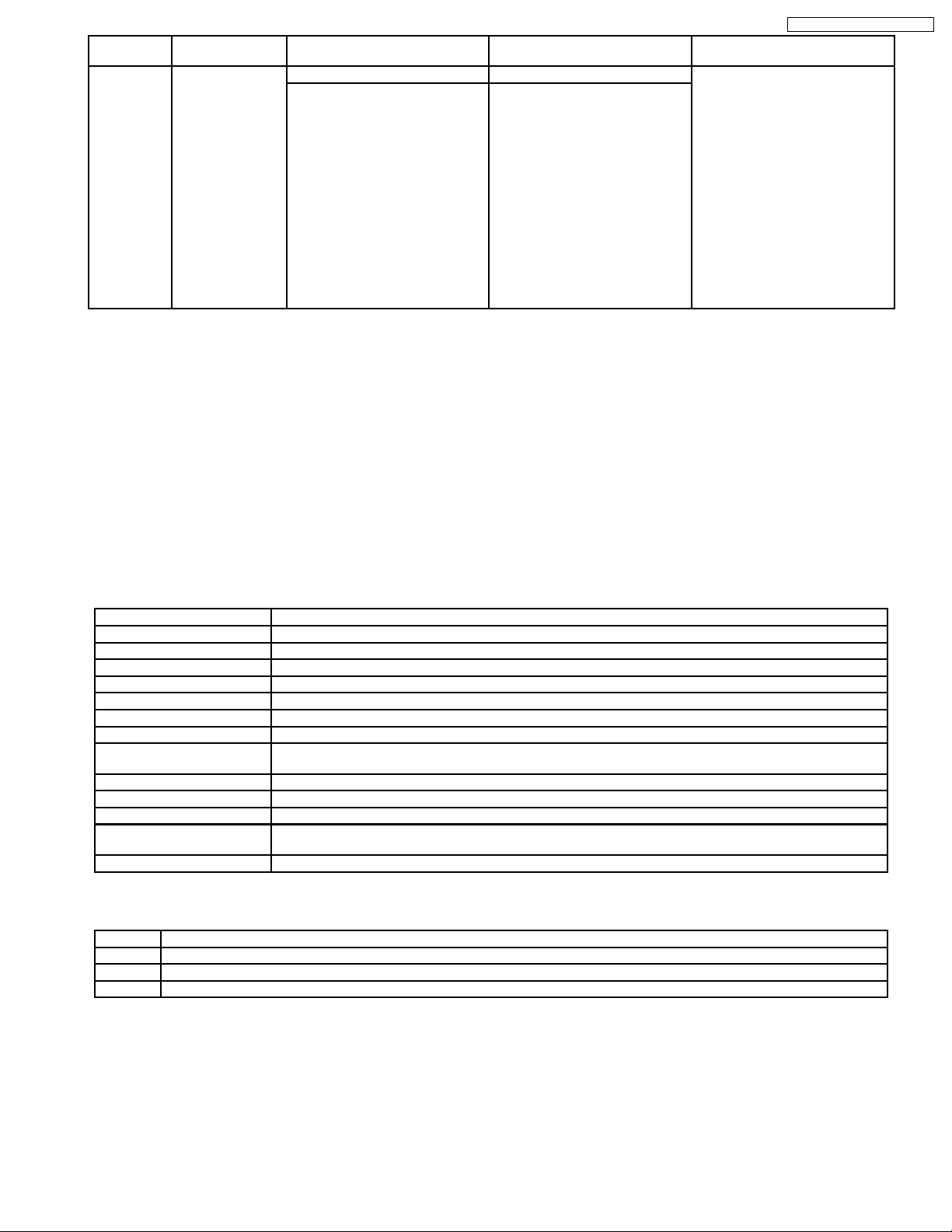
DMR-ES35VEG / DMR-ES35VEC
Service Mode
Number
7 Manual mechanism
Contents Contents of Indication on minute Contents of Indication on second Remarks
operation
Mechanism position (Real time) Ordering for the Motors Press the following key;
0L: EJECT position
02: DOWN position
03: RREW position
04: LOAD position
05: REV position
06: PLAY position
07: POFF position
08: STOP_R position
09: STOP_F position
0- : FF/REW position
0 _: Intermediate between each
positions
0*, 2*: CYL off,
CAP off
1*:CYL off,
CAP on (fwd)
3*: CYL off,
CAPon (rev)
8*, A*: CYL on,
CAP off
9*: CYL on,
CAPon (fwd)
B*: CYL on,
CAP on (rev)
*0: Motor off
*1:Loading
*2: Unloading
*3: Break (Load + Unload)
PLAY key: Loading
STOP key: Unloading
8.2.3. (VHS) SELF-DIAGNOSIS FUNCTIONS
This model has a self-diagnosis. If the VHS section detects trouble during installation or during use, the power is automatically
turned off or become power-save mode and it is memorized into the EEPROM (IC9705) as error code of two-digit number. It エs
memorized error code can be displayed in "second" display portion (the last 2 digits of the FIP) by placing the unit is Service Mode
Number 2 when turning on the Service Information Display as for example "01" or "02" etc. as below. If a second error occurs, the
most recent error will be memorized and can be displayed in Service Mode Number 2. It can be memorized until 3 self-diagnosis
histories in maximum.
In order to erase the memorized error code, press STOP and EJECT buttons on the Front Panel simultaneously over 5 seconds
during turning on Service Information Display mode.
8.2.3.1. MEMORY OF THE SELF-DIAGNOSIS HISTORY
*This is effective only in Service Mode 3, 4, 5.
8.2.3.1.1. ERROR NUMBERS AT A GLANCE
Memory No. (Error Code) Reason
01 The cylinder could not be started. (Error of the cylinder or the cylinder driver.)
02 The CAP FG could not be detected.
03 Mechanism lock during without the unloading and the cassette-up.
04 Mechanism lock during unloading
05 S-reel pulse cannot be detected during unloading. (Error of the S-reel circuit or the Capstan circuit)
06 Mechanism lock during the Cassette-up.
09 Communication error between VHS Microprocessor (IC6001) and Timer Microprocessor (IC9704).
15 S-reel pulse cannot be detected when a cassette tape is inserted.
16 Detection of the Cylinder lock during the constant rotation
17 Detection of S-reel lock during the constant tape running
18 Detection of T-reel lock during the constant tape running
2*
Refer to following table
80 An exceptional ejection depends on a accidental error
Note:
2* is as follows.
20 NG1 in the PG Shifter Automatic Adjustment (The cylinder rotation is unstable during the automatic adjustment.)
21 NG2 in the PG Shifter Automatic Adjustment (The vertical sync signal is lacked while over 5 seconds on the alignment tape.)
22 NG3 in the PG Shifter Automatic Adjustment (The installing position of Heads to the cylinder is our of specification.
23 NG4 in the PG Shifter Automatic Adjustment (The servo is not locked to the cylinder for more than 10 sec.)
(Error of the S-reel circuit or the Capstan circuit)
An error while the PG Automatic Adjustment
8.2.3.1.2. MEMORY FOR THE SELF-DIAGNOSIS HISTORY
3. The self-diagnosis result is memorized the state of the moment of detecting.
4. There are the histories from number 1 to number 3.
5. The latest error is memorized on history number 1, and then the old histories are shifted to the history number 2 and 3.
The error code memorized in the history number 2 and 3 is over-written by shift.
4. If the latest error is the same with the history number 1 (2nd-latest), it is not memorized.
(The same error code is not memorized in succession)
29
DMR-ES35VEG / DMR-ES35VEC
8.2.3.1.3. CLEAR FOR THE SELF-DIAGNOSIS HISTORY
1. Press STOP and EJECT buttons simultaneously over 5 seconds during turning on Service Information Display mode.
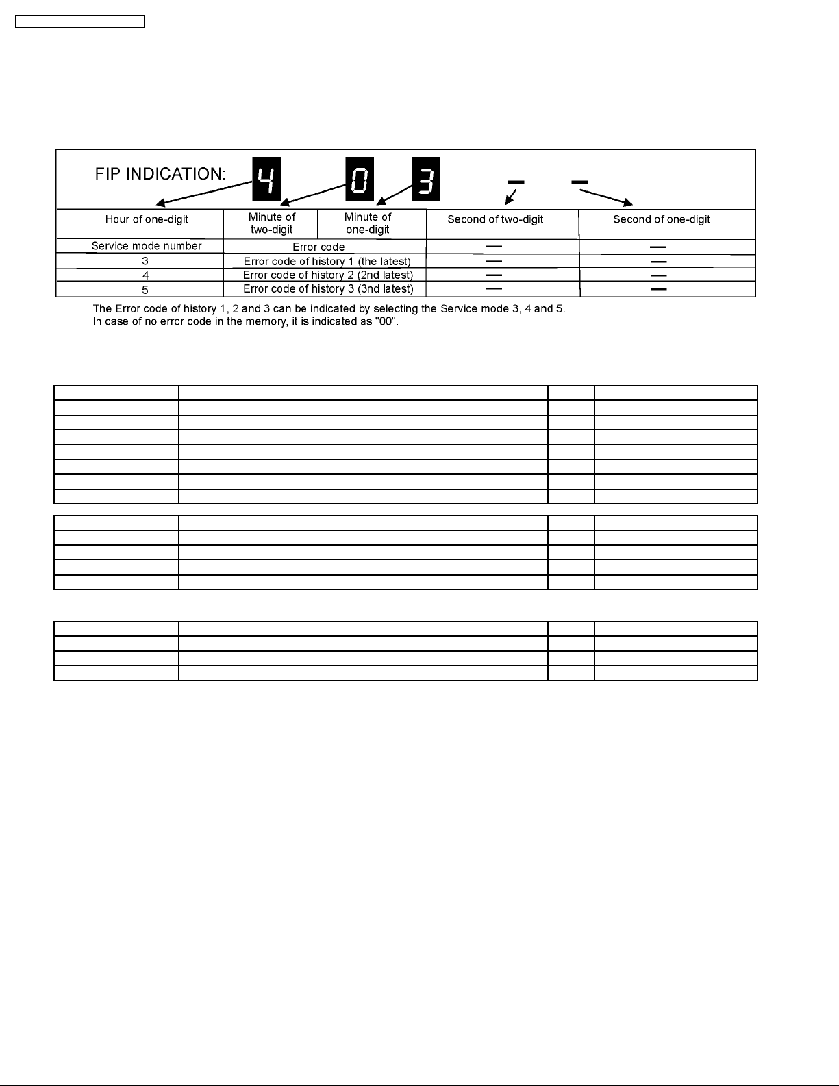
8.2.3.1.4. INDICATION OF THE SELF-DIAGNOSIS HISTORY
The self-diagnosis histories can be indicated on the FIP with Service Mode number 3 to 5.
The procedure of service mode setting and indication format are the same as usual.
9 SERVICE FIXTURE AND TOOLS
Part Number Description Pcs Compatibility
RFKZ03D01K Lead Free Solder (0.3 mm / 100 g Reel) 1 Same as ES15
RFKZ06D01K Lead Free Solder (O.6 mm / 100 g Reel) 1 Same as ES15
RFKZ010D01 Lead Free Solder (1.0 mm / 100 g Reel) 1 Same as ES15
RFKZ0316 Solder Remover (Lead free 10 W temperature Solder / 180 g) 1 Same as ES15
RFKZ0328 Flux 1 Same as ES15
RFKZ0329 Bottle of Flux 1 Same as ES15
JZS0484 Eject Pin 1 Same as ES15
Part Number Description Pcs Compatibility
RFKZ0240 Extension Cable (Main P.C.B. - Power & Digital I/F P.C.B. / 19 pin) 1 Same as E75V
RFKZ0327 Extension Cable (Main P.C.B. - Power & Digital I/F P.C.B. / 15 pin) 2 New
RFKZ0365 Extension Cable (Power Digital I/F P.C.B. - Digital P.C.B. / 64 pin) 1 New
RFKZ0239 Extension Cable (to Front Jack P.C.B. and FL P.C.B. / 10 pin) 4 Same as E75V
(for VHS)
Part Number Description Pcs Compatibility
VFJ8125H3F PAL VHS Alignment Tape 1 Same as E75V
VFK0329 Post Adjustment Screwdriver 1 Same as E75V
VFK0330 Fine Adjustment Gear Driver 1 Same as E75V
30
 Loading...