

Page 1
DMR-ES10-EB_QSG-1.fm 1 ページ 2005年3月1日 火曜日 午後1時16分
Quick Setup
DVD Recorder
Guide
Model No.
(Model suffix: “EB” for UK model, “EBL” for Ireland model)
DMR-ES10EB/EBL
Dear customer
Thank you for purchasing this product. Please use this Quick Setup Guide to help you set up your unit.
We would also advise you to carefully study the operating instructions and note the listed precautions before use.
■ Sales and Support Information
Customer Care Centre
• For customers within the UK: 08705 357357
• For customers within the Republic of Ireland: 01 289 8333
• Visit our website for product information
• E-mail: customer.care@panasonic.co.uk
Direct Sales at Panasonic UK
• Order accessory and consumable items for your product with
ease and confidence by phoning our Customer Care Centre
Monday-Thursday 9:00am-5:30pm, Friday 9:30am-5:30pm
(Excluding public holidays).
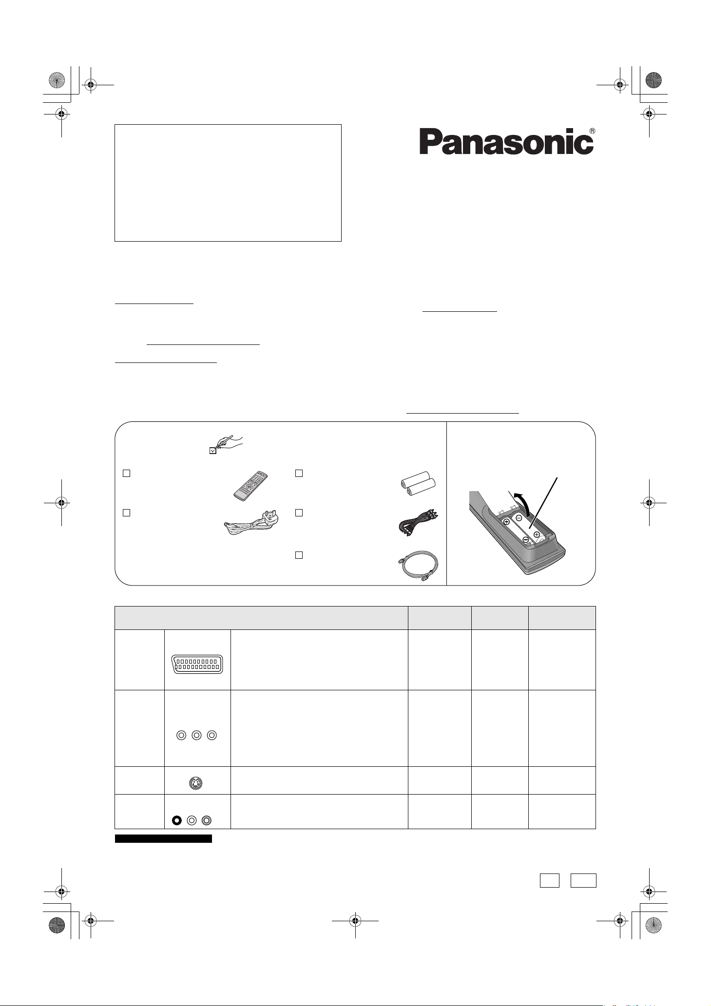
Accessories
1 Remote control
(EUR7720KM0)
Please check and identify the supplied accessories.
Use numbers when asking for replacement parts.
(Product numbers correct as of January 2005. These
may be subject to change.)
2 Batteries
R6 Size
for remote control
• Or go on line through our Internet Accessory ordering
application at www.panasonic.co.uk
• Most major credit and debit cards accepted.
• All enquiries transactions and distribution facilities are provided
directly by Panasonic UK Ltd.
• It couldn’t be simpler!
• Also available through our Internet is direct shopping for a wide
range of finished products, take a browse on our website for
further details.
Interested in purchasing an extended guarantee? Please contact
your dealer or our Customer Support Department on 01344
476540 or customer.care@panasonic.co.uk
Insert the batteries into
the remote control
.
for more details.
R6/LR6, AA
1 AC mains lead
(RJA0053-3X)
1 Audio/video cable
(K2KA6CA00001)
• For use with this unit only.
Do not use it with other equipment.
Also do not use the cords for other
equipment with this unit.
1 RF coaxial lead
(K1TWACC00001)
■ Recommended connection for your television
What kind of input terminal does your television have? Required
Scart Highly recommended connection.
AV IN
• You can enjoy high-quality RGB video from this
unit by connecting to an RGB compatible
television.
• If your television has the Q Link feature, you can
use a variety of useful functions.
Component
video
COMPONENT
VIDEO IN
S Video This terminal achieves a more vivid picture than
S-VIDEO IN
These terminals provide a purer picture than the
S Video terminal.
• If your television is compatible with progressive
scan, you can enjoy high-quality progressive
video.
If you have a progressive compatible CRT
television, we cannot recommend this
connection as some flickering may occur.
the video terminal.
cable(s)
Fully wired 21pin Scart lead
3 video cables ➔ 3 ➔ 6
S Video cable ➔ 3 ➔ 6
Page No. for
connections
➔ 2
Page No. for TV
settings
➔ 6
• If it’s a Q Link
television ➔ 5
Audio/Video The most basic connection.
For the United Kingdom only
If your television does not have one of the terminals mentioned above, connect with the RF sockets only (➔ page 4). However, when using
this connection, picture received from a satellite receiver may not be clear, therefore we do not recommend it.
RQCA1353-1
H0205HM1025
AUDIO IN
R L
VIDEO IN
- 1 -
Audio/Video
cable (included)
➔ 3 ➔ 6
EB EBL
Page 2
DMR-ES10-EB_QSG-1.fm 2 ページ 2005年2月28日 月曜日 午後1時17分
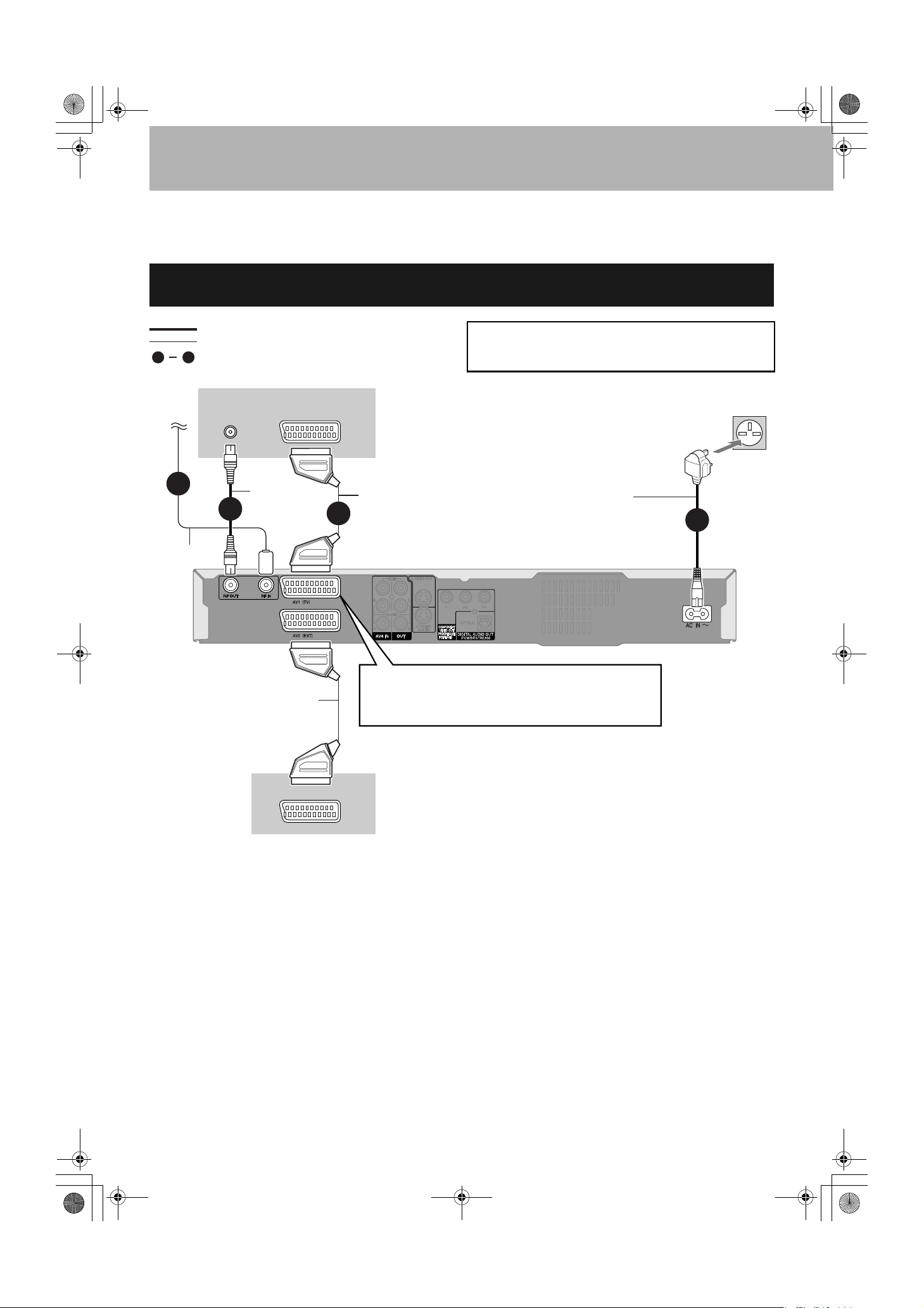
STEP 1 Connection
• The equipment connections described are examples.
• Before connection, turn off all equipment and read the appropriate operating instructions.
• Peripheral equipment and optional cables are sold separately unless otherwise indicated.
Connecting a television with 21-pin Scart terminal and Satellite/Digital
terrestrial receiver
indicates included accessories.
indicates accessories not included.
1
To th e
aerial
Aerial lead
Fully wired 21-pin Scart lead
(For External Link functions)
are required connections. Connect in the numbered order.
4
Television’s rear panel
VHF/UHF
RF IN
1
2
RF coaxial
lead
AV IN
BE SURE TO READ THE CAUTION FOR THE AC MAINS
LEAD ON PAGE 2 IN THE OPERATING INSTRUCTIONS
BEFORE CONNECTION.
Fully wired 21-pin Scart lead
(For Q Link functions)
3
AC mains lead
Connect only after all other
connections are complete.
AV1 terminal
If your television is equipped with RGB input capability, by
connecting with a fully wired 21-pin Scart lead you can see
video using RGB output on this unit (➔ below).
To household mains socket
(AC 220-240 V, 50 Hz)
4
This unit’s rear panel
DVD/VCR
Satellite/Digital terrestrial receiver’s rear panel
■ To view satellite/digital terrestrial programmes
•
Change the “AV2 Input” setting to match the output from a satellite/digital terrestrial receiver in the SETUP menu (➔ page 36 of Operating
Instructions) after tuning is completed (➔ page 5, 6).
• Press [INPUT SELECT] to select the input channel “A2” for the satellite/digital terrestrial receiver or put this unit in standby mode.
To record programmes from satellite receiver using “Sky Personal Planner” function ➔ page 21 of Operating Instructions
■ RGB
This refers to the three primary colours of light, red (R), green (G), and blue (B) and also the method of producing video that uses them. By
dividing the video signal into the three colours for transmission, noise is reduced for even higher quality images.
To record programmes from satellite receiver by RGB signals ➔ page 21 of Operating Instructions
- 2 -
Page 3

DMR-ES10-EB_QSG-1.fm 3 ページ 2005年2月28日 月曜日 午後1時17分
Connecting a television with AUDIO/VIDEO terminals and VCR
indicates included accessories.
indicates accessories not included.
1
are required connections. Connect in the numbered order.
4
To the aerial
Television’s rear panel
Splitter
Aerial
lead
1
Use a splitter if you
also want to connect
the aerial to your VCR.
VHF/UHF
RF IN
2
VHF/UHF
RF IN
RF coaxial lead
Audio/Video cable
Red White Yellow
R L
AUDIO OUT VIDEO OUT
BE SURE TO READ THE CAUTION FOR THE AC MAINS
LEAD ON PAGE 2 IN THE OPERATING INSTRUCTIONS
BEFORE CONNECTION.
To household mains socket
(AC 220-240 V, 50 Hz)
AUDIO IN
VIDEO IN
R L
Red White Yellow
AC mains lead
Connect only after all other
connections are complete.
Audio/Video cable
3
Yellow
White
Red
You can also connect with the AV2 terminal
on this unit using the 21-pin Scart lead.
Yellow
White
Red
VCR’s rear panel
4
This unit’s rear panel
Connecting a television with S VIDEO or COMPONENT VIDEO terminals
AUDIO IN
VIDEO
R L
IN
Red White Yellow
Audio/Video
cable
Yellow
White
Red
S VIDEO OUT terminal
Connect to S VIDEO IN terminal on the television
through a S Video cable.
The S VIDEO OUT terminal achieves a more vivid
picture than the VIDEO OUT terminal. (Actual results
depend on the television.)
■ Component video output
Component signal outputs the colour difference signals (PB/PR) and luminance signal (Y) separately in order to achieve high fidelity in
reproducing colours. If the television is compatible with progressive output, a high quality picture can be output because this unit’s
component video output terminal outputs a progressive output signal (➔ page 42 of Operating Instructions).
S VIDEO
IN
S Video cable
COMPONENT
VIDEO IN
Tel ev is ion’s
rear panel
This unit’s
rear panel
AUDIO IN
VIDEO
R L
IN
Red White Yellow
S VIDEO
IN
COMPONENT
VIDEO IN
Audio/Video cable
Yel low
White
Red
COMPONENT VIDEO OUT terminal
Connect to COMPONENT VIDEO IN terminals on the
television through a video cable. These terminals can be
used for either interlace or progressive output
(
➔ page 42 of Operating Instructions) and provide a
purer picture than the S VIDEO OUT terminal.
• Connect to terminals of the same colour.
•
Video output from the component terminal will have no
colour during EXT LINK recordings. Use a fully wired 21pin Scart lead between the TV and the unit when viewing
external equipment picture through the AV2 terminal.
(➔ page 9 of Operating Instructions, Note to owners of
progressive compatible PAL system televisions)
- 3 -
Tel ev is ion’s
rear panel
Video
cable
This unit’s
rear panel
Page 4

DMR-ES10-EB_QSG-2.fm 4 ページ 2005年2月28日 月曜日 午後1時18分
For the United Kingdom only
Connecting a television with RF socket only and Satellite/Digital
terrestrial receiver
Connect in the numbered order. If you do not have a Satellite/Digital terrestrial receiver, connect the aerial to RF IN socket of this unit
and skip step 3.
To t he
aerial
1
indicates included accessories.
indicates accessories not included.
Television’s rear panel
VHF/UHF
RF IN
2
RF coaxial lead
Aerial lead
RF IN
3
RF coaxial lead
BE SURE TO READ THE CAUTION FOR THE AC MAINS
LEAD ON PAGE 2 IN THE OPERATING INSTRUCTIONS
BEFORE CONNECTION.
To household mains socket
(AC 220-240 V, 50 Hz)
AC mains lead
Connect only after all other
connections are complete.
4
This unit’s rear panel
RF OUT
Satellite/Digital terrestrial receiver’s rear panel
- 4 -
Page 5

DMR-ES10-EB_QSG-2.fm 5 ページ 2005年2月28日 月曜日 午後1時18分
STEP 2 TV Tuning
Tuning Preset Download (Setup with Q Link functions)
When connecting to a television that has the Q Link function (➔ page 42 of Operating Instructions) with a
fully wired 21-pin Scart lead (➔ page 2).
(The AV2 and AV4 Scart terminals on Panasonic televisions are compatible with the Q Link function.)
You can download the tuning positions from the television.
This unit’s Auto Clock Setting function synchronizes the time when the TV channel that is broadcasting time and date information is
tuned.
1 Turn on the television and select the appropriate
AV input to suit the connections to this unit.
2 Press [^ DVD] to turn the unit on.
DIRECT TV REC
VOLUME
CH
AV
Tuning Preset Downloading starts.
Download from TV
Pos 2
Download in progress, please wait.
RETURN: to abort
CANCEL
SKIP SLOW/SEARCH
TOP MENU
SUB MENU
PROG/CHECK
DISPLAY
REC MODE
REC
CREATE
CHAPTER
AUDIO
VIDEO Plus+
INPUT SELECT
MANUAL SKIP
FUNCTIONSDIRECT NAVIGATOR
RETURN
STATUS
TIME SLIP
EXT LINK
TIMER
ERASE
F Rec
RETURN
3 When tuning preset downloading has completed, the Owner ID settings
screen appears.
Press [q] and press the numbered buttons to
enter a 4-digit PIN number.
Owner ID
PIN number
Name
House No.
RETURN
Postcode
RETURN : leave
• Make a note of the PIN number (don’t forget), as it is not possible to return to
the factory preset.
4 Press [ENTER] twice to store the PIN number.
The cursor moves to “Name”.
5 Press [q].
6 Press [e, r] to select a letter and then press [q].
Repeat this to enter the name.
7 Press [ENTER] to store the name.
8 Press [r] and [q], and then repeat step 6, 7 to
enter and store “House No.” and “Postcode”.
9 Press [RETURN].
The Owner ID settings screen disappears.
To st op par t way
Press [RETURN].
■ If the clock setting menu appears
Set the clock manually (➔ page 40 of Operating Instructions).
■ To confirm that stations have been tuned correctly (➔ page 38 of Operating Instructions)
■ To restart Tuning Preset Download (➔ page 39 of Operating Instructions)
■ If you connect other equipment to AV2 terminal of this unit
Change the “AV2 Input” in the SETUP menu to match the connected equipment (➔ page 36 of Operating Instructions).
For the United Kingdom only
■ If there is interference or a very poor picture appears on the TV screen
Refer to “Removing Interference” on page 13 of Operating Instructions, and perform steps 1, 2 and 4 to stop the RF output. In step 2,
press [0] to select “– –”.
- 5 -
Page 6

DMR-ES10-EB_QSG-1.fm 6 ページ 2005年2月28日 月曜日 午後1時17分
Auto-Setup (Setup without Q Link functions)
•
When connecting to a television with the VIDEO OUT, S VIDEO OUT or COMPONENT VIDEO OUT terminal (➔page 3).
• When connecting to a television that does not have the Q Link functin (➔ page 42 of Operating Instructions).
This unit’s Auto-Setup function automatically tunes all available TV stations and synchronizes the time when the TV channel that is
broadcasting time and date information is tuned.
• When connecting to a television with RF socket only (➔ page 4).
1 Turn on the television and select the appropriate AV
input to suit the connections to this unit.
2 Press [^ DVD] to turn the unit on.
Auto-Setup starts. This takes about 5 minutes.
Auto-Setup
Ch 1
Auto-Setup in progress, please wait.
RETURN: to abort
RETURN
For the United Kingdom only
(When connecting to a television with RF socket only)
Set the new RF output channel to TV (refer to the
instructions for your TV). Select an unused channel
preset on your TV and tune it to the RF output
channel number shown on the unit’s display. (When
the Auto-Setup screen does not appear clearly even
after performing the above operations, re-tune the
channel until the Auto-Setup screen becomes clear.)
DIRECT TV REC
VOLUME
CH
AV
VIDEO Plus+
CANCEL
SKIP SLOW/SEARCH
TOP MENU
SUB MENU
PROG/CHECK
DISPLAY
REC MODE
REC
CREATE
CHAPTER
AUDIO
INPUT SELECT
MANUAL SKIP
FUNCTIONSDIRECT NAVIGATOR
RETURN
STATUS
TIME SLIP
EXT LINK
TIMER
ERASE
F Rec
3 When Auto-Setup has completed, the Owner ID settings screen appears.
Press [q] and press the numbered buttons to enter a
4-digit PIN number.
Owner ID
PIN number
Name
House No.
RETURN
Postcode
RETURN : leave
• Make a note of the PIN number (don’t forget), as it is not possible to return to the
factory preset.
4 Press [ENTER] twice to store the PIN number.
The cursor moves to “Name”.
5 Press [q].
6 Press [e, r] to select a letter and then press [q].
Repeat this to enter the name.
7 Press [ENTER] to store the name.
8 Press [r] and [q], and then repeat step 6, 7 to enter
and store “House No.” and “Postcode”.
9 Press [RETURN].
The Owner ID settings screen disappears.
To st op par t way
Press [RETURN].
■ If the clock setting menu appears
Set the clock manually (➔ page 40 of Operating Instructions).
■ To confirm that stations have been tuned correctly (➔ page 38 of Operating Instructions)
■ To restart Auto-Setup (➔ page 39 of Operating Instructions)
■ To enter the satellite station’s name (➔ page 38 of Operating Instructions)
The name of the satellite station is not set automatically. (“-- -----” will appear under “Name” in the programme list). After Auto-Setup is
completed, enter the name manually.
■ If you connect other equipment to AV2 terminal of this unit
Change the “AV2 Input” in the SETUP menu to match the connected equipment (➔ page 36 of Operating Instructions).
- 6 -
 Loading...