

Panasonic DMREH-57-GN Service manual
Model No.
Vol. 1
Colour
(S).......................Silver Type
(K).......................Black Type
ORDER NO.CHM0705024CE
DVD Recorder
© 2007 Matsushita Electric Industrial Co., Ltd. All
rights reserved. Unauthorized copying and
distribution is a violation of law.
DMR-EH57GN
CONTENTS
Page Page
1 Safety Precaution 3
1.1. General guidelines
2 Warning
2.1. Prevention of Electrostatic Discharge (ESD) to
Electrostatic Sensitive (ES) Devices
2.2. Precaution of Laser Diode
2.3. Service caution based on legal restrictions
3 Service Navigation
3.1. Service Information
3.2. Caution for DivX
4 Specifications
5 Location of Controls and Components
6 Operation Instructions
6.1. Taking out the Disc from DVD-Drive Unit when the Disc
cannot be ejected by OPEN/CLOSE button
7 Service Mode
7.1. Self-Diagnosis and Special Mode Setting
8 Service Fixture & Tools
9 Disassembly and Assembly Instructions
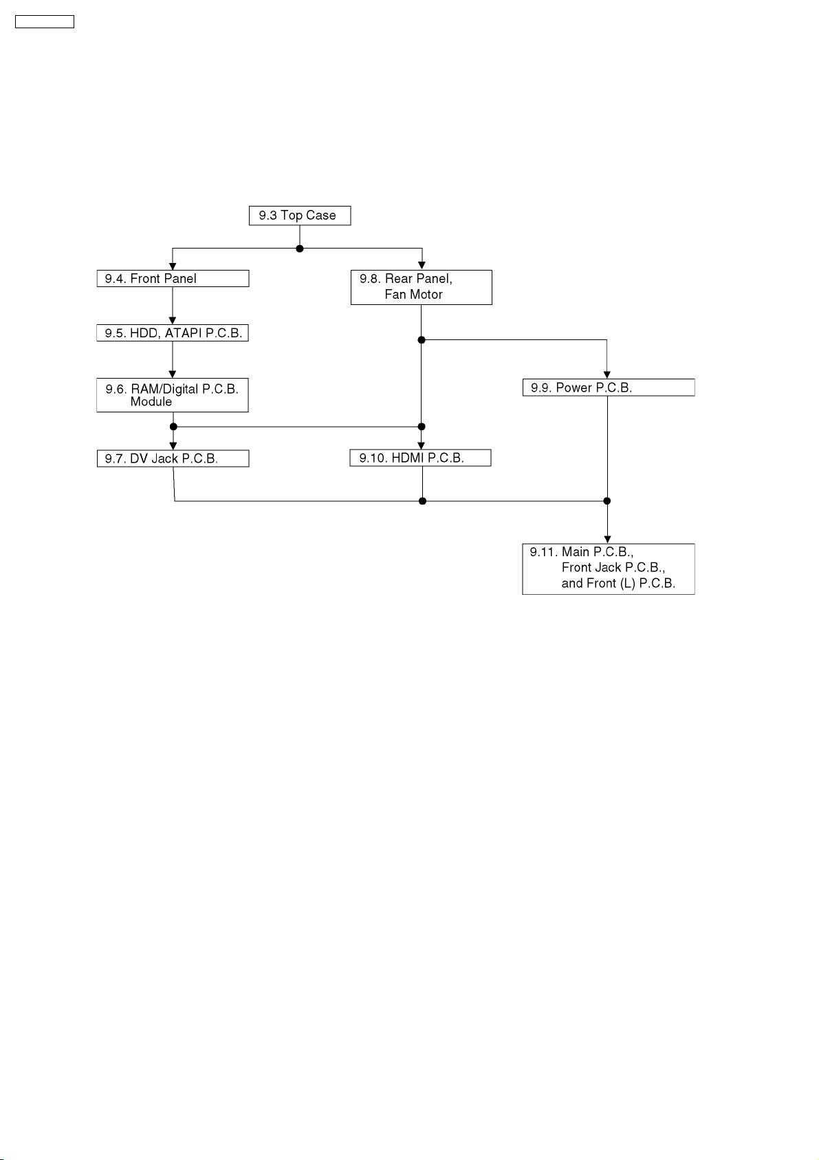
9.1. Disassembly Flow Chart
9.2. P.C.B. Positions
9.3. Top Case
9.4. Front Panel
9.5. HDD, ATAPI P.C.B.
9.6. RAM/Digital P.C.B. Module
9.7. DV Jack P.C.B.
9.8. Rear Panel
9.9. Power P.C.B.
9.10. HDMI P.C.B.
9.11. Main P.C.B., Front Jack P.C.B. and Front (L) P.C.B.
10 Measurements and Adjustments
10.1. Service Positions
10.2. Caution for Replacing Parts
10.3. Standard Inspection Specifications after Making Repairs
11 Block Diagram
11.1. Power Supply Block Diagram
11.2. Analog Video Block Diagram
11.3. Analog Audio Block Diagram
11.4. Analog Timer Block Diagram
11.5. HDMI Block Diagram
12 Schematic Diagram
12.1. Interconnection Schematic Diagram
12.2. Power Supply Schematic Diagram
10
12
12
15
15
27
28
28
29
30
30
31
33
34
34
35
35
36
37
37
41
43
45
45
47
48
49
50
51
51
52
3
4
4
5
6
7
7
7
8
12.3. Main Net (1/4) Section (Main P.C.B. (1/4)) Schematic
Diagram (M)
12.4. Main Net (2/4) Section (Main P.C.B. (1/4)) Schematic
Diagram (M)
12.5. Main Net (3/4) Section (Main P.C.B. (1/4)) Schematic
Diagram (M)
12.6. Main Net (4/4) Section (Main P.C.B. (1/4)) Schematic
Diagram (M)
12.7. AV I/O (1/4) Section (Main P.C.B. (2/4)) Schematic
Diagram (AV)
12.8. AV I/O (2/4) Section (Main P.C.B. (2/4)) Schematic
Diagram (AV)
12.9. AV I/O (3/4) Section (Main P.C.B. (2/4)) Schematic
Diagram (AV)
12.10. AV I/O (4/4) Sectio n (Main P.C.B . (2/4)) Schem atic
Diagram (AV)
12.11. Tuner Section (Main P.C.B. (3/4)) Schem atic Diagram
(TU)
12.12. Timer (1/4) Section (Main P.C.B . (4/4)) Schem atic
Diagram (T)
12.13. Timer (2/4) Section (Main P.C.B . (4/4)) Schem atic
Diagram (T)
12.14. Timer (3/4) Section (Main P.C.B . (4/4)) Schem atic
Diagram (T)
12.15. Timer (4/4) Section (Main P.C.B . (4/4)) Schem atic
Diagram (T)
12.16. HDMI Schematic Diagram
12.17. DV Jack Schematic Diagram
12.18. Front Jack Schematic Diagram
12.19. Front (L) Schematic Diagram
12.20. ATAP I Schematic Diagram
13 Printed Circuit Board
13.1. Power P.C.B. and DV Jack P.C.B.
13.2. Main P.C.B.
13.3. HDMI P.C.B.
13.4. Front Jack P.C.B. and Front (L) P.C.B.
13.5. ATAPI P.C.B.
14 Appendix for Schematic Diagram
14.1. Voltage and Waveform Chart
15 Parts and Exploded Views
15.1. Exploded Views
15.2. Replacement Parts List
53
54
55
56
58
59
60
61
63
64
65
66
67
68
69
69
69
69
71
71
72
77
78
79
81
81
88
88
90
2
DMR-EH57GN
1 Safety Precaution
1.1. General guidelines
1. When servicing, observe the original lead dress. If a short circuit is found, replace all parts which have been overheated or
damaged by the short circuit.
2. After servicing, see to it that all the protective devices such as insulation barriers, insulation papers shields are properly
installed.
3. After servicing, make the following leakage current checks to prevent the customer from being exposed to shock hazards.
1.1.1. Leakage current cold check
1. Unplug the AC cord and connect a jumper between the two
prongs on the plug.
2. Measure the resistance value, with an ohmmeter, between
the jumpered AC plug and each exposed metallic cabinet
part on the equipment such as screwheads, connectors,
control shafts, etc. When the exposed metallic part has a
return path to the chassis, the reading should be between
1MW and 5.2MW.
When the exposed metal does not have a return path to the
chassis, the reading must be
.
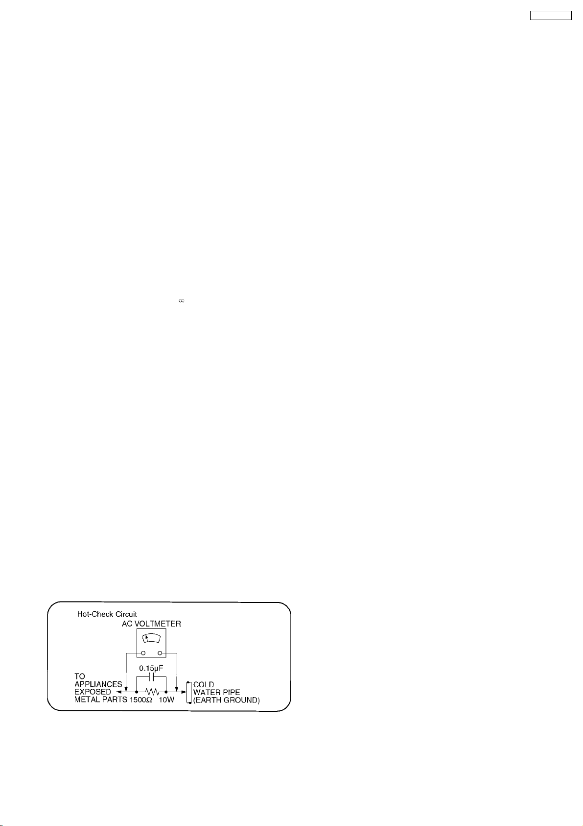
1.1.2. Leakage current hot check
(See Figure 1 .)
1. Plug the AC cord directly into the AC outlet. Do not use an
isolation transformer for this check.
2. Connect a 1.5kW, 10 watts resistor, in parallel with a 0.15µF
capacitors, between each exposed metallic part on the set
and a good earth ground such as a water pipe, as shown in
Figure 1.
3. Use an AC voltmeter, with 1000 ohms/volt or more
sensitivity, to measure the potential across the resistor.
4. Check each exposed metallic part, and measure the
voltage at each point.
5. Reverse the AC plug in the AC outlet and repeat each of the
above measurements.
6. The potential at any point should not exceed 0.75 volts
RMS. A leakage current tester (Simpson Model 229 or
equivalent) may be used to make the hot checks, leakage
current must not exceed 1/2 milliampere. In case a
measurement is outside of the limits specified, there is a
possibility of a shock hazard, and the equipment should be
repaired and rechecked before it is returned to the
customer.
Figure 1
3
DMR-EH57GN
2 Warning
2.1. Prevention of Electrostatic Discharge (ESD) to Electrostatic Sensitive
(ES) Devices
Some semiconductor (solid state) devices can be damaged easily by static electricity. Such components commonly are called
Electrostatic Sensitive (ES) Devices. Examples of typical ES devices are integrated circuits and some field-effect transistor-sand
semiconductor "chip" components. The following techniques should be used to help reduce the incidence of component damage
caused by electrostatic discharge (ESD).
1. Immediately before handling any semiconductor component or semiconductor-equipped assembly, drain off any ESD on your
body by touching a known earth ground. Alternatively, obtain and wear a commercially available discharging ESD wrist strap,
which should be removed for potential shock reasons prior to applying power to the unit under test.
2. After removing an electrical assembly equipped with ES devices, place the assembly on a conductive surface such as
aluminum foil, to prevent electrostatic charge buildup or exposure of the assembly.
3. Use only a grounded-tip soldering iron to solder or unsolder ES devices.
4. Use only an anti-static solder removal device. Some solder removal devices not classified as "anti-static (ESD protected)" can
generate electrical charge sufficient to damage ES devices.
5. Do not use freon-propelled chemicals. These can generate electrical charges sufficient to damage ES devices.
6. Do not remove a replacement ES device from its protective package until immediately before you are ready to install it. (Most
replacement ES devices are packaged with leads electrically shorted together by conductive foam, aluminum foil or comparable
conductive material).
7. Immediately before removing the protective material from the leads of a replacement ES device, touch the protective material
to the chassis or circuit assembly into which the device will be installed.
Caution
Be sure no power is applied to the chassis or circuit, and observe all other safety precautions.
8. Minimize bodily motions when handling unpackaged replacement ES devices. (Otherwise harmless motion such as the
brushing together of your clothes fabric or the lifting of your foot from a carpeted floor can generate static electricity sufficient
to damage an ES device).
4
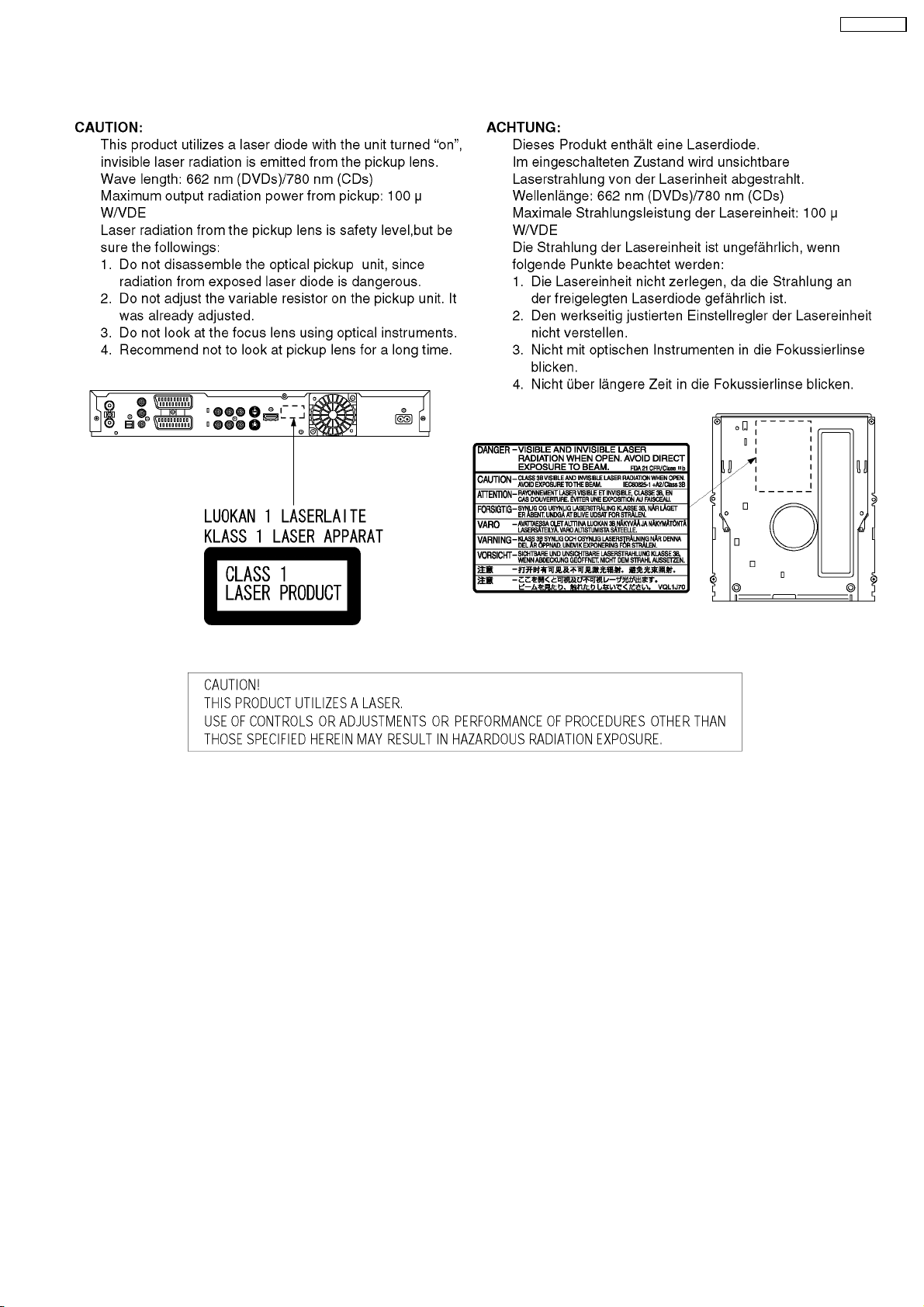
2.2. Precaution of Laser Diode
DMR-EH57GN
5

DMR-EH57GN
2.3. Service caution based on legal restrictions
2.3.1. General description about Lead Free Solder (PbF)
The lead free solder has been used in the mounting process of all electrical components on the printed circuit boards used for this
equipment in considering the globally environmental conservation.
The normal solder is the alloy of tin (Sn) and lead (Pb). On the other hand, the lead free solder is the alloy mainly consists of tin
(Sn), silver (Ag) and Copper (Cu), and the melting point of the lead free solder is higher approx.30 degrees C (86°F) more than that
of the normal solder.
Definition of PCB Lead Free Solder being used
The letter of “PbF” is printed either foil side or components side on the PCB using the lead free solder.
(See right figure)
Service caution for repair work using Lead Free Solder (PbF)
·
· The lead free solder has to be used when repairing the equipment for which the lead free solder is used.
· ·
(Definition: The letter of “PbF” is printed on the PCB using the lead free solder.)
·
· To put lead free solder, it should be well molten and mixed with the original lead free solder.
· ·
·
· Remove the remaining lead free solder on the PCB cleanly for soldering of the new IC.
· ·
·
· Since the melting point of the lead free solder is higher than that of the normal lead solder, it takes the longer time to melt
· ·
the lead free solder.
·
· Use the soldering iron (more than 70W) equipped with the temperature control after setting the temperature at 350±30
· ·
degrees C (662±86°F).
Recommended Lead Free Solder (Service Parts Route.)
·
· The following 3 types of lead free solder are available through the service parts route.
· ·
RFKZ03D01K-----------(0.3mm 100g Reel)
RFKZ06D01K-----------(0.6mm 100g Reel)
RFKZ10D01K-----------(1.0mm 100g Reel)
Note
* Ingredient: tin (Sn), 96.5%, silver (Ag) 3.0%, Copper (Cu) 0.5%, Cobalt (Co) / Germanium (Ge) 0.1 to 0.3%
6
3 Service Navigation
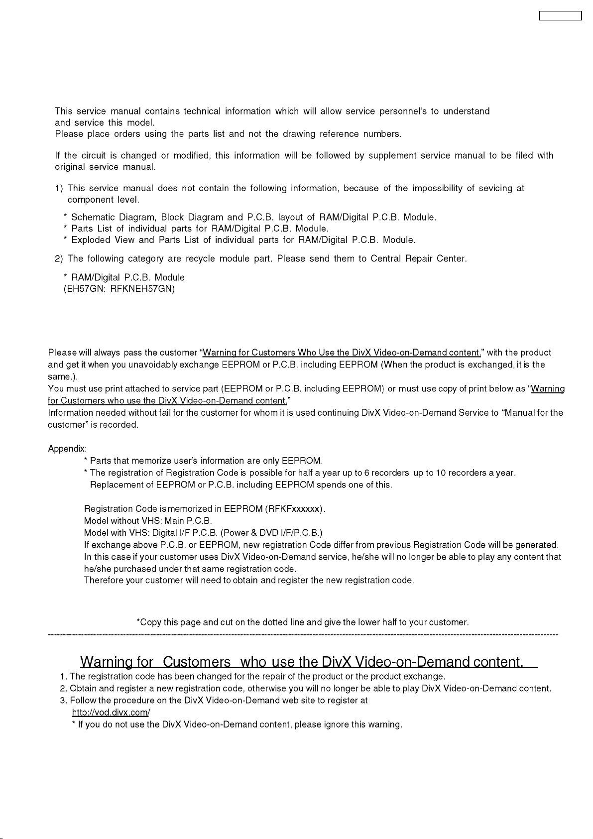
3.1. Service Information
DMR-EH57GN
3.2. Caution for DivX
7
DMR-EH57GN
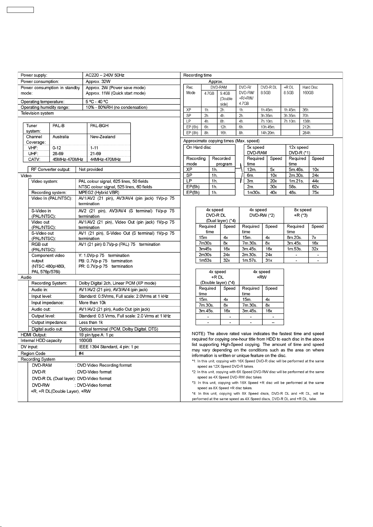
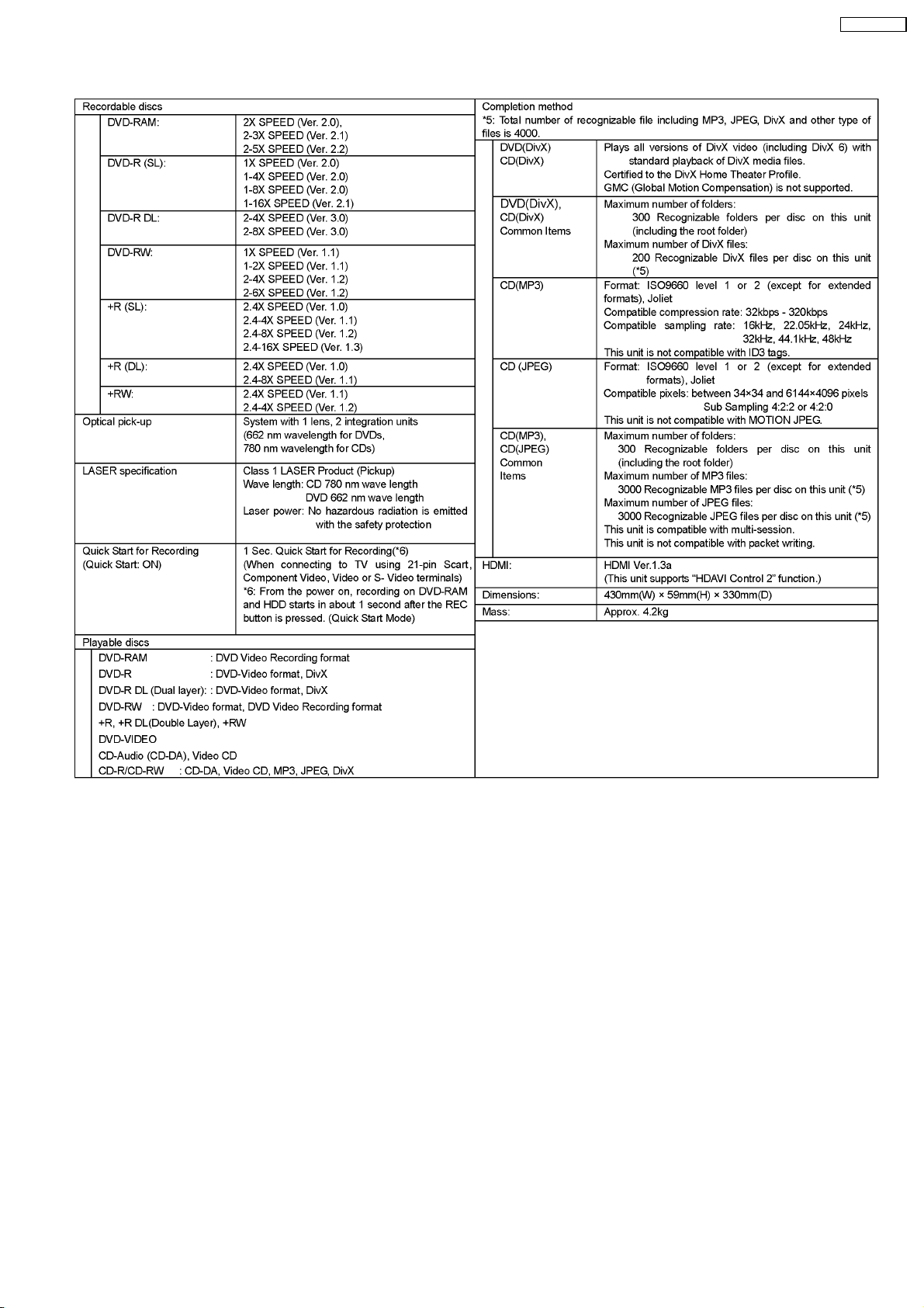
4 Specifications
8
DMR-EH57GN
9
DMR-EH57GN
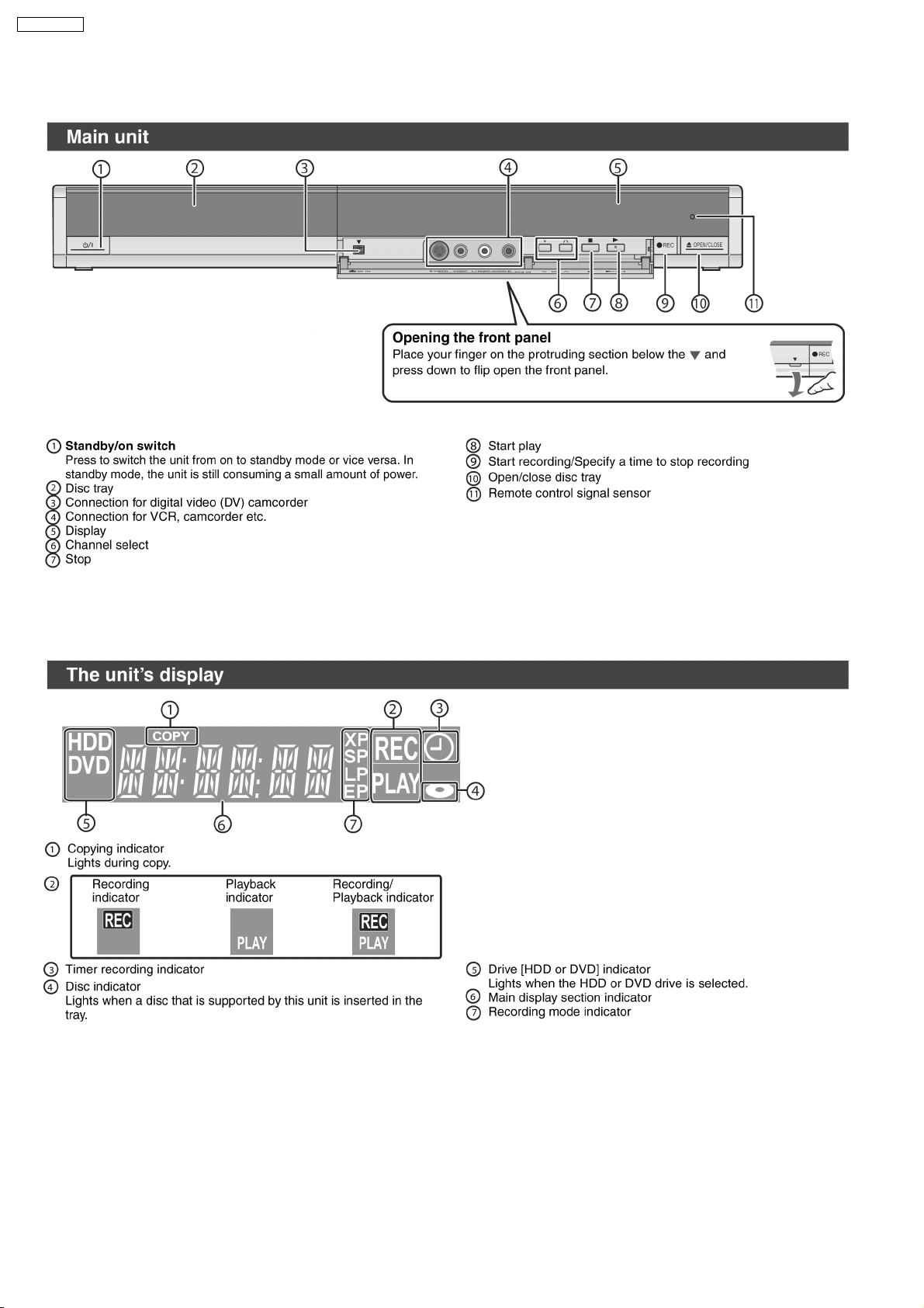
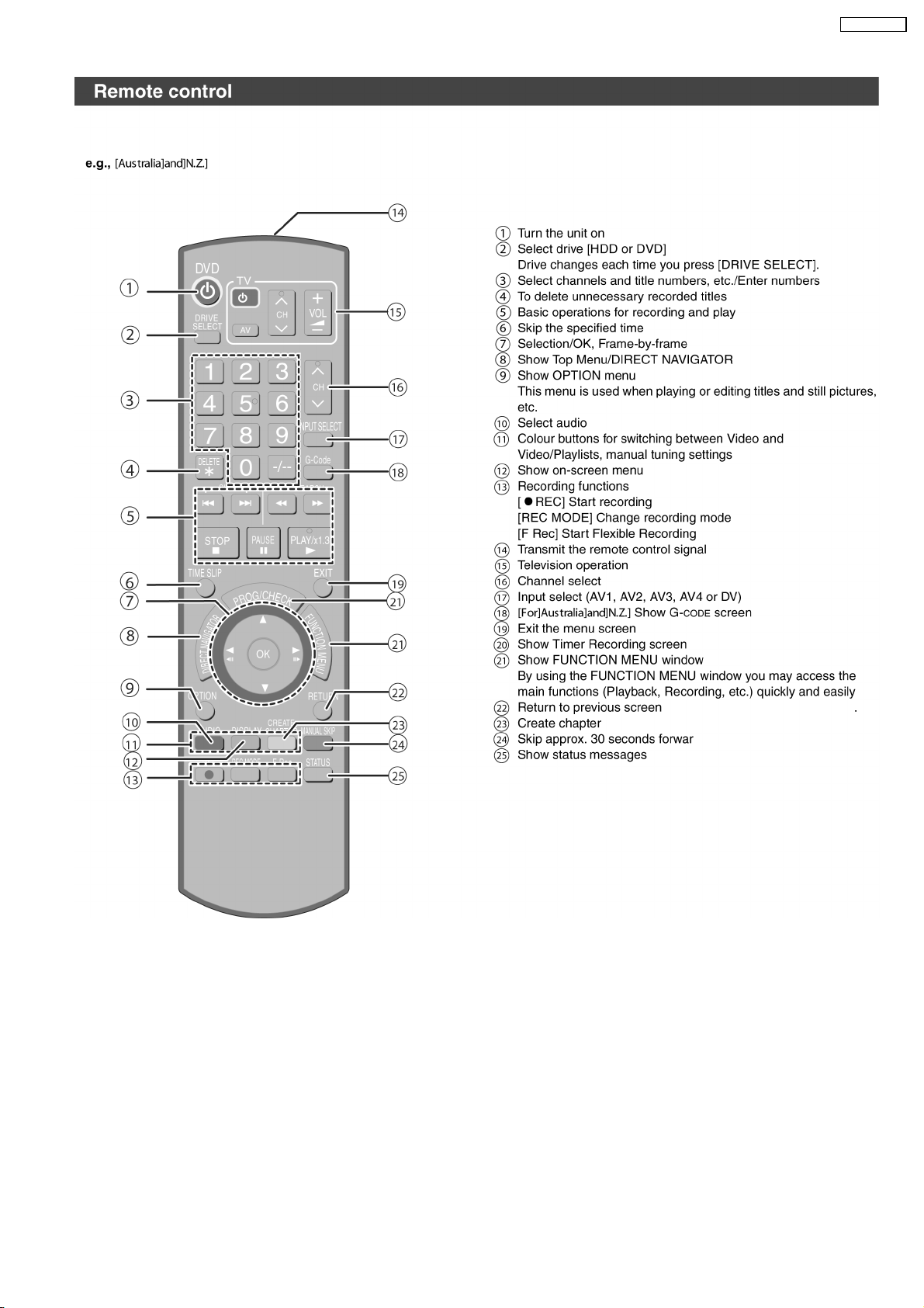
5 Location of Controls and Components
10
DMR-EH57GN
11

DMR-EH57GN
6 Operation Instructions
6.1. Taking out the Disc from DVD-Drive Unit when the Disc cannot be
ejected by OPEN/CLOSE button
6.1.1. Forcible Disc Eject
6.1.1.1. When the power can be turned off.
1. Turn off the power and press [STOP] [CH UP] keys on the front panel simultaneously for 5 seconds.
6.1.1.2. When the power can not be turned off.
1. Press [POWER] key on the front panel for over 10 seconds to turn off the power forcibly, and press [STOP] [CH UP] keys on
the front panel simultaneously for 5 seconds.
12
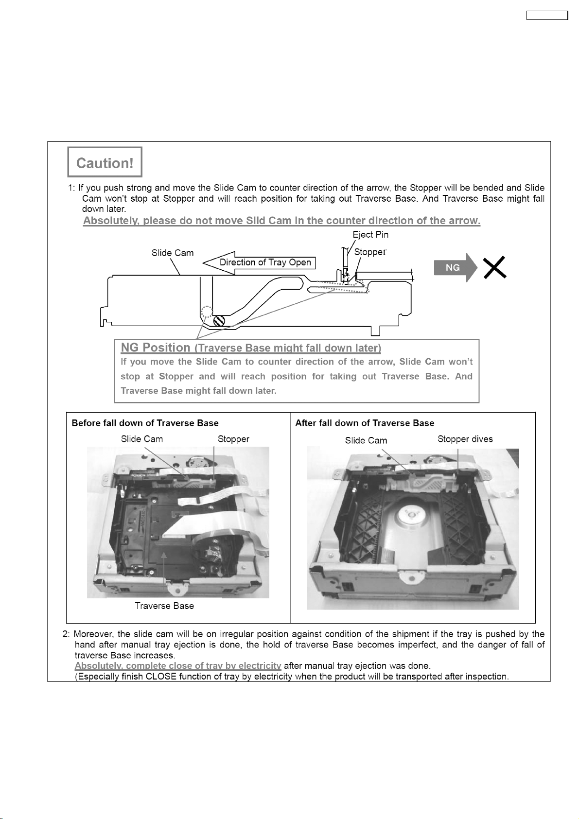
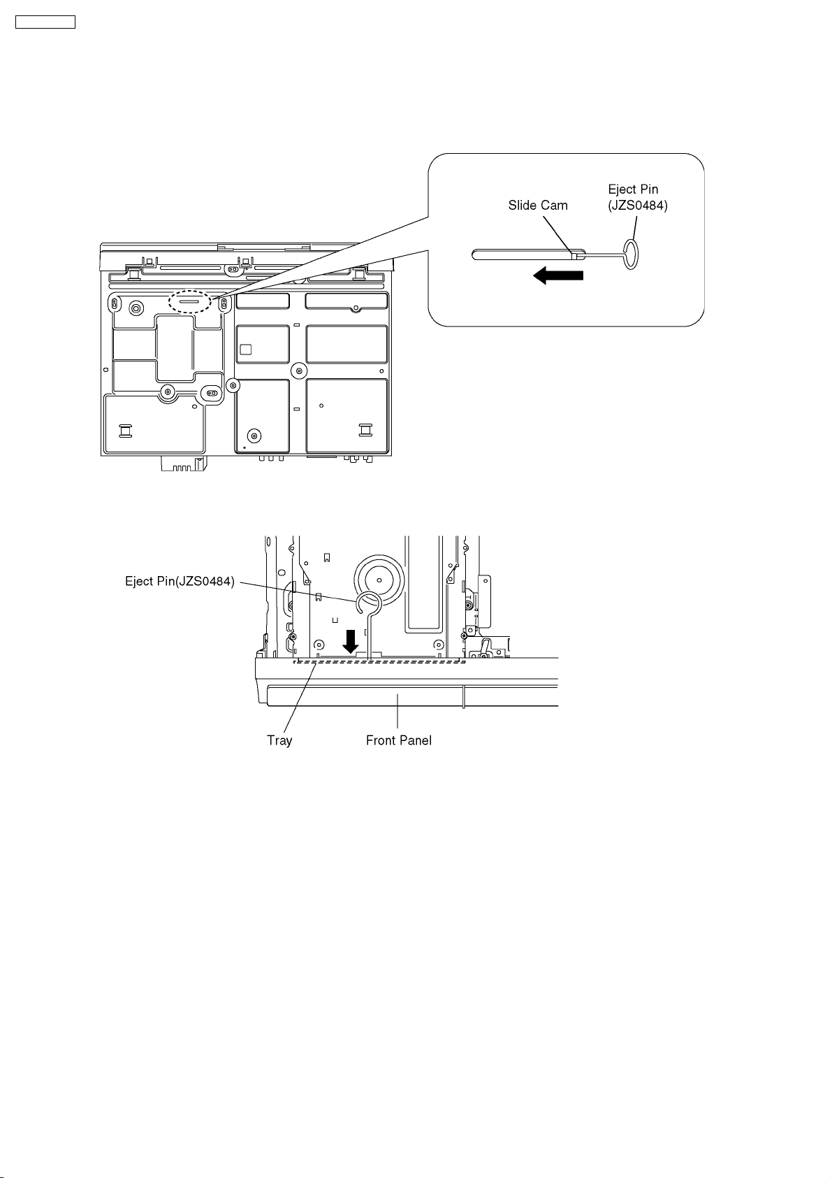
6.1.2. When the Forcible Disc Eject can not be done.
DMR-EH57GN
13
DMR-EH57GN
1. Turn off the power and pull out AC cord.
2. Remove the Top Case.
3. Put deck so that bottom can be seen.
4. Slide SLIDE CAM by Eject Pin (JZJ0484) or minus screw driver (small) in the direction of arrow to eject tray slightly.
5. Put deck upward, and push out Tray by Eject Pin (JZS0484) or minus screw driver (small).
14
DMR-EH57GN
7 Service Mode
7.1. Self-Diagnosis and Special Mode Setting
7.1.1. Self-Diagnosis Functions
Self-Diagnosis Function provides information for errors to service personnel by “Self-Diagnosis Display” when any error has
occurred.
U**, H** and F** are stored in memory and held.
You can check latest error code by transmitting [0] [1] of Remote Controller in Service Mode.
Automatic Display on FL will be cancelled when the power is turned off or AC input is turned off during self-diagnosis display is ON.
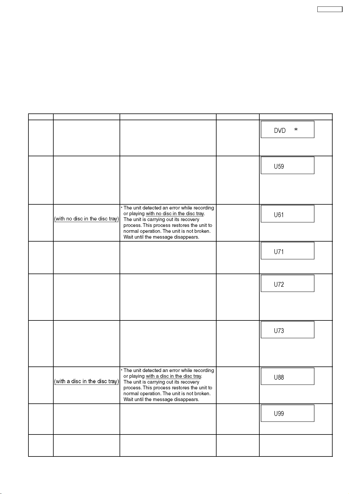
Error Code Diagnosis contents Description Monitor Display Automatic FL display
U30 Remote control code error Display appears when main unit and remote
U59 Abnormal inner temperature
detected
U61 The unit is carrying out its
recovery process.
controller codes are not matched.
Display appears when internal temperature of
deck reaches limit temperature.
The power is turned off forcibly.
For 30 minutes after this, all key entries are
disabled. (Fan motor operates at the highest
speed for the first 5 minutes. For the
remaining 25 minutes, fan motor is also
stopped.) The event is saved in memory as
well.
No display
“*” is remote controller code of the
main unit.
Display for 5 seconds.
No display
“U59 is displayed for 30 minutes.
No display
U71 HDMI incompatible error
(HDCP incompatible)
U72 HDMI connection error
(communication error)
U73 HDMI connection error
(authentication error)
U88 The unit is carrying out its
recovery process.
U99 Hang-up Displayed when communication error has
H19 Inoperative fan motor When inoperative fan motor is detected after
Display this error when the equipment
(compatible with DVI such as TV, amplifier
etc.) connected to the unit by HDMI is
incompatible with HDCP.
*HDCP=High-bandwidth Digital Content
Protection
This error is displayed when there are any
communication problems with the unit and the
equipments (TV, amplifier etc.) connected to
the unit by HDMI. (or when there is a problem
with the HDMI cable)
When authentication error occurs while the
equipments (TV, amplifier etc.) are connected
by HDMI. (or when there is a problem with the
HDMI cable)
occurred between Main microprocessor and
Timer microprocessor.
powered on, the power is turned off
automatically.
The event is saved in memory.
No display
U72 display disappears when
error has been solved by Power
OFF/ON of connecting equipment
or by inserting/removing of HDMI
cable.
No display
U72 display disappears when
error has been solved by Power
OFF/ON of connecting equipment
or by inserting/removing of HDMI
cable.
No display
No display
Displayed is left until the
[POWER] key is pressed.
No display No display
15
DMR-EH57GN
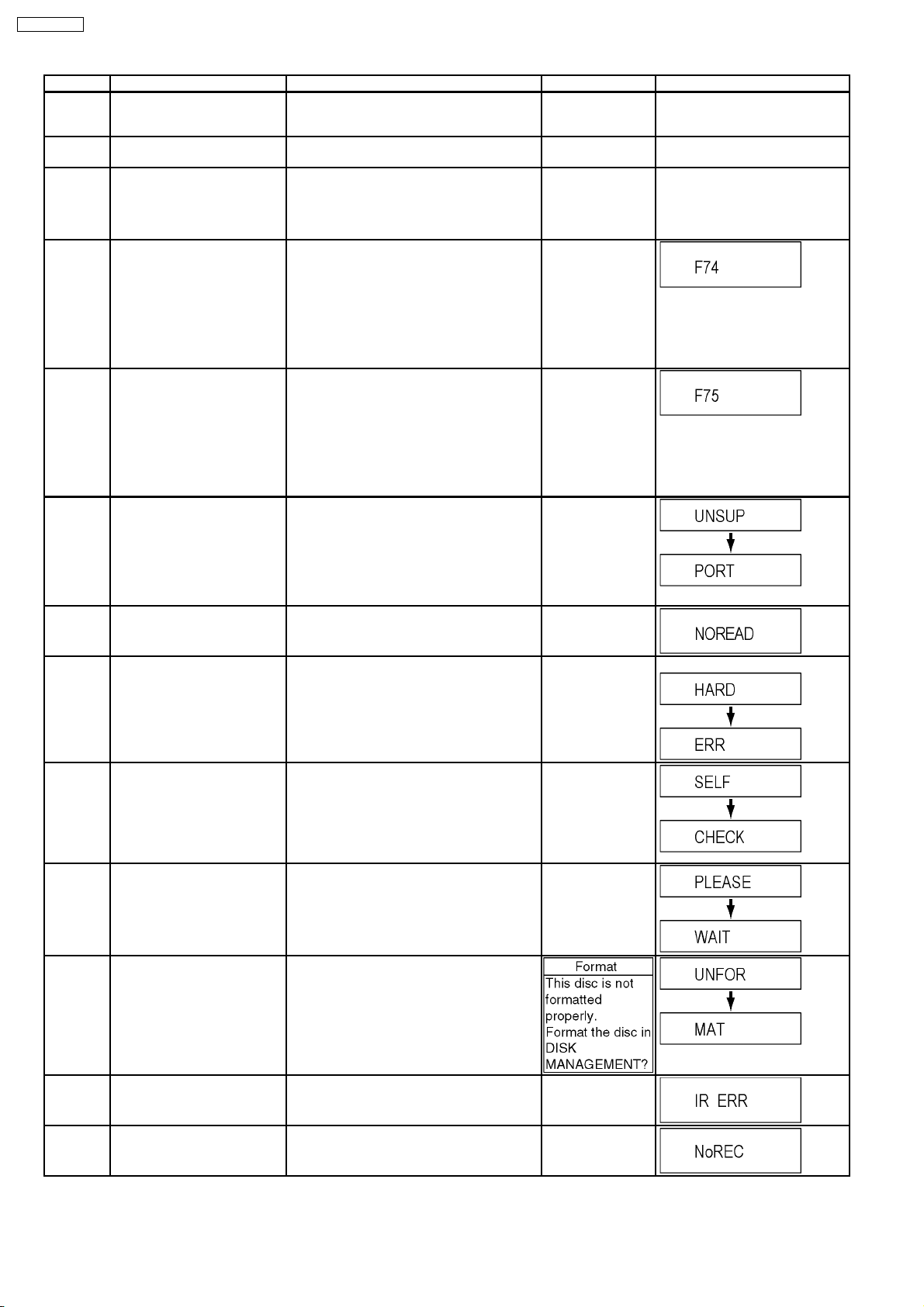
Error Code Diagnosis contents Description Monitor Display Automatic FL display
F00 No error information Initial setting for error code in memory
No display No display
(Error code Initialization is possible with error
code initialization and main unit initialization.)
F58 Drive hardware error When drive unit error is detected, the event is
No display No display
saved in memory.
F34 Initialization error when main
microprocessor is started up
for program recording
When initialization error is detected after
starting up main microprocessor for program
recording, the power is turned off
No display No display
automatically.
The event is saved in memory.
F74 HDIM Device Key
Communication error.
HDMI connection could not be authenticated
due to a transfer malfunction.
No display
Factor of HDMI Device key-road failure
·
· When HDMI LSI is damaged.
· ·
·
· When the bus line of I2C doesn´t operate
· ·
normally.
·
· When device key information recorded is
· ·
damaged.
F75 HDIM Device Key Information
error
HDMI connection could not be authenticated
due to an internal data malfunction.
No display
Factor of HDMI Device key-road failure
·
· When HDMI LSI is damaged.
· ·
·
· When the bus line of I2C doesn´t operate
· ·
normally.
·
· When device key information recorded is
· ·
damaged.
UNSUPPORTUnsupported disc error *An unsupported format disc was played,
although the drive starts normally.
“This disc is
incompatible.”
*The data format is not supported, although
the media type is supported.
*Exceptionally in case of the disc is dirty.
NO READ Disc read error *A disc is flawed or dirty.
*A poor quality failed to start.
*The track information could not be read.
HARD
Drive error The drive detected a hard error. “DVD drive error.” Display for 5 seconds.
ERR
SELF
CHECK
Restoration operation Since the power cord fell out during a power
failure or operation, it is under restoration
operation.
*It will OK, if a display disappears
automatically. If a display does not disappear,
there is the possibility that defective Digital
P.C.B. / RAM drive.
PLEASE
WAIT
Unit is in termination process Unit is in termination process now.
“BYE” is displayed and power will be turned
off.
In case “Quick Start” of setup menu is ON, it
is displayed in restoration operation for AC
off.
UNFORMATUnformatted disc error You have inserted an unformatted DVD-RAM
or DVD-RW that is unformatted or recorded
on other equipment.
Display for 5 seconds.
“Cannot read.
Please check the
disc.”
No display
No display
IR ERR IR communication error [IR ERR] is displayed when communication
between Timer microprocessor and IR
microprocessor fails.
No REC Recording is impossible [No REC] is displayed when recording is
impossible due to the defect, dirt or wound of
media.
16
No display
No display
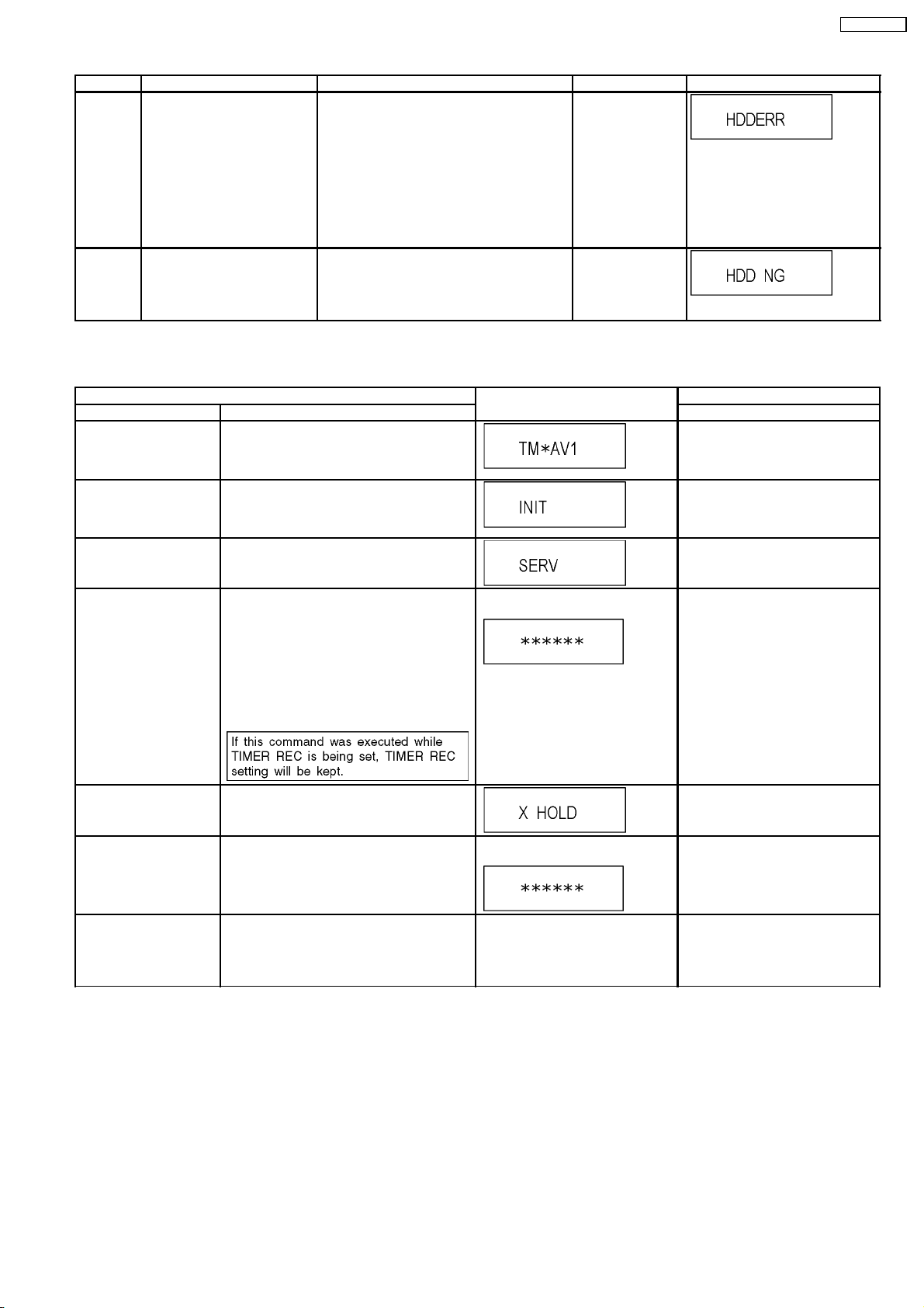
Error Code Diagnosis contents Description Monitor Display Automatic FL display
HDD
ERROR
HDD NG Power on Stand-by setting
[HDD ERR] is displayed when
start up of HDD was failed.
(Except error of setting of
Power on Stand-by)
error
a) When normal start up was failed.
b) When start up at HDD boot was failed.
c) When start up from state of P-OFF was
failed.
d) When start up from state of HDD SLEEP
was failed.
[HDD ERR] is displayed when above each
start up of HDD was failed.
*In case b), tray opens automatically and
[HDDERR] is displayed until version up disc is
inserted.
[HDD NG] is displayed when power on Standby setting of HDD is NG or when HDD which
power on Stand-by is not set to is used.
Please try to replace HDD with junine HDD as
service parts.
No display
No display
7.1.2. Special Modes Setting
Item FL display Key operation
Mode name Description Front Key
TEST Mode *All the main unit´s parameters (include tuner)
are initialized.
Rating password The audiovisual level setting password is
initialized to “Level 8”.
Service Mode Setting every kind of modes for servicing.
*Details are described in “7.1.3. Service
Mode at a glance”.
Forced disc eject Removing a disc that cannot be ejected.
The tray will open and unit will shift to P-off
mode.
*When Timer REC is ON or EXT-LINK is ON,
execute " Forced disc eject " after releasing
Timer REC or EXT-LINK.
*This command is not effective during "Child
lock" is ON.
While Demonstration Lock is being set, this
Forced disc eject function is not accepted.
The display before execution
leaves.
Press [STOP], [CH UP] and
[OPEN/CLOSE] keys
simultaneously for five seconds
when power is off.
Open the tray, set DRIVE SELECT
to DVD, and press [REC] and
[PLAY] simultaneously for 5
seconds.
When the power is off, press [CH
UP], [OPEN/CLOSE] and [REC]
keys simultaneously for 5 seconds.
When the power is off, press
[STOP] and [CH UP] keys
simultaneously for 5 seconds.
DMR-EH57GN
Child lock/unlock Set or release “Child Lock”. Press [ENTER] and [RETURN] by
NTSC/PAL system select To switch PAL/NTSC altemately. The display before execution
Forced power-off When the power button is not effective while
power is ON, turn off the power forcibly.
*When Timer REC is ON or EXT-LINK is ON,
execute “Forced Power-off” after releasing
Timer REC or EXT-LINK.
leaves.
Display in P-off mode. Press [Power] key over than 10
remote controller simultaneously
until [X-HOLD] is displayed.
While the power is on (E-E mode),
press [STOP] and [OPEN/CLOSE]
simultaneously for 5 seconds.
seconds.
17
DMR-EH57GN
Item FL display Key operation
Mode name Description Front Key
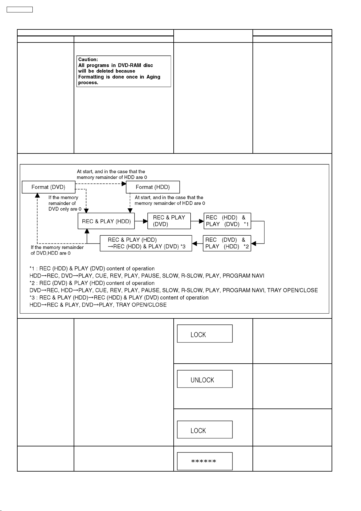
Aging Perform sequence of modes as * Aging
Description shown below continually.
Display following the then mode. When the power is ON, press
[STOP], [POWER] and
[OPEN/CLOSE] simultaneously for
over 5 seconds and less than 10
seconds.
NOTE1:
If Unit has not turned into Aging
mode by operations shown above,
execute TEST MODE once and reexecute operation shown above.
(*All the main unit’s parameters
include tuner are initialized by TEST
mode.)
NOTE2:
If the unit has hung-up because of
pressing keys for over 10 seconds,
once turn off the power, and reexecute this command.
*When releasing Aging mode, press
[POWER] key.
Aging Contents (Example):
Demonstration
lock/unlock
ATP re-execution Re-execute ATP. Display at ATP executing. When the power is on (E-E mode),
Ejection of the disc is prohibited.
The lock setting is effective until unlocking the
tray and not released by “Main unit
initialization” of service mode.
*When lock the tray.
“LOCK” is displayed for 3 seconds.
*When unlock the tray.
“UNLOCK” is displayed for 3
seconds.
*When press OPEN/CLOSE key
while the tray being locked.
Display “LOCK” for 3 seconds.
When the power is on, press
[STOP] and [POWER] keys
simultaneously for 5 seconds in the
condition that a disc in the tray.
NOTE:
Time difference between pressing
[STOP] and [POWER] should be
within 0.5 sec.
When the power is on, press
[STOP] and [POWER] keys
simultaneously for 5 seconds while
the tray being locked.
NOTE:
Time difference between pressing
[STOP] and [POWER] should be
within 0.5 sec.
Press [OPEN/CLOSE] key while the
tray being locked.
press [CH UP] and [CH DOWN]
simultaneously for 5 seconds.
18
DMR-EH57GN
Item FL display Key operation
Mode name Description Front Key
Progressive initialization The progressive setting is initialized to
Interlace.
The display before execution
leaves.
When the power is on (E-E mode),
press [STOP] and [PLAY]
simultaneously for 5 seconds.
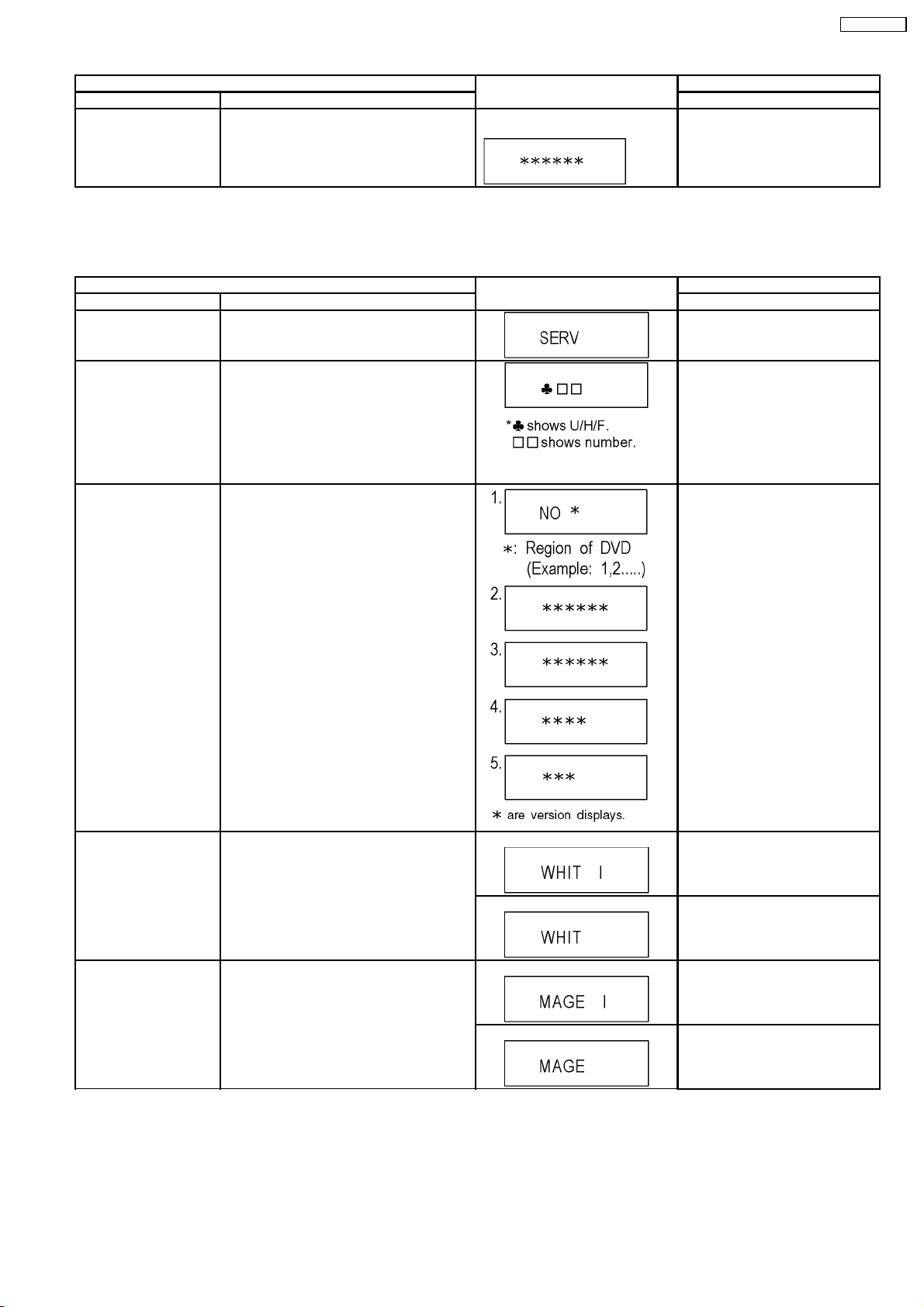
7.1.3. Service Modes at a glance
Service mode setting: While the power is off, press REC, CH UP and OPEN / CLOSE simultaneously for five seconds.
Item FL display Key operation
Mode name Description (Remote controller key)
Release Items Item of Service Mode executing is cancelled. Press [0] [0] or [Return] in service
mode.
Error Code Display Last Error Code of U/H/F held by Timer is
displayed on FL.
*Details are described in “7.1.1. Self-
Diagnosis Functions”.
ROM Version Display 1. Region code (displayed for 5 sec.)
2. Main firm version (displayed for 5 sec.)
3. Timer firm version (displayed for 5 sec.)
4. Drive firm version (displayed for 5 sec.)
5. ROM correction version (displayed for 5
sec.)
Press [0] [1] in service mode
If any error history does not exist,
[F00] is displayed.
Press [0] [2] in service mode
White Picture Output White picture is output as component Output
from AV Decoder.
*White picture
(Saturation rate : 100%)
*It is enable to switch Interlace/Progressive by
“I/P switch: [1] [4]”
Magenta Picture Output Magenta picture is output with Component
Output from AV Decoder.
*Magenta picture
(Saturation rate: 100%)
*It is enable to switch Interlace/Progressive by
“I/P switch: [1] [4]”
*Initial mode is “Interlace”. Press [1] [1] in service mode.
Switch Interlace/Progressive Press [1] [4] in White Picture Output
mode.
*I/P are switched alternately.
*Initial mode is “Interlace”. Press [1] [2] in service mode.
Switch Interlace/Progressive Press [1] [4] in Magenta Picture
Output mode.
*I/P are switched alternately.
19
DMR-EH57GN
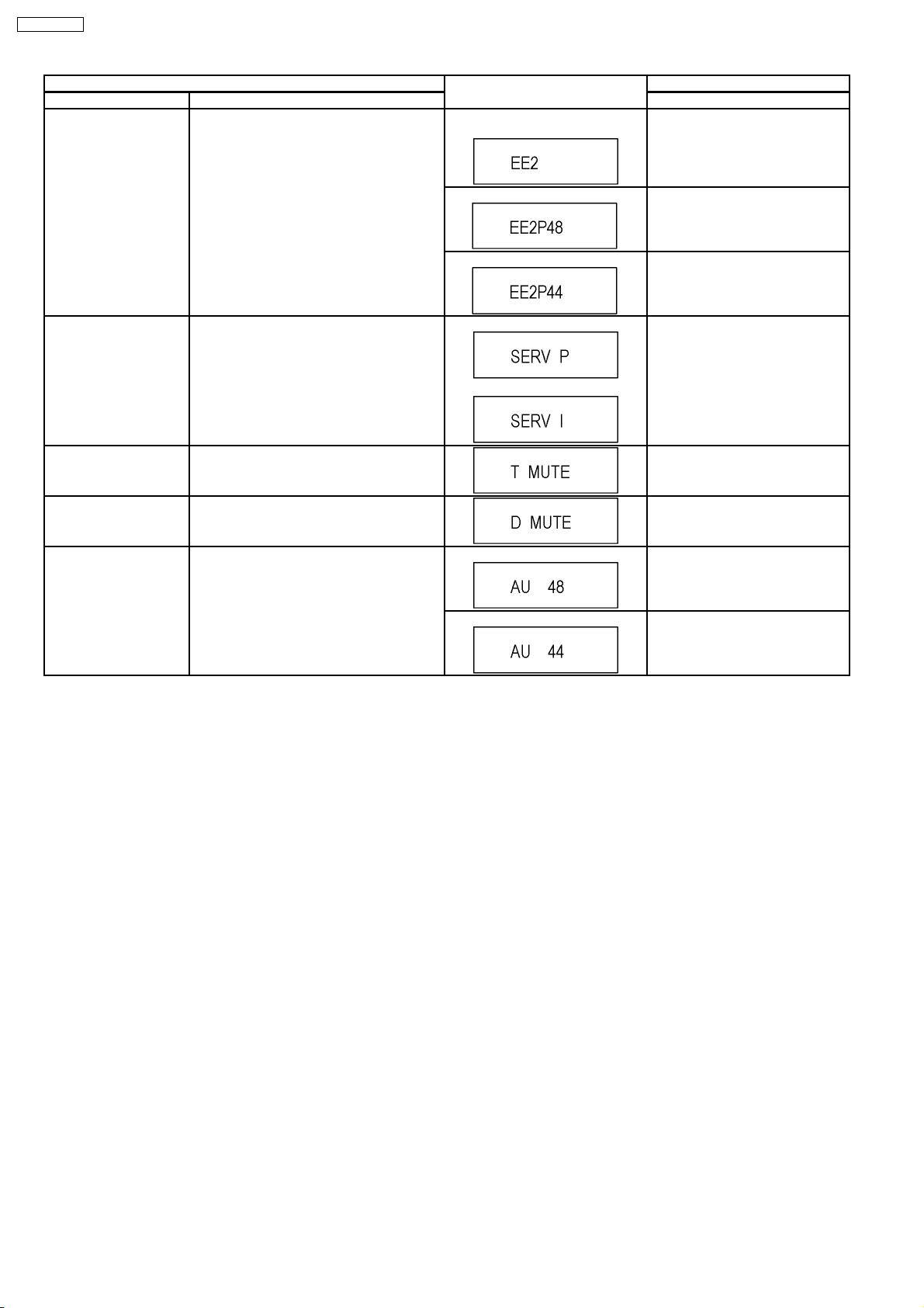
Mode name Description (Remote controller key)
RTSC Return in XP
(A & V)
Item FL display Key operation
AV1 input signal is encoded (XP), decoded
(XP) and output decoded signal to external
Initial mode: EE2/ Interlace/ XP/
Audio 48kHz
Press [1] [3] in service mode.
without DISC recording and DISC playback.
I/P Switch Switch Interlace and Progressive in EE mode.
*Initial setting is “Interlace”.
*This command is effective during executing
“White Picture Output”, “Magenta Picture
Output” and “RTSC Return in XP (A & V)”
modes.
Audio Mute (XTMUTE) Check whether mute is applied normally by
the timer microprocessor.
Audio Mute (XDMUTE) Check whether mute is applied normally by
the Digital P.C.B..
Audio Pattern Output The audio pattern stored in the internal
memory is output
(Lch: 1kHz/-18dB)
(Rch: 400Hz/-18dB)
*Audio sound clock switching operation of
DAC can be confirmed by sub command [2]
[4].
Switch Interlace/Progressive Press [1] [4] in RTSC Return XP
mode.
*I/P are switched alternately.
Audio 44.1 kHz/ 48 kHz Switch Press [2] [4] in RTSC Return XP
mode.
*48 kHz / 44.1 kHz are switched
alternately.
Initial mode is Interlace
Press [1] [4] in I/P Switch mode.
*I/P are switched alternately.
Switch Interlace/Progressive
Press [2] [1] in service mode.
Press [2] [2] in service mode.
Initial mode (Audio 48kHz) Press [2] [3] in service mode.
Audio 44.1kHz/48kHz switching Press [2] [4] in Audio Pattern Output
mode.
*48 kHz / 44.1 kHz are switched
alternately.
20
Item FL display Key operation
Mode name Description (Remote controller key)
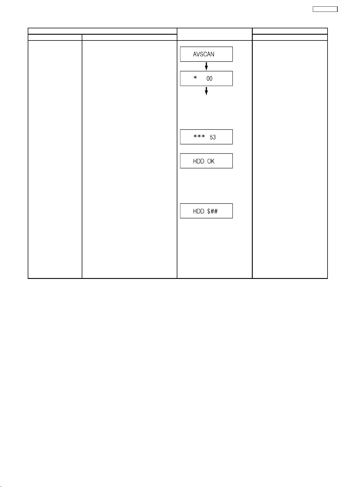
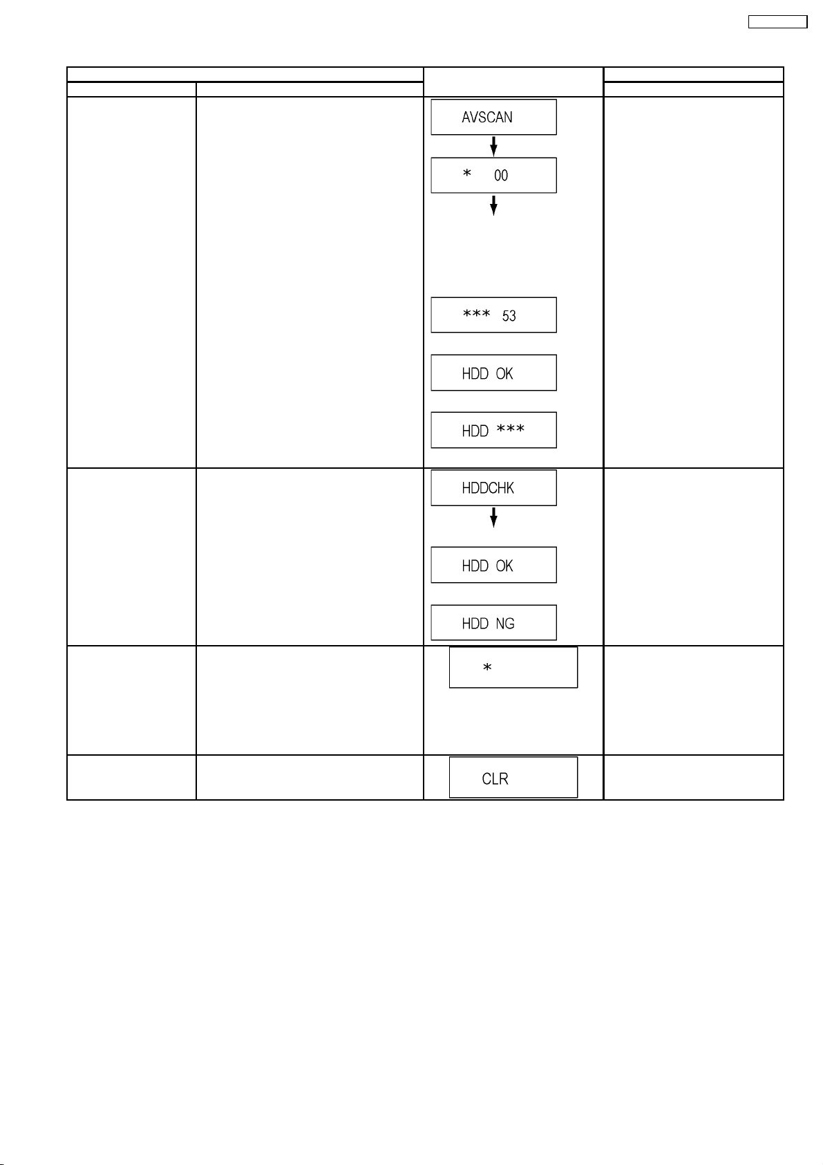
HDD READ SEEK
Inspection
Inspecting seek time of HSS to inspect
performance.
At start
Press [3] [1] in service mode.
* When canceling the inspection
mode while executing, do “forced
power-off”.
Method:
Press [POW ER] key more than 10
seconds.
The [*] sign is added every 20
seconds while inspecting.
Two digits on the right side are the
progress level of the inspection
(The unit is %).
Example on the way of inspection:
When HDD is OK after inspection:
(NG is displayed when error is
excluding o )
(Transfer rate is calculated from the
AV scanning result, and when it is
less than 35Mbps, NG is displayed.
)
DMR-EH57GN
$: [X] is displayed when seek time is
over 270msec., there is error or
transfer rate is NG.
Position at $ is space when
excluding those.
##: Number of data of over
100msec. and less than 270msec.
When it is over 100, [99] is
displayed.
When the number is less than 5, we
judge it normal.
21
DMR-EH57GN
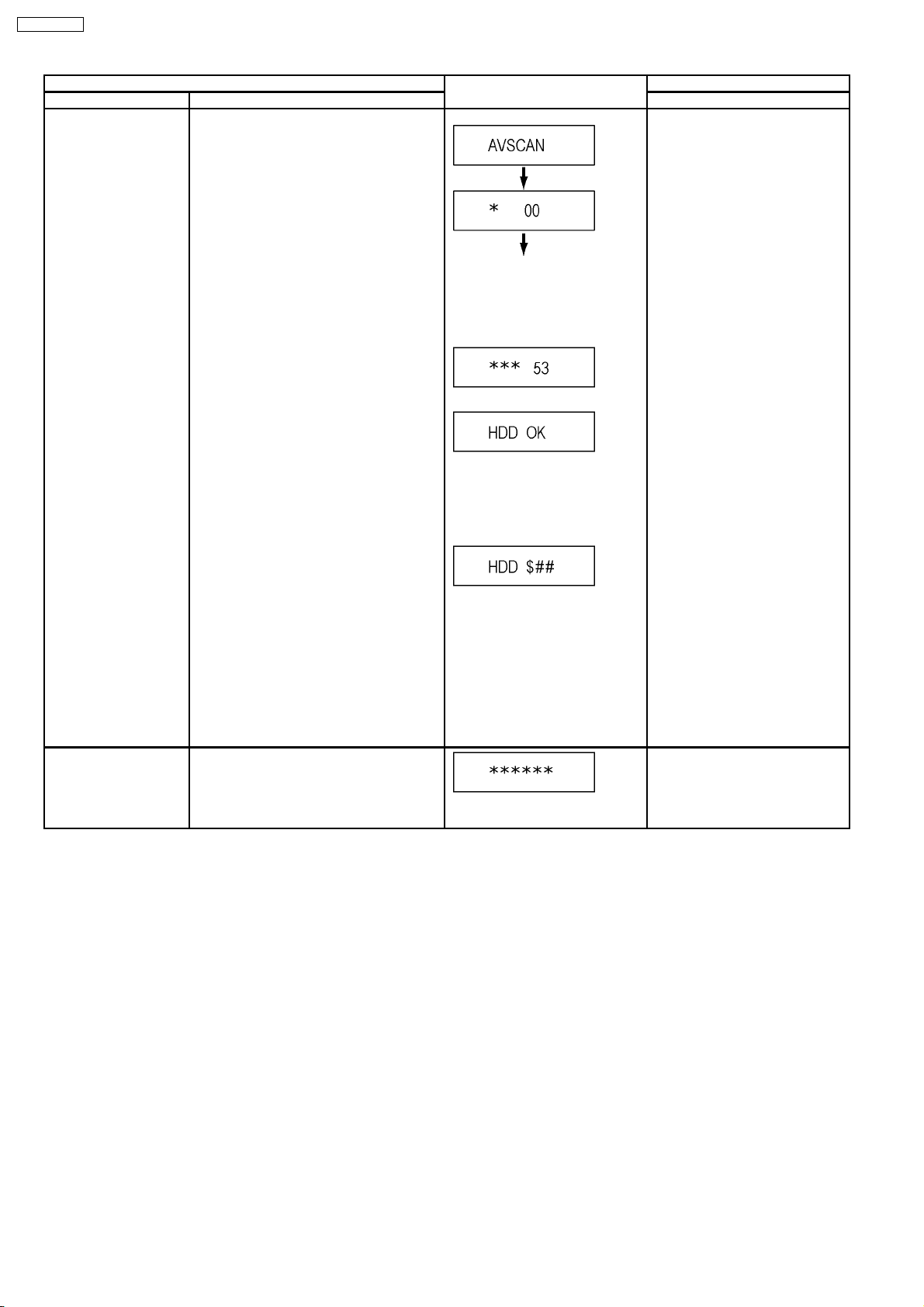
Mode name Description (Remote controller key)
HDD READ VERIFY
Inspection
Item FL display Key operation
Measure of access time in READ VERIFY
MODE of HDD.
At start
Press [3] [2] in service mode.
* When canceling the inspection
mode while executing, do “forced
power-off”.
Method:
Press [POW ER] key more than 10
seconds.
The [*] sign is added every 20
seconds while inspecting.
Two digits on the right side are the
progress level of the inspection
(The unit is %).
Example on the way of inspection:
When HDD is OK after inspection:
(NG is displayed when error is
excluding o )
(Transfer rate is calculated from the
AV scanning result, and when it is
less than 35Mbps, NG is displayed.
)
HDD Spin-up time The accumulation value of the Spin-up time of
HDD is displayed.
$: [X] is displayed when seek time is
over 270msec., there is error or
transfer rate is NG.
Position at $ is space when
excluding those.
##: Number of data of over
100msec. and less than 270msec.
When it is over 100, [99] is
displayed.
When the number is less than 5, we
judge it normal.
Press [3] [3] in service mode.
Spin-up time of HDD is displayed.
(The unit of display is hour.)
22
Item FL display Key operation
Mode name Description (Remote controller key)
HDD High Speed Scan
Press [3] [6] in service mode.
The [*] sign is added every 10
seconds while inspecting.
Two digits on the right side are the
progress level of the inspection
(The unit is %).
Example on the way of inspection:
When HDD is OK after inspection:
When HDD is NG after inspection:
DMR-EH57GN
HDD Check Simple quality judgment of HDD
Laser Used Time
Check laser used time (hours) of drive.
Indiction
Delete the Laser Used
Time
Laser used time stored in the memory of the
unit is deleted.
[*] is the number of data of NG.
Press [3] [7] in service mode.
When HDD is OK:
When HDD is NG:
Press [4] [1] in service mode.
l(*****) is the used time display in
hour.
lLaser used time of DVD/ CD in
Playback/Recording mode is
counted.
Press [9] [5] in service mode.
23
DMR-EH57GN
Item FL display Key operation
Mode name Description (Remote controller key)
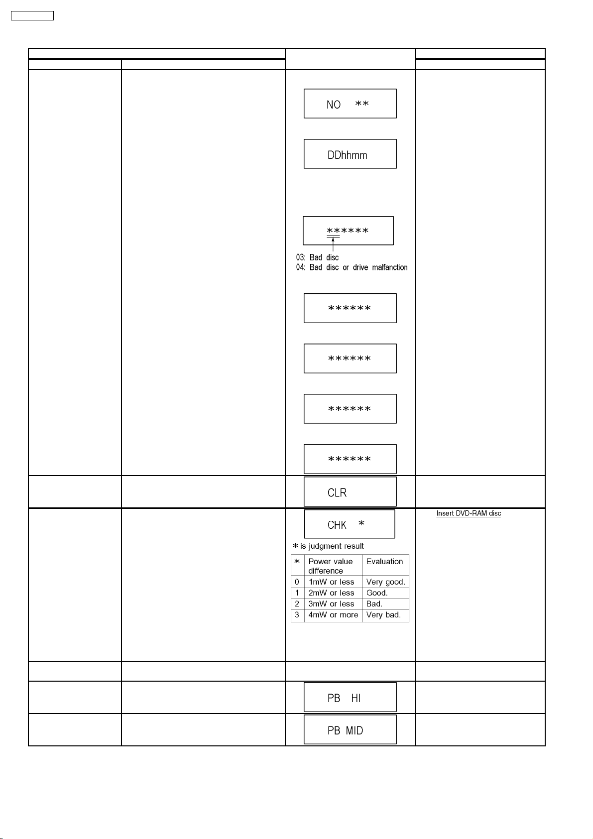
RAM Drive Last Error RAM Drive error code display.
*For details about the drive error code, refer
to the Service Manual for the specific RAM
Drive.
1. Error Number is displayed for 5
seconds.
2. Time when the error has occurred
is displayed for 5 seconds.
DD: Day
hh: Hour
mm: Minute
3. Last Drive Error (1/2) is displayed
for 5 seconds.
4. Last Drive Error (2/2) is displayed
for 5 seconds.
Press [4] [2] in service mode.
When “INFO******” is being
displayed, past 19 error histories
can be displayed by pressing [0] [1]
- [1] [9]
Delete the Last Drive
Error
Delete the Last Drive Error information stored
on the DVD RAM-Drive.
Laser power confirmation Drive state is judged based on difference
between laser power value at shipping and
present laser power value.
5. Error occurring Disc type is
displayed for 5 seconds.
6. Disc Maker ID is displayed for 5
seconds.
7. Factor of Drive Error occurring is
left displayed
In case that the maker cannot be
identified, display is black out.
Press [9] [6] in service mode.
1. into RAM
Drive in service mode. (Other
media are assumed to be noncorrespondence.)
2. Press [4] [4].
Turn on all FL/LEDs All segments of FL and all LEDs are turned
on.
PB HIGH Signal Output 8 pin of AV 1 Jack (PB HIGH terminal) is High
(approx. 11V DC).
PB MIDDLE Signal
Output
8 pin of AV 1 Jack (PB HIGH terminal) is
Middle (approx. 5.5V DC)
If DVD-RAM disc in not inserted,
[NO DISC] is displayed.
If power value study was filed,
[ERROR] is displayed.
All segments are turned on. Press [5] [1] in service mode.
Press [5] [2] in service mode.
Press [5] [3] in service mode.
24
Item FL display Key operation
Mode name Description (Remote controller key)
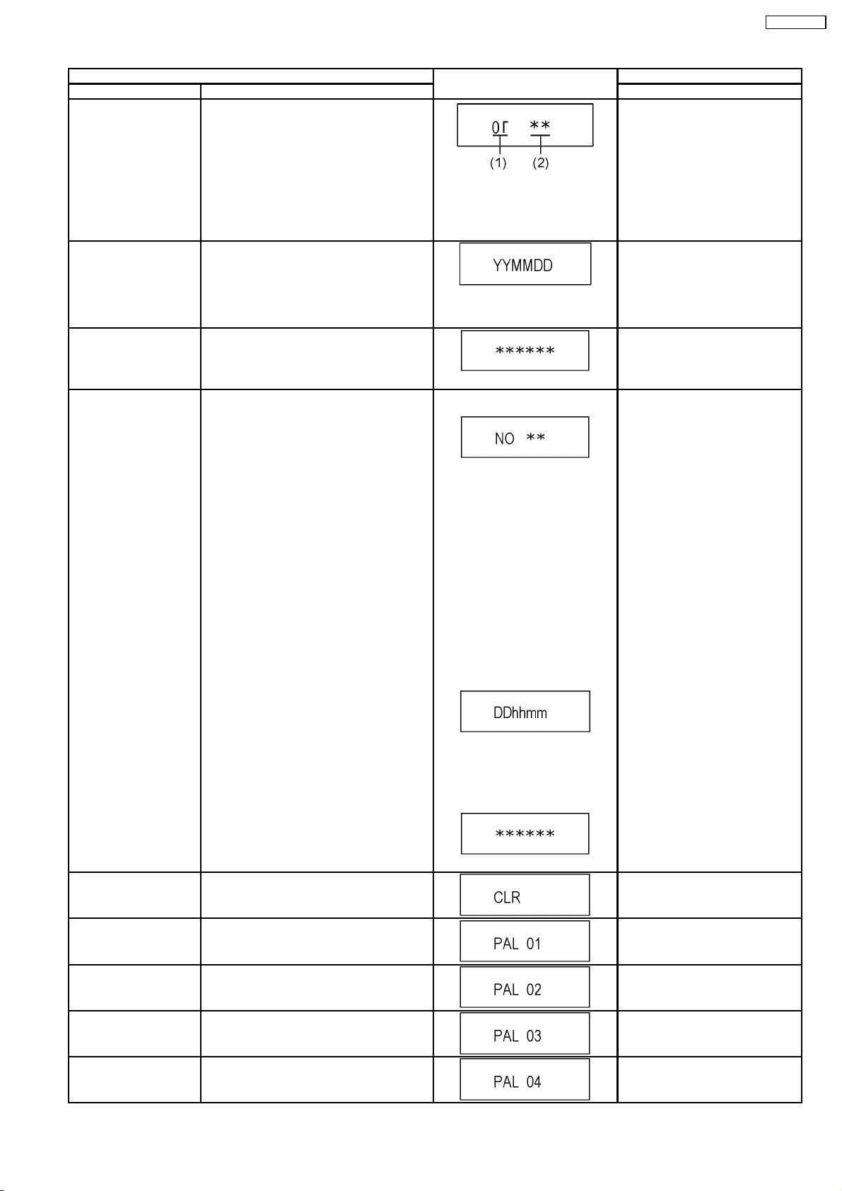
Front connection
inspection
Press all front keys and check the connection
between Main P.C.B. and Front key Switches.
Press [5] [4] in service mode.
(1) Each time a key is pressed,
segment turned on increases one
by one.
(2) Total umber of keys that have
been pressed.
Production Date Display Display the date when the unit was produced.
Press [6] [1] in service mode.
YY: Year
MM: Month
DD: Day
Display the accumulated
Display the accumulated unit´s working time.
Press [6] [4] in service mode.
working time
(Indicating unit: Second)
Display the Error History Display the Error History stored on the unit. Display reason of error for 5
seconds.
Press [6] [5] in service mode.
Then press [0] [1] ~ [9] [9], the past
99 error histories are displayed.
DMR-EH57GN
Delete the Error History Delete Error History information stored on the
unit.
01:
Defect of Digital P.C.B.
(AV DEC / MAIN CPU)
02:
Defect of RAM Drive.
03:
Defect of Disc.
04:
Defect of Digital P.C.B. or
Communication Error.
05:
Defect of Digital P.C.B.
(AV DEC / MAIN CPU)
06:
Defect of HDD.
Display the time when the error has
occurred for 5 seconds.
DD: Day
hh: Hour
mm: Minute
Accumulated working time till
occurring of the error is left
displayed.
(Indicating unit: Second)
Press [9] [7] in service mode.
AV4(V)/AV1(RGB) I/O
Setting
AV2(Y/C)/AV1(V) I/O
Setting
AV2(V)/AV1(Y/C) I/O
Setting
AV2(RGB)/AV1(V) I/O
Setting
Set input to AV4 (V) and set output to AV1
(RGB) for I/O checking
Set input to AV2 (Y/C) and set output to AV1
(V) for I/O checking
Set input to AV2 (V) and set output to AV1
(Y/C) for I/O checking
Set input to AV2 (RGB) and set output to AV1
(V) for I/O checking
Press [8] [0] in service mode.
Press [8] [1] in service mode.
Press [8] [2] in service mode.
Press [8] [3] in service mode.
25
DMR-EH57GN
Item FL display Key operation
Mode name Description (Remote controller key)
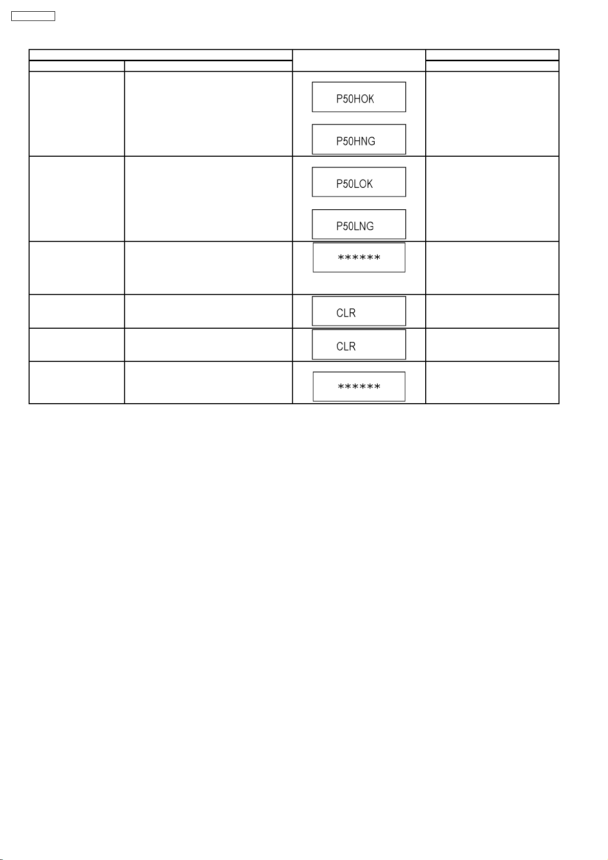
P50(H) Output Timer Microprocessor IC7501-76 output High
signal for AV1-pin 10 passing through inverter
(approx. 0V DC at AV1-pin 10).
When OK.
When NG.
Press [8] [4] in service mode.
P50(L) Output Timer Microprocessor IC7501-76 output Low
When OK.
Press [8] [5] in service mode.
signal for AV1-pin 10 passing through inverter
(approx. 4.4V DC at AV1-pin 10).
When NG.
Tray OPEN/CLOSE Test The tray is opened and closed repeatedly.
Press [9] [1] in service mode
*When releasing this mode, press
the [POWER] button of Remote
“*” is number of open/close cycle
Controller more than 10 seconds.
times.
Error code initialization Initialization of the last error code held by
Press [9] [8] in service mode.
timer (Write in F00)
Initialize Service Last Drive Error, Error history and Error
Press [9] [9] in service mode.
Codes stored on the unit are initialized to
factory setting.
Finishing service mode Release Service Mode. Display in STOP (E-E) mode. Press power button on the front
panel or Remote controller in
service mode.
26

8 Service Fixture & Tools
Part Number Description Compatibility
RFKZ0260 Extension Cable (MainP.C.B. - RAM/Digital P.C.B. Module/ 88 Pin) Same as EH50 Series
RFKZ0327 Extension Cable (MainP.C.B. - Power P.C.B./ 15 Pin) Same as E55 Series
RFKZ0366 Extension FFC (HDD - RAM/Digital P.C.B. Module/ 40 Pin) Same as EH55 Series
RFKZ0168 Extension Cable (Main P.C.B. - Fan Motor/ 3 Pin) Same as E50/ E55 Series
RFKZ0339 Extension Cable (MainP.C.B. - HDD / 4 Pin) Same as EH55 Series
RFKZ0419 Extension Cable (MainP.C.B. - HDMI P.C.B. / 10 Pin) New
JZS0484 Eject Pin Same as E50 Series
RFKZ03D01K Lead Free Solder (0.3mm/100g Reel) Same as EH55 Series
RFKZ06D01K Lead Free Solder (0.6mm/100g Reel) Same as EH55 Series
RFKZ10D01K Lead Free Solder (1.0mm/100g Reel)) Same as EH55 Series
RFKZ0316 Solder Remover (Lead free low temperature Solder/50g) Same as EH55 Series
RFKZ0328 Flux Same as EH55 Series
RFKZ0329 Bottle of Flux Same as EH55 Series
DMR-EH57GN
27
DMR-EH57GN
9 Disassembly and Assembly Instructions
9.1. Disassembly Flow Chart
The following chart is the procedure for disassembling the casing and inside parts for internal inspection when carrying out the
servicing.
To assemble the unit, reverse the steps shown in the chart below.
28
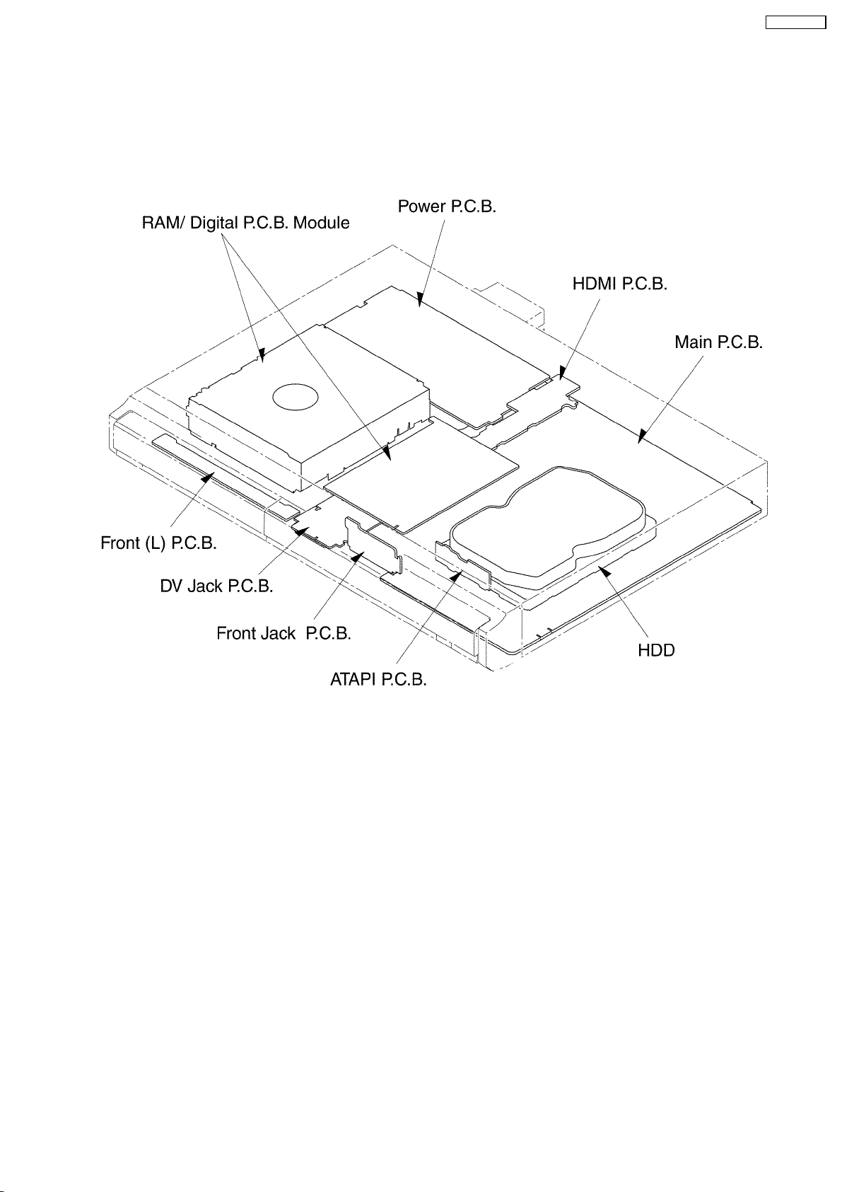
9.2. P.C.B. Positions
DMR-EH57GN
29
DMR-EH57GN
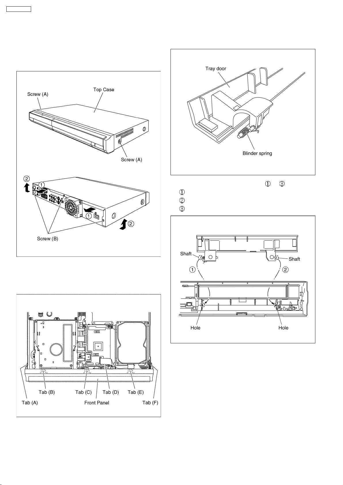
9.3. Top Case
1. Remove the 2 screws (A) and 3 screws (B).
2. Slide Top Case rearward and open the both ends at rear
side of the Top Case a little and lift the Top Case in the
direction of the arrows.
9.4.1. How to assemble Tray door ass’y
1. Attach Blinder spring to Tray door ass’y.
2. Attach Tray door ass’y in order from to .
Put the Brinder spring on the groove.
Insert the shaft in the hole.
Insert the shaft in the hole.
9.4. Front Panel
1. Unlock 6 tabs in (A) - (F) turn.
Pull with the front panel in the direction of your side.
3. Confirm the Brinder spring is attached as following.
30
 Loading...