

Panasonic DMC-GF6X-W Service manual
ORDER NO. DSC1305017CE
B26
Digital Camera/Body/Lens Kit/Double Zoom Lens Kit
Model No. DMC-GF6XEB
DMC-GF6XEC
DMC-GF6XEE
DMC-GF6XEF
DMC-GF6XEG
DMC-GF6XGC
DMC-GF6XGH
DMC-GF6XGK
DMC-GF6XGN
DMC-GF6XGT
DMC-GF6WEB
DMC-GF6WEC
DMC-GF6WEE
DMC-GF6WEF
DMC-GF6WEG
DMC-GF6WGC
DMC-GF6WGH
DMC-GF6WGK
DMC-GF6WGN
DMC-GF6WGT
DMC-GF6KP
DMC-GF6KPC
DMC-GF6KPU
© Panasonic Corporation 2013 Unauthorized copying and distribution is a violation of law.
DMC-GF6KEB
DMC-GF6KGC
DMC-GF6KEC
DMC-GF6KEE
DMC-GF6KEF
DMC-GF6KEG
Colour
[DMC-GF6K]
(K)...........Black Type
(W)..........White Type (except P/PC/PU/GN)
(R)...........Red Type (only EF/GC/GK)
(T)...........Brown Type (only EE/EG/GC/GK)
[DMC-GF6X]
(K)...........Black Type
(W)..........White Type (only EF/GH/GK/GT)
(R)...........Red Type (only EF/GH/GK/GT)
(T)...........Brown Type (only GH/GK/GT)
DMC-GF6K series: Interchangeable Lens (H-FS1442A) is bundled.
DMC-GF6X series: Interchangeable Lens (H-PS14042) is bundled.
DMC-GF6W series: Interchangeable Lens (H-FS1442A/H-FS45150) are bundled.
[DMC-GF6W]
(K)...........Black Type
(W)..........White Type (only GC/GH/GK/GT)
(R)...........Red Type (only GT)
(T)...........Brown Type (only GH/GT)
DMC-GF6KGD
DMC-GF6KGK
DMC-GF6KGN
DMC-GF6KGT
2

TABLE OF CONTENTS
PAG E PAG E
1 Safety Precautions ----------------------------------------------- 4
1.1. General Guidelines---------------------------------------- 4
1.2. Leakage Current Cold Check--------------------------- 4
1.3. Leakage Current Hot Check (See Figure. 1) ------- 4
1.4. How to Discharge the E.Capacitor on Flash
Sub P.C.B. Unit--------------------------------------------- 5
2 Warning-------------------------------------------------------------- 6
2.1. Prevention of Electrostatic Discharge (ESD)
to Electrostatically Sensitive (ES) Devices---------- 6
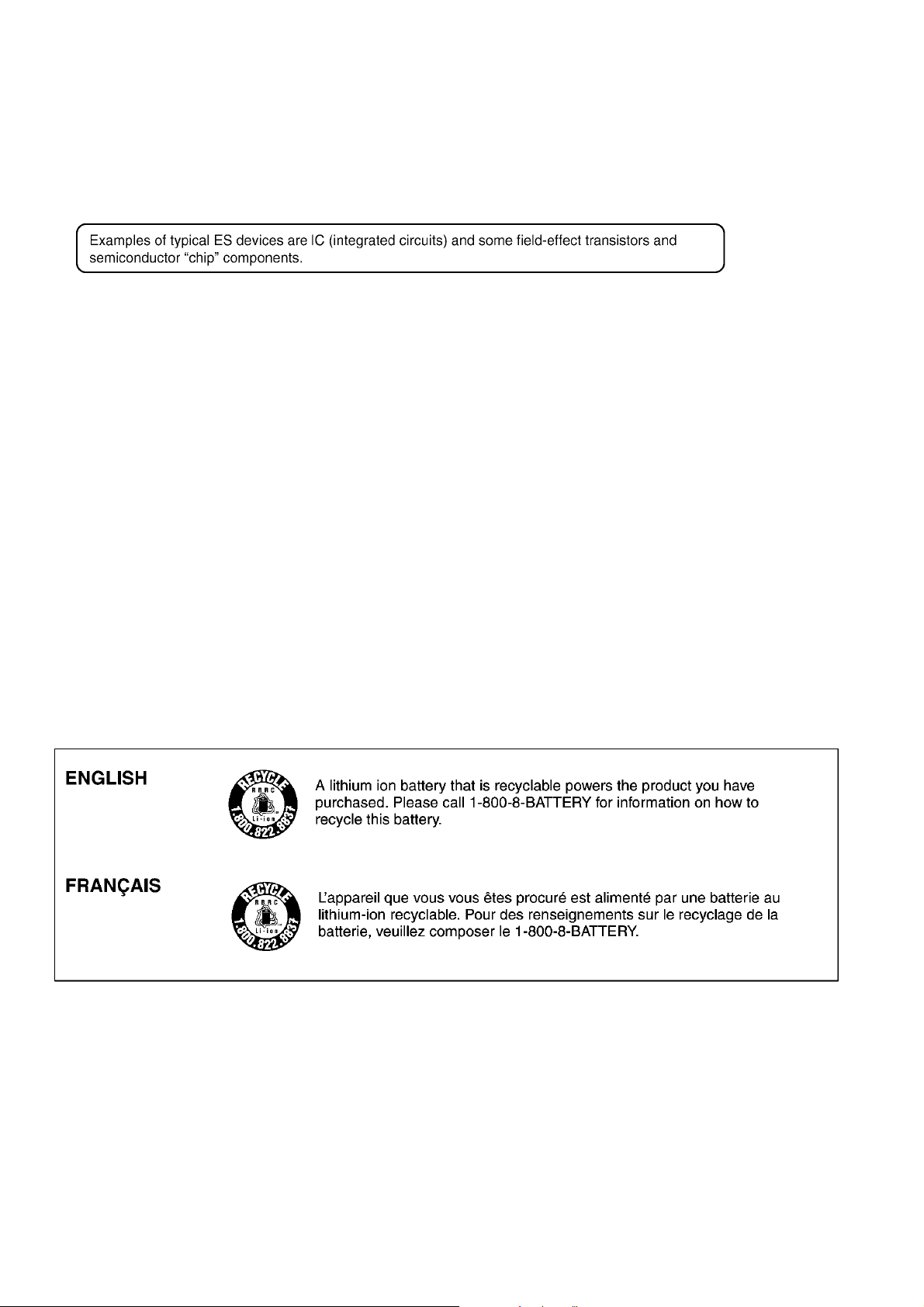
2.2. How to Recycle the Lithium Ion Battery (U.S.
Only) ---------------------------------------------------------- 6
2.3. Caution for AC Cord (For EB/GC/GH) --------------- 7
2.4. How to Replace the Lithium Battery ------------------ 8
3 Service Navigation ----------------------------------------------- 9
3.1. Introduction-------------------------------------------------- 9
3.2. About service of bundled lenses----------------------- 9
3.3. Important Notice ------------------------------------------- 9
3.4. Service Notes----------------------------------------------13
3.5. General Description About Lead Free Solder
(PbF)---------------------------------------------------------15
3.6. How to Define the Model Suffix (NTSC or PAL
model) -------------------------------------------------------16
4 Specifications ----------------------------------------------------20
5 Location of Controls and Components ------------------26
6 Service Mode -----------------------------------------------------28
6.1. Error Code Memory Function--------------------------28
7 Troubleshooting Guide ----------------------------------------30
7.1. Checking Method of Body and
Interchangeable Lens -----------------------------------30
7.2. Failure Diagnosis of NFC -------------------------------35
7.3. Wi-Fi P.C.B. ------------------------------------------------35
7.4. Troubleshooting Guide of the acceleration
sensor -------------------------------------------------------36
8 Service Fixture & Tools----------------------------------------37
8.1. Service Fixture and Tools-------------------------------37
8.2. Clean Box --------------------------------------------------38
8.3. Service Position-------------------------------------------39
9 Disassembly and Assembly Instructions ---------------40
9.1. Camera Body Part----------------------------------------40
9.2. Disassembly and Assemble Procedure for the
Lens----------------------------------------------------------52
10 Measurements and Adjustments---------------------------53
10.1. Matrix Chart for Replaced Part and Necessary
Adjustment -------------------------------------------------53
11 Maintenance-------------------------------------------------------55
11.1. Notice in external cleaning -----------------------------55
12 Block Diagram ----------------------------------------------------56
12.1. Overall Block Diagram ----------------------------------56
12.2. System Control Block Diagram -----------------------57
12.3. Video/Audio Process Block Diagram ----------------58
12.4. Sensor Block Diagram ----------------------------------59
12.5. Lens/Flash Block Diagram -----------------------------60
12.6. Power Block Diagram -----------------------------------61
13 Wiring Connection Diagram ---------------------------------62
13.1. Interconnection Diagram--------------------------------62
3
1 Safety Precautions
1.1. General Guidelines
1. IMPORTANT SAFETY NOTICE
There are special components used in this equipment
which are important for safety. These parts are marked by
in the Schematic Diagrams, Circuit Board Layout,
Exploded Views and Replacement Parts List. It is essential that these critical parts should be replaced with manufacturer’s specified parts to prevent X-RADIATION,
shock, fire, or other hazards. Do not modify the original
design without permission of manufacturer.
2. An Isolation Transformer should always be used during
the servicing of AC Adaptor whose chassis is not isolated
from the AC power line. Use a transformer of adequate
power rating as this protects the technician from accidents resulting in personal injury from electrical shocks. It
will also protect AC Adaptor from being damaged by accidental shorting that may occur during servicing.
3. When servicing, observe the original lead dress. If a short
circuit is found, replace all parts which have been overheated or damaged by the short circuit.
4. After servicing, see to it that all the protective devices
such as insulation barriers, insulation papers shields are
properly installed.
5. After servicing, make the following leakage current
checks to prevent the customer from being exposed to
shock hazards.
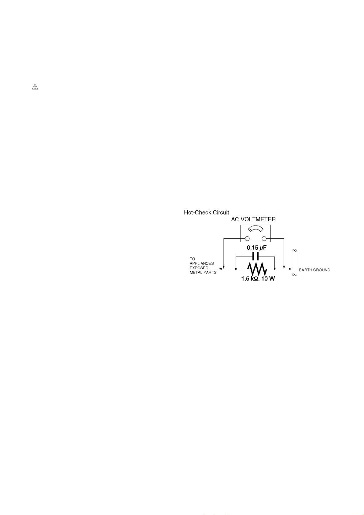
1.3. Leakage Current Hot Check (See Figure. 1)
1. Plug the AC cord directly into the AC outlet. Do not use
an isolation transformer for this check.
2. Connect a 1.5 kΩ, 10 W resistor, in parallel with a 0.15 μF
capacitor, between each exposed metallic part on the set
and a good earth ground, as shown in Figure. 1.
3. Use an AC voltmeter, with 1 kΩ/V or more sensitivity, to
measure the potential across the resistor.
4. Check each exposed metallic part, and measure the voltage at each point.
5. Reverse the AC plug in the AC outlet and repeat each of
the above measurements.
6. The potential at any point should not exceed 0.75 V RMS.
A leakage current tester (Simpson Model 229 or equivalent) may be used to make the hot checks, leakage current must not exceed 1/2 mA. In case a measurement is
outside of the limits specified, there is a possibility of a
shock hazard, and the equipment should be repaired and
rechecked before it is returned to the customer.
1.2. Leakage Current Cold Check
1. Unplug the AC cord and connect a jumper between the
two prongs on the plug.
2. Measure the resistance value, with an ohmmeter,
between the jumpered AC plug and each exposed metallic cabinet part on the equipment such as screwheads,
connectors, control shafts, etc. When the exposed metallic part has a return path to the chassis, the reading
should be between 1 MΩ and 5.2 MΩ. When the exposed
metal does not have a return path to the chassis, the
reading must be infinity.
Figure. 1
4
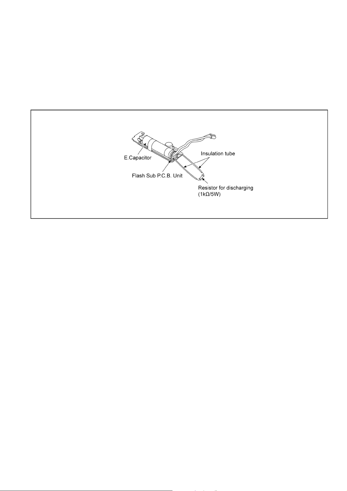
1.4. How to Discharge the E.Capacitor on Flash Sub P.C.B. Unit
CAUTION:
• Be sure to discharge the E.Capacitor on Flash Sub P.C.B. Unit before disassembling.
• Be careful of the high voltage circuit on Flash Sub P.C.B. Unit when servicing.
[Discharging Procedure]
1. Remove the Flash Sub P.C.B. Unit.
2. Put the insulation tube on the lead part of resistor (ERG5SJ102:1kΩ /5W).
(An equivalent type of resistor may be used.)
3. Put the resistor between both terminals of E.Capacitor on Flash Sub P.C.B. Unit for approx. 5 seconds.
4. After discharging, confirm that the E.Capacitor voltage is lower than 10V by using a voltmeter.
Fig. F1
5
2Warning
2.1. Prevention of Electrostatic Discharge (ESD) to Electrostatically Sensitive (ES) Devices
Some semiconductor (solid state) devices can be damaged easily by static electricity. Such components commonly are called Electrostatically Sensitive (ES) Devices.
The following techniques should be used to help reduce the incidence of component damage caused by electrostatic discharge
(ESD).
1. Immediately before handling any semiconductor component or semiconductor-equipped assembly, drain off any ESD on your
body by touching a known earth ground. Alternatively, obtain and wear a commercially available discharging ESD wrist strap,
which should be removed for potential shock reasons prior to applying power to the unit under test.
2. After removing an electrical assembly equipped with ES devices, place the assembly on a conductive surface such as aluminum foil, to prevent electrostatic charge buildup or exposure of the assembly.
3. Use only a grounded-tip soldering iron to solder or unsolder ES devices.
4. Use only an antistatic solder removal device. Some solder removal devices not classified as "antistatic (ESD protected)" can
generate electrical charge sufficient to damage ES devices.
5. Do not use freon-propelled chemicals. These can generate electrical charges sufficient to damage ES devices.
6. Do not remove a replacement ES device from its protective package until immediately before you are ready to install it. (Most
replacement ES devices are packaged with leads electrically shorted together by conductive foam, aluminum foil or comparable conductive material).
7. Immediately before removing the protective material from the leads of a replacement ES device, touch the protective material
to the chassis or circuit assembly into which the device will be installed.
CAUTION :
Be sure no power is applied to the chassis or circuit, and observe all other safety precautions.
8. Minimize bodily motions when handling unpackaged replacement ES devices. (Otherwise harmless motion such as the
brushing together of your clothes fabric or the lifting of your foot from a carpeted floor can generate static electricity (ESD) sufficient to damage an ES device).
2.2. How to Recycle the Lithium Ion Battery (U.S. Only)
6
2.3. Caution for AC Cord (For EB/GC/GH)
2.3.1. Information for Your Safety
IMPORTANT
Your attention is drawn to the fact that recording of prerecorded tapes or discs or other published or broadcast
material may infringe copyright laws.
WARNING
To reduce the risk of fire or shock hazard, do not expose
this equipment to rain or moisture.
CAUTION
To reduce the risk of fire or shock hazard and annoying
interference, use the recommended accessories only.
FOR YOUR SAFETY
DO NOT REMOVE THE OUTER COVER
To prevent electric shock, do not remove the cover. No user
serviceable parts inside. Refer servicing to qualified service
personnel.
2.3.2. Caution for AC Mains Lead
For your safety, please read the following text carefully.
This appliance is supplied with a moulded three-pin mains plug
for your safety and convenience.
A 5-ampere fuse is fitted in this plug.
Should the fuse need to be replaced please ensure that the
replacement fuse has a rating of 5 amperes and it is approved
by ASTA or BSI to BS1362
Check for the ASTA mark or the BSI mark on the body of the
fuse.
2.3.2.1. Important
The wires in this mains lead are coloured in accordance with
the following code:
Blue Neutral
Brown Live
As the colours of the wires in the mains lead of this appliance
may not correspond with the coloured markings identifying the
terminals in your plug, proceed as follows:
The wire which is coloured BLUE must be connected to the terminal in the plug which is marked with the letter N or coloured
BLACK.
The wire which is coloured BROWN must be connected to the
terminal in the plug which is marked with the letter L or coloured
RED.
Under no circumstances should either of these wires be connected to the earth terminal of the three pin plug, marked with
the letter E or the Earth Symbol.
2.3.2.2. Before Use
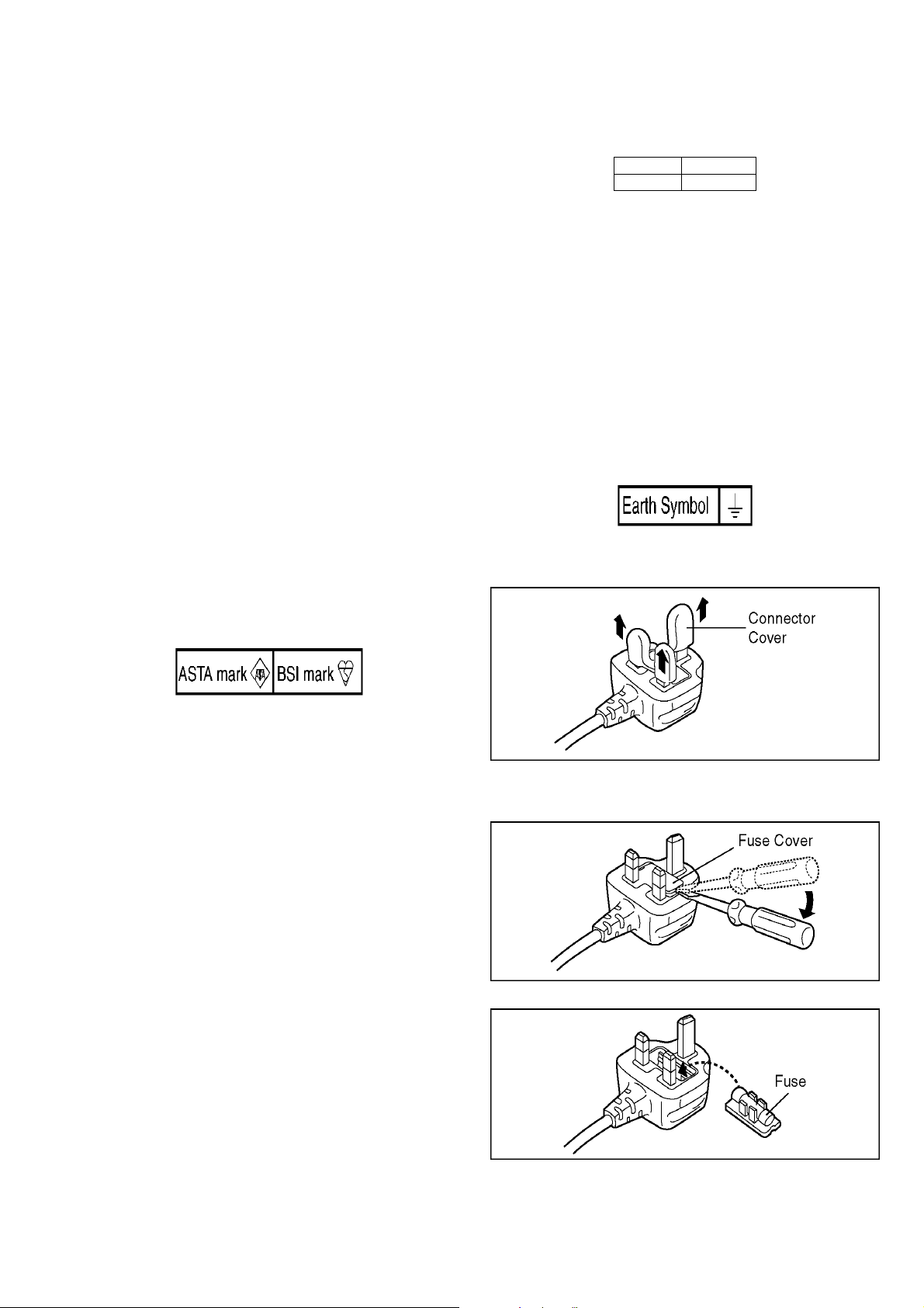
Remove the Connector Cover as follows.
If the plug contains a removable fuse cover you must ensure
that it is refitted when the fuse is replaced.
If you lose the fuse cover, the plug must not be used until a
replacement cover is obtained.
A replacement fuse cover can be purchased from your local
Panasonic Dealer.
If the fitted moulded plug is unsuitable for the socket outlet in
your home then the fuse should be removed and the plug cut
off and disposed of safety.
There is a danger of severe electrical shock if the cut off plug is
inserted into any 13-ampere socket.
If a new plug is to be fitted please observe the wiring code as
shown below.
If in any doubt, please consult a qualified electrician.
2.3.2.3. How to Replace the Fuse
1. Remove the Fuse Cover with a screwdriver.
2. Replace the fuse and attach the Fuse cover.
7
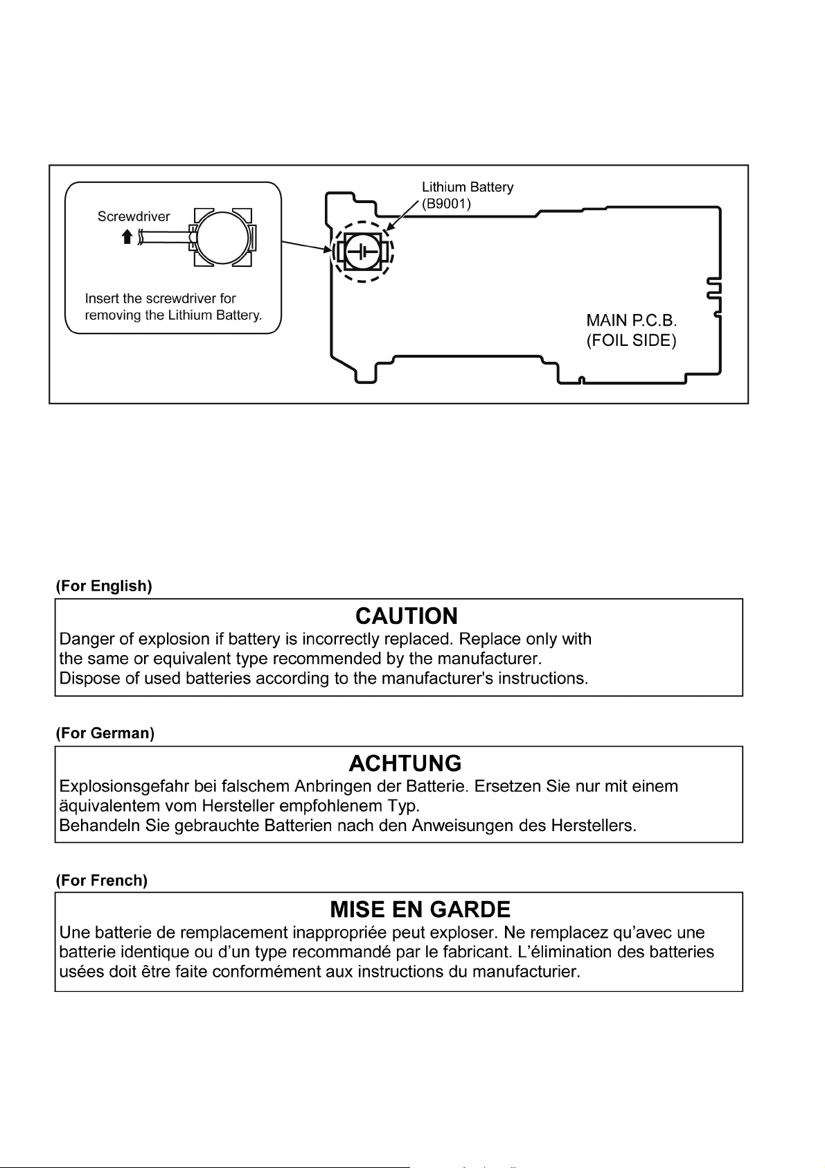
2.4. How to Replace the Lithium Battery
2.4.1. Replacement Procedure
1. Remove the MAIN P.C.B.. (Refer to Disassembly Procedures.)
2. Remove the Lithium battery (Ref. No. “B9001” at foil side of MAIN P.C.B.) and then replace it into new one.
NOTE:
This Lithium battery is a critical component.
(Type No.: ML614 Manufactured by Energy Company, Panasonic Corporation.)
It must never be subjected to excessive heat or discharge.
It must therefore only be fitted in requirement designed specifically for its use.
Replacement batteries must be of same type and manufacture.
They must be fitted in the same manner and location as the original battery, with the correct polarity contacts observed.
Do not attempt to re-charge the old battery or re-use it for any other purpose.
It should be disposed of in waste products destined for burial rather than incineration.
NOTE:
Above caution is applicable for a battery pack which is for DMC-GF6K/GF6X/GF6W series, as well.
8
3 Service Navigation
3.1. Introduction
This service manual contains technical information, which allow service personnel’s to understand and service this model.
Please place orders using the parts list and not the drawing reference numbers.
If the circuit is changed or modified, the information will be followed by service manual to be controlled with original service manual.
3.2. About service of bundled lenses
Please refer to the following service manuals about Disassembly and Assembly or Maintenance of bundled lenses.
• H-FS1442APP/E/GK: Order No.DSC1302014CE
• H-FS45150PP/E/GK: Order No.DSC1209040CE
• H-PS14042PP/E/GK: Order No.DSC1110056CE
3.3. Important Notice
*When servicing, it is recommended dealing with Clean box. (Refer to “8.2. Clean Box” section of this service manual for details.)
3.3.1. Camera Body Unit
3.3.1.1. About Mount Box Unit (Ref. 6)
1. This Service Manual does not contain the following repair service information for “MOUNT BOX UNIT”(Ref.6), because it
requires special facilities and equipment.
a. Schematic diagram, Block diagram and P.C.B. layout.
b. Parts list for individual parts.
2. If the “MOUNT BOX UNIT” is confirmed as defective, exchange the “MOUNT BOX UNIT” as a unit (supplied as service parts
size).
3. Before exchanging the “MOUNT BOX UNIT”, the performances must be carefully checked, by following the “7.Troubleshooting Guide” section of this service manual.
Important:
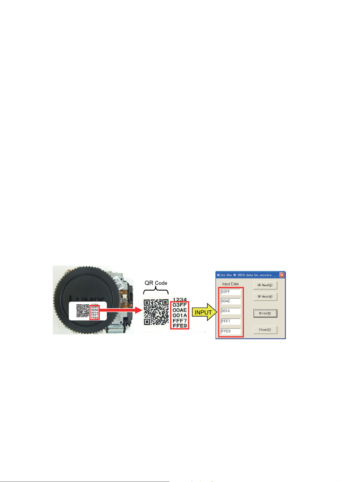
1. After replacing the MOUNT BOX UNIT, the mount box data has to be stored to the unit.
The mount box unit supplied as service parts has affix the label of own configure data.
By inputting these data into the adjustment software and writing these data to Flash-ROM (IC6003), the shutter adjustment
becomes needless.
In addition, the adjustment software can read data encoded to QR code by using WEB camera with a close-up function.
Refer to the adjustment instruction in the adjustment software for details.
Fig. S1
2. The full adjustment must be performed after replacing the “MOUNT BOX UNIT”, otherwise picture quality can not be meet
with specification.
3.3.1.2. About Main P.C.B. (Ref. 1) & Flash-ROM(IC6003)
Important:
1. Before exchanging the “MAIN P.C.B.”, the performances must be carefully checked, by following the “7.Troubleshooting
Guide” section of this service manual.
2. Before replacing the “MAIN P.C.B. and/or Flash-ROM”, proceed the EEPROM data backup from the unit.
After replacing the MAIN P.C.B. and/or Flash-ROM, overwrite the EEPROM data with backup data from the unit first, then proceed the adjustment /inspection.Refer to the adjustment instruction in the adjustment software for details.
3. The full adjustment must be performed after replacing the “MAIN P.C.B. and/or Flash-ROM”, otherwise Picture quality can not
be met with specification.
9
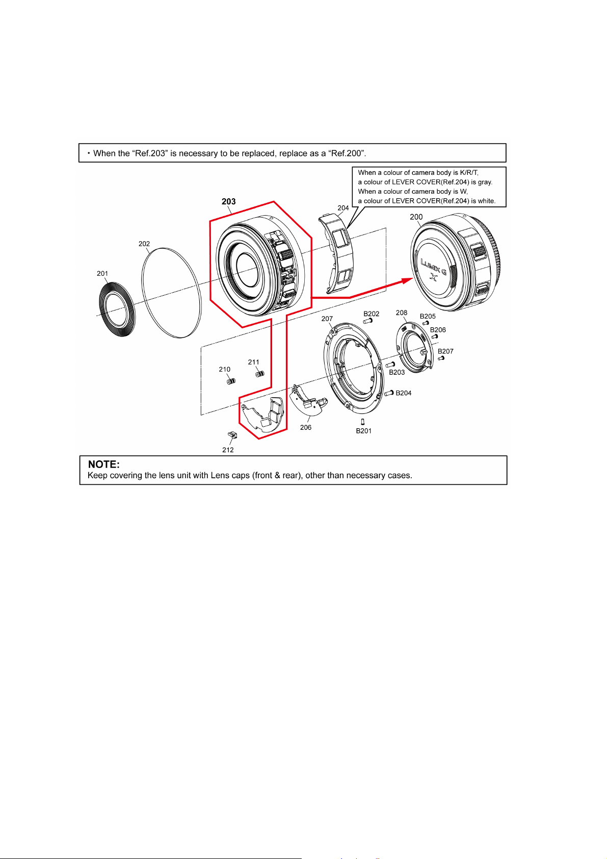
3.3.2. Lens Unit (Interchangeable Lens: H-PS14042)
3.3.2.1. About Lens Main Block Unit (Ref. 203)
1. LENS MAIN BLOCK UNIT (Ref. 203) is not supplied due to difficulty of the transportation issue (Fragile, Dust-free packing),
and requires critical lens adjustments.
Therefore, any needs of the “LENS MAIN BLOCK UNIT” (Ref. 203), carefully confirm its performance in advance.
2. Once “LENS MAIN BLOCK UNIT” (Ref. 203) is confirmed as defective, place order “LENS Unit” (Ref. 200).
Fig. S2
10
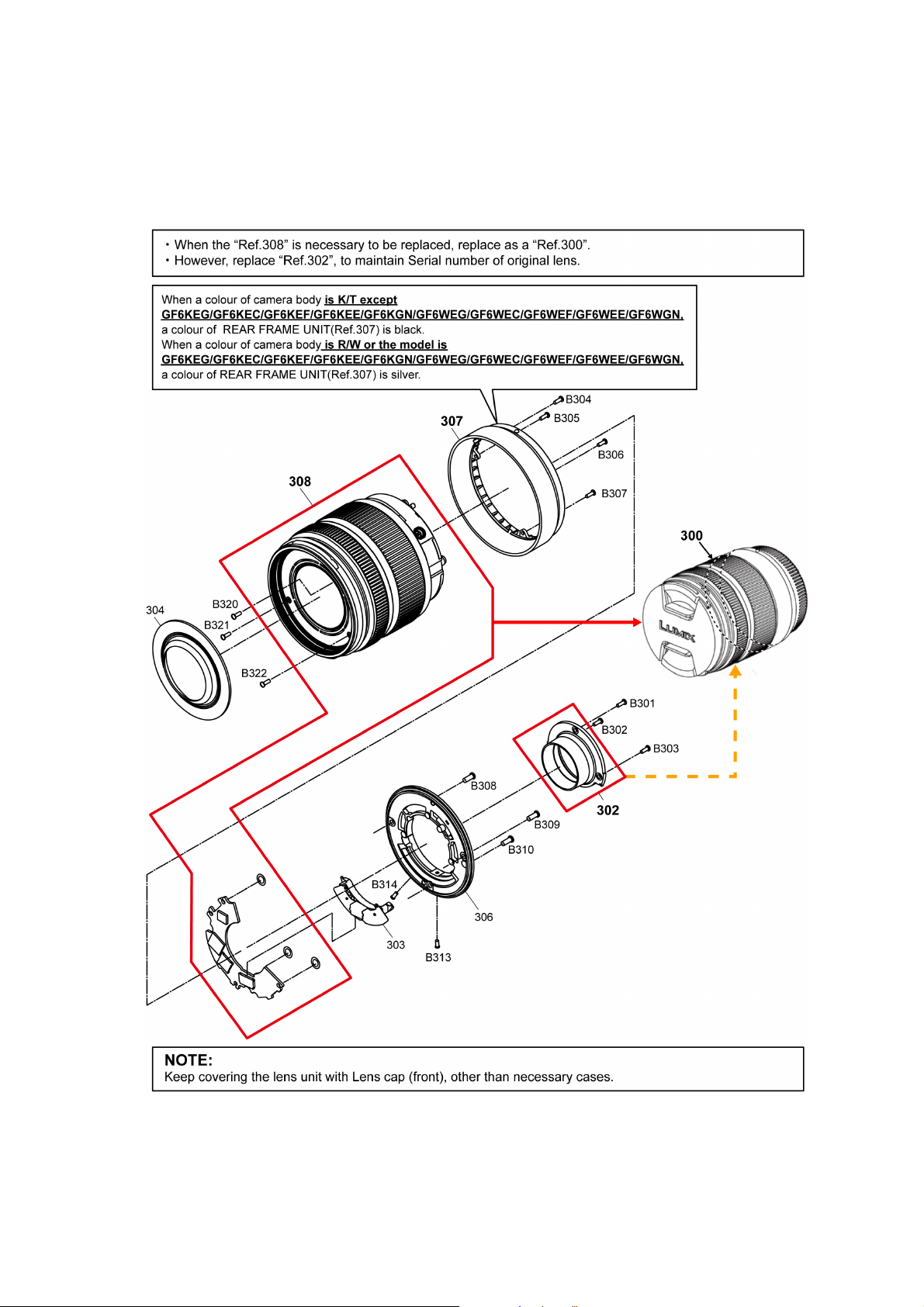
3.3.3. Lens Unit (Interchangeable Lens: H-FS1442A)
3.3.3.1. About Lens Main Block Unit (Ref. 308)
1. LENS MAIN BLOCK UNIT (Ref. 308) is not supplied due to difficulty of the transportation issue (Fragile, Dust-free packing),
and requires critical lens adjustments.
Therefore, any needs of the “LENS MAIN BLOCK UNIT” (Ref. 308), carefully confirm its performance in advance.
2. Once “LENS MAIN BLOCK UNIT” (Ref. 308) is confirmed as defective, place order “LENS Unit” (Ref. 300) and replace
SHADING FRAME (Ref. 302), to maintain Serial number of owner's original lens.
Fig. S3
11
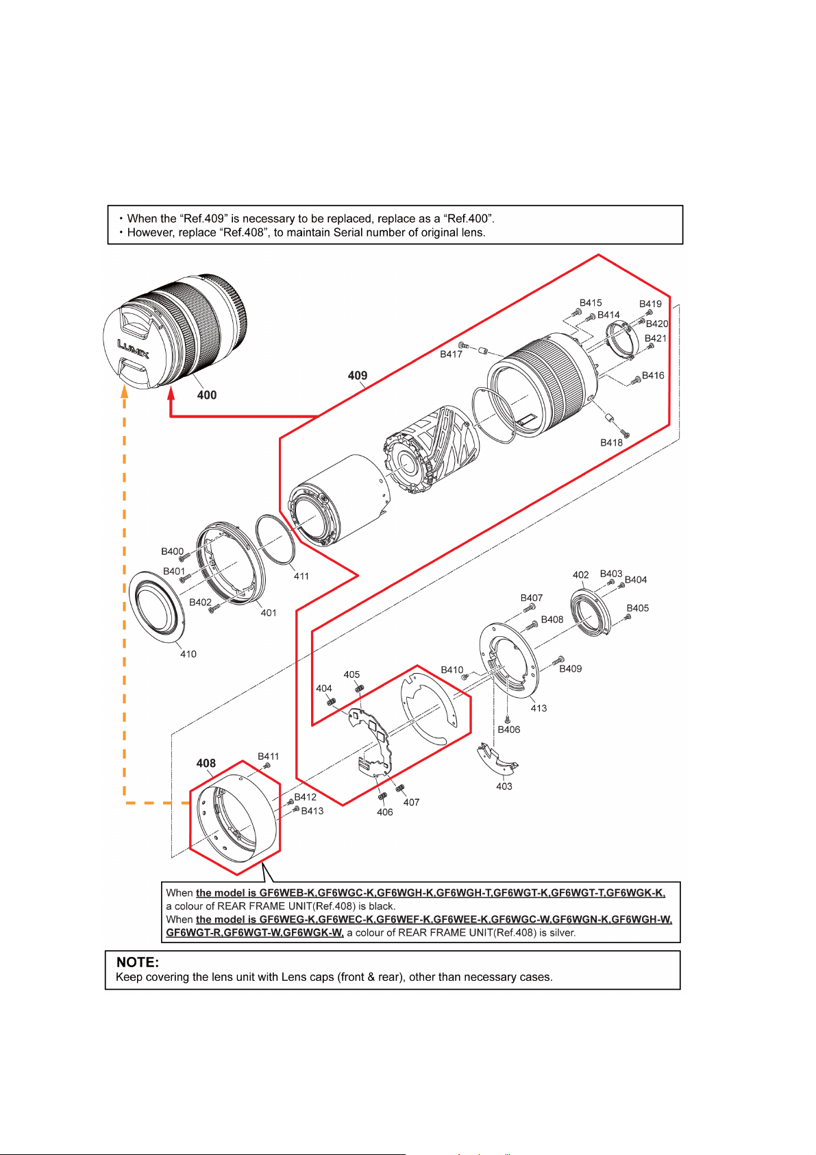
3.3.4. Lens Unit (Interchangeable Lens: H-FS45150)
3.3.4.1. About Lens Main Block Unit (Ref. 409)
1. LENS MAIN BLOCK UNIT (Ref. 409) is not supplied due to difficulty of the transportation issue (Fragile, Dust-free packing),
and requires critical lens adjustments.
Therefore, any needs of the “LENS MAIN BLOCK UNIT” (Ref. 409), carefully confirm its performance in advance.
2. Once “LENS MAIN BLOCK UNIT” (Ref. 409) is confirmed as defective, place order “LENS Unit” (Ref. 400) and replace REAR
FRAME UNIT (Ref. 408), to maintain Serial number of owner’s original lens.
Fig. S4
3.3.5. About Flexible Cable and Connector
Do not touch carelessly so that the foreign body should not adhere to the terminal part of flexible cable and connector.
Wipe off with a clean cloth and the cotton bud, etc. when the terminal part is dirty.
12
3.4. Service Notes
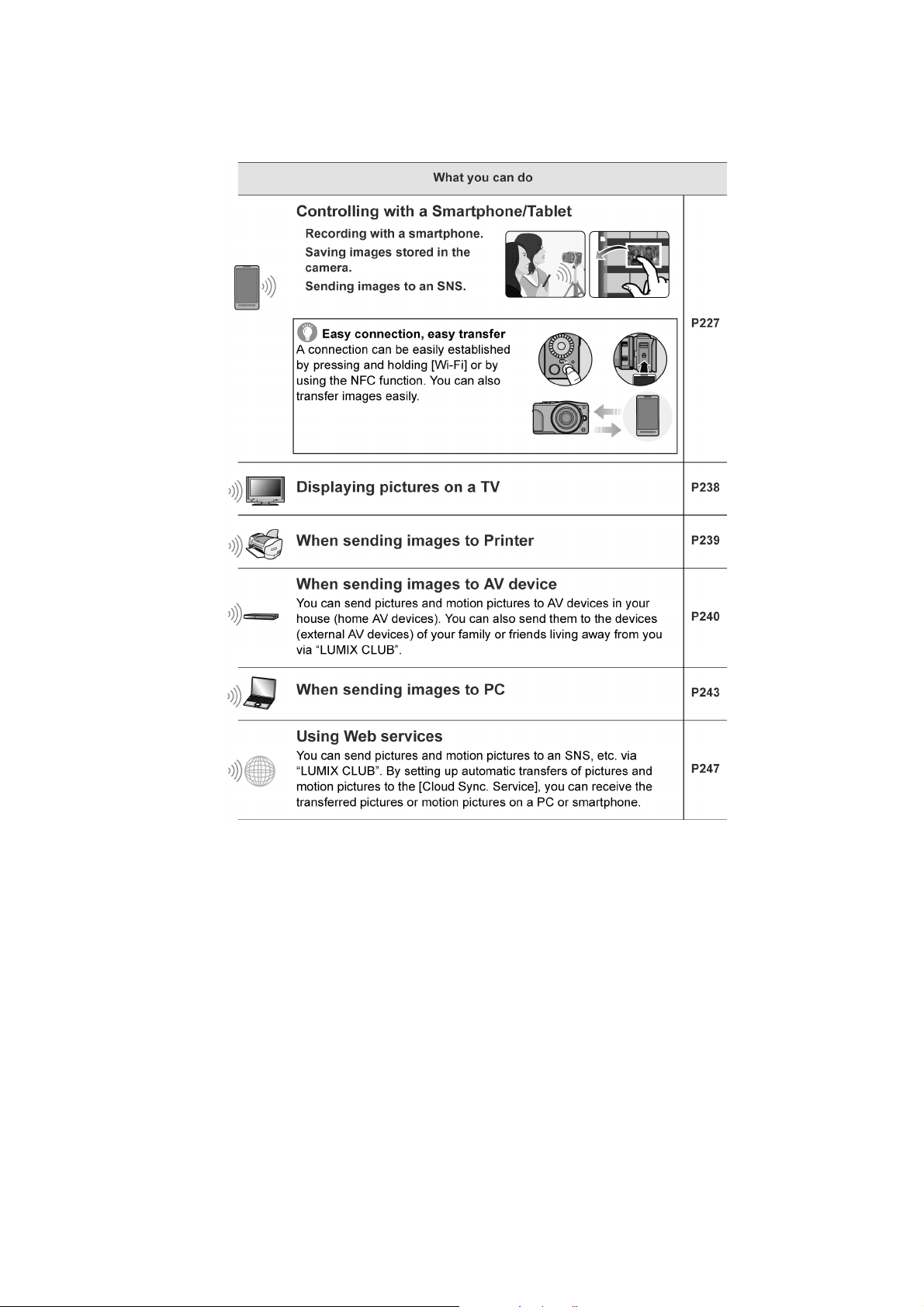
3.4.1. About Wi-Fi Function
The page number in this chapter does not show the page number of this service manual.
13

3.4.2. Important Notice of Servicing
[For The Customer]
Before using your camera please check the Wi-Fi settings.
Depending on what was serviced, the settings may have been reset to the factory defaults.
1. If the settings were reset you will need to reenter your Lumix Club login ID and password.
If you have forgotten the login ID and/or Password, please connect to the Lumix Club web
site and create a new ones.
2.You may also have to reenter the settings for your local Wi-Fi network settings.
We recommend consulting the operating manual if you have any questions.
This Camera unit has the personal information of wireless LAN connection the customer has registered.
For the protection of private information, please erase the personal information after the completion of repair by “INITIAL SETTING”.
In addition, please print out the following documents, and pass to the customer with the Camera unit.
Printing Material [Leaflet for Customer]
14

3.5. General Description About Lead Free Solder (PbF)
The lead free solder has been used in the mounting process of all electrical components on the printed circuit boards used for this
equipment in considering the globally environmental conservation.
The normal solder is the alloy of tin (Sn) and lead (Pb). On the other hand, the lead free solder is the alloy mainly consists of tin
(Sn), silver (Ag) and Copper (Cu), and the melting point of the lead free solder is higher approx.30°C (86°F) more than that of the
normal solder.
Distinction of P.C.B. Lead Free Solder being used
Service caution for repair work using Lead Free Solder (PbF)
• The lead free solder has to be used when repairing the equipment for which the lead free solder is used.
(Definition: The letter of “PbF” is printed on the P.C.B. using the lead free solder.)
• To put lead free solder, it should be well molten and mixed with the original lead free solder.
• Remove the remaining lead free solder on the P.C.B. cleanly for soldering of the new IC.
• Since the melting point of the lead free solder is higher than that of the normal lead solder, it takes the longer time to melt the
lead free solder.
• Use the soldering iron (more than 70W) equipped with the temperature control after setting the temperature at 350±30°C
(662±86°F).
Recommended Lead Free Solder (Service Parts Route.)
• The following 3 types of lead free solder are available through the service parts route.
RFKZ03D01KS-----------(0.3mm 100g Reel)
RFKZ06D01KS-----------(0.6mm 100g Reel)
RFKZ10D01KS-----------(1.0mm 100g Reel)
Note
* Ingredient: tin (Sn) 96.5%, silver (Ag) 3.0%, Copper (Cu) 0.5%, Cobalt (Co) / Germanium (Ge) 0.1 to 0.3%
15
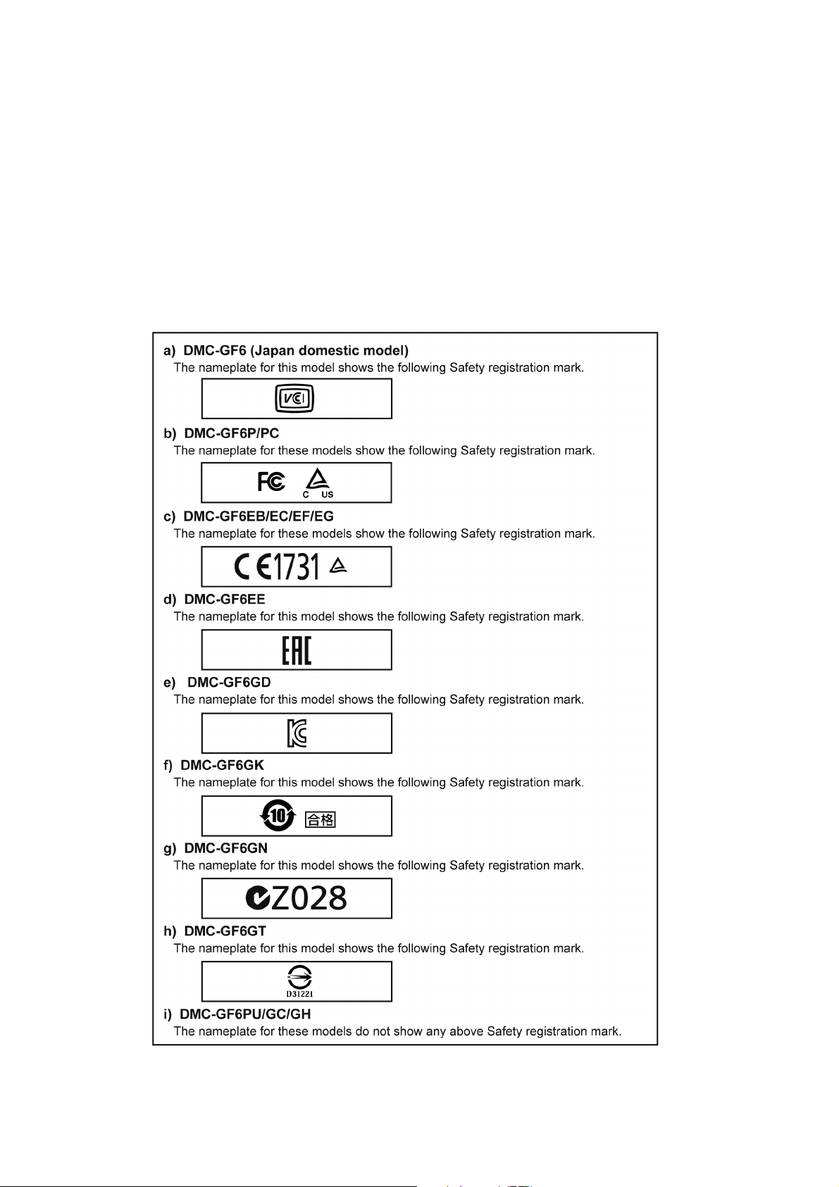
3.6. How to Define the Model Suffix (NTSC or PAL model)
There are nine kinds of DMC-GF6 (Camera body unit), regardless of the colours.
• a) DMC-GF6 (Japan domestic model)
• b) DMC-GF6P/PC
• c) DMC-GF6EB/EC/EF/EG
• d) DMC-GF6EE
• e) DMC-GF6GD
• f) DMC-GF6GK
• g) DMC-GF6GN
• h) DMC-GF6GT
• i) DMC-GF6PU/GC/GH
What is the difference is that the “INITIAL SETTINGS” data which is stored in Flash-ROM mounted on Main P.C.B..
3.6.1. Defining methods:
To define the model suffix to be serviced, refer to the nameplate which is putted on the bottom side of the Unit.
NOTE:
After replacing the Main P.C.B., be sure to achieve adjustment.
Refer to the adjustment instruction in the adjustment software for details.
16
3.6.2. INITIAL SETTINGS:
After replacing the MAIN P.C.B., make sure to perform the initial settings after achieving the adjustment by ordering the following
procedure in accordance with model suffix of the unit.
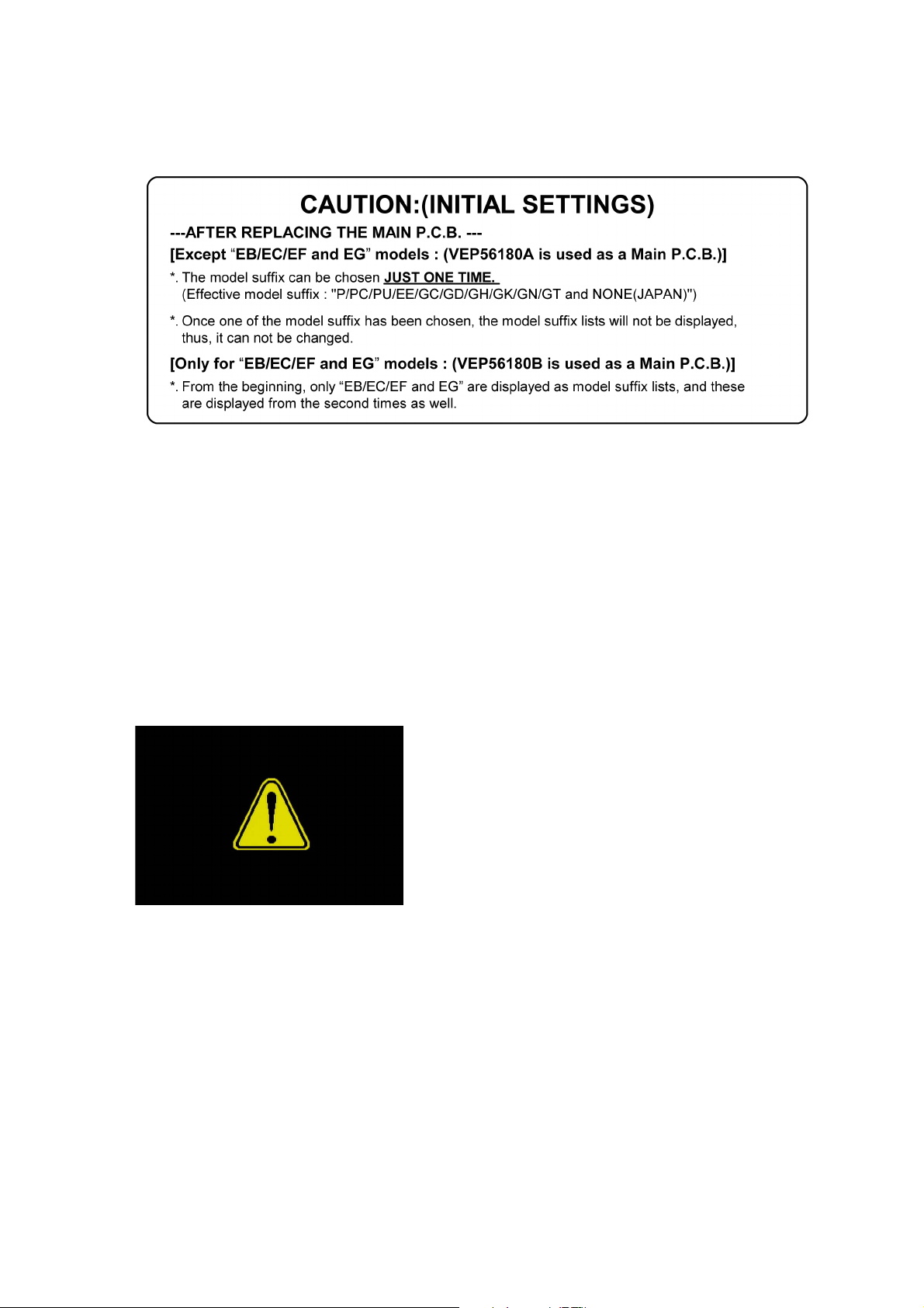
1. IMPORTANT NOTICE:
Before proceeding Initial settings, make sure to read the following CAUTION.
2. PROCEDURES:
• Precautions: Read the above “CAUTION” carefully.
• Preparation:
Attach the fully charged Battery, and insert the memory card.
Confirm that it is not intelligent auto mode [ iA ] or intelligent auto plus mode [ iA+ ].
(If the unit is intelligent auto mode [ iA ] or intelligent auto plus mode [ iA+ ], it does not display the initial setting menu.)
• Step 1. The temporary cancellation of “INITIAL SETTINGS”:
While pressing [ PLAYBACK ] button, [ Q.MENU/Fn1 ] button and “[ RIGHT ] of Cursor buttons” simultaneously, turn the Power
on.
• Step 2. The cancellation of “INITIAL SETTINGS”:
Press the [ PLAYBACK ] button in order to enter the [ PLAYBACK ] mode.
Press [ Q.MENU/Fn1 ] button and “[ UP ] of Cursor buttons” simultaneously, then turn the Power off.
The LCD displays the “ ! ” mark before the unit powers down.
• Step 3. Turn the Power on:
Set the mode dial to [ P ] (Program AE Mode), then turn the Power on.
17
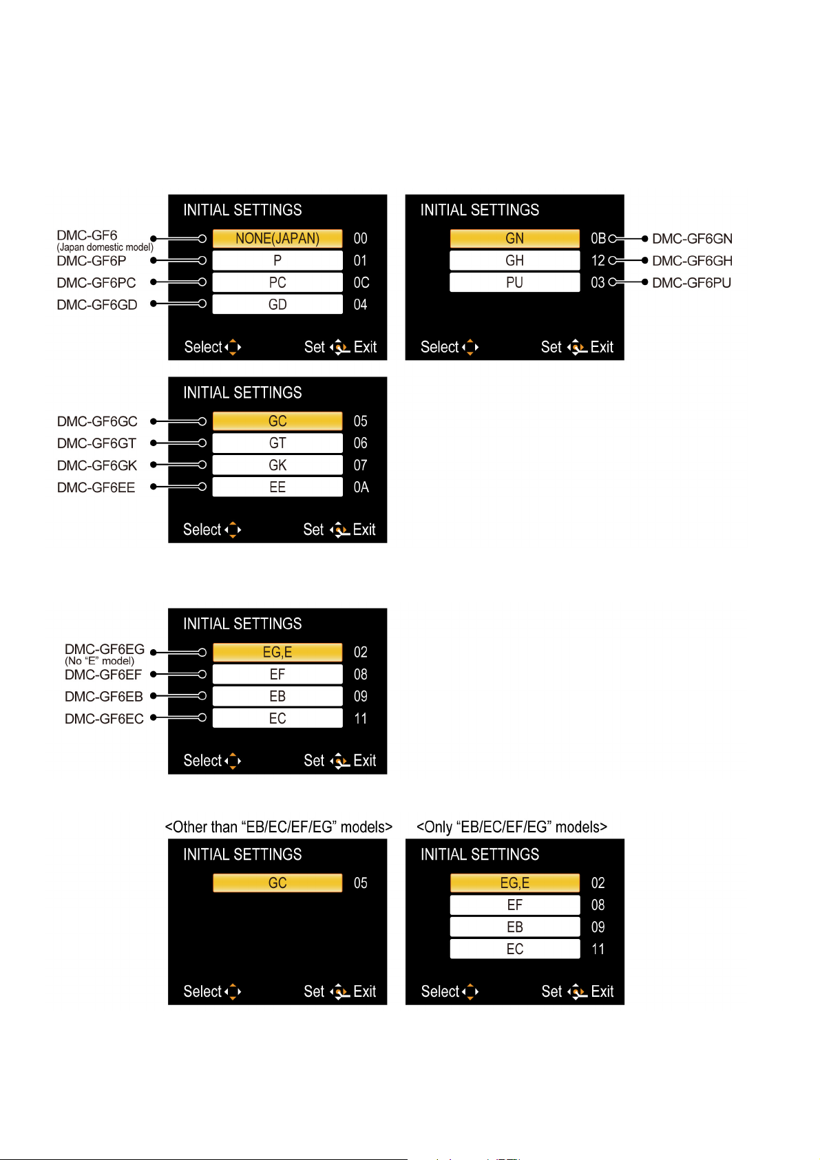
• Step 4. Display the INITIAL SETTING:
While pressing [ MENU/SET ] and “[ RIGHT ] of Cursor buttons” simultaneously, turn the Power off.
The “INTIAL SETTINGS” menu is displayed.
There are two kinds of “INITIAL SETTINGS” menu form as follows:
[ CASE 1. After replacing Main P.C.B. ]
[ Except “EB/EC/EF and EG” models : VEP56180A is used as a Main P.C.B. ]
When Main P.C.B. has just been replaced, 11 model suffixes are displayed as follows. (three pages in total)
[Only “EB/EC/EF and EG” models : (VEP56180B is used as a Main P.C.B.)]
When Main P.C.B. has just been replaced, only 4 model suffixes are displayed as follows.
[CASE 2. Other than “After replacing Main P.C.B.”]
18
• Step 5. Choose the model suffix in “INITIAL SETTINGS”: (Refer to “CAUTION”)
[Caution: After replacing Main P.C.B.]
The model suffix can been chosen, JUST ONE TIME.
Once one of the model suffix have been chosen, the model suffix lists will not be displayed, thus, it can not be changed.
Therefore, select the area carefully.
Select the area with pressing “[ UP ] / [ DOWN ] of Cursor buttons”.
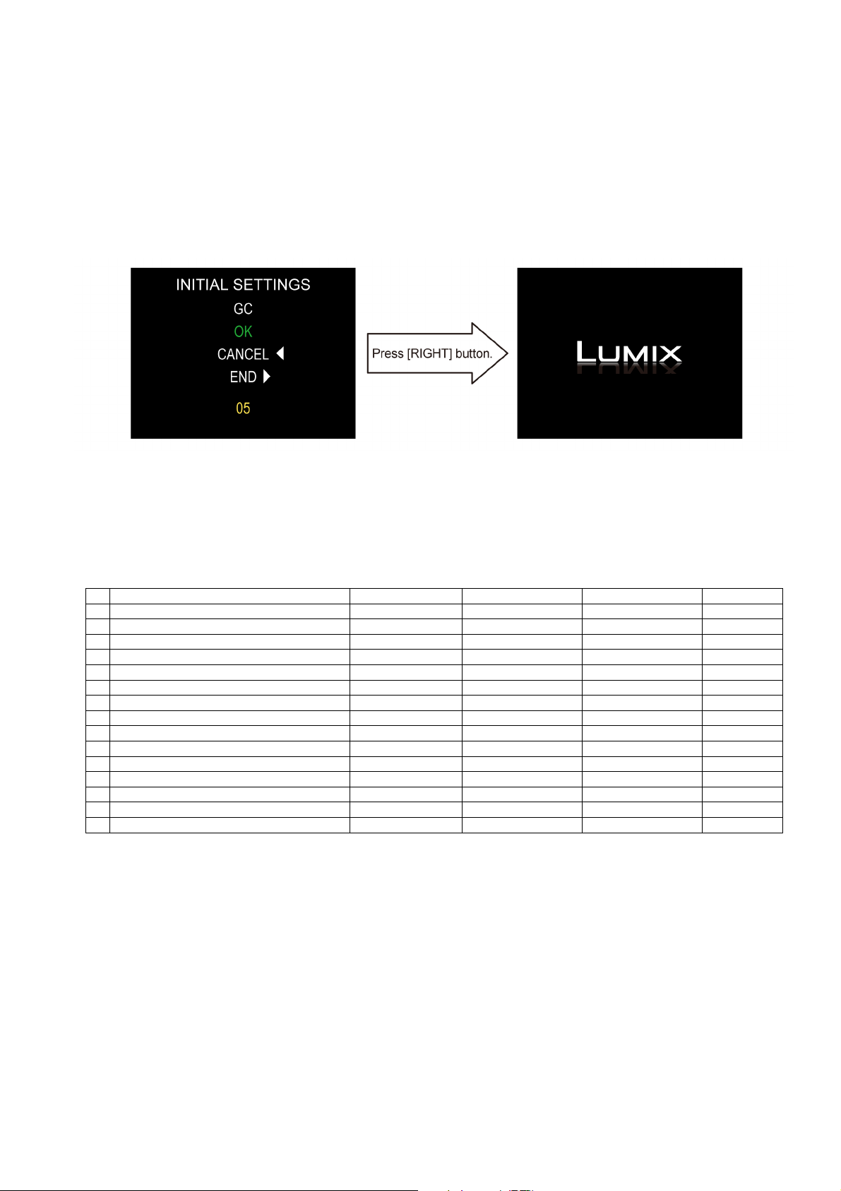
• Step 6. Set the model suffix in “INITIAL SETTINGS”:
Press the “[ RIGHT ] of Cursor buttons”.
The only set area is displayed, and then press the “[ RIGHT ] of Cursor buttons” after confirmation.
(The unit is powered off automatically.)
• Step 7. CONFIRMATION:
Confirm the display of “PLEASE SET THE CLOCK” in concerned language when the unit is turned on again.
When the unit is connected to PC with USB cable, it is detected as removable media.
(When the “GK” or “GT” model suffix is selected, the display shows “PLEASE SET THE CLOCK” in Chinese.)
As for your reference, major default setting condition is as shown in the following table.
• Default setting (After “INITIAL SETTINGS”)
MODEL VIDEO OUTPUT LANGUAGE DATE REMARKS
a) DMC-GF6 (Japan domestic model) NTSC Japanese Year/Month/Date
b) DMC-GF6P NTSC English Month/Date/Year
c) DMC-GF6PC NTSC English Month/Date/Year
d) DMC-GF6PU NTSC Spanish Month/Date/Year
e) DMC-GF6EB PAL English Date/Month/Year
f) DMC-GF6EC PAL English Date/Month/Year
g) DMC-GF6EE PAL Russian Date/Month/Year
h) DMC-GF6EF PAL French Date/Month/Year
i) DMC-GF6EG PAL English Date/Month/Year
j) DMC-GF6GC PAL English Date/Month/Year
k) DMC-GF6GD NTSC Korean Year/Month/Date
l) DMC-GF6GH PAL English Date/Month/Year
m) DMC-GF6GK PAL Chinese (simplified) Year/Month/Date
n) DMC-GF6GN PAL English Date/Month/Year
o) DMC-GF6GT NTSC Chinese (Traditional) Year/Month/Date
19
 Loading...