

Panasonic DMC-FS12PU, DMC-FS12PR, DMC-FS12P, DMC-FS12GT, DMC-FS12GN User Manual
...
ORDER NO. DSC0906054AE
Digital Camera
Model No. DMC-FS12P
DMC-FS12PC
DMC-FS12PR
DMC-FS12PU
DMC-FS12EB
DMC-FS12EE
DMC-FS12EG
B26
DMC-FS12EP
DMC-FS12GC
DMC-FS12GJ
DMC-FS12GK
DMC-FS12GN
DMC-FS12GT
Vol.1
Colour
(S)-------Silver Type (except GT)
(K)-------Black Type (except GT)
(P)-------Pink Type (except EG/GN)
(A)-------Blue Type (only P/PC/PU/EP/GC/GN)
(G)-------Green Type (only P/PC/PU)
Please use this manual together with the service manual for
Model No.DMC-FS7P/PC/PR/PU/EB/EE/EF/EG/EP/GC/GD/GJ/GK/GN/GT Vol.1 Order No.DSC0902005CE
© Panasonic Corporation 2009 Unauthorized copying and distribution is a violation of law.
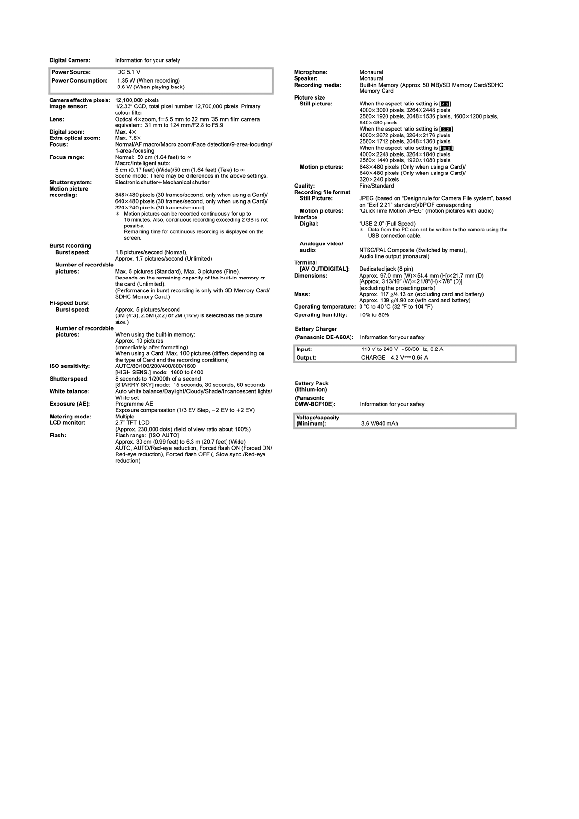
TABLE OF CONTENTS
1 SERVICE NAVIGA TION------------------------------------------3
1.1. INTRODUCTION-------------------------------------------3
1.2. Important Notice 1:(Other than U.S.A. and
Canadian Market)------------------------------------------3
1.3. About the Lens Unit ---------------------------------------3
2 INITIAL SETTINGS------------------------------------------------4
3 Disassembly and Assembly Instructions-----------------7
3.1. Disassembly and Assembly Instructions-------------7
3.2. Assembly Procedure for the Lens ---------------------9
3.3. Removal of the CCD Unit ------------------------------ 11
3.4. Removal of the Focus Motor Unit--------------------12
3.5. The Applyment of Grease Method-------------------12
4DIAGRAMS--------------------------------------------------------13
4.1. Overall Block Diagram----------------------------------13
4.2. Flash Top Schematic Diagram------------------------14
4.3. CCD Flex Schematic Diagram------------------------1 5
4.4. CCD Flex P.C.B.------------------------------------------16
5 REPLACEMENT PARTS LIST -------------------------------17
5.1. Electrical Parts Section---------------------------------17
5.2. Frame and Casing Section ----------------------------18
PAGE PAGE
5.3. Packing Parts and Accessories Section (1)------ 20
5.4. Packing and Accessories Section (2) -------------- 22
2

1 SERVICE NAVIGATION
1.1. INTRODUCTION
This Service Manual contains technical information which will help service personnel to understand and service the Digital Camera
Digital Camera; DMC-FS12 series
The Digital Camera DMC-FS12 series have been developed based on DMC-FS7 series.
Since this Service Manual does not cover the same part which is already described in the Service Manual for DMC-FS7 series,
when servicing, refer to the descriptions in the Service Manual for ;
DMC-FS7P/PC/PR/PU/EB/EE/EF/EG/EP/GC/GD/GJ/GK/GN/GT: Order No.DSC0902005CE (Service Manual Vol. 1).
1.2. Important Notice 1:(Other than U.S.A. and Canadian Market)
When a part replacement is required for repairing MAIN PCB , replace as an assembled parts.
The following category is/are recycle module part. please send it/them to Central Repair Center.
MAIN PCB : VEP56074F
1.3. About the Lens Unit
Although this service manual (for DMC-FS12) is designed based on service manual for DMC-FS7,
the lens unit for DMC-FS12 is only one type.
Therefore, it is able to replace the defective part only.
(Unnecessary to distinguish the lens type. No limitation of the replacement part item described in service manual for FS7.)
Refer to the “Disassembly and Assembly Instructions” and “Exploded views” in details.
3
2 INITIAL SETTINGS
After replacing the MAIN PCB, be sure to perform the initial settings after achieving the adjustment by ordering the following
procedure in accordance with model suffix of the unit.
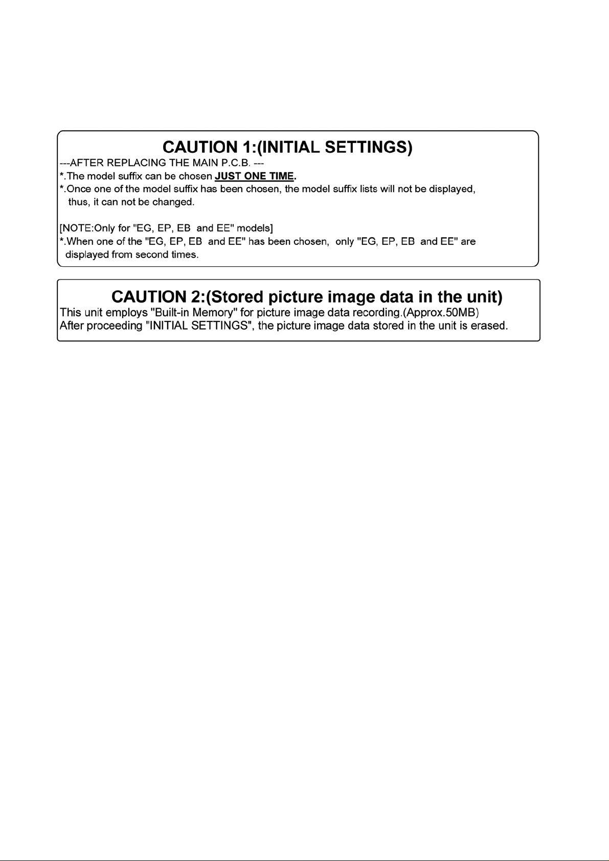
1. IMPORTANT NOTICE:
Before proceeding Initial settings, be sure to read the following CAUTIONS.
2. PROCEDURES:
• Precautions: Read the above “CAUTION 1” and “CAUTION 2”, carefully.
• Preparation:
1. Attach the Battery or AC Adaptor with a DC coupler to the unit.
2. Set the recording mode to the [NORMAL PICTURE] mode.
(Press the [MODE] button and select the [NORMAL PICTURE] by pressing the “[ UP ] and [DOWN] of Cursor buttons”,
then press the [MENU/SET] button.)
NOTE:
If the unit is other than [NORMAL PICTURE] mode, it does not display the initial settings menu.
• Step 1. The temporary cancellation of “INITIAL SETTINGS”:
Set the [REC]/[PLAYBACK] selector switch to “[ REC ] (Camera mark)”.
While keep pressing “[ UP ] of Cursor button” and [ iA ] button simultaneously, turn the Power on.
• Step 2. The cancellation of “INITIAL SETTINGS”:
Set the [REC]/[PLAYBACK] selector switch to “[ PLAYBACK ]”.
Press “[ UP ] of Cursor button” and [ iA ] button simultaneously, then turn the Power off.
• Step 3. Turn the Power on:
Set the [REC]/[PLAYBACK] selector switch to “[ REC ] (Camera mark)”, and then turn the Power on.
• Step 4. Display the INITIAL SETTING:
NOTE:
If the unit is other than [NORMAL PICTURE] mode, it does not display the initial settings menu.
While keep pressing [ MENU/SET ] and “[ RIGHT ] of Cursor buttons” simultaneously, turn the Power off.
The “INITIAL SETTINGS” menu is displayed.
There are two kinds of “INITIAL SETTINGS” menu form as follows:
4
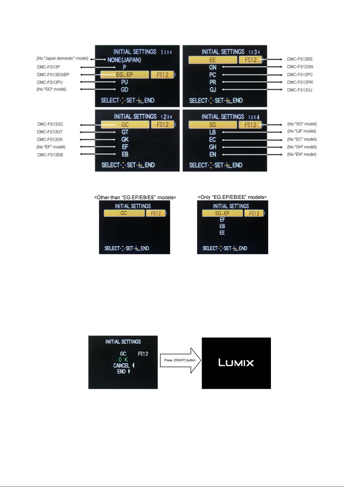
[CASE 1. After replacing MAIN P.C.B.]
When MAIN P.C.B. has just been replaced, all of the model suffix is displayed as follows. (Four pages in total)
[CASE 2. Other than “After replacing MAIN P.C.B.”]
• Step 5. Chose the model suffix in “INITIAL SETTINGS”: (Refer to “CAUTION 1”)
[Caution: After replacing MAIN P.C.B.]
The model suffix can been chosen, JUST ONE TIME.
Once one of the model suffix have been chosen, the model suffix lists will not be displayed, thus, it can be changed.
Therefore, select the area carefully.
Select the area with pressing “[ UP ] / [ DOWN ] of Cursor buttons”.
• Step 6. Set the model suffix in “INITIAL SETTINGS”:
Press the “[ RIGHT ] of Cursor buttons”.
The only set area is displayed, and then press the “[ RIGHT ] of Cursor buttons” after confirmation.
(The unit is powered off automatically.)
5

• Step 7. CONFIRMATION:
Confirm the display of “PLEASE SET THE CLOCK” in concernd language when the unit is turned on again.
When the unit is connected to PC with USB cable, it is detected as removable media.
1) As for your reference, major default setting condition is as shown in the following table.
• Default setting (After “INITIAL SETTINGS”)
MODEL VIDEO OUTPUT LANGUAGE DATE REMARKS
a) DMC-FS12P NTSC English Month/Date/Year
b) DMC-FS12EG PAL English Date/Month/Year
c) DMC-FS12EP PAL English Date/Month/Year
d) DMC-FS12PU NTSC English Month/Date/Year
e) DMC-FS12GC PAL English Date/Month/Year
f) DMC-FS12GT NTSC Chinese (traditional) Year/Month/Date
g) DMC-FS12GK PAL Chinese (Simplified) Year/Month/Date
h) DMC-FS12EB PAL English Date/Month/Year
i) DMC-FS12EE PAL Russian Date/Month/Year
j) DMC-FS12GN PAL English Date/Month/Year
k) DMC-FS12PC NTSC English Month/Date/Year
l) DMC-FS12PR PAL English Date/Month/Year
m) DMC-FS12GJ PAL Thai Date/Month/Year
6
3 Disassembly and Assembly Instructions
3.1. Disassembly and Assembly
Instructions
NOTE: When Disassembling and Assembling for the Lens
1. To minimize the possibility of the CCD being dirt, perform
disassemble and/or assemble under the condition of the
CCD is being mounted.
Disassembling procedures for the CCD unit, refer to item
3.3.
2. Take care that the dust and dirt are not entered into the
lens.
In case of the dust is putted on the lens, blow off them by
airbrush.
3. Do not touch the surface of lens.
4. Use lens cleaning KIT (BK)(VFK1900BK).
5. Apply the grease (RFKZ0472/VFK1850) to the point
where is shown to “Grease apply” in the figure.
When the grease is applied, use a toothpick and apply
thinly.
6. When repair the fixed frame, drive frame and direct
frame, must be unit exchange.
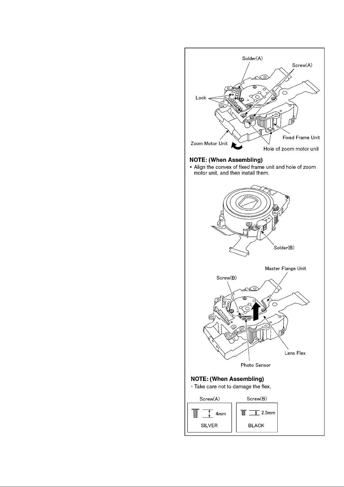
3.1.1. Removal of the Zoom Motor Unit
and Lens Flex P.C.B. Unit
1. Remove the 1 solder (A).
2. Remove the 3 locks.
3. Unscrew the 2 screws (A).
4. Remove the zoom motor unit to the indicated by arrow.
5. Remove the 1 solder (B).
6. Unscrew the 1 screw (B).
7. Remove the lens flex to the indicated by arrow.
7
 Loading...